Article

Self-Calibration Method for Circular Encoder Based on Two Reading Heads with Adjustable Positions

1
School of Mechatronics Engineering, Henan University of Science and Technology, Luoyang 471003, China
2
Henan Key Laboratory of Mechanical Design and Transmission System, Henan University of Science and Technology, Luoyang 471003, China
*
Author to whom correspondence should be addressed.
Machines 2024, 12(4), 246; https://doi.org/10.3390/machines12040246
Submission received: 15 March 2024 / Revised: 6 April 2024 / Accepted: 7 April 2024 / Published: 9 April 2024
(This article belongs to the Section Advanced Manufacturing)

Abstract

:
To improve the measuring accuracy of circular encoders in special applications, self-calibration of the circular encoder is necessary. The commonly used self-calibration method, namely the Equal Division Average (EDA) method, requires a large number of reading heads and cannot be used when the structural space is limited. In this paper, a self-calibration method for a circular encoder based on two reading heads with adjustable positions (TRAP) is proposed. This TRAP method uses two reading heads to simulate multiple reading heads, which can be used to achieve self-calibration of circular encoders in limited space. This paper investigates the principle of simulating multiple reading heads with two reading heads, designs and builds an experimental system, and obtains and analyzes experimental data. The experimental results show that the peak-valley value of the angle measurement error is reduced from 252.41″ to 18.82″ after self-calibration with the TRAP method, and the repeatability of multiple self-calibration experimental results is less than 0.75″. The TRAP method breaks through the limitation of the number of reading heads that can be installed during the self-calibration of the circular encoder and can effectively suppress the angle measurement error of the circular encoder.

1. Introduction

Precision angle measurement plays an important role in fields such as astronomical measurement, geographic surveying, aerospace, and precision machining. The circular encoder is a common high-precision angle sensor with the advantages of strong anti-interference ability and low cost. However, in practical applications, due to factors such as the grating engraving process, temperature, humidity, vibration, installation, and others, the circular encoder will exhibit an error in angle measurement. The main sources of angle measurement error in circular encoders include installation error, engraving error, and electronic subdivision error. Among these, the installation error caused by the eccentricity and inclination of the circular encoder accounts for the main part [1,2,3]. In order to improve the angle measurement accuracy of circular encoders, it is necessary to calibrate the encoders (i.e., measure and compensate for the angle measurement error of the circular encoder).
At present, many self-calibration methods for circular encoders have been proposed. Zhang [4] analyzed the optical dial-type circular indexing measurement device and found that when n reading heads are evenly distributed around the circumference of the dial and the average value of n reading heads is taken as the output value, all reading errors caused by harmonics other than integer orders of n can be eliminated. Probst [5] proposed a prime factor division (PFD) calibration method that calibrates divided circles using a prime factor algorithm based on a discrete Fourier transform to improve measuring accuracy. Lu et al. [6,7] introduced a new Time-measurement Dynamic Reversal (TDR) method to calibrate the circular encoder and compared it with the Equal Division Average (EDA) method to verify the effectiveness of the method. Feng et al. [8] used two reading heads to establish an eccentricity error model for the circular encoder, solving relevant eccentricity parameters based on the L–M algorithm and compensation for the eccentricity error in the measurement results of a single reading head. Jiao et al. [9,10] presented an optimization-based arrangement method for self-calibration of angle encoders. Based on the properties of Fourier analysis, the angle difference between reading heads was analyzed to determine the optimal arrangements of reading heads, and the optimal arrangements for two, three, and four reading heads were given. Wang et al. [11,12] used multiple reading heads to construct an equal-difference phase for error correction in order to ensure the accuracy of the angle measurement of the sensor. ISHII et al. [13,14] proposed a new self-calibration method with multiple reading heads that enables the detection of higher-order harmonic errors with a smaller number of reading heads and improves measurement accuracy. Zhang et al. [15,16,17] established a functional relationship between measurements and errors based on the principle of circular closure and the properties of the Fourier series and achieved self-calibration of the circular encoder with a single reading head. Zhang et al. [18] proposed a self-calibration method for circular encoders with multiple reading heads, deduced and analyzed the principle of error suppression of the reading head layout on the calibration results through harmonic analysis of angle measurement errors, and established a non-uniformly distributed layout of the reading heads to eliminate higher-order harmonic errors. Li et al. [19] introduced the main sources of error in angle measurements of circular encoders, analyzed the distribution pattern of angle measurement errors, and calibrated the accuracy of angle measurement using higher precision instruments. Additionally, the calibrated error data were fitted into a third-order sine function for error correction, and the effectiveness of the error correction was verified through experiments. Currently, the multiple reading head methods, including the Equal Division Average (EDA) method and the Unequal Division Average method, are commonly used self-calibration methods for circular encoders [20]. When the size of the circular encoder is fixed, the number of reading heads that can be installed is limited due to the constraints of the diameter of the circular encoder and the size of the reading head. In addition, the cost of the self-calibration system will increase if a larger number of reading heads are used.
In this paper, a self-calibration method for a circular encoder based on two reading heads with adjustable positions (TRAP) is proposed, which uses two reading heads to simulate multiple reading heads and achieve the calibration effect of multiple reading heads. The method breaks through the limitation of the number of reading heads that can be installed and can improve the measuring accuracy of the circular encoder.
This paper verifies the feasibility of the TRAP method and provides a new approach for high-precision self-calibration of circular encoders in a limited space, which has good research value. When space is not limited and the calibration effect of the TRAP method is compared with other (including the previously mentioned) calibration methods for circular encoders, the measurement accuracy that the TRAP method can achieve may be equivalent to or insufficient for them. In this case, this method may not be the best choice. However, when space is limited, the TRAP method has good applicability and can achieve a good self-calibration effect for a circular encoder. In this case, this method would be a good choice.

2. Self-Calibration Principle

The principle of the EDA method is based on the Fourier series and the circular closed principle, where m reading heads are evenly distributed around the circular encoder, and the m reading heads are used to eliminate harmonic errors other than k = c × m order (c = 1, 2, 3,…) [21,22,23].
The principle of self-calibration in this paper is to use two reading heads with adjustable positions to simulate the multi-reading head method, as exemplified by the simulating of the EDA method, which is described below.

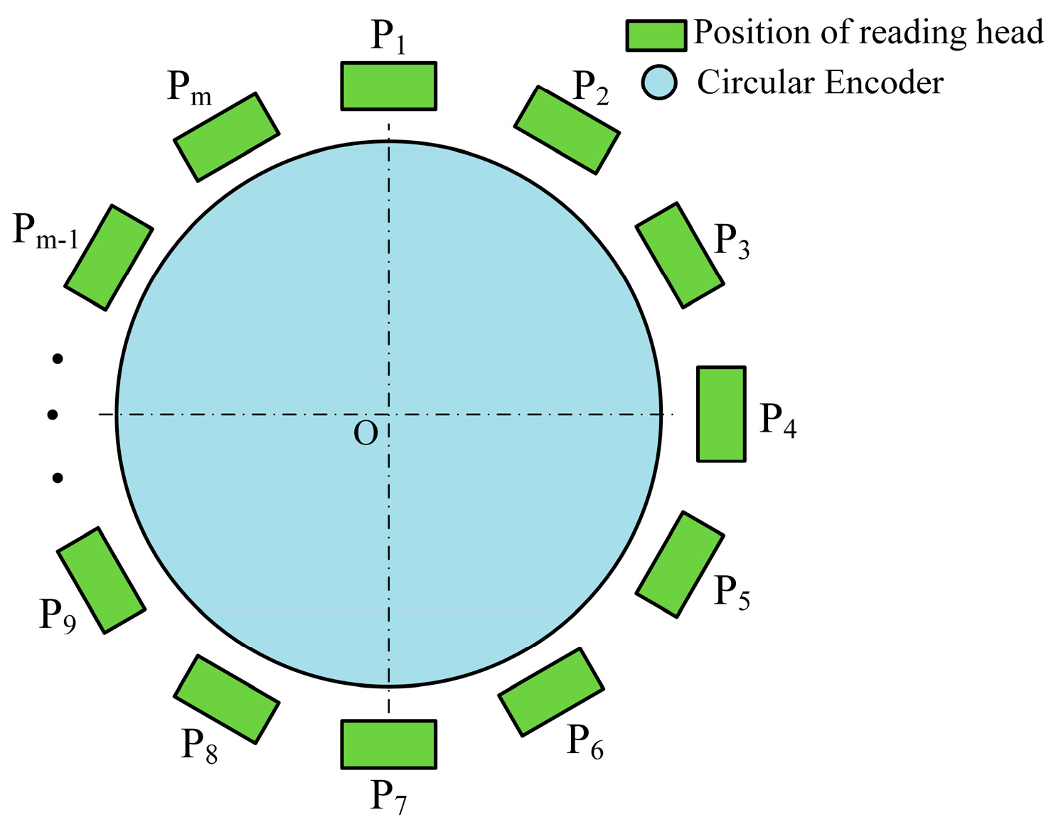
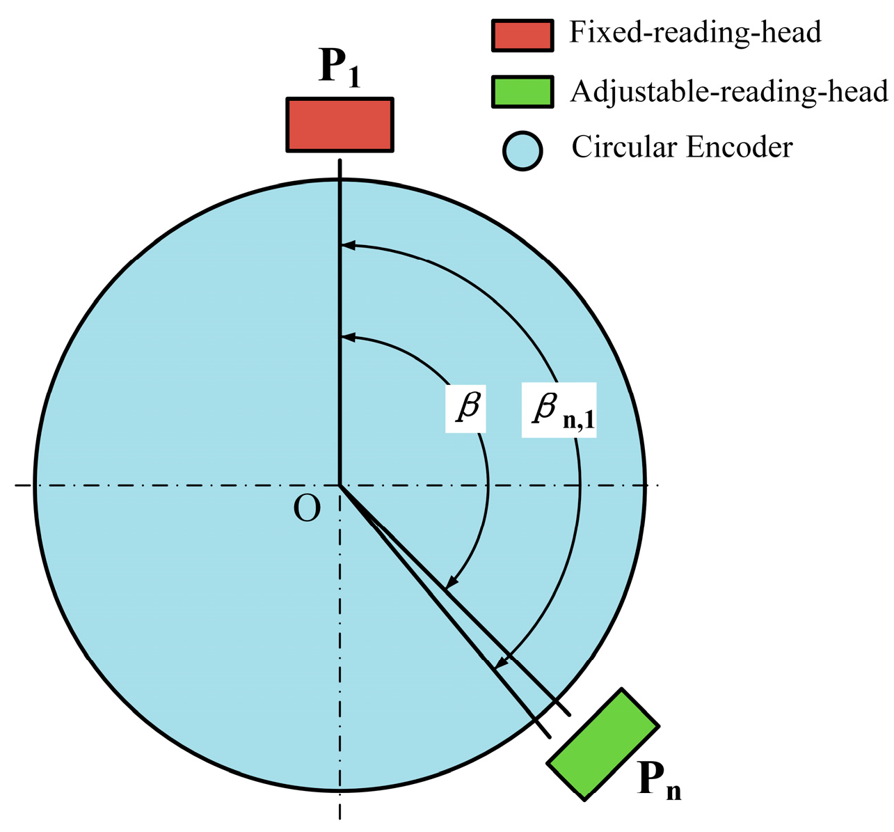
2.1. Calculation Method for Actual Angle between Reading Heads

The circular encoder for self-calibration is an incremental encoder. When the circular encoder is rotated by an angle θ, according to the definition of error, the measured value of a single reading head can be expressed as:
f i ( θ ) = θ + Δ ε i ( θ ) ,
where i = 1 , 2 , 3 m is the serial number of the location of the reading head, f i ( θ ) is the measured value of the i-th reading head, θ is the true value of the rotation angle of the circular encoder, and Δ ε i ( θ ) is the error value in angle measurement of the i-th reading head.
Two reading heads with adjustable positions are installed around the circular encoder, both of which can rotate around the circular encoder and are called fixed reading heads and adjustable reading heads, respectively. As shown in Figure 1, the fixed reading head is located at position P1, and the adjustable reading head is located at position Pn. The theoretical angle between the two reading heads is βn, 1, and the actual angle between the two reading heads is β.
When the rotation center of the circular encoder is at point-o in Figure 1, the true value of the rotation angle of the circular encoder satisfies:
θ n = θ 1 ,
where θ n is the true value of the adjustable reading head, θ 1 is the true value of the fixed reading head. However, due to factors such as the scribing error of the circular encoder and the subdivision error of the reading head, the actual readings of the two reading heads are not the same during the rotation of the circular encoder. According to Formulas (1) and (2), it can be known that the measurement difference between the two reading heads is:
Δ f n , 1 = f n ( θ ) f 1 ( θ ) = Δ ε n ( θ ) Δ ε 1 ( θ ) ,
In the subscript of Δ f n , 1 , n is the serial number of the location of the adjustable reading head, and 1 is the serial number of the location of the fixed reading head.
There is an error between the actual angle β and the theoretical angle βn, 1 between the two reading heads. In order to obtain a better self-calibration, it is necessary to obtain as accurate as possible β. The angle β between the actual installation positions of the two reading heads can be calculated from the readings of the two reading heads. For this purpose, the reading values of two reading heads are recorded at the time when the circular encoder zero-line passes through the two reading heads, respectively. When the circular encoder zero-line passes through the fixed reading head (position P1), the reading values of the fixed reading head are recorded as F1, and the reading values of the adjustable reading head are recorded as V1. When the circular encoder zero-line passes through the adjustable reading head (position Pn), the reading values of the fixed reading head are recorded as F2, and the reading values of the adjustable reading head are recorded as V2. Calculate the actual angle β between the installation positions of the two reading heads according to the following formula:
β = ( ( F 2 F 1 ) + ( V 2 V 1 ) ) / 2 ,
In theory, each time the adjustable reading head changes position, it should move to the designated position Pn so that the angle between the fixed reading head and the adjustable reading head is βn, 1. However, in practical application, there is a positioning error when the adjustable reading head is shifted to a specified position; there is an error between the actual angle β and the theoretical angle βn, 1 between the two reading heads, as shown in Figure 1. In the method of this paper, if |ββn, 1| < 0.03°, it can be considered that the adjustable reading head has moved to the specified position; that is, the positioning error of the reading head can be negligible. The reason is that the amplitude of the angular error is small, the influence on the self-calibration results of the TRAP method is very small, and it is already possible to obtain a sufficiently high self-calibration accuracy of the circular encoder.

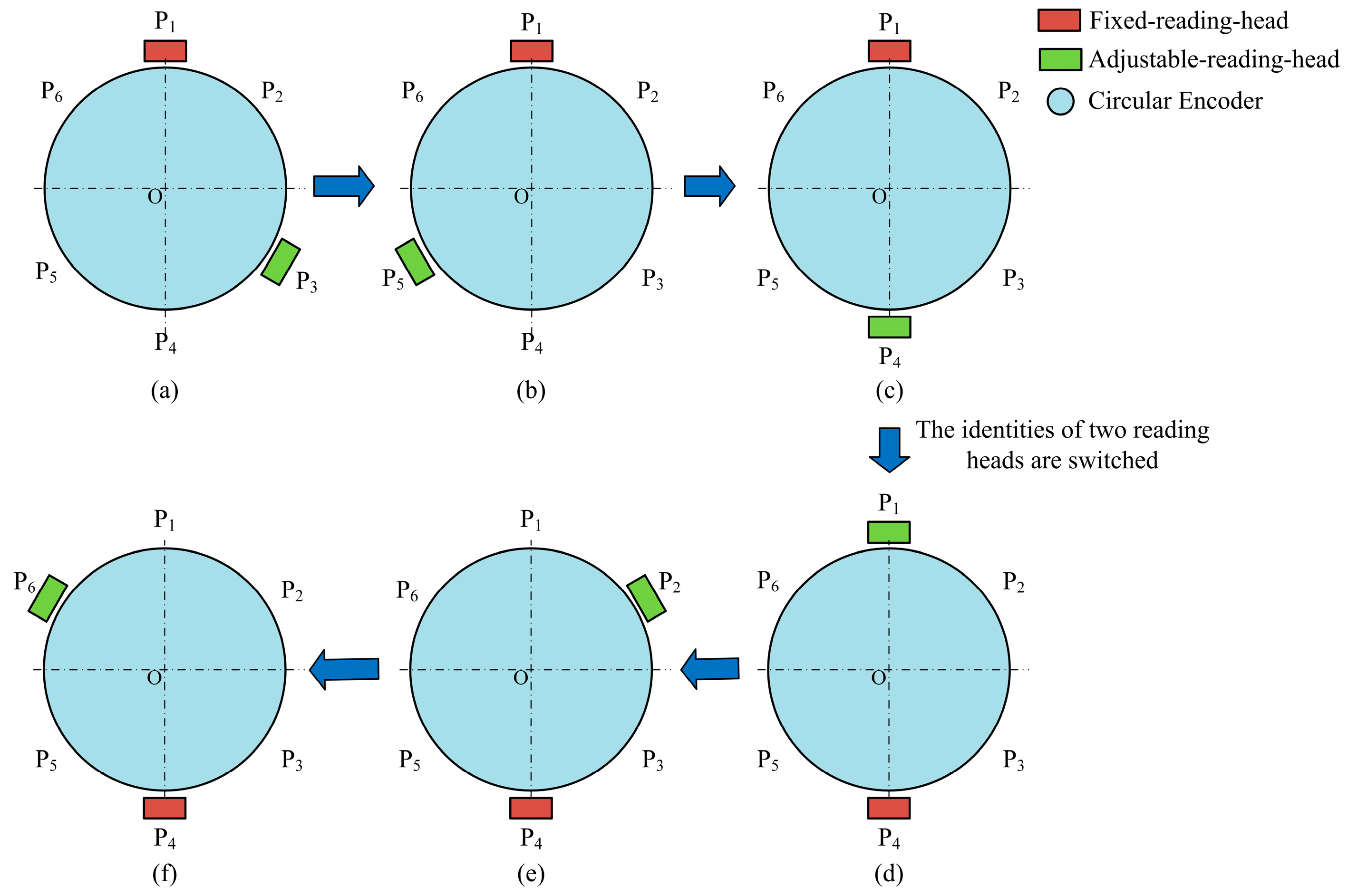
2.2. Self-Calibration Principle Based on Two Reading Heads with Adjustable Positions

As shown in Figure 2, the positions of the m reading heads are uniformly divided around the circular encoder, where m is the number of reading heads for the two reading heads simulation. The fixed reading head is located at position Pi, and the adjustable reading head is located at position Pj. At the current position, the theoretical angle βj,i between the two reading heads and the measurement difference Δfj,i between the two reading heads are calculated as follows:
β j , i = ( | j i | ) 360 m ,
Δ f j , i = f j ( θ ) f i ( θ ) ,
where i and j are the serial numbers of the position of the fixed reading head and the adjustable reading head, respectively, i = 1, 2, 3,…, m; j = 1, 2, 3,…, m.
Due to the size limitations of the circular encoder and reading head, there will be an allowable minimum angle between the two reading heads. In the EDA method, if the number of reading heads m is too large, the interference of two reading heads will occur when they are in adjacent positions. For example, assuming a minimum angle of 60°, if m = 12, the angle between adjacent reading-head mounting positions is 360°/12 = 30°. However, interference may occur due to 30° < 60°, which cannot be realized. In practice, the number of reading heads is limited by their size. In order to solve this problem, this paper proposes a method to perform permutation calculations that breaks through the limitation of the number of reading heads in this case.
This self-calibration method is based on whether there is interference between two reading heads and divides the calculation process into two parts, as detailed below. As shown in Figure 2, the fixed reading head is at position P1. Assuming that, due to size constraints, there is interference between the two reading heads when the adjustable reading head is located at position P2 or position Pm, and there is non-interference between the two reading heads when the adjustable reading head is at position Pj (j = 3, 4, …, m − 1).
When there is no interference between the two reading heads, the fixed reading head is located in position P1, and the adjustable reading head is changed several times. When the adjustable reading head is separately located at position Pj (j = 3, 4, …, m − 1), the measurements between the two reading heads can be collected. According to Formula (6), it can be inferred that the measurement difference between the two reading heads is:
Δ f j , 1 = f j ( θ ) f 1 ( θ ) ,
where j = 3, 4, …, m − 1.
When there is interference between the two reading heads, the fixed reading head is not moved, and the adjustable reading head is first shifted to a position that does not interfere with position P2 and position Pm. For example, if the adjustable reading head is located at position P4, it is known that the measurement difference between the two reading heads is at position P1 and position P4, respectively.
Δ f 4 , 1 = f 4 ( θ ) f 1 ( θ ) ,
Then, the identities of the two reading heads are reversed, and the original adjustable reading head is changed to the fixed reading head, and the original fixed reading head is changed to the adjustable reading head; that is, the fixed reading head is located at position P4 and the adjustable reading head is located at position P1. Keep the fixed reading head at position P4, change the adjustable reading head several times, and when the adjustable reading head is at position P2 and position Pm, respectively, the data between the two reading heads can be collected. According to Formula (6), it can be inferred that the measurement difference between the two reading heads is:
Δ f j , 4 = f j ( θ ) f 4 ( θ ) ,
where j = 2, m. Derived from Formulas (8) and (9)
Δ f j , 1 = Δ f j , 4 + Δ f 4 , 1 = f j ( θ ) f 1 ( θ ) ,
where j = 2, m. From the above, the measurement difference Δfj, i (j = 1, 2, …, m) between the two reading heads is obtained, and then it is averaged by summing the
Δ f = j = 1 m Δ f j , 1 m ,
In this way, an error in the angle measurement of the circular encoder can be calculated, which is used for error compensation. The method realizes the simulation of the EDA method by using two reading heads for the self-calibration of the circular encoder.
This method can also use two reading heads with adjustable positions to simulate the optimization method of multiple reading heads [24,25], the Unequal Division Average method. The process is similar to the above, and the efficiency of self-calibration can be improved.

3. Design and Construction of Experimental System

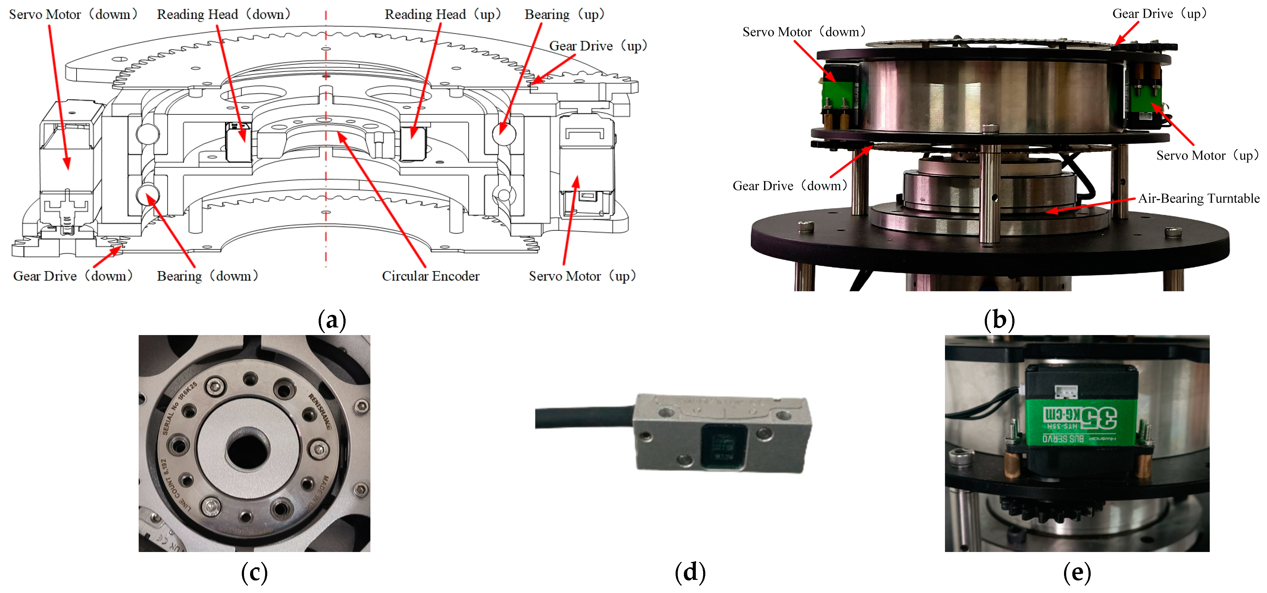
3.1. Structural Design of Self-Calibration Device

The mechanical structure of the self-calibration device in the experimental system is shown in Figure 3. In the figure, the circular encoder is RESM20 of Renishaw’s VIONiC (52 mm diameter, ±3.97″ scribing accuracy, 20 μm pitch, 8192 lines); the reading head is V2CL of Renishaw’s VIONiC (20 nm resolution, clocked at 50 MHz); and the servo motor is HTS-35H of Hiwonder (0.2° servo accuracy). The self-calibration device uses the axis of the circular encoder as the axis of rotation, and two reading heads with adjustable positions are installed around the circular encoder. Through the gear drive section, the two reading heads are, respectively, controlled by the corresponding servo motor. By controlling the servo motor, the rotation of the reading head around the circular encoder can be realized, which meets the design requirement that the two reading heads of the circular encoder can change their positions independently.

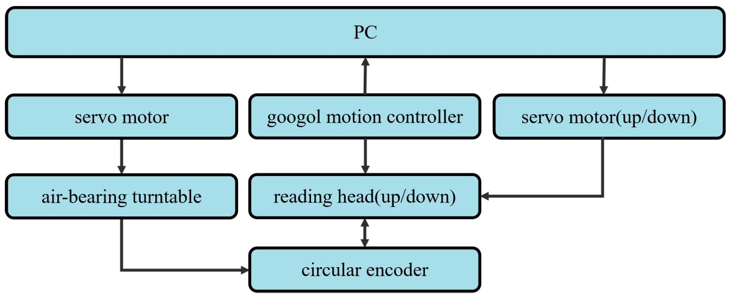
3.2. Design of Hardware Circuit and Software System

The hardware components of the experimental system include a circular encoder, reading heads, googol motion controller, and servo motors, as shown in Figure 4. The software running on a PC mainly realizes two functions: the data acquisition and processing function and the position control function of the reading head.
The principle of data acquisition and processing function is that the two reading heads are fixed, the PC sends control instructions to the servo motor, and the servo motor takes the air-bearing spindle and the circular encoder to rotate. Data information is collected by two reading heads at the same time as the rotation of the circular encoder, and then the collected data information is transmitted to the PC through the googol motion controller. Finally, the PC performs data processing on the collected data information and completes the data acquisition and processing function.
The principle of the position control function of the reading head is that the circular encoder is fixed, the PC sends control instructions to the servo motors (up/down), and the servo motors (up/down) control the rotation of the reading heads (up/down) corresponding to it. At the same time, the two reading heads collect the data produced in the rotation process of the reading heads and then transfer the collected data to the PC through the Googol motion controller to realize closed-loop feedback control to ensure the position of the reading head in the process of displacement to achieve the expected position and complete the position control function of the reading head.

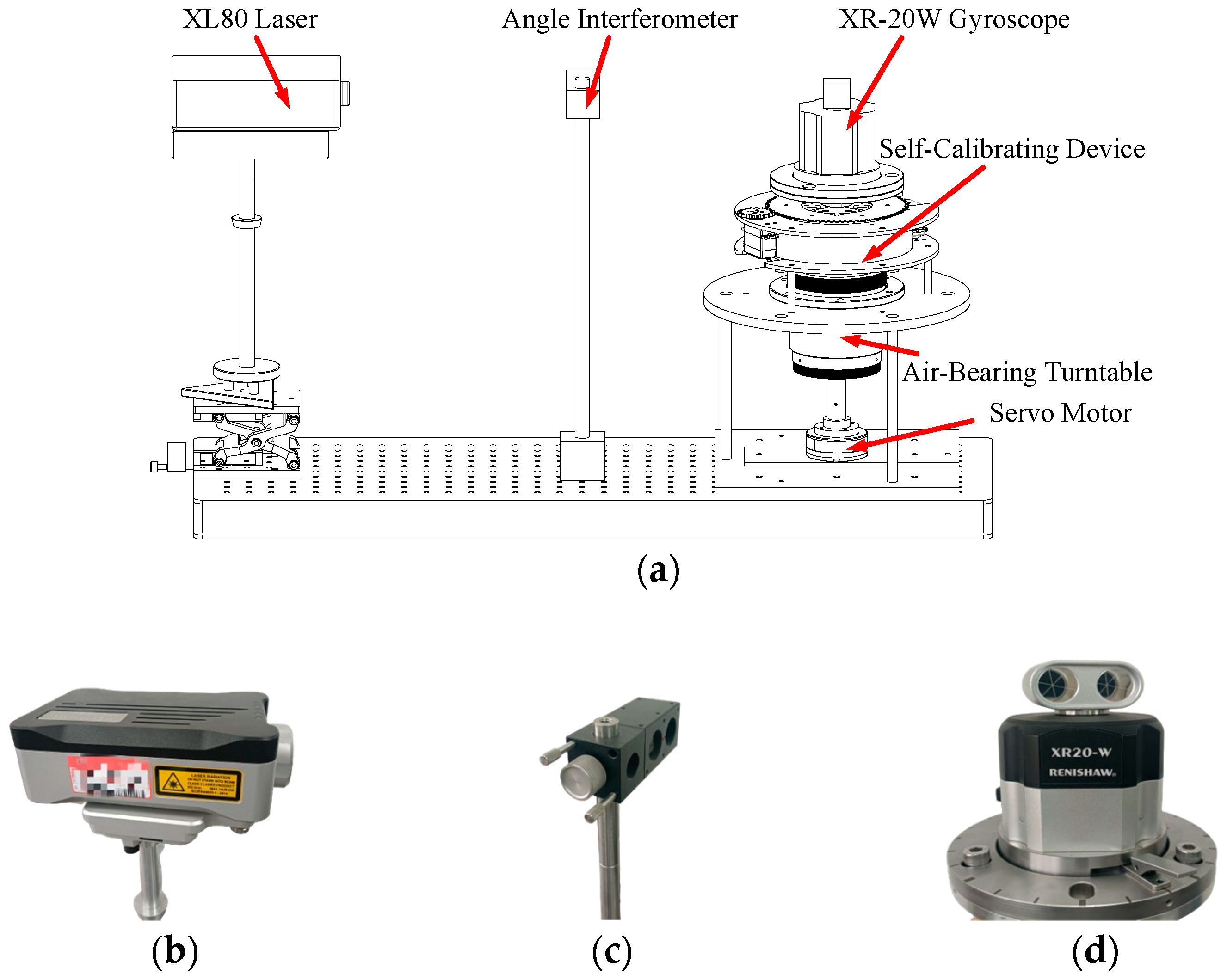
3.3. Construction of Experimental Platform

The experimental platform is shown in Figure 5. The internal structure of the self-calibrating device is shown in Figure 3. The circular encoder is fixed on the spindle of the air-bearing turntable. The installation position of the circular encoder needs to be corrected, and the axial and radial runout of the circular encoder after correction is less than 0.05 mm. The installation position of the reading head also needs to be adjusted so that the indicator of the reading head shows normal operation, and the indicator shows normal operation when the reading head rotates around the circular encoder. Two servo motors control the rotation of the two reading heads through gear drive, respectively, and a servo motor is located at the bottom of the air-bearing turntable and drives the air-bearing spindle to rotate. In order to explain the effect of the method in this paper, an angular measuring system of a laser interferometer is also installed in the experiment platform. The laser interferometer includes an XL80 laser module (±0.5 ppm system accuracy (0~40 °C), 0.001 μm resolution), an angle interferometer, and an XR-20W gyroscope (±1″ measuring accuracy). In the experiment, experimental data obtained by Renishaw’s laser interferometer are taken as references, and the validity of the method is verified by comparing the angle measurement error of the circular encoder before and after self-calibration.

4. Experiment

4.1. Experimental Process

In this experiment, the self-calibration method of two reading heads simulating six reading heads is used as an example to explain the process of the self-calibration method in this paper. The process of adjusting the position of the reading heads is shown in Figure 6. At first, the fixed reading head is at position P1, and the adjustable reading head is at positions P3, P5, and P4, respectively. Then, the identities of the fixed reading head and the adjustable reading head are switched; the fixed reading head is at position P4, and the adjustable reading head is at positions P1, P2, and P6, respectively.
The measurements of the reading head at each position are shown in Table 1, where m is the number of measurements of the reading head during one rotation of the circular encoder. In order to ensure the integrity of data information and improve accuracy, record two or more cycles of data information each time, take out two or more whole circles of data from the data information, and take the average value of the data of each circle. The data information to be recorded should include the measurement data as the zero line of the circular encoder passes through each reading head. After recording, mark the current installation position of the two reading heads as having been measured in the list of installed positions of the reading heads.
In Table 1, the data measured by the fixed reading head and the adjustable reading head are presented in an array; measurements in Table 1 are data of two whole circles. In the subscript of Pi, j, i represents the number of measurements, and j represents the installation position; in the subscript of Pi, j, K, i represents the number of measurements, j represents the installation position, and k represents the serial number of data.
Each set of measurements is recorded from the time when the zero line of the circular encoder passes through each reading head. The aim is to align all the data, that is, make the data in each curve have a uniform starting point or put the curves in the same coordinate system.
As mentioned earlier, to reduce the impact of random errors, the collected data can be averaged. The idea of the averaging process is to take the average value of the corresponding m data for each cycle. The specific data processing method is described in the self-calibration principle section. The compensation data for error in angle measurement of the circular encoder, which can be obtained by data processing, can be used to improve the measuring accuracy of the circular encoder.

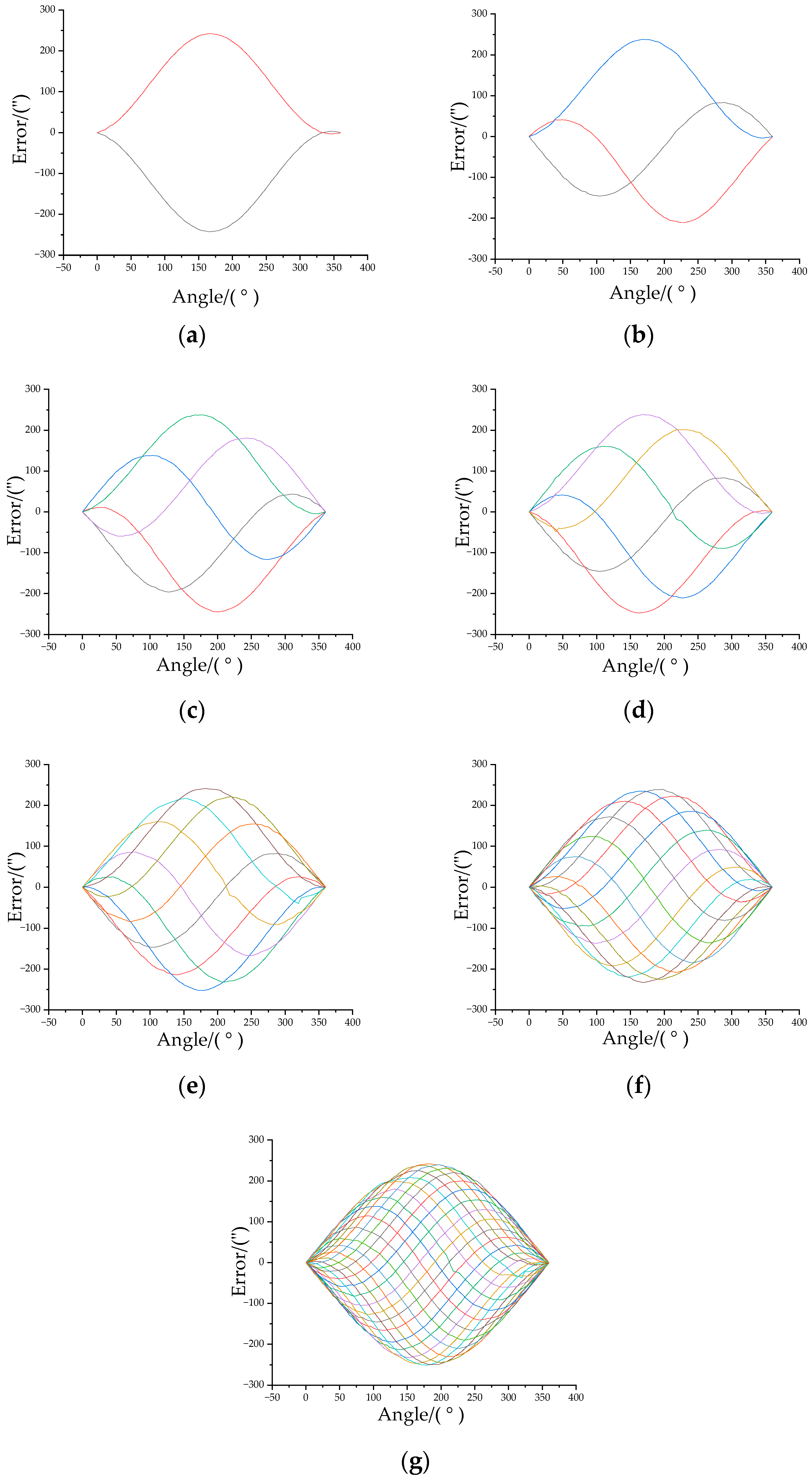
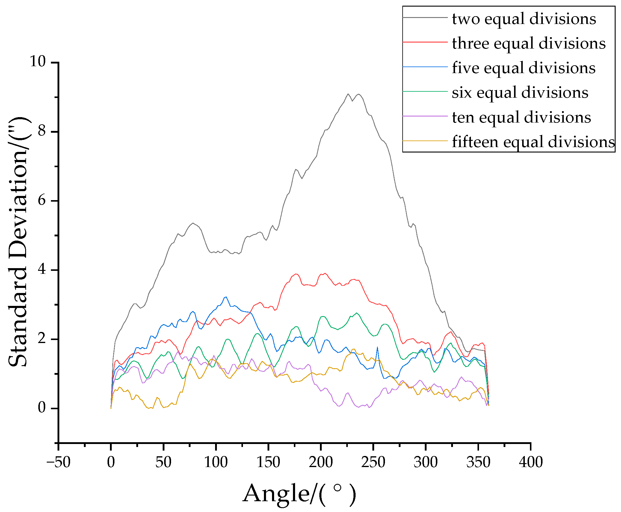
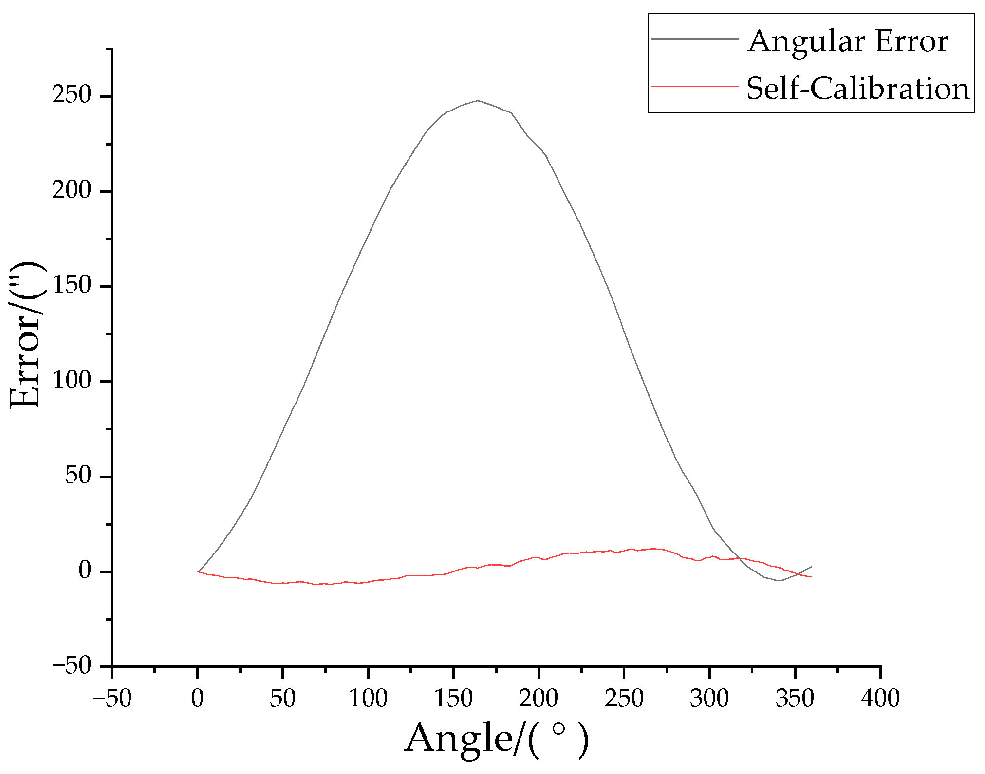
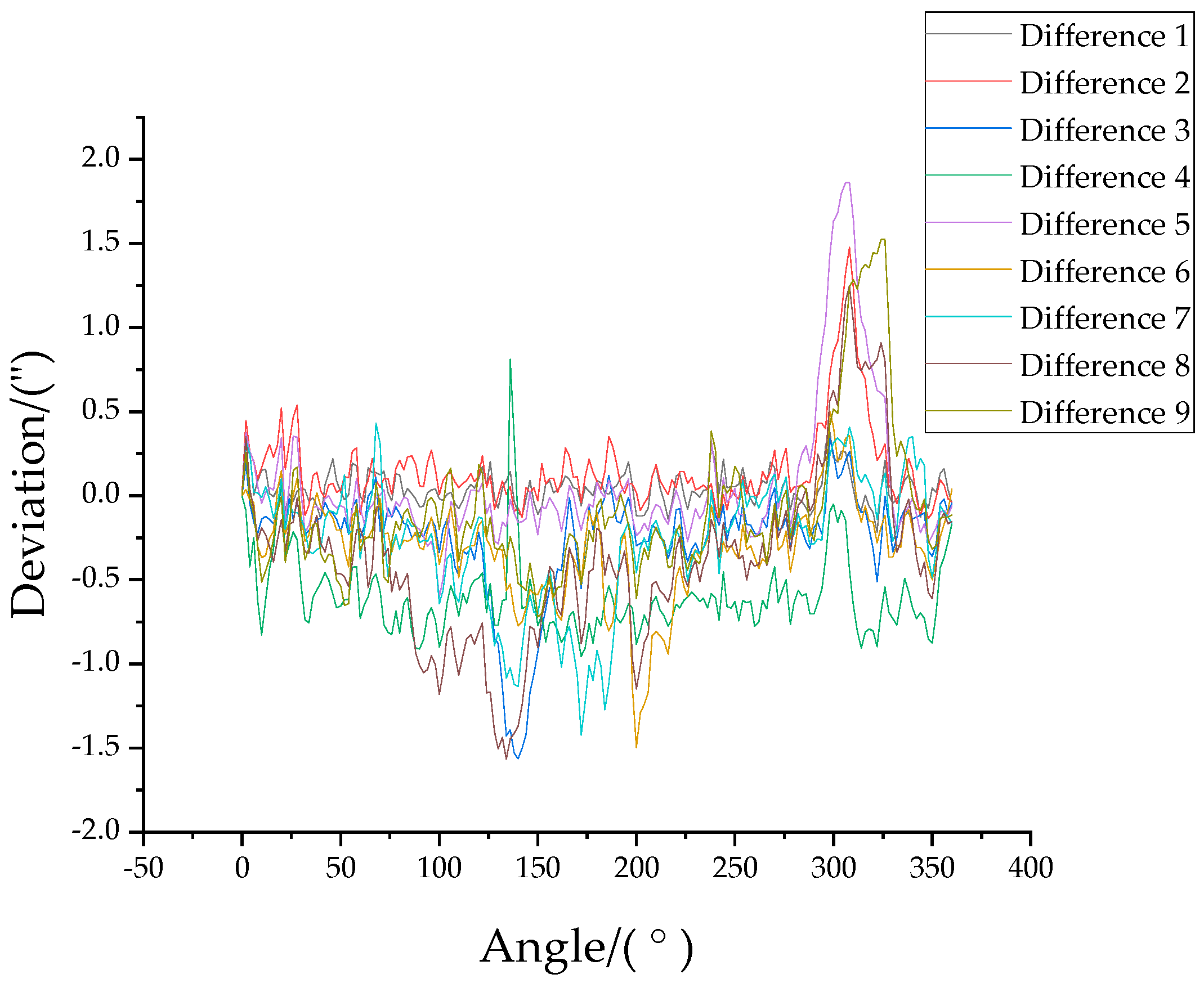
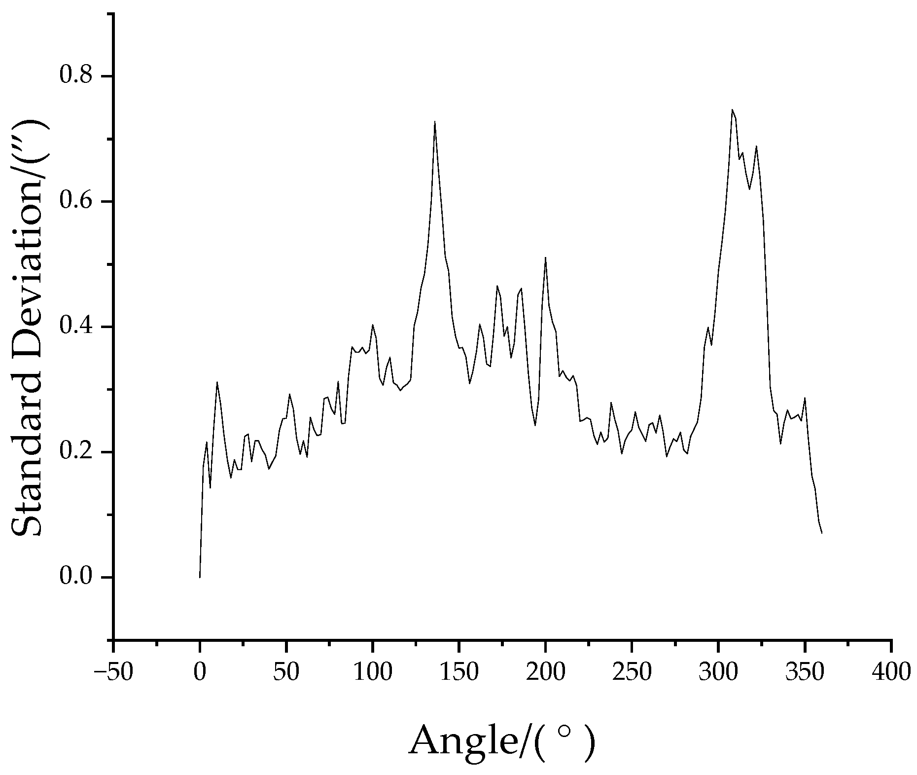
4.2. Analysis of Experimental Data

Through the experimental process as described in Section 4.1, the two reading heads can be used to simulate different numbers of reading heads and obtain an error curve with the zero line of the circular encoder as the starting point for the corresponding case. Figure 7 shows the error curve of each position when two reading heads simulate two, three, five, six, ten, fifteen, and thirty reading heads. As shown in Figure 7, in the same set of equal data, the error curves of reading heads at different positions follow a certain regularity; that is, the error curve at any one position can be converted into an error curve at other positions by adjusting the phase and initial zero-position of the error curve.
In practical applications, there are many interference factors, such as environmental vibration, noise, the installation position of reading heads, the shaking of the turntable, etc. These factors will randomly affect the measurements of the reading head to different degrees. Therefore, using two reading heads to simulate more reading heads can make the overall calibration process more stable and improve the effect of calibration.
In the experiment with the self-calibration method, the measured data of 30 reading heads are simulated by two reading heads. The data can be subdivided again into 15 groups of two equal divisions, 10 groups of three equal divisions, 6 groups of five equal divisions, 5 groups of six equal divisions, 3 groups of ten equal divisions, and 2 groups of fifteen equal divisions.
The difference in data for each group can be used as an indicator to evaluate the stability of the self-calibration results of the TRAP method in this paper. The variability of each group of data can be quantified by calculating the standard deviation of the data in this group. Figure 8 shows the standard deviation for each group with different equal divisions. The legend in Figure 8 represents the number of equal divisions. As can be seen in Figure 8, the variability of the measured data is gradually reducing as the number of reading heads simulated by the two reading heads increases. The difference between the groups of data is greatest in the two equal divisions. In this case, the standard deviation is calculated as follows:
σ ( y i ) = i = 1 n ( y i y ¯ ) 2 n 1 ,
where i = 2, 3, …, n is the serial number of the data, y i is the data of group-i, y ¯ is the average of group-n of measurements, and n is the number of groups under the equal division if there are 15 groups of two equal divisions; that is, n = 15.
In order to verify the repeatability of the experimental system, 10 sets of two reading heads simulating three reading heads (three equal divisions) were carried out under the premise of ensuring the same installation position of the virtual reading head. Figure 9 shows the difference between the data from the group-1 trial and the data from the other nine groups. As can be seen in Figure 9, the repeatability of the data for each group of measurements is good. Further, the standard deviation of these data in Figure 9 is also calculated, and the results are shown in Figure 10, where Max ( σ ( y i ) ) = 0.75″ for all measured positions.

4.3. Comparison with Interferometric Measurements

In order to verify the validity of the self-calibration method, the circular encoder was measured using an interferometer; the measured value was taken as the true value of the rotation angle of the circular encoder. Then, it was compared and analyzed with the data measured using the simulated thirty equal divisions using the TRAP method.
As shown in Figure 11, it is a comparison graph of the measurement errors before and after the error compensation under the current experimental conditions. Before error compensation, the error peaks are 247.72″ and −4.69″, respectively, and the error of angle measurement is 252.41″; after error compensation, the error peaks are reduced to 12.10″ and −6.72″, respectively, and the error of angle measurement is 18.82″. Through THE contrast experiment, it can be clearly seen that the use of the present self-calibration method has an obvious suppression effect on the error of angle measurement.

5. Conclusions

In this paper, a self-calibration method for a circular encoder based on two reading heads with adjustable positions is presented. This method collects measurement data of the reading head at different positions through multiple positional changes of two reading heads with adjustable positions, establishes the correlation between these measurement data, and then calculates the angle measurement error of the circular encoder, achieving self-calibration of the circular encoder. At the same time, this paper also designed the mechanical structure, hardware circuit, and software system of the self-calibration system and completed the construction of the experimental platform. Through analysis and comparison of the experimental data, it can be seen that the method has a significant reduction effect on an error of angle measurement. Under the present experimental conditions, the error in angle measurement of the circular encoder is reduced from 252.41″ to 18.82″, and the repeatability error of the self-calibration result is less than 0.75″.
The self-calibration method proposed in this paper provides a new approach to the study of the high-precision self-calibration of circular encoders in a limited space. However, this paper only studied the EDA method. In future research, it may be necessary to simulate the method of non-uniform layout of multiple reading heads to improve the efficiency of self-calibration of circular encoders. Due to the limitations of experimental conditions, the experimental data in this paper were inevitably affected by environmental interference. In the future, the effect of self-calibration on this method will be further explored by optimizing the experimental conditions.

Author Contributions

Conceptualization, X.W. and C.Z.; methodology, X.W. and C.Z.; software, X.W. and C.Z.; validation, X.W. and C.Z.; formal analysis, X.W., C.Z. and L.X.; investigation, X.W., C.Z. and K.Z.; resources, X.W., C.Z., L.X., K.Z., M.L., D.Z. and T.Y.; data curation, X.W. and C.Z.; writing—original draft preparation, X.W. and C.Z.; writing—review and editing, X.W. and C.Z.; visualization, X.W. and C.Z.; supervision, X.W. and C.Z.; project administration, X.W. All authors have read and agreed to the published version of the manuscript.

Funding

This research was funded by the National Natural Science Foundation of China (52227809, 51775172).

Data Availability Statement

The data that support the findings of this study are available from the corresponding author upon reasonable request.

Conflicts of Interest

The authors declare no conflicts of interest.

References

  1. Jia, H.K.; Yu, L.D.; Zhao, H.N.; Jiang, Y.Z. A New Method of Angle Measurement Error Analysis of Rotary Encoders. Appl. Sci. 2019, 9, 3415. [Google Scholar] [CrossRef]
  2. Li, Y.T.; Fan, K.C. A novel method of angular positioning error analysis of rotary stages based on the Abbe principle. Proc. Inst. Mech. Eng. Part B J. Eng. Manuf. 2018, 232, 1885–1892. [Google Scholar] [CrossRef]
  3. Li, G.L.; Xue, Z.; Huang, Y.; Zhu, W.B.; Zou, W. Indication error analysis and compensation of circular grating angle measurement system. Chin. J. Sci. Instrum. 2021, 42, 59–65. [Google Scholar] [CrossRef]
  4. Zhang, S.Z. The principle of eliminating errors in the multi reading head structure of high-precision circular indexing measurement devices. Tool Eng. 1982, 6, 42–46. [Google Scholar] [CrossRef]
  5. Probst, R. Self-calibration of divided circles on the basis of a prime factor algorithm. Meas. Sci. Technol. 2008, 19, 015101. [Google Scholar] [CrossRef]
  6. Lu, X.D.; Trumper, D.L. Self-Calibration of On-Axis Rotary Encoders. CIRP Ann.-Manuf. Technol. 2007, 56, 499–504. [Google Scholar] [CrossRef]
  7. Lu, X.D.; Graetz, R.; Amin-Shahidi, D.; Smeds, K. On-axis self-calibration of angle encoders. CIRP Ann.-Manuf. Technol. 2010, 59, 529–534. [Google Scholar] [CrossRef]
  8. Feng, C.P.; Zhu, L.Q.; Pan, Z.K.; Guo, Y.K. New self-calibration method of circular grating eccentric parameters. Chin. J. Sci. Instrum. 2016, 37, 2459–2464. [Google Scholar] [CrossRef]
  9. Jiao, Y.; Dong, Z.G.; Ding, Y.; Liu, P.K. Optimal arrangements of scanning heads for self-calibration of angle encoders. Meas. Sci. Technol. 2017, 28, 105013. [Google Scholar] [CrossRef]
  10. Jiao, Y.; Dong, Z.G.; Huang, M.; Liu, P.K. Optimal-arrangement-based four-scanning-heads error separation technique for self-calibration of angle encoders. Meas. Sci. Technol. 2018, 29, 085005. [Google Scholar] [CrossRef]
  11. Wang, X.Q.; Yu, Y.; Zhu, G.L.; Jiang, Z.H.; Zhao, T.T. Multiple Reading Head Displacement Sensor Research Based on Arithmetic Phase. Instrum. Tech. Sens. 2016, 9, 1–4+63. [Google Scholar] [CrossRef]
  12. Wang, X.Q.; Zhao, T.T.; Wen, C.Y.; Wang, L.; Wang, P.Y. Error Correcting for Displacement Sensor Based on Multiple Reading Head. Tool Eng. 2017, 51, 121–126. [Google Scholar] [CrossRef]
  13. Ishii, N.; Taniguchi, K.; Yamazaki, K.; Aoyama, H. Development of super-accurate angular encoder system with multi-detecting heads using VEDA method. J. Adv. Mech. Des. Syst. Manuf. 2018, 12, JAMDSM0106. [Google Scholar] [CrossRef]
  14. Ishii, N.; Taniguchi, K.; Yamazaki, K.; Aoyama, H. Super-Accurate Angular Encoder System with Multi-Detecting Heads Using VEDA Method. J. Jpn. Soc. Precis. Eng. 2018, 84, 717–723. [Google Scholar] [CrossRef]
  15. Zhang, W.Y.; Lao, D.B.; Zhou, W.H.; Zhu, H.R. Development and experiment of online self-calibration system for circular grating angle sensor. Infrared Laser Eng. 2018, 47, 224–229. [Google Scholar] [CrossRef]
  16. Zhang, W.Y.; Lao, D.B.; Zhou, W.H.; Zhu, H.R. Self-Calibration Method Based on Multi-head Reading Layout. Acta Opt. Sin. 2018, 38, 352–358. [Google Scholar] [CrossRef]
  17. Zhang, W.Y.; Zhu, H.R.; Li, M.X.; Guo, Z.X.; Guo, M. Real-Time In-Situ Calibration for Angle Measuring Sensors Based on Autocollimator. Chin. J. Lasers 2019, 46, 166–172. [Google Scholar] [CrossRef]
  18. Zhang, R.; Bao, W.; Zhao, H.; Jia, H.; Yu, L. Self-calibration method of precision shafting angle measurement error based on multiple reading heads. In Proceedings of the Tenth International Symposium on Precision Engineering Measurements and Instrumentation, Kunming, China, 8–10 August 2018. [Google Scholar] [CrossRef]
  19. Li, Z.M.; Li, Z.L.; Han, B.; Tang, Y.F.; Yang, Y.Q.; Ma, Y. Compensation Method of Circular Grating Angle Measurement Error. Instrum. Tech. Sens. 2021, 10, 56–59+89. [Google Scholar] [CrossRef]
  20. Masuda, T.; Kajitani, M. An automatic calibration system for angular encoders. Precis. Eng. 1989, 11, 95–100. [Google Scholar] [CrossRef]
  21. Just, A.; Krause, M.; Probst, R.; Bosse, H.; Haunerdinger, H.; Spaeth, C.; Metz, G.; Israel, W. Comparison of angle standards with the aid of a high-resolution angle encoder. Precis. Eng. 2009, 33, 530–533. [Google Scholar] [CrossRef]
  22. Sun, S.Z.; Zhang, Z.M.; Han, Y.; Tao, P.A.; He, Z.Y. Self-calibration study of the embedded angular displacement sensor based on single probe error phase shift method. Chin. J. Sci. Instrum. 2022, 43, 96–103. [Google Scholar] [CrossRef]
  23. Li, G.L.; Xue, Z.; Huang, Y.; Zhu, W.B.; Zou, W. System error separation and compensation of the continuous full circle angle standard device. Chin. J. Sci. Instrum. 2021, 42, 1–9. [Google Scholar] [CrossRef]
  24. Geckeler, R.D.; Link, A.; Krause, M.; Elster, C. Capabilities and limitations of the self-calibration of angle encoders. Meas. Sci. Technol. 2014, 25, 055003. [Google Scholar] [CrossRef]
  25. Probst, R.; Wittekopf, R.; Krause, M.; Dangschat, H.; Ernst, A. The new PTB angle comparator. Meas. Sci. Technol. 1998, 9, 1059–1066. [Google Scholar] [CrossRef]
Figure 1. Position of two reading heads (fixed reading head is at P1; adjustable reading head is at Pn).
Machines 12 00246 g001
Figure 2. Positions of the reading heads when simulating the EDA method.
Machines 12 00246 g002
Figure 3. Structural of the self-calibration device. (a) Schematic diagram of the self-calibration device; (b) Physical diagram of the self-calibration device; (c) RESM20 circular encoder of Renishaw’s VIONiC; (d) V2CL reading head of Renishaw’s VIONiC; (e) HTS-35H servo motor of Hiwonder.
Machines 12 00246 g003
Figure 4. Block diagram of hardware circuit system.
Machines 12 00246 g004
Figure 5. Experimental platform. (a) Schematic diagram of the experimental platform; (b) XL80 laser module; (c) angle interferometer; (d) XR-20W gyroscope.
Machines 12 00246 g005
Figure 6. Process of adjusting positions of two reading heads. (a) Fixed reading head is at P1 and adjustable reading head is at P3; (b) Fixed reading head is at P1 and adjustable reading head is at P5; (c) Fixed reading head is at P1 and adjustable reading head is at P4; (d) The identities of two reading heads are switched; fixed reading head is at P4, and adjustable reading head is at P1; (e) Fixed reading head is at P4, and adjustable reading head is at P2; (f) Fixed reading head is at P4, and adjustable reading head is at P6.
Machines 12 00246 g006
Figure 7. Measured error curve of each position when two reading heads simulate multiple reading heads (different equal divisions). (a) Two equal divisions; (b) three equal divisions; (c) five equal divisions; (d) six equal divisions; (e) ten equal divisions; (f) fifteen equal divisions; (g) thirty equal divisions.
Machines 12 00246 g007
Figure 8. Standard deviation of differences in multiple sets of data (with different numbers of read heads).
Machines 12 00246 g008
Figure 9. Difference curve of three equal divisions.
Machines 12 00246 g009
Figure 10. Standard deviation of three equal divisions.
Machines 12 00246 g010
Figure 11. Comparison of curves before and after error compensation.
Machines 12 00246 g011
Table 1. Measurements of the reading heads at each location.
Number of MeasurementsPosition of Fixed Reading HeadPosition of Adjustable Reading HeadMeasurements of Two Reading HeadsPosition Marked as Measured
1P1P3 P 1 , 1 = { p 1 , 1 , 1 , p 1 , 1 , 2 , , p 1 , 1 , 2 m } P 1 , 3 = { p 1 , 3 , 1 , p 1 , 3 , 2 , , p 1 , 3 , 2 m } P1, P3
2P1P5 P 2 , 1 = { p 2 , 1 , 1 , p 2 , 1 , 2 , , p 2 , 1 , 2 m } P 2 , 5 = { p 2 , 5 , 1 , p 2 , 5 , 2 , , p 2 , 5 , 2 m } P1, P3, P5
3P1P4 P 3 , 1 = { p 3 , 1 , 1 , p 3 , 1 , 2 , , p 3 , 1 , 2 m } P 3 , 4 = { p 3 , 4 , 1 , p 3 , 4 , 2 , , p 3 , 4 , 2 m } P1, P3, P4, P5
4P4P2 P 4 , 4 = { p 4 , 4 , 1 , p 4 , 4 , 2 , , p 4 , 4 , 2 m } P 4 , 2 = { p 4 , 2 , 1 , p 4 , 2 , 2 , , p 4 , 2 , 2 m } P1, P2, P3, P4, P5
5P4P6 P 5 , 4 = { p 5 , 4 , 1 , p 5 , 4 , 2 , , p 5 , 4 , 2 m } P 5 , 6 = { p 5 , 6 , 1 , p 5 , 6 , 2 , , p 5 , 6 , 2 m } P1, P2, P3, P4, P5, P6
Disclaimer/Publisher’s Note: The statements, opinions and data contained in all publications are solely those of the individual author(s) and contributor(s) and not of MDPI and/or the editor(s). MDPI and/or the editor(s) disclaim responsibility for any injury to people or property resulting from any ideas, methods, instructions or products referred to in the content.

