
AI-Driven Virtual Sensors for Real-Time Dynamic Analysis of Mechanisms: A Feasibility Study


Abstract
1. Introduction
1.1. Novel Work and Motivation
1.2. Contribution
- This paper introduces a non-invasive virtual sensor as an alternative to traditional sensing systems, using cameras and leveraging data-driven inferential models to measure the forces involved in a mechanism.
- The exploitation of the proposed vision-based virtual sensor is an efficient solution in reducing the need for external sensors like force transducers or encoders, whose installation is often time-consuming and expensive.
- The virtual sensor has been developed also considering datasets with uncertainties, thus assessing the robustness of the overall measurement system to real-world disturbances.
- This study demonstrates the adaptability of the proposed solution in capturing and analyzing the dynamics of mechanical systems for real-time solutions.
1.3. Organization of the Paper
2. Materials and Methods
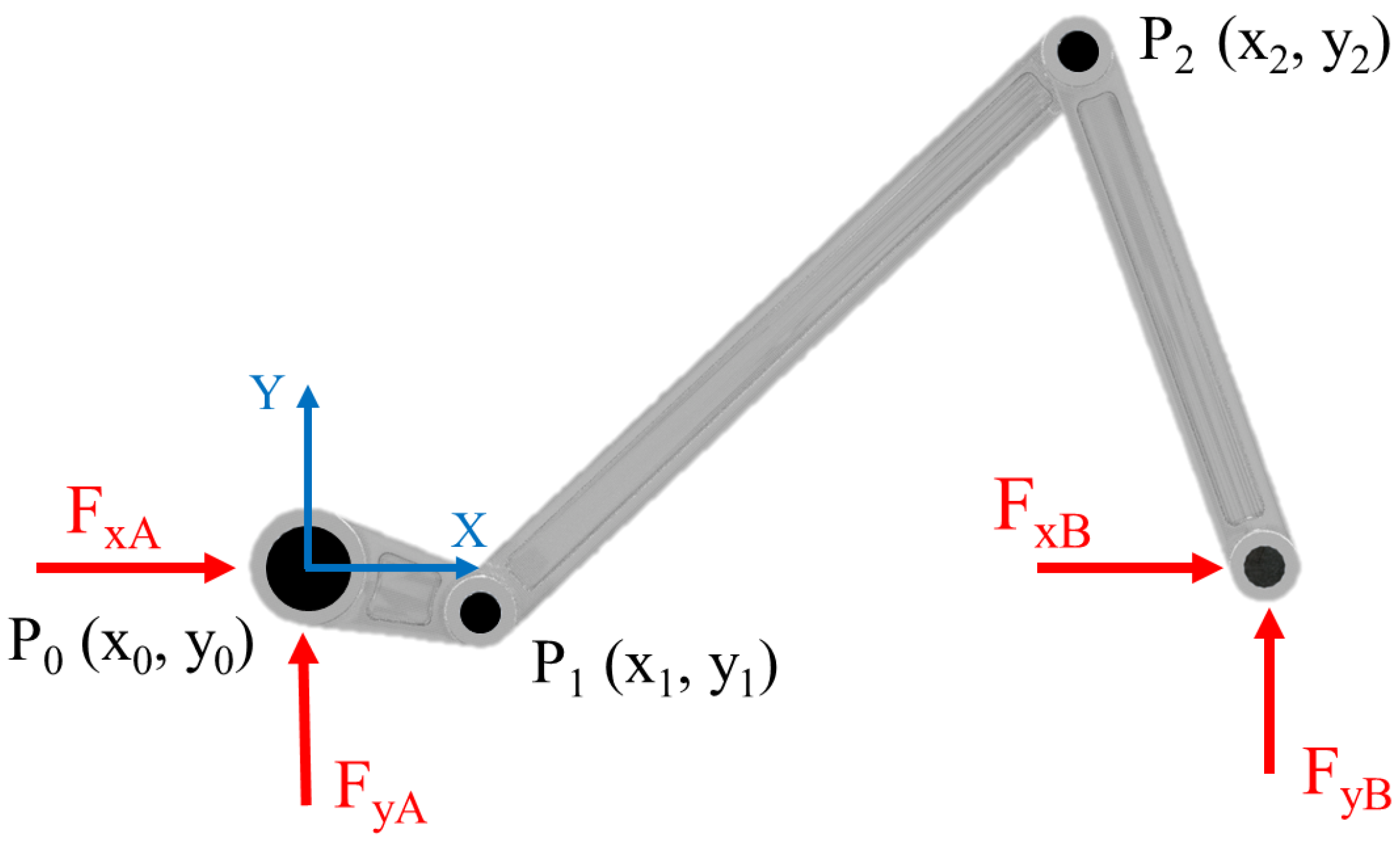
2.1. Multi-Body Model
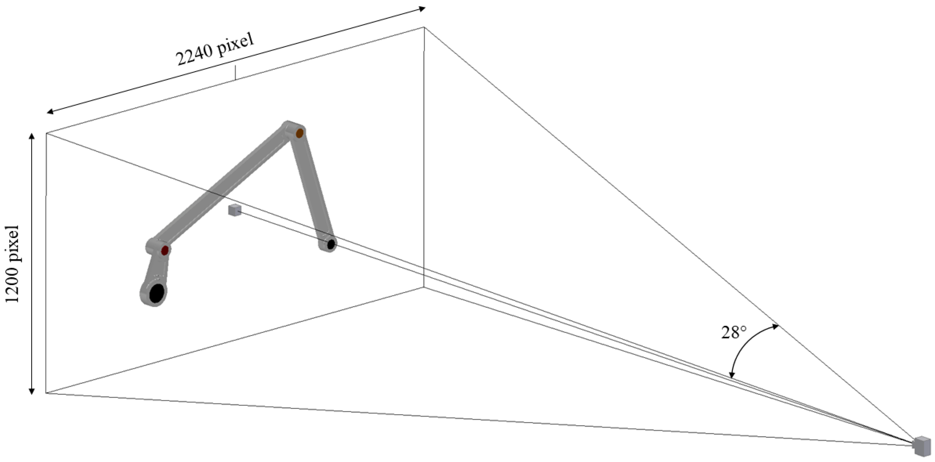
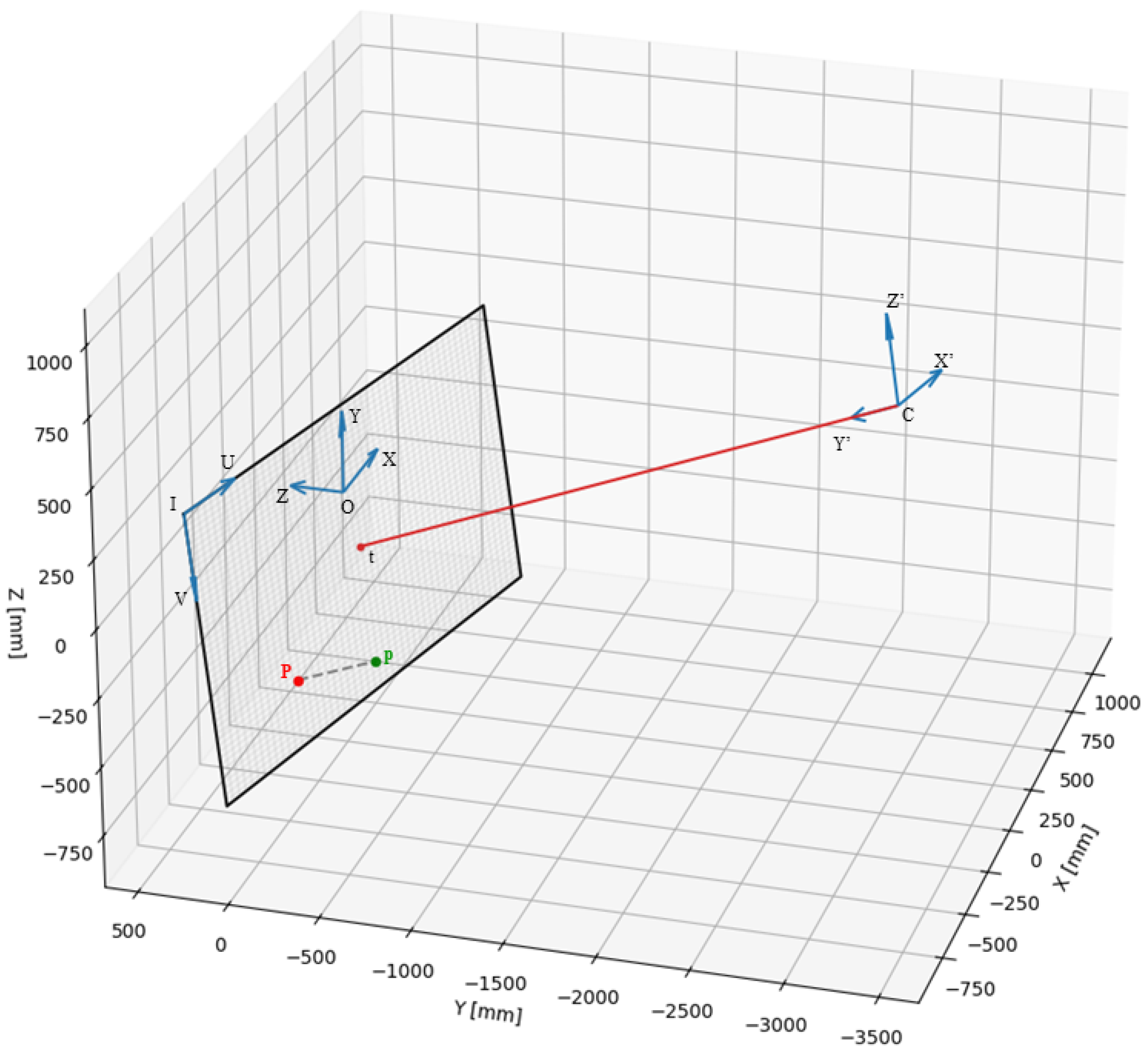
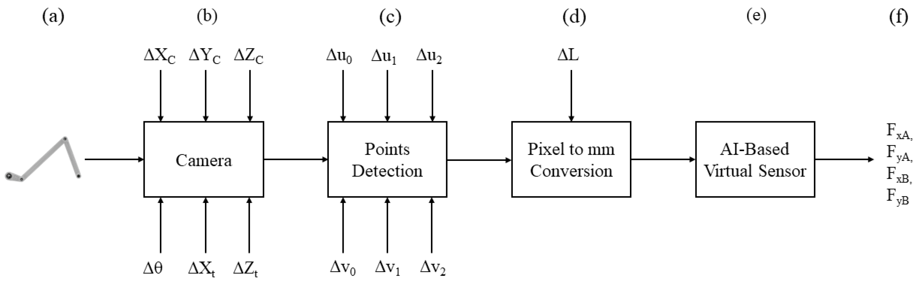
2.2. Camera Model
2.3. Data Collection
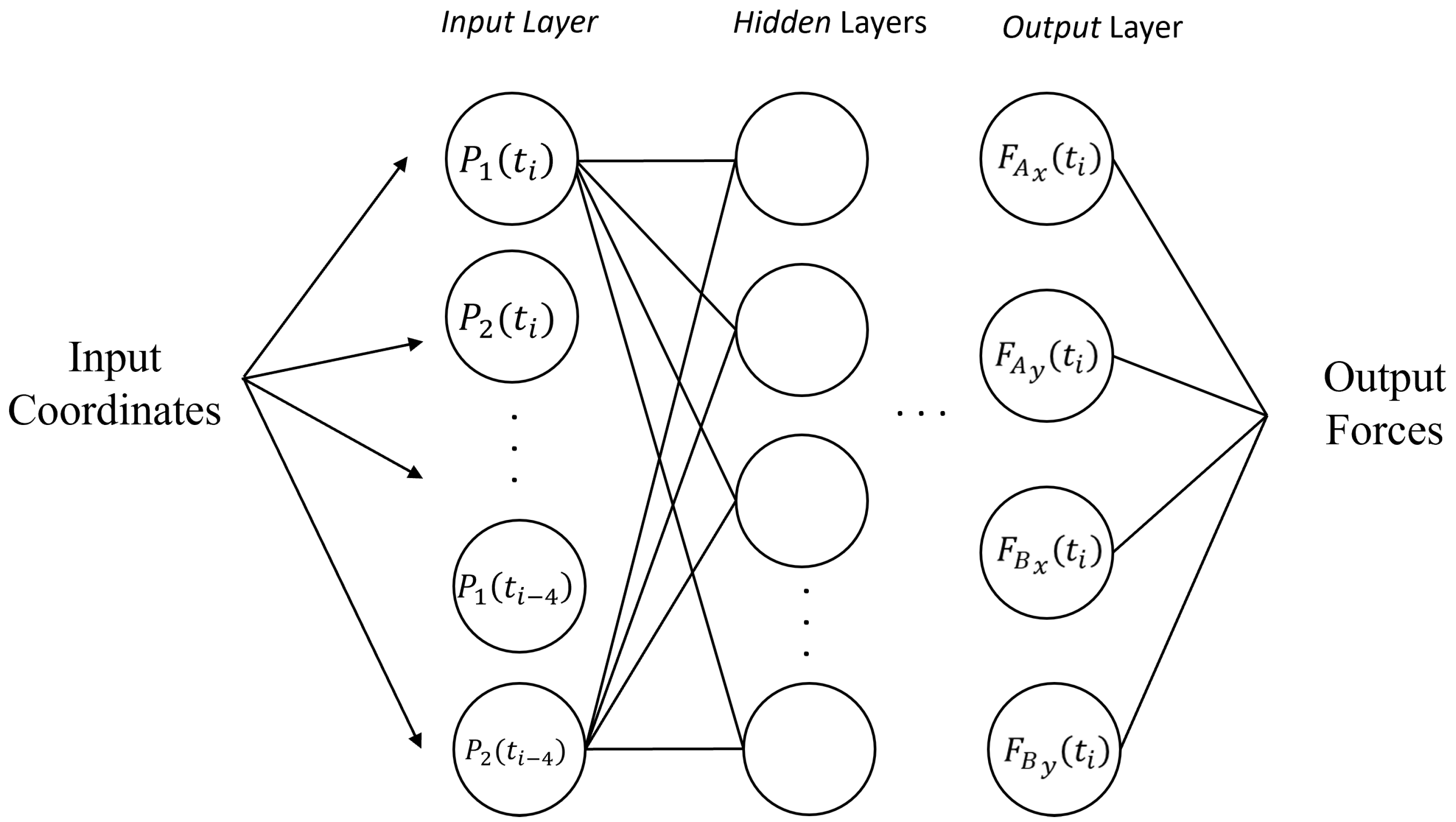
2.4. AI-Based Virtual Sensor for Ground Reaction Force Estimation
- Batch size : specifies the number of training samples processed in one iteration.
- Learning rate : determines the rate at which the model weights are updated during training.
- Optimizer o: updates the model based on the loss function. Options include SGD, Adam, RMSprop, Adadelta, and Adagrad [26].
- Number of layers : specifies the total number of layers in the network.
- Number of neurons per layer : specifies the number of neurons in each layer.
3. Results
3.1. Model Training
- Dataset 1:
- −
- Uses ideal data from the simulation. This dataset is designed to represent the best-case scenario without any external interference or noise, serving as a benchmark for optimal model performance.
- Dataset 2:
- −
- Accounts for possible interfering inputs (e.g., noise) within the measurement chain, simulating a real use case. The incorporation of such disturbances aims to mimic the challenges encountered in real case scenarios.
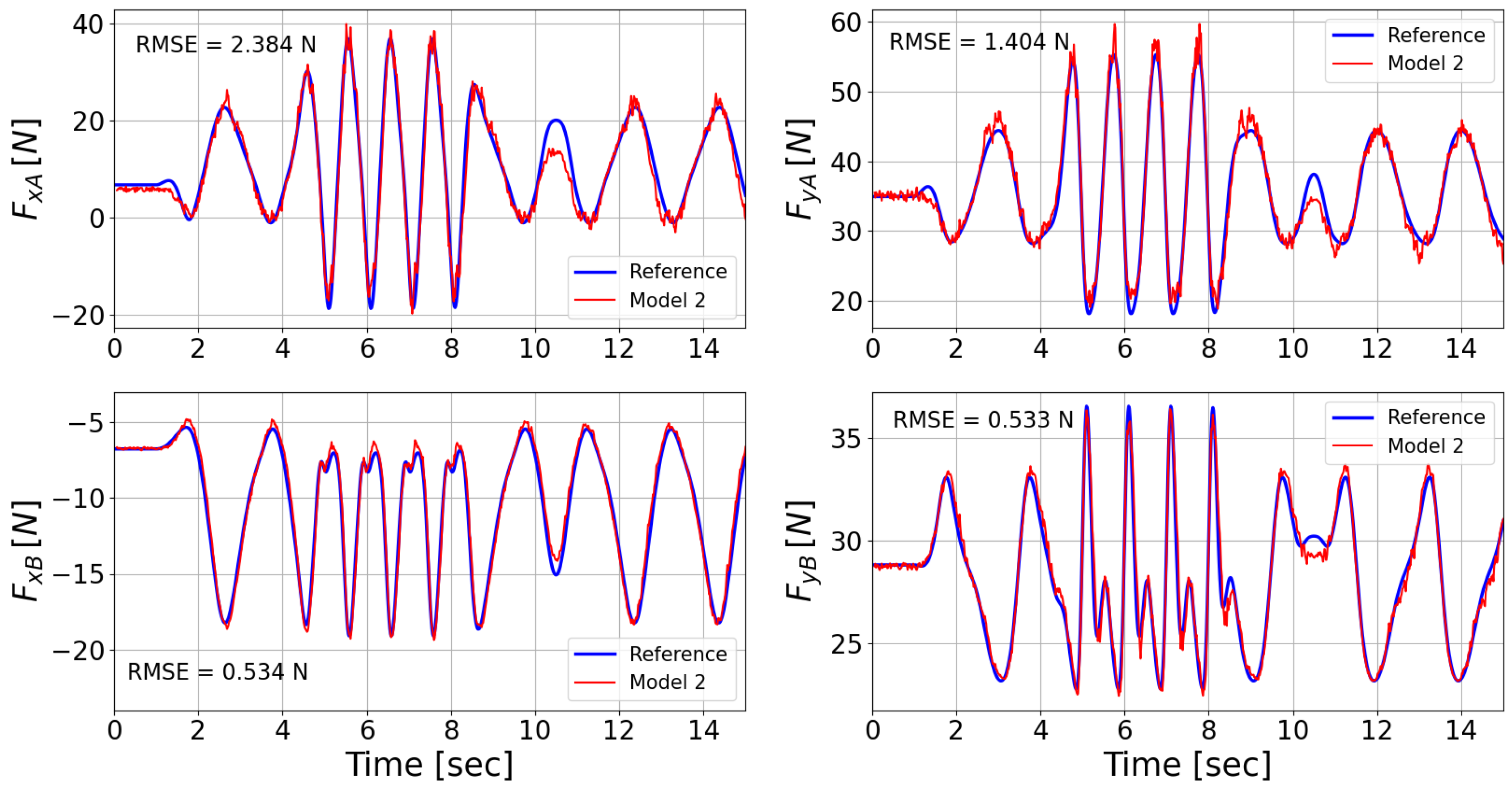
3.2. Model Testing
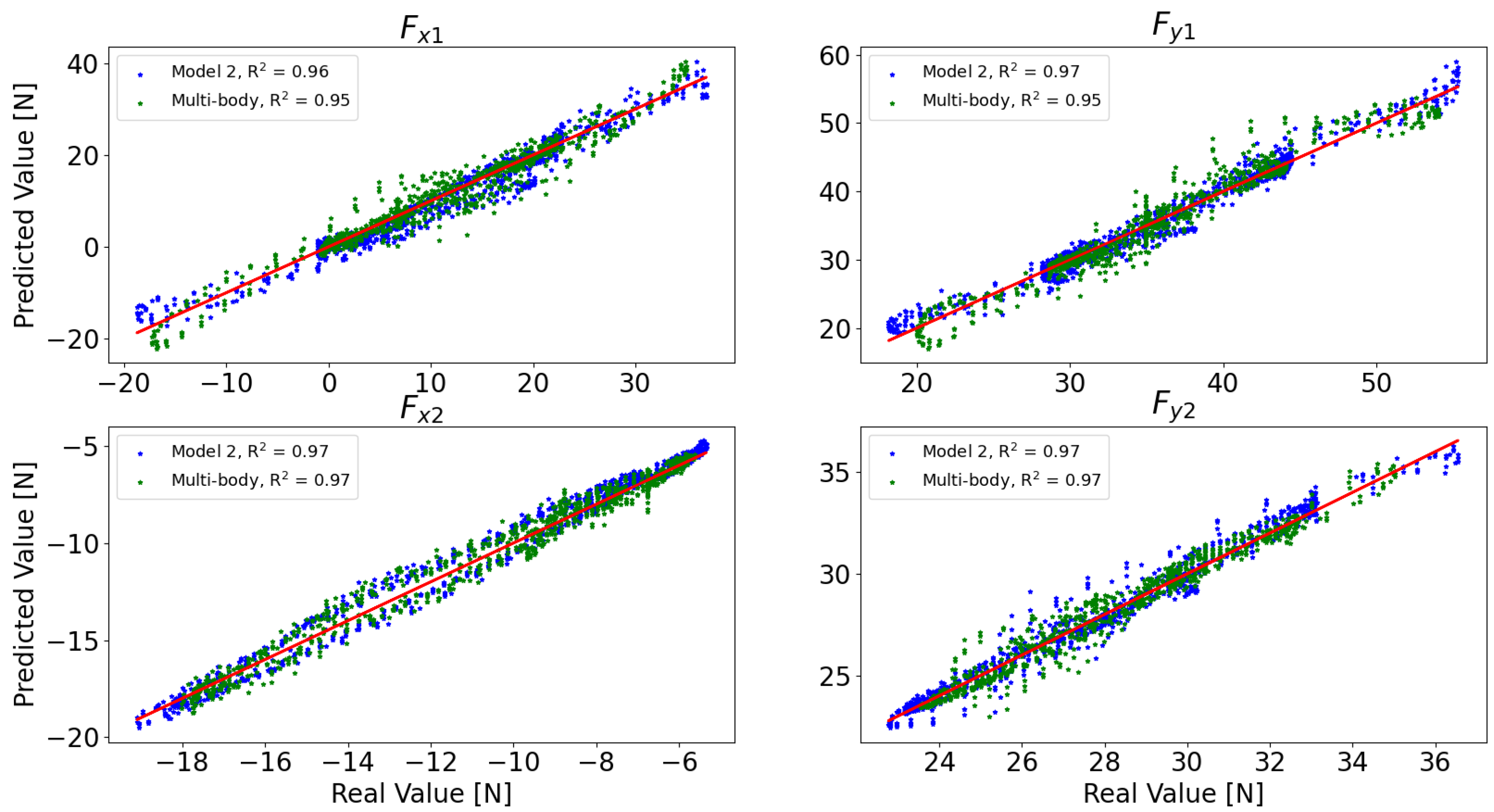
3.3. Multi-Body vs. Inferential Model
4. Conclusions
Author Contributions
Funding
Data Availability Statement
Conflicts of Interest
References
- Souza, F.A.; Araújo, R.; Mendes, J. Review of soft sensor methods for regression applications. Chemom. Intell. Lab. Syst. 2016, 152, 69–79. [Google Scholar] [CrossRef]
- Calvanese, L.; Carnevale, M.; Facchinetti, A. Fiber optic system to extend the measuring frequency range of pantograph contact force. In Proceedings of the 2022 Joint Rail Conference, JRC 2022, Virtual, 20–21 April 2022. [Google Scholar] [CrossRef]
- Carnevale, M.; Collina, A.; Palmiotto, M. Condition monitoring of railway overhead lines: Correlation between geometrical parameters and performance parameters. In Proceedings of the 1st World Congress on Condition Monitoring 2017, WCCM 2017, London, UK, 13–16 June 2017. [Google Scholar]
- Peinado-Asensi, I.; Montés, N.; García, E. Virtual Sensor of Gravity Centres for Real-Time Condition Monitoring of an Industrial Stamping Press in the Automotive Industry. Sensors 2023, 23, 6569. [Google Scholar] [CrossRef] [PubMed]
- Tang, Z.; Zhang, Z. The multi-objective optimization of combustion system operations based on deep data-driven models. Energy 2019, 182, 37–47. [Google Scholar] [CrossRef]
- Hu, X.; Cao, L.; Luo, Y.; Chen, A.; Zhang, E.; Zhang, W.J. A Novel Methodology for Comprehensive Modeling of the Kinetic Behavior of Steerable Catheters. IEEE/ASME Trans. Mechatron. 2019, 24, 1785–1797. [Google Scholar] [CrossRef]
- Etxegarai, M.; Camps, M.; Echeverria, L.; Ribalta, M.; Bonada, F.; Domingo, X. Virtual Sensors for Smart Data Generation and Processing in AI-Driven Industrial Applications. In Industry 4.0—Perspectives and Applications; IntechOpen: London, UK, 2022. [Google Scholar]
- Sun, Q.; Ge, Z. A Survey on Deep Learning for Data-Driven Soft Sensors. IEEE Trans. Ind. Inform. 2021, 17, 5853–5866. [Google Scholar] [CrossRef]
- Sabanovic, E.; Kojis, P.; Ivanov, V.; Dhaens, M.; Skrickij, V. Development and Evaluation of Artificial Neural Networks for Real-World Data-Driven Virtual Sensors in Vehicle Suspension. IEEE Access 2024, 12, 13183–13195. [Google Scholar] [CrossRef]
- Giulietti, N.; Allevi, G.; Castellini, P.; Garinei, A.; Martarelli, M. Rivers’ Water Level Assessment Using UAV Photogrammetry and RANSAC Method and the Analysis of Sensitivity to Uncertainty Sources. Sensors 2022, 22, 5319. [Google Scholar] [CrossRef] [PubMed]
- Byun, E.; Lee, J. Vision-based virtual vibration sensor using error calibration convolutional neural network with signal augmentation. Mech. Syst. Signal Process. 2023, 200, 110607. [Google Scholar] [CrossRef]
- Wang, Y.; Zhang, L.; Li, T.; Jiang, Y. A Model-based Analysis-Design Approach for Virtual Binocular Vision System with Application to Vision-based Tactile Sensors. IEEE Trans. Instrum. Meas. 2023, 72, 5010916. [Google Scholar] [CrossRef]
- Ögren, Y.; Tóth, P.; Garami, A.; Sepman, A.; Wiinikka, H. Development of a vision-based soft sensor for estimating equivalence ratio and major species concentration in entrained flow biomass gasification reactors. Appl. Energy 2018, 226, 450–460. [Google Scholar] [CrossRef]
- Alarcon, C.; Shene, C. Fermentation 4.0, a case study on computer vision, soft sensor, connectivity, and control applied to the fermentation of a thraustochytrid. Comput. Ind. 2021, 128, 103431. [Google Scholar] [CrossRef]
- Li, Y.; Ni, P.; Sun, L.; Xia, Y. Finite element model-informed deep learning for equivalent force estimation and full-field response calculation. Mech. Syst. Signal Process. 2024, 206, 110892. [Google Scholar] [CrossRef]
- Marban, A.; Srinivasan, V.; Samek, W.; Fernández, J.; Casals, A. A recurrent convolutional neural network approach for sensorless force estimation in robotic surgery. Biomed. Signal Process. Control 2019, 50, 134–150. [Google Scholar] [CrossRef]
- Ko, D.K.; Lee, K.W.; Lee, D.H.; Lim, S.C. Vision-based interaction force estimation for robot grip motion without tactile/force sensor. Expert Syst. Appl. 2023, 211, 118441. [Google Scholar] [CrossRef]
- Chen, K.; Zhao, W.; Zhang, X. Real-time milling force monitoring based on a parallel deep learning model with dual-channel vibration fusion. Int. J. Adv. Manuf. Technol. 2023, 126, 2545–2565. [Google Scholar] [CrossRef]
- Bakhshandeh, P.; Mohammadi, Y.; Altintas, Y.; Bleicher, F. Digital twin assisted intelligent machining process monitoring and control. CIRP J. Manuf. Sci. Technol. 2024, 49, 180–190. [Google Scholar] [CrossRef]
- Ksiazek, K.; Romaszewski, M.; Głomb, P.; Grabowski, B.; Cholewa, M. Blood Stain Classification with Hyperspectral Imaging and Deep Neural Networks. Sensors 2020, 20, 6666. [Google Scholar] [CrossRef]
- Giulietti, N.; Caputo, A.; Chiariotti, P.; Castellini, P. SwimmerNET: Underwater 2D Swimmer Pose Estimation Exploiting Fully Convolutional Neural Networks. Sensors 2023, 23, 2364. [Google Scholar] [CrossRef]
- Giulietti, N.; Discepolo, S.; Castellini, P.; Martarelli, M. Neural Network based Hyperspectral imaging for substrate independent bloodstain age estimation. Forensic Sci. Int. 2023, 39, 111742. [Google Scholar] [CrossRef]
- Giulietti, N.; Discepolo, S.; Castellini, P.; Martarelli, M. Correction of Substrate Spectral Distortion in Hyper-Spectral Imaging by Neural Network for Blood Stain Characterization. Sensors 2022, 22, 7311. [Google Scholar] [CrossRef]
- Nogueira, F. Bayesian Optimization: Open Source Constrained Global Optimization Tool for Python. 2014. Available online: https://github.com/fmfn/BayesianOptimization (accessed on 11 April 2024).
- Agrawal, T. Bayesian Optimization. In Hyperparameter Optimization in Machine Learning; Apress: Berkeley, CA, USA, 2020; pp. 81–108. [Google Scholar] [CrossRef]
- Abdulkadirov, R.; Lyakhov, P.; Nagornov, N. Survey of Optimization Algorithms in Modern Neural Networks. Mathematics 2023, 11, 2466. [Google Scholar] [CrossRef]
- Bai, Y.; Yang, E.; Han, B.; Yang, Y.; Li, J.; Mao, Y.; Niu, G.; Liu, T. Understanding and improving early stopping for learning with noisy labels. Adv. Neural Inf. Process. Syst. 2021, 34, 24392–24403. [Google Scholar]
- Raschka, S. Model evaluation, model selection, and algorithm selection in machine learning. arXiv 2018, arXiv:1811.12808. [Google Scholar]


| Parameter | Value | |
|---|---|---|
| Camera X Coordinate | 45.55 mm | |
| Camera Y Coordinate | −3041.43 mm | |
| Camera Z Coordinate | 80.14 mm | |
| Camera Roll Angle | 0 deg | |
| Target X Coordinate | 45.55 mm | |
| Target Y Coordinate | 15 mm | |
| Target Z Coordinate | 80.14 mm |
| From | To | ||
|---|---|---|---|
| Batch size | 16 | 4096 | |
| Learning rate | 1 × | 0.1 | |
| Number of layers | 1 | 100 | |
| Neurons per layer | 10 | 400 |
| Mean | Std Dev | ||
|---|---|---|---|
| Camera Position | 0 mm | 1000 mm | |
| Camera Roll Angle | 0 deg | 5 deg | |
| Target Position | 0 mm | 200 mm | |
| Detected Centroid Position | 0 pixel | 2 pixel | |
| Crank Length | 0 mm | 0.5 mm |
| Model 1 | Model 2 | ||
|---|---|---|---|
| o | Optimizer | Adadelta | Adam |
| Batch size | 134 | 3127 | |
| Learning rate | 0.0541 | 0.00032 | |
| Number of layers | 5 | 10 | |
| Neurons per layer | 116 | 88 | |
| Metric | 0.00386 | 0.00554 |
| [mm] | [mm] | [mm] | [mm] | [mm] | [°] | [mm] |
|---|---|---|---|---|---|---|
| −809.8 | −388.9 | 915.1 | 76.8 | −281.3 | 4.6 | −0.34 |
| RMSE | [N] | [N] | [N] | [N] |
|---|---|---|---|---|
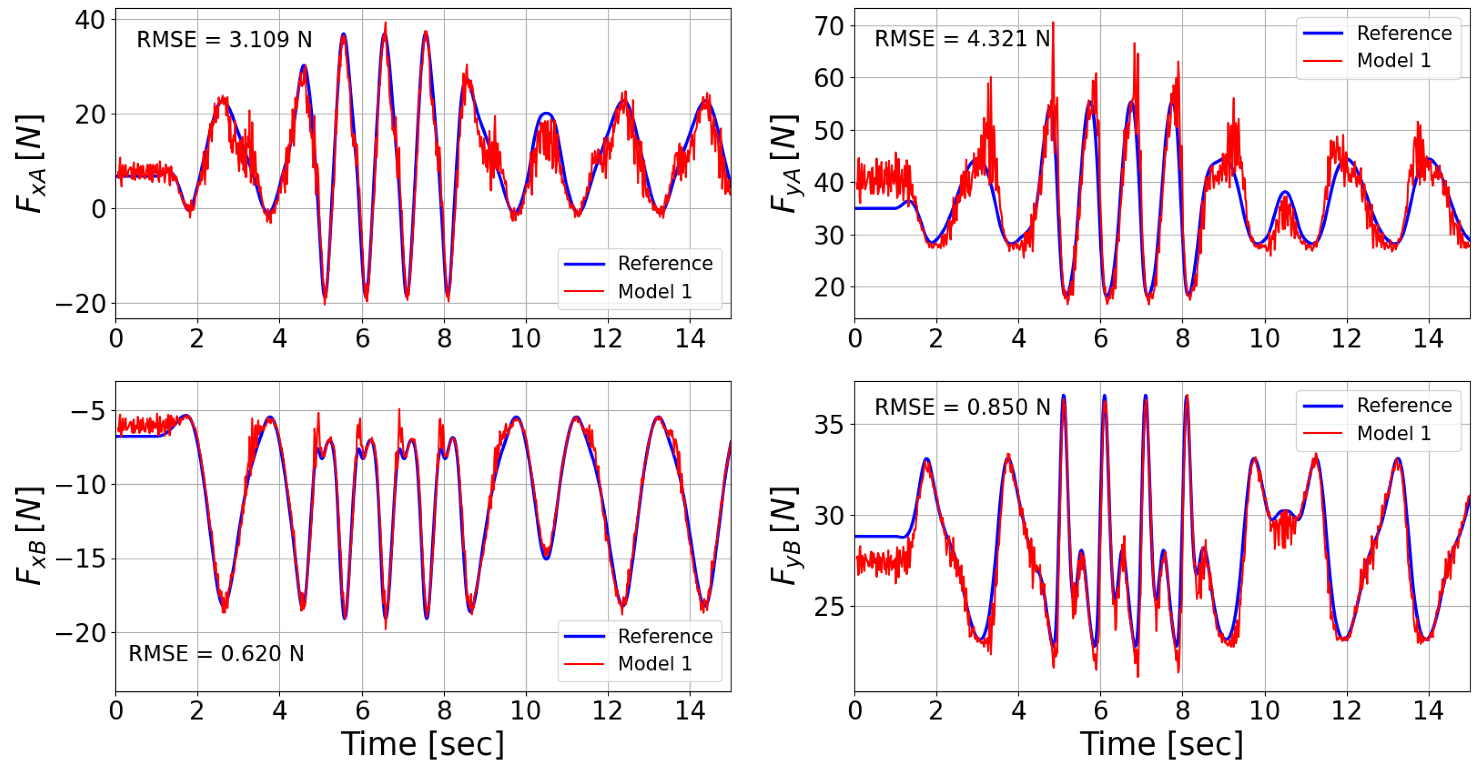
| Model 1 | 3.109 | 4.321 | 0.620 | 0.850 |
| Model 2 | 2.384 | 1.404 | 0.534 | 0.533 |
Disclaimer/Publisher’s Note: The statements, opinions and data contained in all publications are solely those of the individual author(s) and contributor(s) and not of MDPI and/or the editor(s). MDPI and/or the editor(s) disclaim responsibility for any injury to people or property resulting from any ideas, methods, instructions or products referred to in the content. |
© 2024 by the authors. Licensee MDPI, Basel, Switzerland. This article is an open access article distributed under the terms and conditions of the Creative Commons Attribution (CC BY) license (https://creativecommons.org/licenses/by/4.0/).
Share and Cite
Fabiocchi, D.; Giulietti, N.; Carnevale, M.; Giberti, H. AI-Driven Virtual Sensors for Real-Time Dynamic Analysis of Mechanisms: A Feasibility Study. Machines 2024, 12, 257. https://doi.org/10.3390/machines12040257
Fabiocchi D, Giulietti N, Carnevale M, Giberti H. AI-Driven Virtual Sensors for Real-Time Dynamic Analysis of Mechanisms: A Feasibility Study. Machines. 2024; 12(4):257. https://doi.org/10.3390/machines12040257
Chicago/Turabian StyleFabiocchi, Davide, Nicola Giulietti, Marco Carnevale, and Hermes Giberti. 2024. "AI-Driven Virtual Sensors for Real-Time Dynamic Analysis of Mechanisms: A Feasibility Study" Machines 12, no. 4: 257. https://doi.org/10.3390/machines12040257
APA StyleFabiocchi, D., Giulietti, N., Carnevale, M., & Giberti, H. (2024). AI-Driven Virtual Sensors for Real-Time Dynamic Analysis of Mechanisms: A Feasibility Study. Machines, 12(4), 257. https://doi.org/10.3390/machines12040257