Article

The Influence of the Setup on the Result of Measuring the Roundness of an Anuloid Surface

Institute of Production Technologies, Faculty of Materials Science and Technology in Trnava, Slovak University of Technology in Bratislava, 917 24 Trnava, Slovakia
*
Author to whom correspondence should be addressed.
Machines 2024, 12(4), 258; https://doi.org/10.3390/machines12040258
Submission received: 13 March 2024 / Revised: 3 April 2024 / Accepted: 8 April 2024 / Published: 12 April 2024
(This article belongs to the Special Issue Precision Manufacturing and Machine Tools)

Abstract

:
In engineering practice, anuloid surfaces are produced that are subject to strict requirements in terms of accuracy (e.g., in the bearing industry). Roundness is also often measured. The accuracy of the roundness measurement does not only depend on the accuracy of a particular metrological system. The setting of the component on the measuring device can also have a significant influence on the accuracy of the measurement. The axis of the measured surface must be perpendicular to the section in which the roundness is measured. Tilting the measured surface causes a systematic measurement error, which depends on the size of the tilt angle and the parameters of the measured surface. This study presents mathematical relations for the calculation of this error when measuring roundness on an anuloid surface. Mathematical relations for the internal and external surfaces formed by the inner and outer parts of the anuloid are derived herein. There is also a theoretical analysis of the influence of inclination and the parameters of the measured surface on the size of this error. Theoretically calculated values were compared with practically measured values of roundness. The error had a negative effect on the accuracy of the roundness measurement. It affected the roundness value, the second harmonic component, and also the roundness profile itself.

Graphical Abstract

1. Introduction

Measurement accuracy refers to how closely a measured quantity aligns with its true value, often influenced by calibration errors. In their discussion, the authors of [1] emphasize the significance of precision in both process control and product quality. They assert that precision holds the utmost importance in process control measurement as neglecting accuracy can profoundly affect a manufacturer's ability to effectively regulate processes. The metalworking industry places significant importance on acquiring tools that enhance measurement accuracy as they aid quality control, bolster reliability, and promote the goal of achieving correct results from the outset.
In the evolving landscape of global business, the necessity for measurement accuracy has heightened due to the potential time and cost savings it offers. Cylindrical components play a crucial role in engineering products, with roundness serving as a pivotal form of tolerance [2,3].
Imperfections in manufacturing can lead to varying roundness tolerances across parts, making the precision and reliability of roundness measurement essential, particularly in precision and ultraprecision scenarios [4].
In reference [5], a correlation calculus was employed to measure and comparatively evaluate the roundness profiles and roundness deviation values of the bearing journals on the main crankshaft of a medium-speed marine engine. The proposed system offered the capability of assessing the form deviations and axis positions of cylindrical surfaces, including straight shafts and crankshafts.
According to reference [6], non-contact measuring instruments are preferred when determining the size and geometry errors of high-precision components. This preference arises from the fact that mechanical measuring instruments can induce deformations, thereby compromising the accuracy of the results. Consequently, optical, optoelectronic, laser, and similar devices are extensively utilized for this purpose, as noted in references [7,8,9,10].
Many researchers have investigated bearing misalignment, its causes, and its impact on durability and performance. For example, Prabhu [11] performed an experimental investigation on misalignment effects on journal (radial) bearings. Bouyer and Fillon [12] provided an experimental analysis of misalignment effects on hydrodynamic plain journal bearing performance. Howard [13] conducted an experimental study on misalignment in gas foil journal bearings. Shi, Cao, and Chen [14] investigated the effect of angular misalignment on the dynamic characteristics of externally pressurized air journal bearings. Ma et al. [15] modelled a non-Gaussian surface and misalignment for the condition monitoring of journal bearings. Oktaviana, Tong, and Hong [16] used a skidding analysis of an angular contact ball subjected to a radial load and angular misalignment. Yang, Zhangs, and Li [17] provided a wear analysis of an angular contact ball bearing in a multiple-bearing spindle system subjected to uncertain initial angular misalignment. Ye, Wang, Gu, and Zhang [18] evaluated the effects of tilted misalignment on the loading characteristics of cylindrical roller bearings. Tong and Hong [19] investigated the fatigue life of a tapered roller bearing subject to angular misalignment. Zhao, Wang, and Hou [20] obtained measurements of the roller tilt angle in a double-row tapered roller bearing with strain gauges. Šimunović and Baršić evaluated the spindle error of a roundness measurement device [21]. The measurement of small cylinders with high accuracy was investigated by Li et al. [22]. Tiainen and Viitala studied the effect of positional errors on the accuracy of roundness measurements [23].
The above-mentioned authors concluded that misalignment in bearings could cause significant issues in terms of the performance and durability of bearings. To prevent misalignment and improper assembly, ascertaining the correct dimensions of every bearing component is necessary. However, if the measuring process is not correct (e.g., incorrect setup), a suitable component could be excluded and an improper component could be included in the assembly process, causing misalignment and improper assembly.
From the reviewed articles and also from our own experience, it is clear that high accuracy when measuring some components is essential for their proper functioning. One such component is a ball bearing, where (due to its functionality and service life) high demands are placed on the anuloid surface of the inner and outer rings. For its optimal measurement, its perfect setting is necessary. However, perfection is unattainable, and an incorrect setting can lead to incorrect measurements that could lead to the discarding of the correct piece. This imperfect setting is reflected in the inclination of the part. Therefore, this study aimed to predict and quantify the inaccuracies created by this inclination. For this purpose, mathematical equations were derived to calculate the error rate on the inner and outer anuloid surfaces.

2. Materials and Methods

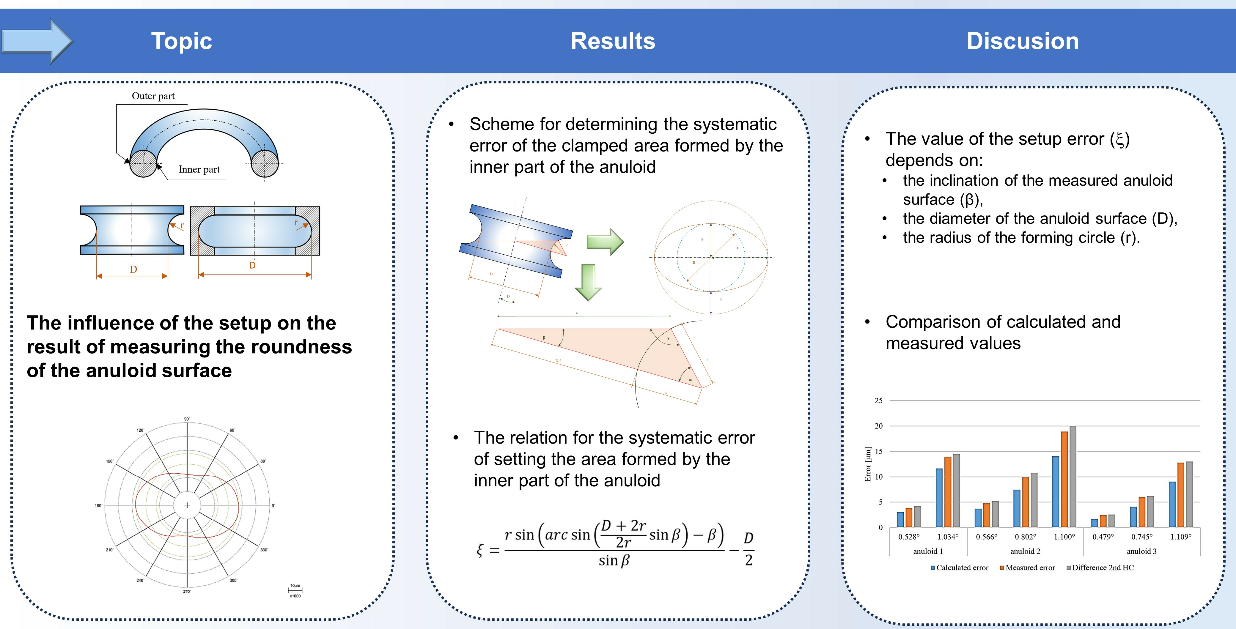
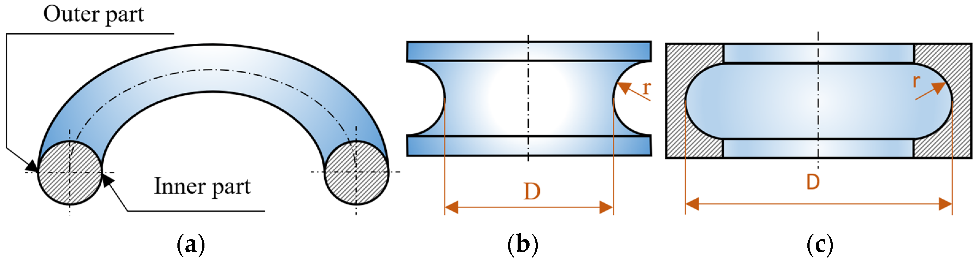
Defining the Problem

In practice, anuloid surfaces are also produced on the components (Figure 1). These surfaces can be internal or external. However, which part of the anuloid they are made of—the inner or outer part—is also important. These surfaces are often subject to strict requirements in terms of accuracy (e.g., in the bearing industry). Roundness is also often measured. The accuracy of roundness measurements does not only depend on the accuracy of a particular metrological system. The setting of the component on the measuring device can also have a significant influence on the accuracy of the measurement.
The correct setting of the measured surface in a metrological system is an important condition when measuring roundness. The measured roundness profile must lie in a plane that is perpendicular to the axis of the measured surface. In this case, the measured profile corresponds with the actual profile. Even the measured roundness value corresponds with the actual roundness. However, when the measured part is mechanically clamped (set up) to a round gauge, the measured surface may be incorrectly set. Undesirable tilting of the measured surface may occur; thus, the axis of the measurement is not identical to the axis of the part.
An incorrect setting, or tilting the measured surface, changes the measured roundness profile. On an ideal anuloid surface, the roundness profile has the shape of a circle (with the correct setting of the measured surface, where the axis of the surface is perpendicular to the measuring plane). After tilting the measured surface, a roundness profile is created, which has the shape of an ellipse (Figure 2). This also changes the measured roundness result. We concluded that there would be an error that was mathematically dependent on the size of the tilt of the measured surface (the larger the tilt angle, the larger the error). The error would have the characteristic of a systematic error and, therefore, we could characterize it as a systematic error of setting—an error caused by the inaccurate setting of the measured surface on the measuring device.

3. Results

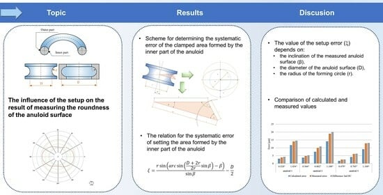
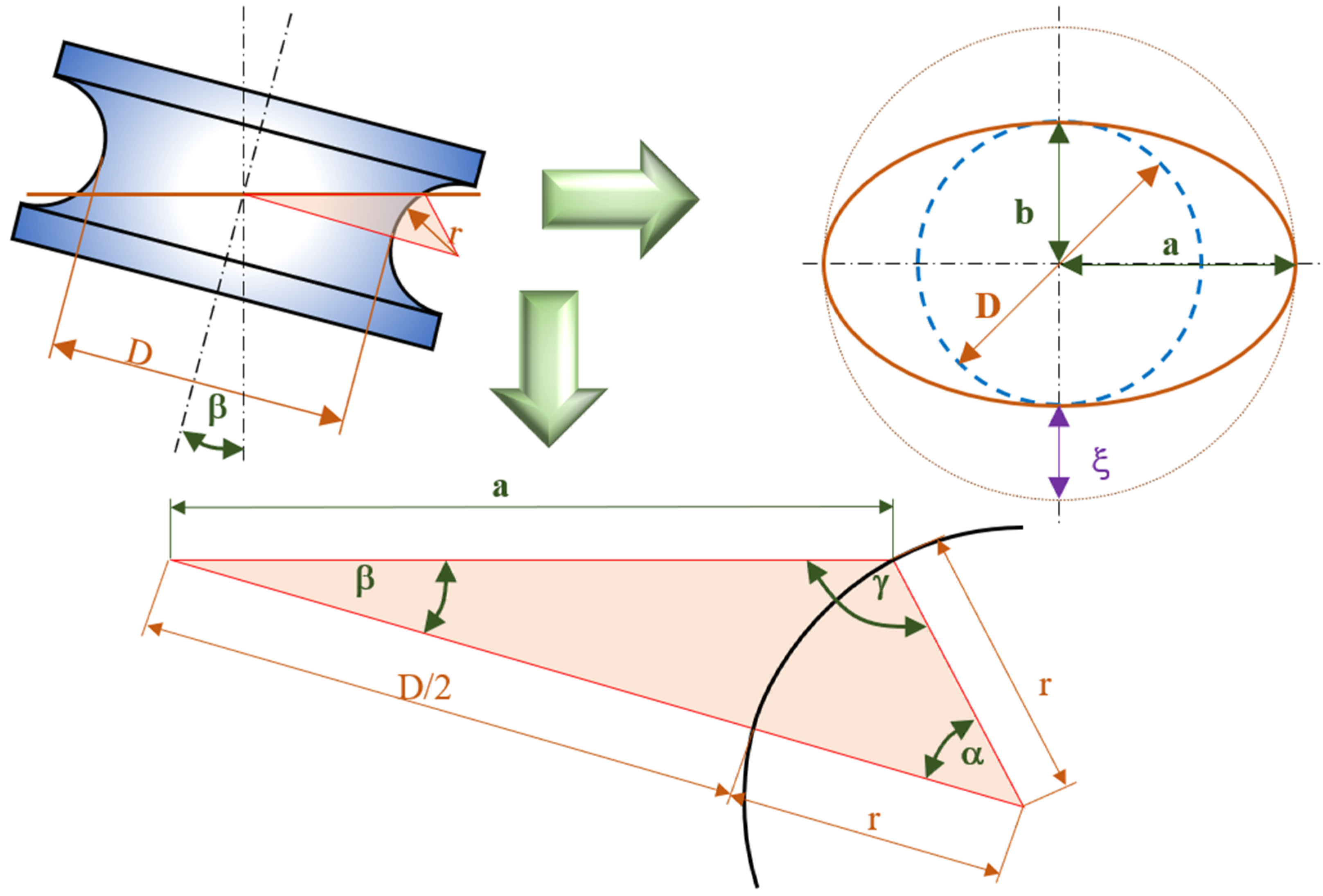
3.1. Calculation of the Systematic Error of the Clamped Area Formed by the Inner Part of the Anuloid

The systematic error of setup for an ideal anuloid surface can be mathematically expressed as the difference between the semi-major and semi-minor axes of the ellipse, as seen in Figure 3.
ξ = a b
The value of the semi-minor axis of the ellipse is equal to the radius of the measured anuloid surface:
b = D 2
When calculating the semi-major axis of the ellipse, it is necessary to start from the triangle, which is created during tilting (Figure 3). We used the sine theorem:
a sin α = r sin β = D 2 + r sin γ
Using gradual modifications, we obtained:
γ = a r c sin D + 2 r 2 r sin β
Considering that angle γ is an obtuse angle and sin(γ) = sin(180 − γ), we could modify this:
γ = 180 a r c sin D + 2 r 2 r sin β
The sum of the angles in a triangle is 180°, so:
α = 180 β γ
After editing, this became:
α = a r c sin D + 2 r 2 r sin β β
From sine theorem (3), we also obtained:
a = r sin α sin β
By substituting relation (7) into relation (8), we obtained:
a = r sin a r c sin D + 2 r 2 r sin β β sin β
The relation for the systematic error of setting the area formed by the inner part of the anuloid was obtained by substituting relation (9) and (2) into relation (1):
ξ = r sin a r c sin D + 2 r 2 r sin β β sin β D 2
Relation (9) applies to the calculation of the systematic error of setting the outer and inner surface, which is formed by the inner part of the anuloid. This systematic error is dependent on the diameter of the anuloid surface “D”, the radius of the forming circle “r”, and the angle of inclination “β” of the measured surface. Figure 4 graphically presents the dependence of the calculated systematic error of setting the anuloid surface (formed by the inner part of the anuloid) on the diameter of the surface. A radius of the forming circle of r = 5 mm was considered here. As the surface diameter increased, the error caused also increased.
The effect of the radius of the forming circle on the caused error is presented in Figure 5. A diameter of the anuloid surface of D = 50 mm was considered here. As the radius of the forming circle decreased, the error caused increased.

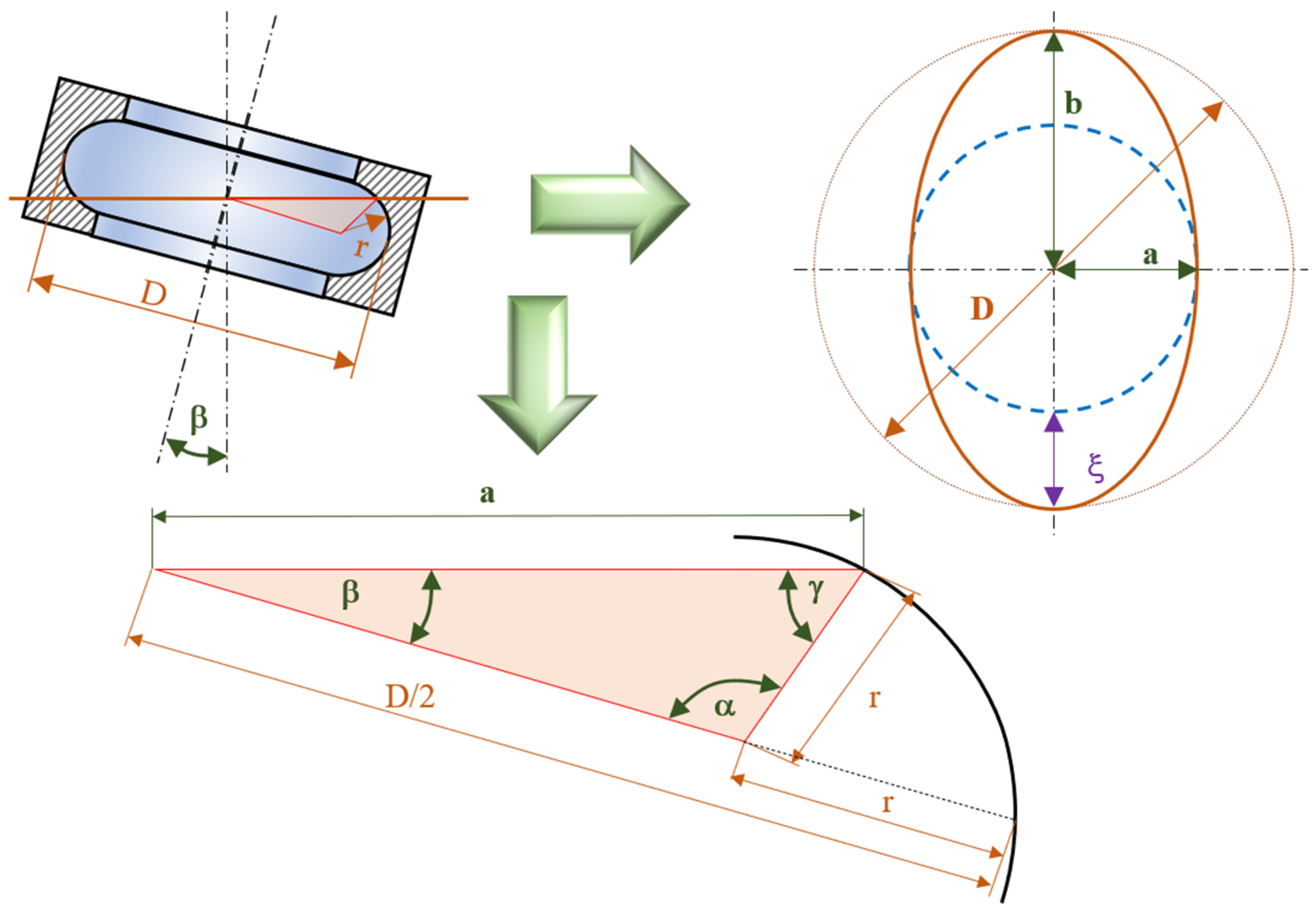
3.2. Calculation of the Systematic Error of the Clamped Area Formed by the Outer Part of the Anuloid
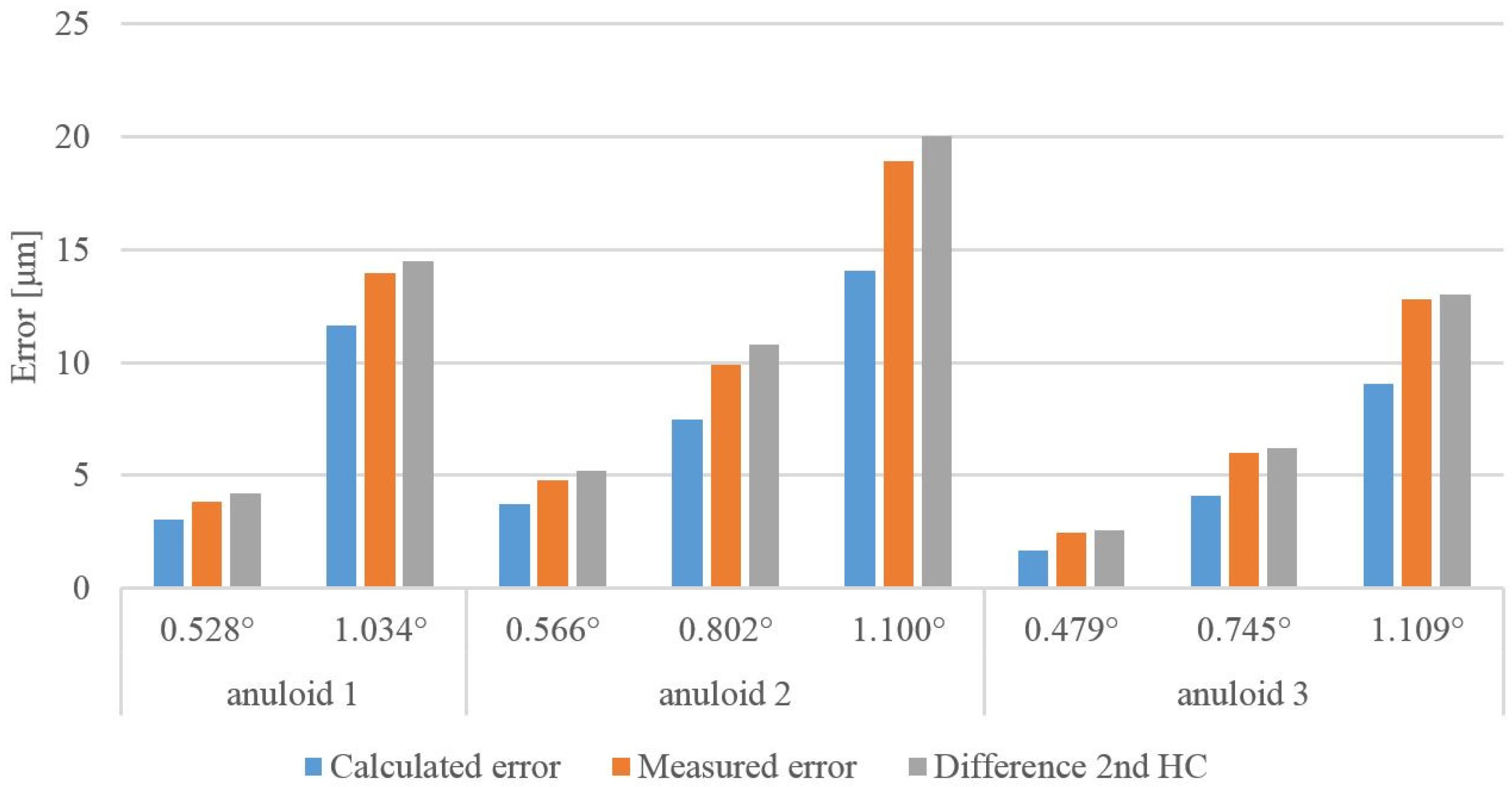
The systematic error of setup for an ideal anuloid surface can be mathematically expressed as the difference between the semi-major and semi-minor axes of the ellipse, as seen in Figure 6.
ξ = b a
The value of the semi-major axis of the ellipse is equal to the radius of the measured anuloid surface:
b = D 2
When calculating the semi-minor axis of the ellipse, it is necessary to start from the triangle, which is created during tilting (Figure 6). Similar to the previous case, we used the sine theorem. Using gradual modifications, we obtained:
γ = a r c sin D 2 r 2 r sin β
The sum of the angles in a triangle is 180°, so:
α = 180 β γ = 180 β a r c sin D 2 r 2 r sin β
From the sine theorem we also obtained:
a = r sin α sin β
By substituting relation (14) into relation (15), we obtained:
a = r sin 180 β a r c sin D 2 r 2 r sin β sin β
The relation for the systematic error of setting the area formed by the outer part of the anuloid was obtained by substituting relation (16) and (12) into relation (11):
ξ = D 2 r sin 180 β a r c sin D 2 r 2 r sin β sin β
Relation (17) applies to the calculation of the systematic error of setting the outer and inner surface, which is formed by the outer part of the anuloid. This systematic error is dependent on the diameter of the anuloid surface “D”, the radius of the forming circle “r”, and the angle of inclination “β” of the measured surface. Figure 7 graphically presents the dependence of the calculated systematic error of setting the anuloid surface (formed by the outer part of the anuloid) on the diameter of the surface. A radius of the forming circle of r = 5 mm was considered here. As the surface diameter increased, the error caused also increased.
The effect of the radius of the forming circle on the caused error is presented in Figure 8. A diameter of the anuloid surface of D = 50 mm was considered here. As the radius of the forming circle decreased, the error caused increased.

4. Discussion

Comparison of Calculated and Measured Values

For a practical check of the derived mathematical relations, roundness was measured using real anuloid surfaces. The components were the inner rings of a ball bearing (Figure 9a), which had outer surfaces formed by the inner part of the anuloid. The measurements were obtained using a Rondcom 60 A round gauge (Accretech, Tokyo, Japan; Figure 9b). A component was clamped onto the measuring table of the device. The measured surface was centered and leveled in automatic mode so that the measurement plane was perpendicular to the axis of the part. The roundness was then measured. The parameters for the roundness measurement and evaluation were as follows:
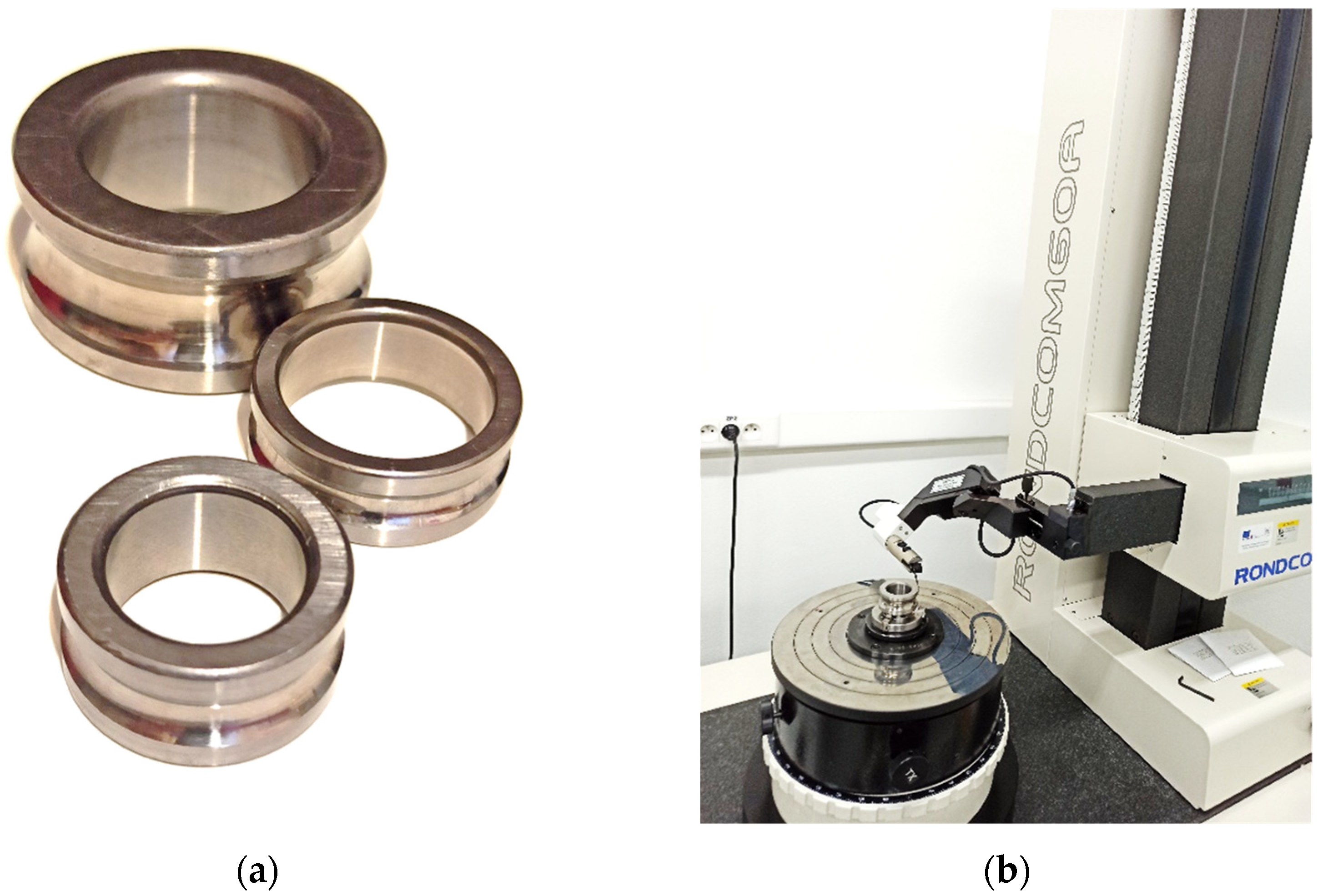
  • Rotation precision: (0.02 + 6 H/10,000) µm (H is the height from the table top to the measuring point in mm).
  • Number of measured points for the roundness measurement: 3600.
  • Method of roundness evaluation: MZC (the minimum zone circle).
  • The filter used to evaluate the roundness was a Gauss low 150 UPR (undulations per revolution).
  • Measurement speed (rotation): 4.0 min−1.
The round gauge enabled the tilting of the measuring table. This allowed the part to be tilted. The measurement plane was thus inclined and was not perpendicular to the axis of the part. The size of the angle of inclination was measured using the touch probe of the round gauge. The part was re-centered and the roundness of the inclined surface was measured. The change in roundness was observed as follows:
Measured error = roundness of the inclined surface − roundness of the leveled surface
A comparison of the measured error with calculated systematic error (calculated error) is presented in Table 1. A harmonic analysis was also performed on the roundness profiles. This is a tool that decomposes a roundness profile into simple harmonic functions. The application of the harmonic analysis (Fourier series) to roundness is described in [24]. As an ellipse is created when an anuloid surface is tilted, it can be assumed that the systematic error of the tilt is manifested by a significant increase in the value of the second harmonic component. With such a profile, the roundness would be equal to twice the amplitude. Therefore, in the calculations, a double value of the second harmonical component (2nd HC) must be considered. We assumed that twice the value of the increase in the second harmonic component would be approximately equal to the systematic tilt error. This inclination should not have such a significant effect on the other components.
Difference 2nd HC = 2 · 2nd HC of the inclined surface − 2 · 2nd HC of the leveled surface
The measurement was carried out on three surfaces:
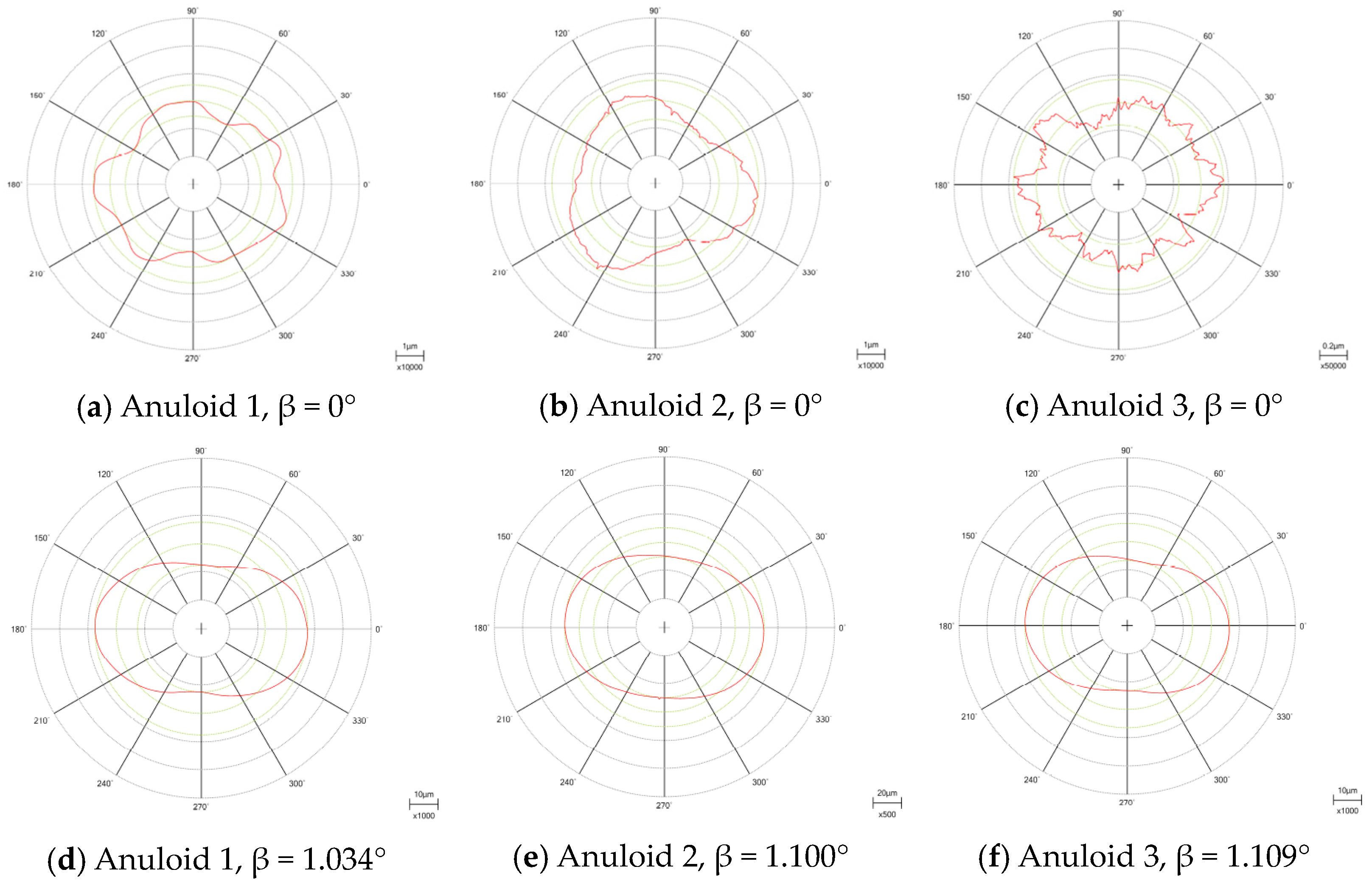
  • Anuloid 1: surface diameter D = 29.3 mm and radius of the forming circle r = 3.5 mm; the measured profiles are presented in Figure 10a,d.
  • Anuloid 2: surface diameter D = 26.5 mm and radius of the forming circle r = 5 mm; the measured profiles are presented in Figure 10b,e.
  • Anuloid 3: surface diameter D = 42.5 mm and radius of the forming circle r = 9 mm; the measured profiles are presented in Figure 10c,f.
Figure 11 shows a graphical comparison of the calculated error, measured error (difference between real measured roundness), and 2nd HC difference. The calculated error values corresponded with the actual differences between the values before tilting and after tilting. The real values of the measured error and 2nd HC difference were greater than the theoretical values. This was because the theoretical error values were calculated for an ideal anuloid surface, or a surface with absolute roundness (roundness = 0 μm). However, this cannot be achieved on a real surface; thus, the real results could only approximate the calculated values.

5. Conclusions

In this article, mathematical relations were derived for the calculation of a systematic error caused by the inappropriate setting of a measured area on a round gauge. Mathematical relations were applied to both the external and internal surfaces created by the external or internal segment of the anuloid. This was the main goal of the article. The validity of the relationships was also confirmed by the results from the practical measurement. We concluded that the theoretically derived mathematical relations for anuloid surfaces corresponded with the real measured values. We can also make the following statements:
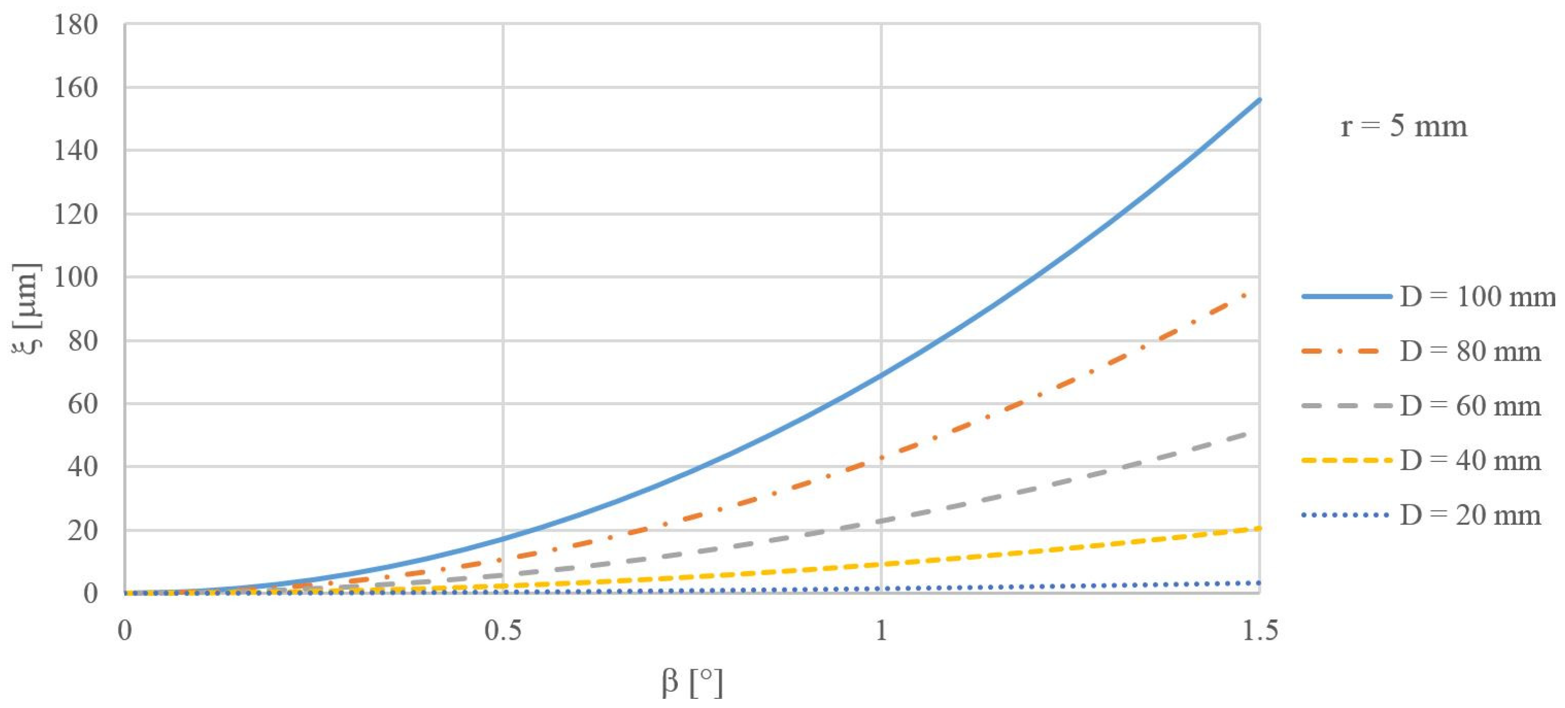
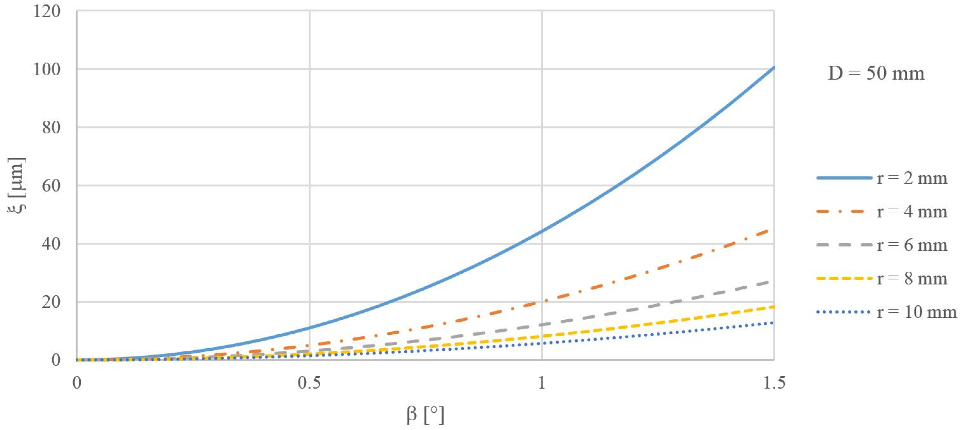
  • The value of the setup error (ξ) depended on:
    the inclination of the measured anuloid surface (β);
    the diameter of the anuloid surface (D);
    the radius of the forming circle (r).
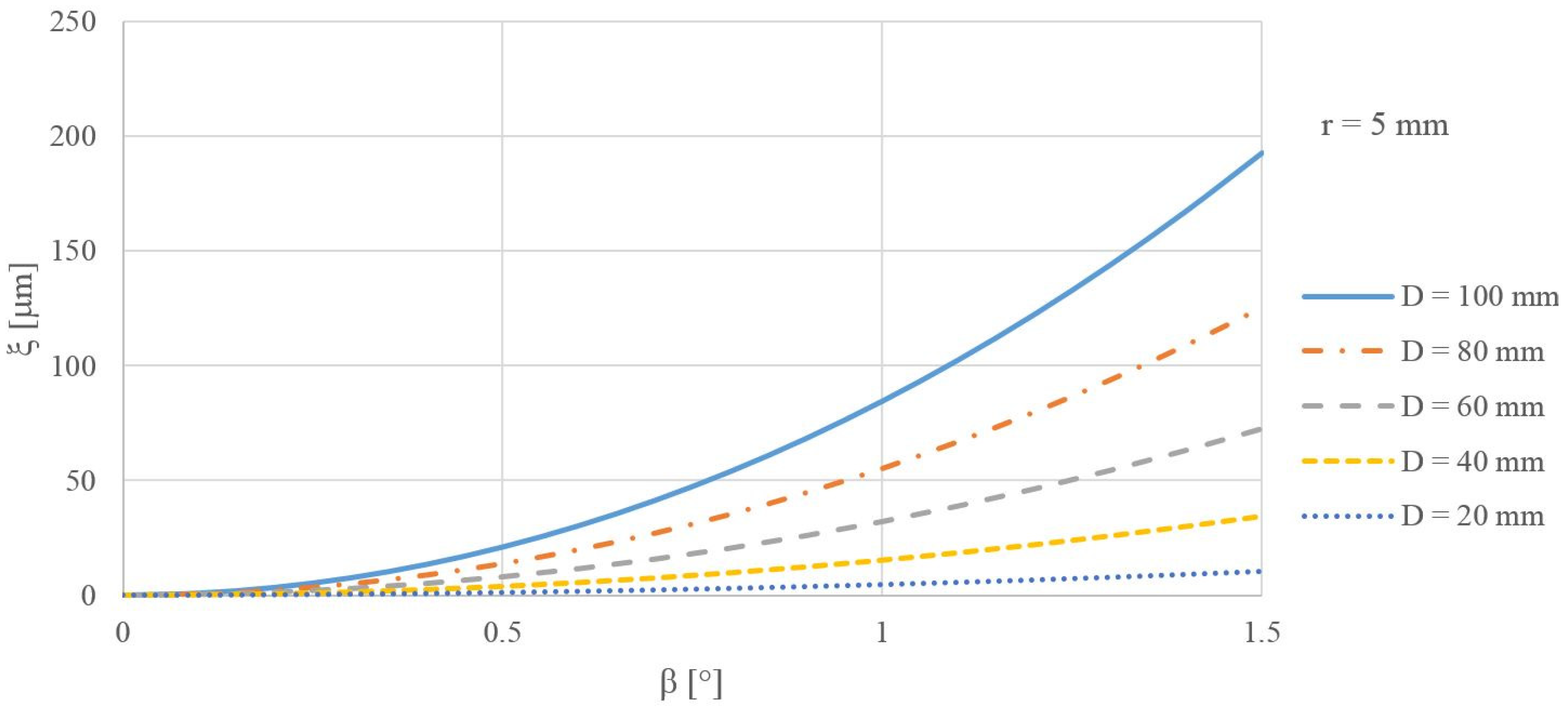
  • As the angle of inclination of the measured surface (β) increased, the calculated error also increased.
  • As the diameter of the measured area (D) increased, the calculated error also increased.
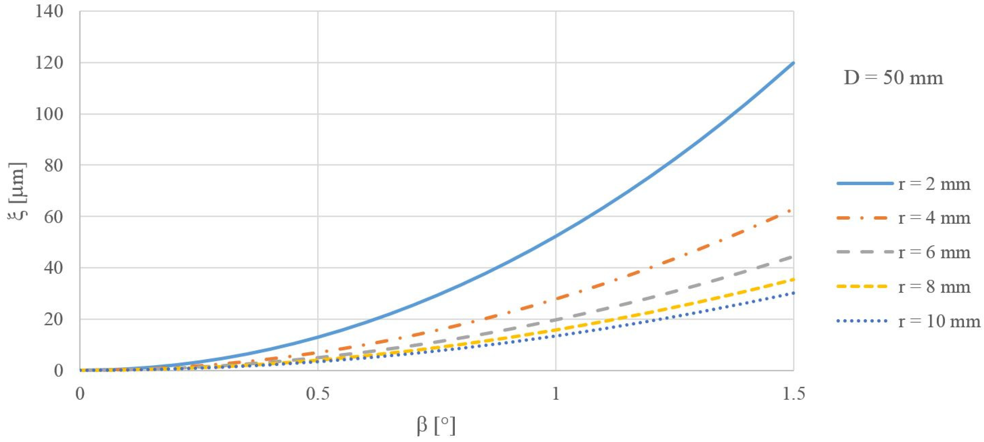
  • As the radius of the forming circle (r) increased, the calculated error decreased.
The tilt of the measured surface negatively affected the accuracy of the roundness measurement. After tilting, the roundness profile was elliptical; tilting also affected the measured roundness profile. However, if the roundness profile was elliptical and the inclination was in the direction of the semi-minor axis of the ellipse, then the inclination of such a surface could reduce the measured roundness. Then, the accuracy of the measurement was affected in the opposite way; a smaller roundness than was actually measured on the surface was calculated. Such a case is analyzed in [25].
Modern round gauges automatically determine the angle of inclination and level the position of the measured surface, even before the actual measurement; thus, they measure the correct profile. Older round gauges cannot detect this angle, so the operator must detect this angle and make the necessary adjustments to the position of the measured surface. Most round gauge software is not open-source, so the implementation of derived formulas serves to manually derive the inclination of older round gauges. The verification of inclination is determined by the software of modern round gauges.

Author Contributions

Conceptualization, A.G.; methodology, A.G.; software, A.G.; validation, A.G.; formal analysis, A.G.; investigation, A.G.; resources, M.K.; data curation, A.G.; writing—original draft preparation, A.G.; writing—review and editing, M.K.; visualization, A.G.; supervision, M.K.; project administration, M.K.; funding acquisition, M.K. All authors have read and agreed to the published version of the manuscript.

Funding

This research received no external funding.

Data Availability Statement

The data presented in this study are available on request from the corresponding author. The data are not publicly available due to the large data capacity.

Conflicts of Interest

The authors declare no conflicts of interest.

References

  1. Askary, F.; Sullivan, N. Importance of measurement accuracy in statistical process control. In Proceedings of the Metrology, Inspection, and Process Control for Microlithography XIV, Santa Clara, CA, USA, 27 February–3 March 2000; Volume 3998. [Google Scholar] [CrossRef]
  2. Whitehouse, D.J. Surface metrology. Meas. Sci. Technol. 1997, 8, 955–972. [Google Scholar] [CrossRef]
  3. Muralikrishnan, B.; Raja, J. Computational Surface and Roundness Metrology; Springer: London, UK, 2009; ISBN-13:9781848002968. [Google Scholar]
  4. Sun, C.; Wang, L.; Tan, J.; Zhao, B.; Zhou, T.; Kuang, Y. A high-accuracy roundness measurement for cylindrical components by a morphological filter considering eccentricity, probe offset, tip head radius and tilt error. Meas. Sci. Technol. 2016, 27, 085008. [Google Scholar] [CrossRef]
  5. Nozdrzykowski, K.; Janecki, D. Comparative studies of reference measurements of cylindrical surface roundness profiles of large machine components. Metrol. Meas. Syst. 2014, 21, 67–76. [Google Scholar] [CrossRef]
  6. Kupriyanov, O. The influence of measurement error on the risks of the consumer and the manufacturer when completing connections. Ukr. J. Mech. Eng. Mater. Sci. 2020, 6, 22–29. [Google Scholar] [CrossRef]
  7. Aston, R.; Davis, J.; Stout, K. A probing question: A customer’s investigation into the directional variability of a coordinate measuring machine touch trigger probe. Int. J. Mach. Tools Manuf. 1997, 10, 1375–1382. [Google Scholar] [CrossRef]
  8. Desa, D.O.J. Instrumentation Fundamentals for Process Control; CRC Press: Boca Raton, FL, USA, 2001; p. 566. ISBN 9781560329015. [Google Scholar]
  9. Ostrowska, K.; Gaska, A.; Sladek, J. Determining the uncertainty of measurement with the use of a Virtual Coordinate Measuring Arm. Int. J. Adv. Manuf. Technol. 2014, 71, 529–537. [Google Scholar] [CrossRef]
  10. Blanco, D.; Valino, G.; Fernandez, P.; Rico, C.; Mateos, S. Influence of part material and sensor adjustment on the quality of digitised point-clouds using conoscopic holography. Precis. Eng. 2015, 42, 42–52. [Google Scholar] [CrossRef]
  11. Prabhu, B.S. An experimental investigation on the misalignment effects in journal bearings. Tribol. Trans. 1997, 40, 235–242. [Google Scholar] [CrossRef]
  12. Bouyer, J.; Fillon, M. An experimental analysis of misalignment effects on hydrodynamic plain journal bearing performances. In: Journal of Tribology. Am. Soc. Mech. Eng. 2002, 127, 313–319. [Google Scholar] [CrossRef]
  13. Howard, S.A. Misalignment in gas foil journal bearings: An experimental study. In: Journal of Engineering for Gas Turbines and Power. Am. Soc. Mech. Eng. 2009, 1, 741–749. [Google Scholar] [CrossRef]
  14. Shi, J.; Cao, H.; Chen, X. Effect of angular misalignment on the dynamic characteristics of externally pressurized air journal bearing. J. Eng. Tribol. Proc. Inst. Mech. Eng. 2019, 234, 205–228. [Google Scholar] [CrossRef]
  15. Ma, J.; Fu, C.; Zhang, H.; Chu, F.; Shi, Z.; Gu, F.; Ball, A.D. Modelling non-Gaussian surfaces and misalignment for condition monitoring of journal bearings. Measurement 2021, 174, 108983. [Google Scholar] [CrossRef]
  16. Oktaviana, L.; Tong, V.-C.; Hong, S.-W. Skidding analysis of angular contact ball bearing subjected to radial load and angular misalignment. J. Mech. Sci. Technol. 2019, 33, 837–845. [Google Scholar] [CrossRef]
  17. Yang, Z.; Zhang, Y.; Zhang, K.; LI, S. Wear analysis of angular contact ball bearing in multiple-bearing spindle system subjected to uncertain initial angular misalignment. In: Journal of Tribology. Am. Soc. Mech. Eng. 2021, 143, 091703. [Google Scholar] [CrossRef]
  18. Ye, Z.; Wang, L.; Gu, L.; Zhang, C. Effects of tilted misalignment on loading characteristics of cylindrical roller bearings. Mech. Mach. Theory 2013, 69, 153–167. [Google Scholar] [CrossRef]
  19. Tong, V.-C.; Hong, S.-W. The effect of angular misalignment on the running torques of tapered roller bearings. Tribol. Int. 2016, 95, 76–85. [Google Scholar] [CrossRef]
  20. Zhao, Z.; Wang, X.; Hou, Y. Measurement of the roller tilt angle in a double-row tapered roller bearing with strain gauges. Measurement 2024, 226, 114106. [Google Scholar] [CrossRef]
  21. Šimunović, V.; Baršić, G. Evaluating the spindle error of the roundness measurement device. Meas. Sens. 2024, 32, 101038. [Google Scholar] [CrossRef]
  22. Li, Q.; Shimizu, Y.; Wang, X.; Li, X.; Gao, W. High-accuracy roundness measurement of small cylindrical workpieces by a high-frequency filtering method. Precis. Eng. 2024, 85, 241–246. [Google Scholar] [CrossRef]
  23. Tiainen, T.; Viitala, R. Effect of positional errors on the accuracy of multi-probe roundness measurement methods. Mech. Syst. Signal Process. 2020, 144, 106883. [Google Scholar] [CrossRef]
  24. Görög, A.; Görögová, I. Application of Fourier series for evaluation of roundness profiles in metrology. Adv. Sci. Technol. Res. J. 2019, 13, 30–38. [Google Scholar] [CrossRef]
  25. Görög, A. Influence of the Setting on the Result of Measuring the Roundness of the Cylindrical and Conical Surface. Manuf. Technol. 2022, 22, 408–413. [Google Scholar] [CrossRef]
Figure 1. Anuloid surfaces: (a) anuloid; (b) outer surface formed by the inner part of the anuloid; (c) inner surface formed by the outer part of the anuloid. D: diameter of the anuloid surface; r: radius of the forming circle.
Machines 12 00258 g001
Figure 2. Roundness profile when measuring correctly and incorrectly clamped anuloid surfaces.
Machines 12 00258 g002
Figure 3. Scheme to determine the systematic error of a clamped area formed by the inner part of an anuloid. D: diameter of the measured anuloid surface; r: radius of the forming circle; a: semi-major axis of the ellipse (roundness profile); b: semi-minor axis of the ellipse (roundness profile); ξ: systematic error of the setting.
Machines 12 00258 g003
Figure 4. The size of the error ξ for different tilts β and diameters D of the area formed by the inner part of the anuloid.
Machines 12 00258 g004
Figure 5. The size of the error ξ for different tilts β and radii of the forming circle r of the surface formed by the inner part of the anuloid.
Machines 12 00258 g005
Figure 6. Scheme to determine the systematic error of a clamped area formed by the outer part of an anuloid. D: diameter of the measured anuloid surface; r: radius of the forming circle; a: semi-minor axis of the ellipse (roundness profile); b: semi-major axis of the ellipse (roundness profile); ξ: systematic error of the setting.
Machines 12 00258 g006
Figure 7. The size of the error ξ for different tilts β and diameters D of the area formed by the outer part of the anuloid.
Machines 12 00258 g007
Figure 8. The size of the error ξ for different tilts β and radii of the forming circle r of the surface formed by the outer part of the anuloid.
Machines 12 00258 g008
Figure 9. Experimental setup: (a) measured parts; (b) round gauge Rondcom 60 A.
Machines 12 00258 g009
Figure 10. Roundness profiles measured on the surface formed by the inner anuloid (β: inclination angle).
Machines 12 00258 g010
Figure 11. The comparison of calculated and measured values.
Machines 12 00258 g011
Table 1. Measured and calculated values.
SurfaceTilt β (°)Roundness (μm)2nd HC (μm)Calculated Error (μm)Measured Error (μm)Differ. 2nd HC (μm)
Anuloid 101.3960.278---
Anuloid 10.5285.2072.3683.0343.8114.180
Anuloid 11.03415.3577.51011.64413.96114.464
Anuloid 201.4370.193---
Anuloid 20.5666.2432.7813.7104.8065.176
Anuloid 20.80211.3365.5807.4549.89910.774
Anuloid 21.10020.36610.21514.04218.92920.044
Anuloid 300.3280.056---
Anuloid 30.4792.7771.3331.6912.4492.554
Anuloid 30.7456.3053.1534.0915.9776.194
Anuloid 31.10913.1396.5499.07312.81112.986
Disclaimer/Publisher’s Note: The statements, opinions and data contained in all publications are solely those of the individual author(s) and contributor(s) and not of MDPI and/or the editor(s). MDPI and/or the editor(s) disclaim responsibility for any injury to people or property resulting from any ideas, methods, instructions or products referred to in the content.

