Article

High-Efficient Direct Power Control Scheme Using Predictive Virtual Flux for Three-Phase Active Rectifiers

1
School of Electrical and Electronics Engineering, Chung-Ang University, Seoul 06974, Republic of Korea
2
Department of Electrical and Computer Engineering, Mississippi State University, Starkville, MS 39762, USA
*
Author to whom correspondence should be addressed.
Machines 2024, 12(5), 290; https://doi.org/10.3390/machines12050290
Submission received: 29 February 2024 / Revised: 21 April 2024 / Accepted: 23 April 2024 / Published: 26 April 2024

Abstract

:
In recent years, the pulse-width-modulation (PWM) converter has been found to have extensive applications in renewable energy, industrial fields, and others. The high efficiency requirement is crucial to operating a PWM rectifier in various applications, in addition to the fundamental control objectives of sinusoidal grid currents and the correct DC bus voltage. Additionally, in practical application, another issue arises when the grid voltage frequently experiences distortion, leading to a distorted grid current and a significant rise in total harmonic distortion (THD). To resolve these problems, a model predictive virtual flux-based direct power control (MPVFDPC) with improved power loss performance is proposed based on an integrated switching state predetermination strategy. The proposed MPVFDPC for PWM rectifier inherits the merits of both virtual flux control and direct power control, which have fast dynamic performance and the grid current THD is considerably decreased under distorted grid voltage states. The proposed technique aims to minimize switching loss under ideal and distorted grid voltage states by exploiting the discontinuous modulation concept by using a switching state predetermination strategy. The MPVFDPC with switching state predetermination strategy is proven by employing it in experiments as well as simulations in comparison with previous models: predictive direct power control (Conv. MPDPC) and conventional MPVFDPC (Conv. MPVFDPC). The acquired waveforms and quantitative data are employed to prove the effectiveness of the developed algorithm.

1. Introduction

Modern voltage source rectifiers (VSR) with pulse width modulation (PWM) possess several merits, including the possibility of bidirectional power exchange, power factor adjustment and sinusoidal current waveforms [1,2,3,4]. In areas of the ac-dc converters, simple diode rectifiers without PWM operation had been popularly employed instead of the ac-dc converter with PWM techniques. However, recently, PWM converters for ac-dc power conversion have started to be widely used in the applications of renewable energy and other industrial fields, due to their ability to provide bi-directional power flow. Typically, two extensively studied methods for controlling PWM rectifiers are direct power control (DPC) [5] and voltage-oriented control (VOC) [6]. VOC techniques obtain optimal performance by employing a proportional-integral (PI) controller in a synchronously rotating frame to control grid currents. Meanwhile, in DPC, power controllers are employed. Prior to implementation, predefined selection rules or lookup tables must be devised based on instantaneous power characteristics. The optimal switching state is decided by assessing the actual and reference values of active and reactive powers [7,8]. DPC has the merits of quick, dynamic performance while maintaining simplicity and robustness.
Because of its advantageous ability to address nonlinear control challenges, model predictive control (MPC) has captured the interest of researchers in academia as a promising method in areas of power electronics. While widespread industrial implementations of this approach are currently limited, the advancement of robust processors has enabled its potential for extensive use in power converters and electric drives. In terms of MPC approaches, Finite-Control-Set MPC (FCS-MPC) exhibits greater flexibility in managing constraints and can attain superior overall performance in addressing various control targets. This includes conflicts such as balancing performance in steady-state with low switching frequency operation. Regarding MPC methods applied to PWM rectifiers, they can be classified according to VOC and DPC techniques, including model predictive current control (MPCC) [9], model predictive virtual flux control (MPVFC) [8,10], model predictive direct power control (MPDPC) [9,11], and model predictive virtual flux direct power control (MPVFDPC) [7,12]. Despite sharing the prediction concept, these approaches utilize proper cost functions to obtain diverse performances, especially under conditions of distorted source voltage states.
When PWM rectifiers operate in medium-to-high-power areas, control methods to decrease losses are required to realize high efficiency. For an excellent modulation strategy, it is crucial to emphasize not only simplicity in implementation but also the reduction of switching loss. Meeting the demands of high-efficiency and high-power density applications requires the minimization of switching loss. Comparatively, discontinuous pulse-width modulation (DPWM) schemes are favored options as they involve keeping one phase leg consistently clamped to the points of the DC link without engaging in switching actions. This results in a substantial reduction in switching loss. DPWM can be implemented based on CBPWM or SVPWM. Switching losses of the three-phase power converters can be decreased by using offset signals added to the reference signals in the VOC technique, resulting in the creation of DPWMs [13,14]. Clamping a phase leg of a PWM converter to the positive or negative dc-busbar can increase power efficiency under conditions with varying power factors. However, the DPWM technique can lead to a decline in the performance of the PWM rectifier. Due to the feature of including multiple control variables at the same time in a cost function, these MPC schemes can minimize switching loss thanks to additional terms associated with switching frequency or power loss [15,16]. Nevertheless, these methods necessitate an appropriate weighting factor selection to ensure the control objective. Optimal switching sequence and preselected switching states are employed in [17,18,19] to minimize the switching loss in the PWM rectifier. The work in [20] reduces the switching frequency by using two voltage vectors during every sampling period, but this approach requires much calculation for the optimal duration of each vector. Regarding the operation of a PWM rectifier in a distorted grid voltage state, the MPVFC in [8] can lessen the distortion of grid currents. In [21], a novel formulation of instantaneous reactive power is proposed to be employed in the cost function to address the challenge posed by severely distorted grid currents due to the presence of distorted grid voltage states. A cascaded delayed signal cancellation block is introduced in [22] to acquire the fundamental component of the converter voltages. Consequently, the grid-voltage sensorless method using the virtual flux is capable of functioning in conditions of unbalanced and distorted grid voltages. Evidently, the indicated MPC approaches cannot address both the minimization of switching loss and ensuring proper functioning under distorted grid voltage states.
Based on the preceding analysis, it is crucial to develop a control scheme that can meet the fundamental control objectives of sinusoidal grid current and regulated DC bus voltage. Simultaneously, minimization of switching loss and proper operation under distorted grid voltage states should be accomplished. In order to attain minimal switching loss performance and sinusoidal grid current in a three-phase PWM rectifier under both ideal and distorted grid voltage states, a modified MPVFPDC with switching state predetermination approach is proposed. By exploiting the DPWM concept, the traditional switching state evaluation process is replaced by a switching state predetermination strategy. This strategy performs an online predetermination of four switching states to evaluate in the next sampling instant instead of using all switching states as in conventional MPC approaches. Additionally, the predetermination of switching states achieves low switching loss performance by generating clamping regions corresponding to the leg that transmits the largest absolute current value. In accordance with this, a switching state predetermination block is integrated into the MPVFDPC scheme. Meanwhile, to preserve sinusoidal grid current waveforms under distorted grid voltage states, virtual flux control is used in the MPVFDPC strategy. The proposed approach will be conducted under various conditions, including both ideal and distorted grid voltage states, in simulation and experiment to verify its accuracy and effectiveness. Additionally, a quantitative comparison between the proposed approach and Conv. MPDPC and Conv. MPVFDPC are presented to further validate the advantages of the proposed method.

2. Converter Modeling

Figure 1 illustrates the PWM rectifier, where the rectifier, comprised of six power switching devices, is connected to the grid via the line inductance L and resistance R 
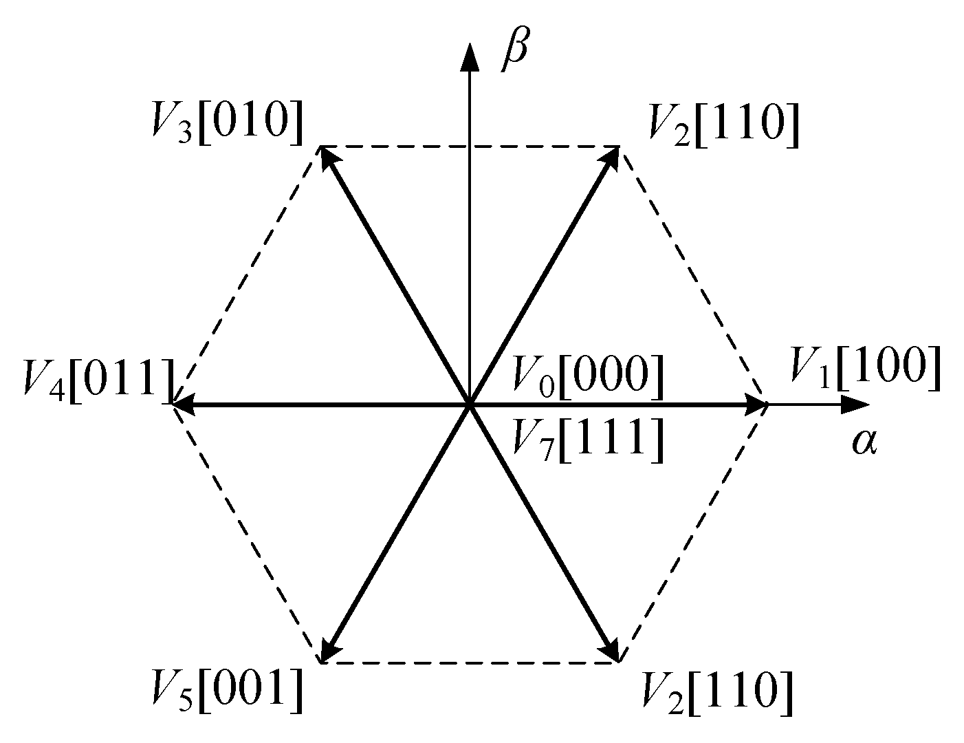
. To prevent short-circuit faults, each phase bridge is configured with two distinct switching states: either the upper bridge turns on while the lower bridge turns off, or vice versa. In general, the grid structure is considered comparable to the ac motor structure because the two systems have similar equivalent configurations with the series resistor, the series inductor, and the ac sinusoidal source. Thus, the grid with the input resistance and inductance is generally termed a virtual ac motor. To introduce ac motor techniques to ac grid systems with the ac-dc converters. Consequently, there are a total of 2 3 = 8 switching states corresponding to seven rectifier voltage vectors, as depicted in Figure 2. The switching functions S x   ( x = a , b , c ) represent the switching states of each bridge arm as follows:
S x = 1 ,   S x 1   ON ,   S x 2   OFF 0 ,   S x 1   OFF ,   S x 2   ON   x = a , b , c  
The mathematical equation of the converter in α β frame is
e α β = R i α β + L d i α β d t + v r e c α β
where e α β is the source voltage vector, i α β is the current vector, and v r e c α β is the rectifier voltage vector.
After discretizing, Equation (2) can be
L T s p i α β k + 1 i α β ( k ) = e α β k R i α β k v r e c α β k  
Simplify (3), the predicted grid current at k + 1 th instant is expressed as follows:
i α β k + 1 = 1 R T s p L i α β k + T s p L e α β k T s p L v r e c α β k
For the concept of virtual flux, the grid is considered as a fictitious AC motor, where the input L and R is the stator leakage inductance and resistance. Here, the virtual flux vector ψ can be computed as the integral of the grid voltage e as
ψ α β = e α β d t
According to (2) and (5), the virtual flux vector is expressed by
ψ α β = R i α β + v r e c α β d t + L i α β  
In the α β stationary frame, as the grid voltage and current vectors are employed to represent the complex power, the active and reactive power can be calculated by employing the virtual flux and grid current. Given a balanced three-phase power supply and a constant amplitude of the virtual flux vector of grid voltage, P and Q can be expressed as
P = ω ψ α i β ψ β i α Q = ω ψ α i α + ψ β i β  
where ω is the grid angular frequency.

3. Proposed MPVFDPC with Switching State Predetermination Approach

In order to attain minimal switching loss performance and sinusoidal grid current of the PWM rectifier under both ideal and distorted grid voltage states, a modified MPVFPDC with switching state predetermination approach is proposed. By exploiting the DPWM concept, the traditional switching state evaluation process is replaced by a switching state predetermination strategy. This strategy performs an online predetermination of four switching states to evaluate in the next sampling instant instead of using all switching states as in conventional MPC approaches. Additionally, the predetermination of switching states achieves low switching loss performance by generating clamping regions corresponding to the leg that transmits the largest absolute current value. According to this, a switching state predetermination is integrated into the MPVFDPC scheme. Meanwhile, to preserve sinusoidal grid current waveforms even with grid voltage distortion, virtual flux control is used in the MPVFDPC strategy. The next sections will theoretically explain the modified MPVFPDC with a switching state predetermination approach.

3.1. Construction of Virtual Flux Estimation

Typically, a simple integrator is employed to perform the integral operation in (5), and its transfer function is expressed as:
G s = 1 s  
Employing a pure integrator to compute the grid virtual flux vector can give rise to two primary problems. First, the presence of a DC offset may result in integration drift. Second, the output signal may experience the generation of DC bias because of unknown initial terms of the input voltages or currents. To tackle this issue, a first-order low-pass filter and a compensation gain C = 1 j ω / 2 π f , adopted from [8], will be employed. Figure 3 illustrates the realization of integral operation in this study.
From (4) and applying the realization of integral operation in Figure 3, the virtual flux vector can be estimated by employing measured grid current and rectifier voltage.

3.2. Construction of Switching State Predetermination Strategy

The switching loss of power switches in every switching instant is defined by the magnitude of the conducted current. Therefore, minimal switching loss can be attained by avoiding the alternating switching state of the phase that transmits the largest absolute current value. In the conventional MPC approach, all eight switching conditions are tested at each sampling instant to select the optimal one that results in the smallest error between the control variables and the corresponding reference. However, in the proposed method, only four switching states are evaluated every sampling instant to achieve both minimum switching loss and sinusoidal grid current waveforms. As mentioned earlier, by exploiting the DPWM concept, the four switching states are predetermined to prohibit the switching of the phase leg that flows the largest current in the next sampling instant. In order to correctly predetermine four switching states that stop the switching operation of the phase leg while maintaining sinusoidal grid currents, clamping regions need to be determined based on the employment of rectifier voltages and grid currents. In this study, reference rectifier voltages and reference grid currents will be employed to avoid a delay of one sampling period and inaccuracy in determining the clamping regions because of ripples in actual grid currents. The reference grid currents can be obtained as follows:
i α β * k + 1 = e α β ( k + 1 ) V p e a k 2 × P * k + 1 + Q * k + 1 e β α ( k + 1 ) e α β ( k + 1 )  
where V p e a k is the peak value of the grid voltage. The reference grid currents at ( k + 1 ) th instant can be yielded by one-step forward i α β * k + 1 . The reference rectifier voltage can be given by combining (4) and (9) as follows:
v r e c α β * k + 1 = e α β k + 1 + L T s p 1 R T s p L i l α β * k + 1 i l α β * ( k + 2 )  
The clamping regions will be determined using the magnitude of the reference rectifier voltage calculated by (10) and the absolute magnitude of the corresponding reference grid currents. To implement this, the reference rectifier voltages in (10) are transformed into a b c stationary frame components. Then, the three-reference rectifier voltages will be listed based on their magnitudes and called v r e c m a x * , v r e c m i d * , and v r e c m i n * . When a reference rectifier voltage is assigned as v r e c m i d * , the corresponding phase leg should not be clamped to ensure that the PWM rectifier works in the linear modulation ranges. Therefore, two-phase legs corresponding to the maximum and minimum values of the reference rectifier voltage might be clamped to stop switching operation every fundamental period. Between these phase legs corresponding to v r e c m a x * and v r e c m i n * , the one that conducts a larger absolute grid current will be selected for clamping. When the phase leg corresponding to v r e c m a x * is selected for clamping, the upper clamping regions will be determined by predetermining four switching states in such a manner that the upper switches in this phase leg are maintained at ON-state. Meanwhile, the lower clamping regions will be determined when the phase leg corresponding to v r e c m i n * is selected for clamping. Four switching states will be predetermined to keep the lower switches in this phase leg turning ON. In every fundamental period, each phase leg can be clamped to the upper rail and lower rail corresponding to the region where the related reference rectifier voltage is assigned as v r e c m a x * and v r e c m i n * , respectively. These clamping regions are determined by reference rectifier voltages and grid currents, and four switching states are predetermined to be evaluated in the next sampling instant during clamping regions. Thanks to the predetermined switching states, the switch in the phase leg that transmits the largest absolute current value is stopped from switching, leading to a reduction in switching loss and an increase in the efficiency of the PWM rectifier. Table 1 presents the clamping phase corresponding to reference rectifier voltages and grid currents and the predetermined switching conditions in each case.

3.3. Construction of MPVFDPC with Switching State Predetermination

The overall architecture of the proposed MPVFDPC with switching state predetermination is depicted in Figure 4. The three-phase input currents and voltages are measured with current and voltage sensors. The currents and voltages are transformed from the abc frame to the αβ frame to convert three quantities with a 120° phase shift with respect to each other to two quantities with a 90° phase shift with respect to each other, which can simplify calculations related to controller design. The current and voltage signals in the αβ frame are discretized from continuous domain to discrete domain. In addition, the predictive virtual flux in the next instant, which is used to predict the future power elements, is obtained based on the source voltage in the αβ frame. On the other hand, the reference of the real power reference can be achieved by the regulation of the PI controller for the dc-link voltage of the converter. The unity power operation is guaranteed by setting the reactive power reference to zero. Those power element references are used to determine the rectifier voltage reference using the relationship between voltage and power components. Next, according to the rectifier voltage reference along with the input current signals, the switching states that will be used for high efficiency can be predetermined at every step, as shown in Table 1. Only the predetermined switching states are employed for the next-step operation, which guarantees low switching losses and highly efficient converter operation. The predictive active and reactive power are determined using (7) in the following manner:
P k + 1 = ω ( ψ α k + 1 i β k + 1 ψ β k + 1 i α k + 1 ) Q k + 1 = ω ( ψ α k + 1 i α k + 1 + ψ β k + 1 i β k + 1 )  
Every sampling instant, four predictive active P and reactive power Q values corresponding to four predetermined switching states acquired by the switching state predetermination block are generated. To choose the optimal switching states among four predetermined switching states and realize the VFDPC scheme, the cost function for power control is formulated as follows:
g = P * k + 1 P ( k + 1 ) + Q * k + 1 Q k + 1
By combining the switching state predetermination strategy and MPVFDPC scheme, the proposed approach can achieve low switching loss performance and sinusoidal grid current of the PWM converter with distorted as well as ideal source voltage. It reveals that the developed approach does not need any additional hardware.

4. Results and Discussion

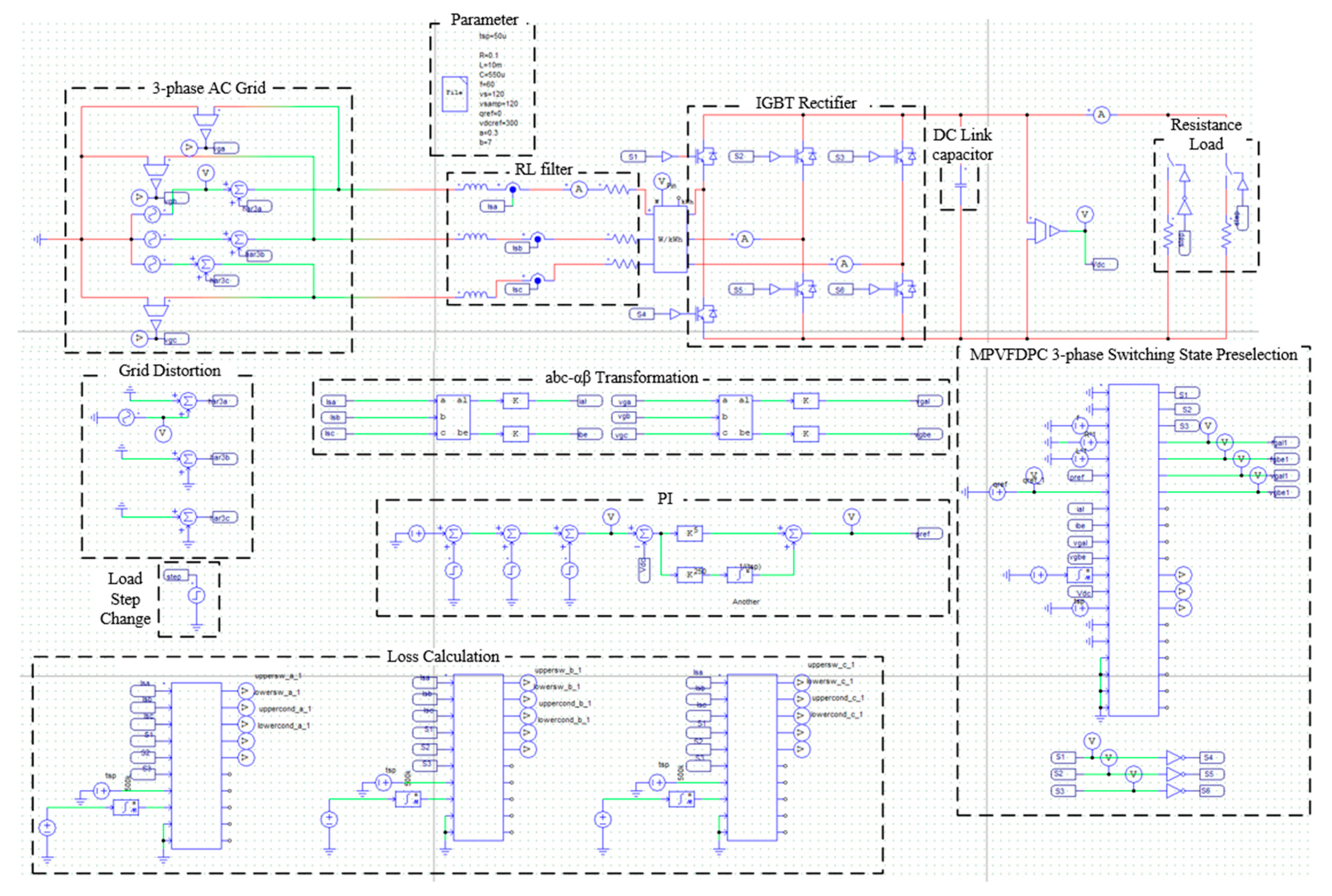
Simulation and experimentation are achieved to verify the developed scheme’s dynamic as well as steady-state performance. The distorted grid voltage state is generated by injecting seventh-order harmonic components into one phase of the grid voltage, and then the operation of the PWM rectifier is investigated as well. Additionally, the developed MPVFDPC is compared to Conv. MPDPC [9] and Conv. MPVFDPC, which is employed by applying the same virtual flux estimation as in the proposed approach. In the simulation, the circuit simulator, PSIM, was used. The schematic of the PWM rectifier model and the function of each block are specified in Figure 5. The main parameters for the simulation and experiment are illustrated in Table 2.
The steady-state results of Conv. MPDPC, Conv. MPVFDPC, and proposed MPVFDPC under an ideal grid voltage state are depicted in Figure 6a, 6b, and 6c, respectively. Here, the reference DC bus voltage V d c , r e f = 300   V is set, leading to the resulting reference active power P * = 900   W , whereas the reference reactive power Q * is zero to obtain unity power factor. In channel (i) of Figure 6, the grid currents obtained by three approaches are sinusoidal and balanced. It is shown that the a-phase source voltage and current are in phase and possess the unity power factor characteristics as expected. In terms of switching patterns, the switching patterns derived by the proposed MPVFDPC approach comprise clamping regions corresponding to one-third of the fundamental period. The non-switching regions are placed correctly in the vicinity of the maximum grid currents, as expected. In channel (ii) of Figure 6, the DC bus voltage, active power, and reactive power follow the corresponding references accurately in both three control schemes with negligible ripples.
Figure 7 shows the steady-state simulation waveforms of the PWM rectifier under the distorted grid voltage state obtained by three control schemes. The 10% seventh-order harmonic component is imposed on the a-phase grid voltage. Then, as depicted in Figure 7a, the grid currents produced by the Conv. MPDPC are distorted. Meanwhile, the grid currents acquired by Conv. MPVFDPC and proposed MPVFDPC are kept in sinusoidal form due to the implementation of virtual flux control. As observed in the presence of distorted grid voltage, the unity power factor operation is sustained. Furthermore, the patterns of the switch operation derived by the developed MPVFDPC approach comprise non-switching regions corresponding to one-third of the fundamental period, as shown in Figure 7c. These non-switching periods occur in the vicinity of the maximum of grid currents, even with grid voltage distortion. In channel (ii) of Figure 7, the DC bus voltage, active power, and reactive power follow accurately the corresponding references, but the DC bus voltage produced by the Conv. MPDPC has a slightly higher ripple than the two remaining approaches.
The dynamic performance validation is carried out by periodically altering the reference value of the DC bus voltage between 250 V and 300 V. Figure 8 indicates that the grid currents, DC bus voltage, and active power can promptly follow the command without experiencing overshooting. Moreover, the unity power factor is consistently sustained throughout the dynamic response. The dynamics of the developed MPVFDPC method are similar to those of the two conventional approaches. Additionally, the proposed approach properly creates clamping regions under the alteration in the reference DC bus voltage.
In order to further prove the proposed scheme, the PWM rectifier experiment setup is depicted in Figure 9. The testing devices and experiment parameters are listed in Table 3.
The sampling frequency of the proposed model predictive control algorithm for the ac-dc converter was 20 kHz. The actual switching frequency was about 8 kHz, which varies because the model predictive control platform leads to varying switching frequency operations. In addition, the voltage and current sensors used in this experiment were LV25-P and LA55-P, respectively, as shown in Table 3. The experimental waveforms of the PWM rectifier in steady-state operation with different approaches are presented in Figure 10. Similar to the simulation, the reference DC bus voltage V d c , r e f = 300   V results in P * = 900   W and Q * is zero for the unity power factor. As can be seen in channel (i) of Figure 10, the grid currents synthesized from three approaches are sinusoidal and balanced. It is observed that the a-phase grid voltage and current are in phase and operate with the unity power factor as expected. In terms of switching patterns, the switching patterns derived by the proposed MPVFDPC approach comprise clamping regions corresponding to one-third of the Figure 7c period. These clamping regions are placed correctly in the vicinity of the maximum grid currents, as in the simulation. Additionally, the DC bus voltage, active power, and reactive power correctly reach the reference value with negligible ripple.
Under the distorted grid voltage state, the 10% seventh-order harmonic component is imposed on the a-phase grid voltage, as depicted in Figure 11. The grid current acquired by the Conv. MPDPC is highly distorted. In contrast, the grid currents with Conv. MPVFDPC and proposed MPVFDPC are better, where the sinusoidal form is maintained due to the implementation of virtual flux control. As observed in the presence of distorted grid voltage, the unity power factor operation is sustained. Furthermore, in Figure 11c, the switching patterns acquired by the developed MPVFDPC approach comprise non-switching regions equal to one-third of the fundamental period.
In order to verify the dynamic experimental performance of the developed approach, the active power reference is increased from 600 W to 900 W in Figure 12. It is evident that the waveform of a-phase grid current acquired by three control schemes can quickly track the change in reference active power without overshooting. In channel (ii) of Figure 12, it shows that active and reactive powers respond fast to the change of reference. The dynamics of the developed MPVFDPC method are comparable to conventional approaches. Furthermore, the developed MPVFDPC approach correctly generates clamping regions even during dynamic performance, as can be seen from the a-phase switching pattern.
From the steady-state and dynamic performance results in both simulation and experiment, the accurate operation of the proposed MPVFDPC with switching state predetermination approach is demonstrated. The grid current is guaranteed under distorted as well as ideal grid conditions, whereas the same dynamic performance is achieved. A quantitative comparison of the average THD of grid currents, total switching loss, error between actual and reference active power, and error between actual and reference reactive power for three control schemes is illustrated in Figure 13 and Figure 14. Regarding the switches’ losses in the PWM converter, the switching and conduction losses are estimated in accordance with the application note in [21] using the datasheet parameters of IGBT module SKM50GB123D [22]. Although this paper targets the same power circuit and the same purpose for high efficiency as well as immunity from grid voltage distortion, same as the previous paper [19], the main difference of the two papers is the control objective and the corresponding controller design methodology. The control target of this paper is to directly control the real and reactive power components by reducing switching losses. As a result, this paper aims to operate the three-phase ac-dc rectifier by directly calculating the future power elements. In addition, the controller in this paper was designed to make the actual power components directly follow their references, minimizing future power control costs. On the other hand, the paper [19] is based on a controller design with a converter virtual flux as a control objective. Thus, the previous paper was developed in such a way to obtain an optimal converter flux in the future to achieve the desired dc output voltage and sinusoidal input current with a unity power factor.
In Figure 13, the quantitative performance of Conv. MPDPC, Conv. MPVFDPC, and proposed MPVFDPC are presented under variation of sampling period. The selection of the sampling period is important for the converter operation and switching frequency in the MPC technique. Opting for a smaller sampling period enhances system performance, albeit at the cost of higher switching frequencies in power switches. Conversely, a longer sampling period diminishes the system’s performance. It can be clearly shown that the average THD of grid current from the three control schemes is similar. Meanwhile, the total switching loss of the PWM rectifier reduces with the increased sampling period. In Figure 13b, at a low sampling period, the total switching loss acquired by the developed MPVFDPC is reduced compared with two previous schemes by approximately 18%. This difference is lowered when the sampling period increases. Regarding the error between active power (reactive power) and the corresponding reference, the Conv. MPDPC has a slightly higher error than that of the Conv. MPVFDPC and the proposed MPVFDPC.
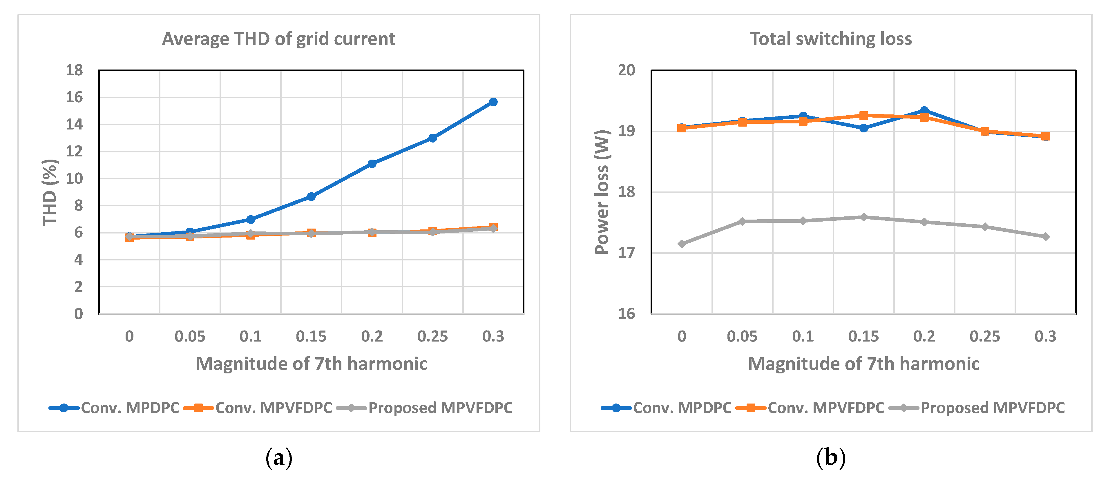
Figure 14a–d show a quantitative comparison between three control schemes following the rise of the added seventh-order harmonics. In Figure 14a, the average THD obtained by Conv. MPDPC significantly increases following the rise of the magnitude of the seventh-order harmonic component. At 30% injection of the seventh-order harmonic component, the average THD increases by about 2.8 times compared to the ideal state. Meanwhile, because of the implementation of virtual flux control, the average THD obtained by Conv. MPVFDPC and proposed MPVFDPC approaches slightly increase when the magnitude of the seventh-order harmonic component rises. Regarding total switching loss, it is clearly observed in Figure 14b that the total switching loss from the developed MPVFDPC is decreased in comparison with the two remaining approaches under different magnitudes of the injected seventh-order harmonic component. This difference is about 10%. Meanwhile, both the error between active power and reference active power and the error between reactive power and reference reactive power obtained by Conv. MPDPC are higher than those of the proposed MPVFDPC approach.
The part focusing on quantitative performance comparison substantiates the effectiveness of the MPVFDPC approach with the switching state predetermination approach under varied conditions. The proposed MPVFDPC method substantially reduces switching losses, enhances the efficiency of the PWM rectifier, and simultaneously upholds the THD performance of grid currents. Moreover, the reduction in switching losses is consistently maintained even as the harmonic component increases, which confirms the robust performance of the proposed MPVFDPC technique. Actual grids often have distorted voltage waveforms in the shape of sinuses with slightly cut-off peaks. Those distorted grid voltage waveforms in the time-domain lead to increased unwanted high-frequency components contained in the frequency components of the grid voltage in the frequency domain. The increased high-frequency elements in the grid voltage can lead to distorted input current waveforms and reduced power controllability. However, the developed method in this paper directly controls real and reactive power components using the virtual flux, which is an integrator of the grid voltage. Integrating the grid voltage in the time domain can function as low-pass filtering of the voltage in the frequency domain, and correspondingly, the adverse effects of distorted grid voltage waveforms with a sinus shape with slightly cut-off peaks on the converter controller can be reduced.

5. Conclusions

A direct power control method on a platform of predictive virtual flux control was proposed to realize highly efficient three-phase ac-dc rectifiers by excluding switching states with high losses in the next step in this article. The proposed technique directly controls the real and reactive power components in the converter to effectively and quickly adjust bi-directional power flow through the converter as well as provide immunity against grid voltage distortion to maintain the quality of the sinusoidal input current. It is shown that the proposed approach can effectively reduce the switching loss of the rectifier by up to 18% by only using future switching states with low switching losses for the direct power control algorithm. In addition, regardless of the exclusion of some switching states, the total harmonic distortion as well as the errors of the real and reactive power components obtained by the proposed method under grid voltage with no distortion are almost the same as the conventional technique, which uses all possible switching states. Moreover, it has been shown that under the conditions of distorted grid voltage, the developed technique leads to much less total harmonic distortion than the conventional method.

Author Contributions

Conceptualization, S.K.; methodology, S.K.; software, M.H.N.; validation, M.H.N.; formal analysis, M.H.N.; investigation, M.H.N.; resources, S.K.; data curation, M.H.N.; writing—original draft preparation, M.H.N.; writing—review and editing, S.K. and S.C.; visualization, M.H.N.; supervision, S.K.; project administration, S.K.; funding acquisition, S.K. All authors have read and agreed to the published version of the manuscript.

Funding

This work was supported by the National Research Foundation of Korea (NRF) Grant funded by the Korea Government, Ministry of Science and ICT (MSIT) under Grant 2020R1A2C1013413.

Data Availability Statement

Data are contained within the article.

Conflicts of Interest

The authors declare no conflicts of interests.

References

  1. Nordman, B.; Christensen, K. DC Local Power Distribution: Technology, Deployment, and Pathways to Success. IEEE Electrif. Mag. 2016, 4, 29–36. [Google Scholar] [CrossRef]
  2. Sayed, K.; Almutairi, A.; Albagami, N.; Alrumayh, O.; Abo-Khalil, A.G.; Saleeb, H. A Review of DC-AC Converters for Electric Vehicle Applications. Energies 2022, 15, 1241. [Google Scholar] [CrossRef]
  3. Dharmasena, S.; Olowu, T.O.; Sarwat, A.I. Bidirectional AC/DC Converter Topologies: A Review. In Proceedings of the 2019 SoutheastCon, Huntsville, AL, USA, 11–14 April 2019; pp. 1–5. [Google Scholar]
  4. Singh, B.; Singh, B.N.; Chandra, A.; Al-Haddad, K.; Pandey, A.; Kothari, D.P. A review of three-phase improved power quality AC-DC converters. IEEE Trans. Ind. Electron. 2004, 51, 641–660. [Google Scholar] [CrossRef]
  5. Zhi, D.; Xu, L.; Williams, B.W. Improved Direct Power Control of Grid-Connected DC/AC Converters. IEEE Trans. Power Electron. 2009, 24, 1280–1292. [Google Scholar] [CrossRef]
  6. Zheng, L. Research on Two-stage Isolated AC-DC Converter with PSO Optimized PI Control. J. Electr. Eng. Technol. 2024, 19, 1619–1631. [Google Scholar] [CrossRef]
  7. Antoniewicz, P.; Kazmierkowski, M.P. Virtual-Flux-Based Predictive Direct Power Control of AC/DC Converters with Online Inductance Estimation. IEEE Trans. Ind. Electron. 2008, 55, 4381–4390. [Google Scholar] [CrossRef]
  8. Nguyen, M.; Kwak, S.; Choi, S. Model Predictive Based Direct Power Control Method Using Switching State Preference for Independent Phase Loss Decrease of Three-Phase Pulsewidth Modulation (PWM) Rectifiers. IEEE Access 2024, 11, 5864–5881. [Google Scholar] [CrossRef]
  9. Zhangyong, C. Model Predictive Controlled Dual Active Bridge Converter with Efficiency Optimization and Fast Dynamic Response. J. Electr. Eng. Technol. 2024, 19, 521–534. [Google Scholar] [CrossRef]
  10. Rahoui, A.; Bechouche, A.; Seddiki, H.; Abdeslam, D.O. Virtual Flux Estimation for Sensorless Predictive Control of PWM Rectifiers under Unbalanced and Distorted Grid Conditions. IEEE J. Emerg. Sel. Top. Power Electron. 2021, 9, 1923–1937. [Google Scholar] [CrossRef]
  11. Liping, Z. Model Predictive Control based Discontinuous PWM Algorithm for 3L-NPC Inverter. J. Electr. Eng. Technol. 2022, 17, 425–436. [Google Scholar] [CrossRef]
  12. Cho, Y.; Lee, K.B. Virtual-Flux-Based Predictive Direct Power Control of Three-Phase PWM Rectifiers with Fast Dynamic Response. IEEE Trans. Power Electron. 2016, 31, 3348–3359. [Google Scholar] [CrossRef]
  13. Dae-Woong, C.; Sul, S.K. Minimum-loss strategy for three-phase PWM rectifier. IEEE Trans. Ind. Electron. 1999, 46, 517–526. [Google Scholar] [CrossRef]
  14. Asiminoaei, L.; Rodriguez, P.; Blaabjerg, F.; Malinowski, M. Reduction of Switching Losses in Active Power Filters with a New Generalized Discontinuous-PWM Strategy. IEEE Trans. Ind. Electron. 2008, 55, 467–471. [Google Scholar] [CrossRef]
  15. Wang, L.; Han, T.; Zhao, T.; He, J. Model Predictive Control with Secondary Objective Functions for Power Module Loss Reduction. In Proceedings of the 2019 IEEE Energy Conversion Congress and Exposition (ECCE), Baltimore, MD, USA, 29 September–3 October 2019; pp. 225–231. [Google Scholar]
  16. Espinosa, E.; Espinoza, J.; Rohten, J.; Silva, J.; Muñoz, J.; Melín, P. Finite control set model predictive control with reduced switching frequency applied to multi-cell rectifiers. In Proceedings of the 2015 IEEE International Conference on Industrial Technology (ICIT), Seville, Spain, 17–19 March 2015; pp. 2261–2267. [Google Scholar]
  17. Kwak, S.; Park, J.C. Model-Predictive Direct Power Control with Vector Preselection Technique for Highly Efficient Active Rectifiers. IEEE Trans. Ind. Inform. 2015, 11, 44–52. [Google Scholar] [CrossRef]
  18. Shi, H.; Rong, X.; Tuo, P.; Yao, Y.; Gong, Z. Model Predictive Direct Power Control for Virtual-Flux-Based VSR with Optimal Switching Sequence. IEEE Access 2022, 10, 38272–38283. [Google Scholar] [CrossRef]
  19. Nguyen, M.; Kwak, S.; Choi, S. Model Predictive Virtual Flux Control Method for Low Switching Loss Performance in Three-Phase AC/DC Pulse-width-Modulated Converters. Machines 2024, 12, 66. [Google Scholar] [CrossRef]
  20. Zhang, Y.; Peng, Y.; Yang, H. Performance Improvement of Two-Vectors-Based Model Predictive Control of PWM Rectifier. IEEE Trans. Power Electron. 2016, 31, 6016–6030. [Google Scholar] [CrossRef]
  21. Graovac, D.; Pürschel, M. IGBT Power Losses Calculation Using the Data-Sheet Parameters; Infineon: Neubiberg, Germany, 2009. [Google Scholar]
  22. SEMIKRON. “SKM50GB123D” Datasheet; Semikron Dandoss: Essex, UK, 2006. [Google Scholar]
Figure 1. Three-phase rectifier.
Machines 12 00290 g001
Figure 2. PWM rectifier voltage vector and switching state.
Machines 12 00290 g002
Figure 3. Realization of integral operation.
Machines 12 00290 g003
Figure 4. Overall block diagram of proposed MPVFDPC with switching state predetermination.
Machines 12 00290 g004
Figure 5. Schematic of PWM rectifier model in PSIM.
Machines 12 00290 g005
Figure 6. Steady-state waveforms with ideal grid voltage state obtained by (a) Conv. MPDPC; (b) Conv. MPVFDPC, and (c) Proposed MPVFDPC (i) a-phase grid voltage, grid currents, switching patterns; (ii) DC bus voltage, active and reactive power.
Machines 12 00290 g006
Figure 7. Steady-state waveforms with distorted grid voltage state obtained by (a) Conv. MPDPC; (b) Conv. MPVFDPC, and (c) Proposed MPVFDPC (i) a-phase grid voltage, grid currents, switching patterns; (ii) DC bus voltage, active and reactive power.
Machines 12 00290 g007
Figure 8. Dynamic performance simulation waveforms under ideal grid voltage state obtained by (a) Conv. MPDPC; (b) Conv. MPVFDPC, and (c) Proposed MPVFDPC (i) a-phase grid voltage and current, switching patterns; (ii) Zoom-out a-phase grid voltage and current, switching patterns; (iii) DC bus voltage, active and reactive power.
Machines 12 00290 g008
Figure 9. Experimental setup of PWM rectifier.
Machines 12 00290 g009
Figure 10. Steady-state waveforms with ideal grid voltage state acquired by (a) Conv. MPDPC; (b) Conv. MPVFDPC, and (c) Proposed MPVFDPC (i) a-phase grid voltage, grid currents; (ii) switching patterns and DC bus voltage; (iii) active and reactive power.
Machines 12 00290 g010
Figure 11. Steady-state waveforms with distorted grid voltage state obtained by (a) Conv. MPDPC; (b) Conv. MPVFDPC, and (c) Proposed MPVFDPC (i) a-phase grid voltage, grid currents; (ii) switching patterns and DC bus voltage; (iii) active and reactive power.
Machines 12 00290 g011
Figure 12. Dynamic performance waveforms with ideal grid voltage state obtained by (a) Conv. MPDPC; (b) Conv. MPVFDPC, and (c) Proposed MPVFDPC (i) a-phase grid voltage and grid current, a-phase switching pattern; (ii) Active and reactive power.
Machines 12 00290 g012
Figure 13. Performance comparison between Conv. MPDPC, Conv. MPVFDPC, and proposed MPVFDPC under variation of sampling period: (a) Average THD of grid current, (b) Total switching loss, (c) Error between active power and reference active power, (d) Error between reactive power and reference reactive power.
Machines 12 00290 g013
Figure 14. Performance comparison between Conv. MPDPC, Conv. MPVFDPC, and proposed MPVFDPC under variation of injected seventh-order harmonic component: (a) Average THD of grid current, (b) Total switching loss, (c) Error between active power and reference active power, (d) Error between reactive power and reference reactive power.
Machines 12 00290 g014aMachines 12 00290 g014b
Table 1. Predetermined switching conditions following reference converter voltages and grid currents.
Reference Rectifier VoltageGrid CurrentClamping PhasePredetermined Switching States
v r e c m a x * v r e c m i n *
v r e c a * v r e c b * i s a > i s b Phase- a [100], [110], [101], [111]
i s a < i s b Phase- b [000], [100], [001], [101]
v r e c c * i s a > i s c Phase- a [100], [110], [101], [111]
i s a < i s c Phase- c [000], [100], [110], [010]
v r e c b * v r e c a * i s b > i s a Phase- b [110], [010], [011], [111]
i s b < i s a Phase- a [000], [010], [011], [001]
v r e c c * i s b > i s c Phase- b [110], [010], [011], [111]
i s b < i s c Phase- c [000], [100], [110], [010]
v r e c c * v r e c a * i s c > i s a Phase- c [011], [001], [101], [111]
i s c < i s a Phase- a [000], [010], [011], [001]
v r e c b * i s c > i s b Phase- c [011], [001], [101], [111]
i s c < i s b Phase- b [000], [100], [001], [101]
Table 2. Parameter of PWM rectifier system.
ParameterValue
Grid voltage peak value e 120 V
Input resistance R 0.1 Ω
Input inductance L 10 mH
DC bus capacitance C d c 550 µF
Output resistance R L 100 Ω
Fundamental frequency f 60 Hz
Sampling period T s p 50 µs
Reference DC output voltage V d c , r e f 300 V
P gain k p 0.2
I gain k i 5
Table 3. Testing device and experiment parameter of PWM rectifier system.
Component NamePart Number
AC SourceChroma 61702
Current SensorLA55-P
Voltage SensorLV25-P
Digital Signal ProcessorTI TMS320F28335
Gate DriverSKHI22AR
IGBTSKM50GB123D
RL FilterR = 0.1 Ω, L = 10 mH
DC bus capacitance C d c = 550   µ F
Resistance Load R L = 100   Ω
Disclaimer/Publisher’s Note: The statements, opinions and data contained in all publications are solely those of the individual author(s) and contributor(s) and not of MDPI and/or the editor(s). MDPI and/or the editor(s) disclaim responsibility for any injury to people or property resulting from any ideas, methods, instructions or products referred to in the content.

