Article

Failure Inducement Factor Analysis and Optimal Design Method of Ball Bearing Cage for Aviation Motor

1
School of Mechatronics Engineering, Henan University of Science and Technology, Luoyang 471023, China
2
Changzhou NRB Corporation, Changzhou 213000, China
3
Key Laboratory of Power Transmission Technology on Aero Engine, Aero Engine Corporation of China, Shenyang 110015, China
*
Author to whom correspondence should be addressed.
Machines 2024, 12(7), 466; https://doi.org/10.3390/machines12070466
Submission received: 23 June 2024 / Revised: 8 July 2024 / Accepted: 9 July 2024 / Published: 10 July 2024
(This article belongs to the Section Electrical Machines and Drives)

Abstract

:
In experiments of aviation motor bearings, when the deep-groove ball bearings are subjected to an overturning moment at high speed, it often happens that the rivet on the cage breaks and the debris invades the raceway, resulting in bearing failure. To address the problem of early failure of deep-groove ball bearing cages and rivets in aviation motors, the causes of early failure were analyzed from the aspect of cage design in this study. The influence of the raceway and cage structure parameters on the dynamic contact characteristics of the rolling element and cage under the action of overturning torque were analyzed, the weak link of the cage was determined, and the cage design parameters were optimized. The results show that with an increase in the cage width and pocket radius, the impact force between the ball and cage first decreases and then increases, and the tilt angle of the cage gradually decreases. A larger channel radius and smaller clearance can slow down the interaction between the cage and the rolling element and make the cage run more smoothly. Increasing the thickness of the cage can ensure that the rivet part of the cage is at a low stress level, and the risk of premature fatigue failure at the rivet part can be reduced by maintaining a small gap–fit relationship between the rivet and rivet holes. The research results indicate that the working condition adaptability of the bearing cage for aviation motors can be improved, and the design method for this type of bearing can be enhanced.

1. Introduction

An aviation motor is the power source of instruments and other accessory systems in various aircrafts. It ensures the accurate realization of aircraft functions. A deep-groove ball bearing has a small friction coefficient, large radial load, small axial load, and high speed, and is often used as a fixed-end support in the design of aviation motors. Due to the diversity of aircraft tasks, the bearings of an aircraft motor work under complex conditions, such as high-speed rotation accompanied by the rotation of the attachment system and overturning torque. The vibration of a bearing can lead to increased friction between the steel ball and the cage, unstable operation of the cage, and fracture of the cage, which can cause the motor to “lock up” as well as other faults, thus affecting the functional realization of the aircraft. Therefore, considering the failure of the ball bearing cage in aviation motors, the failure-inducing factors must be analyzed from the perspective of the cage structure design by identifying the locked weak link of the cage to improve the reliability of the bearing cage for aviation motors.
During the process of restricting and guiding the movement of the rolling element, the cage exhibits collision and friction behaviors with the rolling element, which has a substantial influence on the dynamic characteristics of the bearings [1]. Gupta [2] established a dynamic model of rolling bearings and studied the influence of the interaction force between the rolling element and the cage on bearing stability. Rivera [3] simplified the bearing dynamic analysis model based on Gupta’s research theory and studied cage stability during bearing operation. Based on the Hertz contact theory, Boesiger et al. [4] studied the impact of the elastic deformation at the contact between the cage and rolling element on the overall running stability of the bearings. Salam et al. [5] conducted a study on the fatigue failure mechanism of an aviation-engine-bearing cage and found that the tilt of the ring during installation caused an impact contact between the steel ball and the cage, thus causing the failure of the cage. Ejaz et al. [6,7] analyzed the causes of failure of aviation motor spindle ball bearings, and their results showed that improper installation, excessive axial load, and intrusion were the main causes of bearing failure. Wei et al. [8] analyzed the failure mechanism of ball bearings in dental air turbines and found that the failure of the cages was mainly caused by overload and poor lubrication. Mishara et al. [9] analyzed the reasons for the raceway failure of the angular contact ball bearing of the double-half inner ring of an aviation engine spindle, and the results showed that overload and unreasonable clearance were the primary causes of bearing failure. Kishore et al. [10] analyzed the failure of double-row spherical roller bearings used in rolling mills and provided corresponding improvement suggestions. Xing et al. [11] analyzed and discussed the fatigue fracture mechanism of the bearing cage of an airhead spindle and hypothesized that the fatigue fracture of the cage mainly depended on the impact force between the steel ball and the cage. Chen et al. [12] analyzed the falling-off fault of the cage of an aviation engine deep-groove ball bearing, and the results showed that the unreasonable mating relationship of the cage rivet caused the cage to separate and fall off. Niu [13] conducted finite element simulations and tests on cages with different clearances to study the influence of the raceway wear degree on the bearing performance under high-speed working conditions. Tu et al. [14] analyzed the magnitude and frequency of the impact force between the rolling element and cage under bearing conditions of acceleration, deceleration, and uniform speed. Liu et al. [15] studied the cause of the fracture of roller-bearing cages under high speeds and obtained the relationship between the cage life and hole fillet size. Pang et al. [16] established a finite element model of a needle roller cage and optimized its pocket and inner diameters. Based on the dynamic analysis method for rolling bearings, Cui et al. [17,18,19] studied the influence of roller imbalance on cage stability and stress distribution. Zhang et al. [20] established a dynamic analysis model of ball bearings under oscillating conditions and studied the effects of the bearing operating parameters, lubricant drag coefficient, and cage pocket clearance on the instantaneous impact behavior between the steel balls and cages and the vibration characteristics of the cages. Jia et al. [21] established a dynamic analysis model of a deep-groove ball bearing crown cage and analyzed the influence of the cage pocket modification radius on the running smoothness and strength of the cage. In summary, extensive research has been conducted on the friction behavior of bearing cages and rolling bodies; however, research on the contact state of rivets in wave cages under vibration conditions is limited. Ujjawal Arya [22] analyzed the influence of three different types of cages on the contact force between the ball and the cage, analyzed the influence of cage radius, cage pocket clearance, cage pocket area and cage inertia on the vortex state of the cage, and deduced that the contact force between the ball and the cage was mainly affected by the cage pocket area and cage radius. Yuan [23] analyzed the changes of the centroid trajectories of cages with different angular contact ball bearing pocket shapes (spherical, square, and cylindrical) with speed and load, and obtained the relationship between the centroid vortex radius of cages and the radius of pocket shapes. The relationship between the slip rate and the inclination angle of each cage and the radial load and speed is obtained by experiments. On the basis of the dynamic wear simulation model of angular contact ball bearings, Chen [24] established dynamic models of ball pocket cages and cylindrical bag cages and studied the influence of cage pocket shape on the dynamic characteristics of angular contact ball bearings with different pocket clearances. It is concluded that the motion stability of differently shaped cages is positively correlated with the distribution stability of the ball.
At present, the knowledge regarding the impact force between the cage and the ball is not sufficient, and the failure and damage of the cage often occur prior to those of the bearing ring and the ball, so it is necessary to study its reasonable size parameters and assembly relationship. In addition, the selection method for the cage pocket opening and rivet sizes is not stipulated in current bearing design guidance manuals, and it is typically designed according to prior experience. However, in practical applications, the structural parameters of the cage and the selection of the rivet matching mode have a significant influence on the fatigue life and operating stability of the bearing cage.
Based on the early abnormal fracture/damage failure case of the bearing cage of an aviation motor, a dynamic analysis model of the motor bearing was established in this study to investigate the influence of the bearing channel and cage’s structural parameters on the impact force between the ball and cage, the tilt angle, and slipping rate of the cage under the action of overturning torque. At the same time, the effect of the fit relation on the internal stress of the rivet is studied to adapt to the working condition of the motor-bearing cage. Furthermore, the design method for the wave cage structure was improved.

2. Dynamic Analysis Model of a Ball Bearing

A dynamic analysis model of a deep-groove ball bearing was established to analyze the weaknesses of the aviation-motor-bearing cage design. As shown in Figure 1, the inertial coordinate system is {OXYZ}, the inner ring coordinate system is { O i x i y i z i } , the steel ball centroid coordinate system is { O b x b y b z b } , the cage center of mass coordinate system is { O c x c y c z c } , and the pocket coordinate system is { O p x p y p z p } .
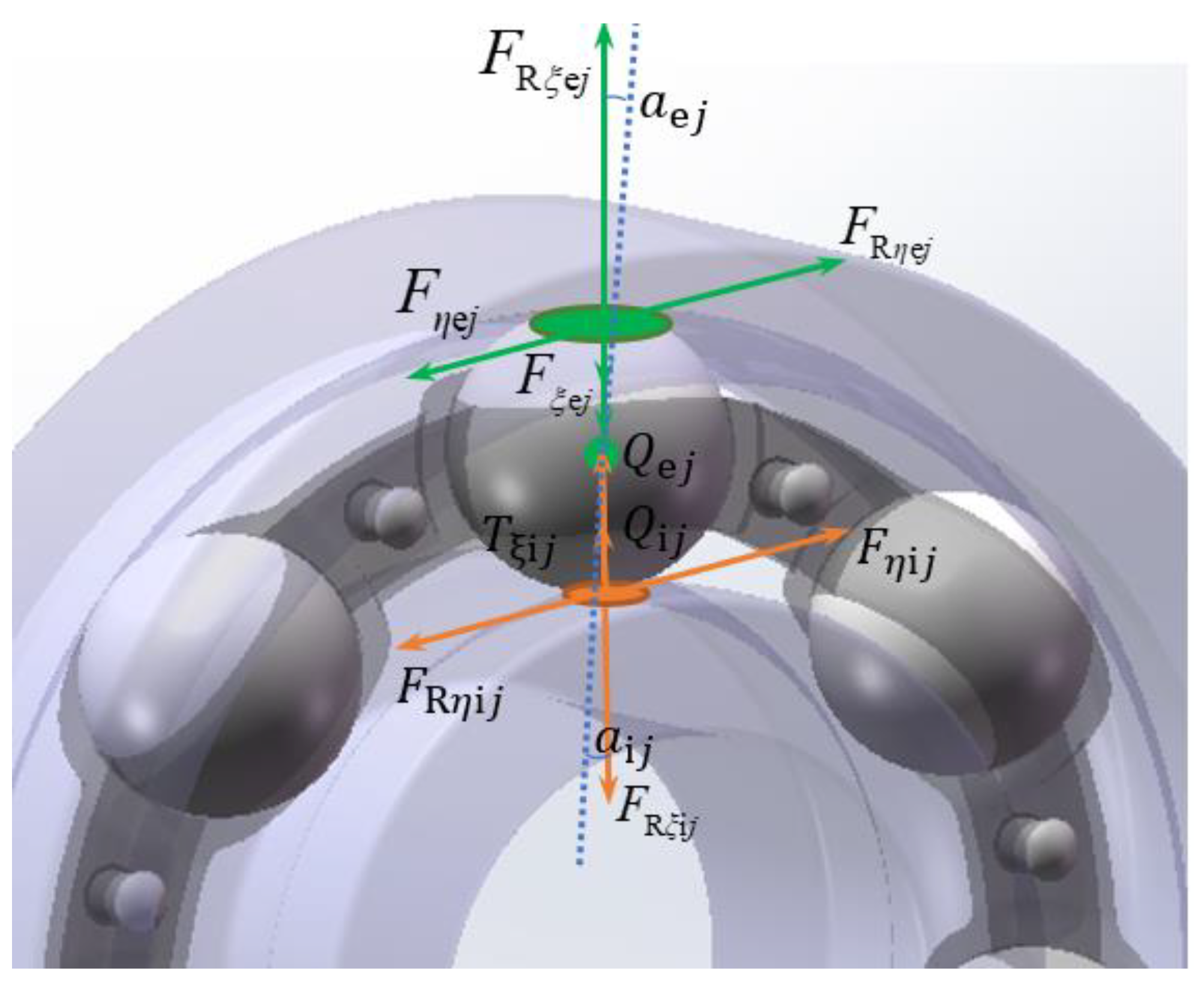
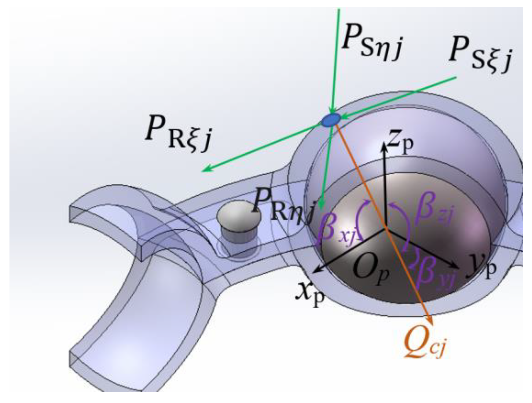
Figure 2 and Figure 3 show the interaction forces between the steel ball, raceway, and cage pocket. The subscripts i and e represent the raceway of the inner and outer ring, respectively. The subscript j denotes the j-th ball; η, ξ, and ρ denote the long axis, short axis, and normal direction of the elliptic contact area, respectively. The contact angle between the inner (outer) ring and j-th ball is a i ( e ) j . Q i ( e ) j is the normal contact force between the j-th ball and the raceway. F R η i j , F R ξ i j , F R η e j , and F R ξ e j are the hydrodynamic frictional forces at the contact inlet zone between a ball and the raceway. T η i ( e ) j and T ξ i ( e ) j are traction forces on the contact surface; their direction is determined by the relative sliding velocity of the contact interface between the steel ball and the channel. Qcj is the impact force between the ball and cage pocket. The angle between Qcj and the Plücker coordinate system { O p x p y p z p } are β x j , β y j , and β z j ; P R η ( ξ ) j is the rolling frictional forces acting on a ball; and P S η ( ξ ) j is the sliding frictional forces acting on a ball.
In the inertial coordinate system, the dynamic differential equations for the j-th ball are established as follows [1]:
A i j T η i j F R η i j + F H η i j T ξ i j + F R ξ i j + F H ξ i j Q i j A e j T η e j F R η i j + F H η i j T ξ e j + F R ξ e j + F H ξ e j Q e j + C p j Q c j x Q c j y Q c j z + P S ξ j + P R ξ j F D j F τ j F η j P S η j P R η j = m b x ¨ b j m b y ¨ b j m b z ¨ b j ,
D W 2 A i j F R ξ i j T ξ i j T η i j + F R η i j 0 D W 2 A e j F R ξ e j T ξ e j T η e j + F R η e j 0 D W 2 P S η j + P R η j 0 P S ξ j + P R ξ j G x j + J x ω ˙ x j G y j + J y ω ˙ y j G z j + J z ω ˙ z j = I b ω ˙ b j x I b ω ˙ b j y I b ω ˙ b j z ,
A i ( e ) j = c o s α i ( e ) j 0 s i n α i ( e ) j 0 1 0 s i n α i ( e ) j 0 c o s α i ( e ) j ,
C p j = 1 0 0 0 c o s φ j s i n φ j 0 s i n φ j c o s φ j ,
Q c j c o s β x j c o s β y j c o s β z j = Q c j x Q c j y Q c j z ,
where A i ( e ) j is the rotation matrix of the j-th ball’s centroid coordinate system and the coordinate system of the inner (outer) ring’s contact surface; F H η i j   a n d   F H η e j are the horizontal components of the hydrodynamic force acting on a ball; C p j is the rotation matrix of the cage’s coordinate system and inner ring’s coordinate system; φ j is the azimuth angle of the balls; F D j is the aerodynamic resistance acting on a ball by gas–oil mixture; F η j   a n d   F τ j are the inertia force components of a ball; m b is the mass of the ball; x ¨ b j ,   y ¨ b j ,   a n d   z ¨ b j are the acceleration components of the ball’s mass center; D w is the ball’s diameter; J x , J y ,   a n d   J z are component moments of the inertia of a ball; ω ˙ x j ,   ω ˙ y j ,   a n d   ω ˙ z j are the angular acceleration components of the balls; G x j , G y j ,   a n d   G z j are the moments of inertia of the steel ball; I b is the moment of inertia of the steel ball in the inertial coordinate system; and ω ˙ b x j ,   ω ˙ b y j ,   a n d   ω ˙ b z j are the angular accelerations of the steel ball in three directions in the inertial coordinate system [1].
In the inertial coordinate system, the dynamic differential equations of the inner ring are expressed as
F x F y F z + j = 1 N B i j T η i j F R η i j T ξ i j + F R ξ i j Q i j = m i x ¨ i y ¨ i z ¨ i ,  
M x M y M z + j = 1 N r i j B i j Q i j 0 T ξ i j F R ξ i j + j = 1 N D W 2 f i · B i j T η i j + F R η i j 0 0 = J i x ω ˙ i x J i y ω ˙ i y J i z ω ˙ i z ,
B i j = c o s α i j 0 s i n α i j s i n α i j s i n φ j c o s φ j c o s α i j s i n φ j s i n α i j c o s φ j s i n φ j c o s α i j c o s φ j ,
ω m = 1 2 ω i ( 1 γ ) ω e ( 1 + γ ) ,
S c = ω m ω c ¯ ω m × 100 % ,
where F x F y F z T and M x M y M z T are the components of the external loads and moments acting on the inner ring, respectively, and B i j is the rotation matrix of the coordinate system of the contact surface between the ball and inner raceway. r i j = d m / 2 D W f i c o s α i j / 2 , where d m is the pitch diameter of the ball during operation, f i ( e ) is the curvature radius coefficient of the inner (outer) raceway, and m i is the inner ring’s mass. x ¨ i ,   y ¨ i ,   a n d   z ¨ i are the acceleration components of the inner ring; ω ˙ i x ,   ω ˙ i y ,   a n d   ω ˙ i z are the angular acceleration components of the inner ring; and ω m is angular velocity component of the cage. For the inclination angle of the cage, ψ c = arctan ( ω c z / ω c x ) , ω e ( i ) is the bearing’s outer (inner) ring speed; γ = D w / d m , d m is the diameter of the bearing; and d m = D e + D i / 2 , where D e ( i ) is the bearing’s outer (inner) diameter. The ± symbol represents a ‘−’ when the inner and outer rings turn opposite to each other, and the symbol is ‘+’ when the inner and outer rings turn in the same direction. S c is the slipping rate of the cage, and ω c ¯ indicates the actual speed of the cage.
The nonlinear dynamic differential equations of the cage in the inertia coordinate system {OXYZ} are written as follows:
j = 1 N C p j Q c j 0 P S ξ j + P R ξ j + C c P S ξ j + P R ξ j P S η j + P R η j 0 = m c x ¨ c m c y ¨ c m c z ¨ c ,
j = 1 N d m 2 · C c Q c j 0 P S ξ j + P R ξ j + D W 2 P S η j + P R η j 0 0 = J c x ω ˙ c x J c y ω ˙ c y J c z ω ˙ c z ,
C c = 1 0 0 0 c o s φ c s i n φ c 0 s i n φ c c o s φ c ,
where N is the number of balls, C c is the rotation matrix of the cage’s centroid coordinate system and the inertial coordinate system, φ c is the azimuth angle of the cage, x ¨ c ,   y ¨ c ,   a n d   z ¨ c are the acceleration components of the inner ring; m c is the cage’s mass; J c x ,   J c y ,   a n d   J c z are component moments of the inner ring inertia; and ω ˙ c x ,   ω ˙ c y ,   a n d   ω ˙ c z are the angular acceleration components of the cage.
Under the impact force Q c j between the steel ball and pocket hole, the rivet rod primarily bears the shear load, and the rivet head bears the tensile and compressive loads. The vulnerable cross-section of the rivet and the failure-prone part are shown in red in Figure 4a. The stress–strain values in the vulnerable area were calculated using the modified Norbert method.
K t = ( K σ K ε ) 1 / 2 ,
K σ = Δ σ / Δ S ,
K ε = Δ ε / Δ e ,
Δ σ · Δ ε = K t 2 · Δ S 2 E ,
K f = K t 1 Δ S / σ u l t ,
Δ σ · Δ ε = K f 2 · Δ S 2 E ,
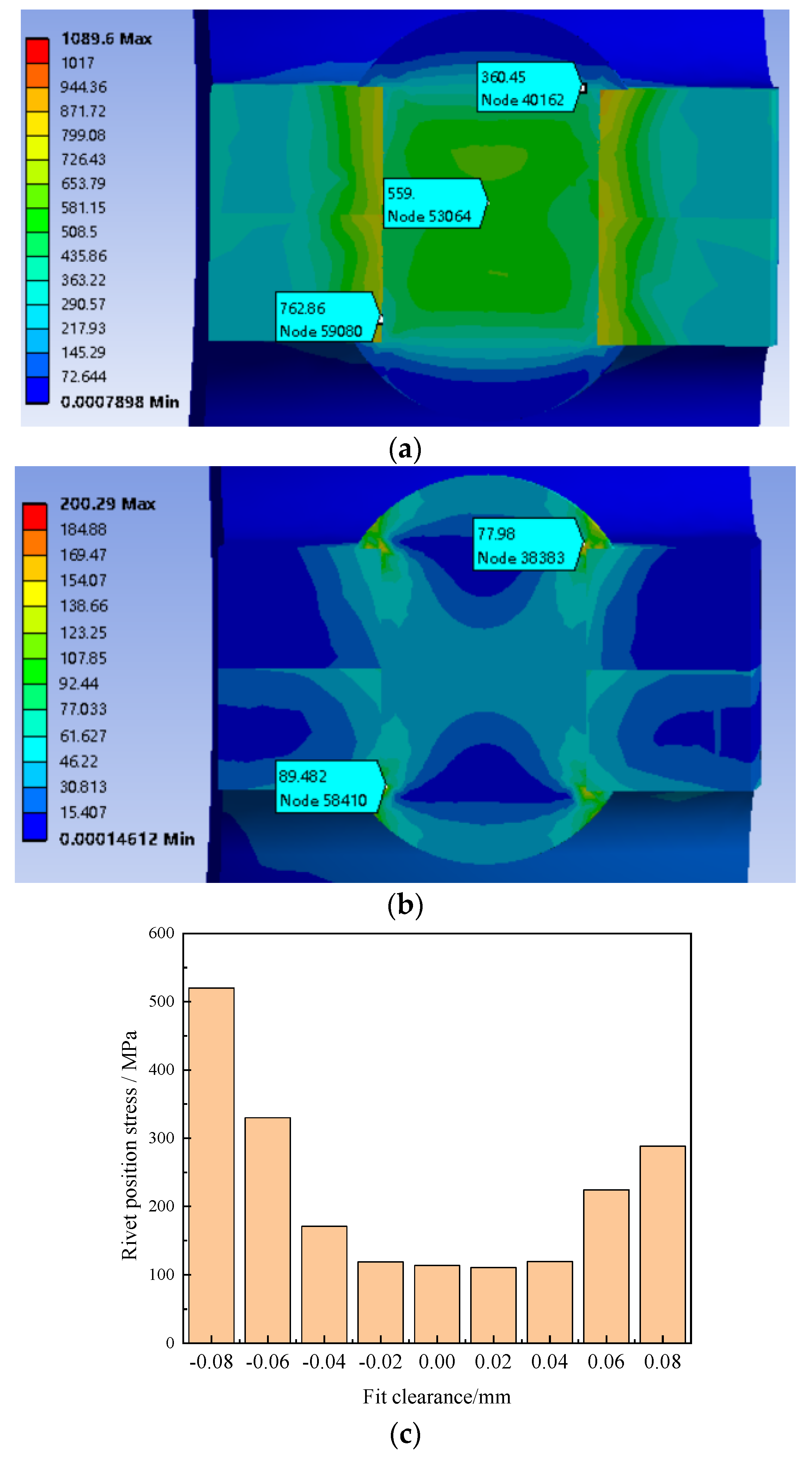
where K t is the theoretical stress concentration coefficient, K σ is the real stress concentration coefficient, K f is the fatigue strength reduction coefficient, Δ σ is the real stress, Δ S is the nominal stress, Δ ε is the real strain, Δ e is the nominal strain, and σ u l t is the ultimate strength. The calculation results of the modified Norbert method are shown in Figure 4a, and the calculation results of the finite element verification are shown in Figure 4b. By comparing the stress concentration locations, the finite element analysis results were found to be more accurate.

3. Results and Analysis

Table 1 lists the main structural parameters and corresponding working conditions of the improved ball bearing based on type 6203 for a specific type of aviation motor. The movement of the cage is guided by the ball. When the bearing operates, the outer ring is fixed and the inner ring is rotated; the lubrication type is grease. The bearing material parameters are shown in Table 2.

3.1. Influence of Cage Structure Parameters on Dynamic Contact Characteristics of Ball and Cage

3.1.1. Influence of Pocket Radius on Dynamic Contact Characteristics of Ball and Cage

The radius of the pocket directly affects the Q c j value between the ball and cage. Figure 5 shows the relationship between the pocket radius and the contact characteristics between the ball and cage. As shown in Figure 5a, within the design range permitted by the pocket radius, the force between the cage and ball first decreases and then increases with an increase in the pocket radius. The impact force is minimized when the pocket radius is 3.46 mm. As shown in Figure 4b, the maximum stress on the rivet occurs at the root of the rivet head, and the position of the maximum stress point does not change with changes in the impact force. In Figure 5b, the variation trend of the rivet position stress with respect to the pocket radius is the same as that of Q c j . In Figure 5c, as the pocket radius increases, the slipping rate of the cage increases. Because the overall value is small, the change in the hole radius had no obvious influence on the stability of the cage within the interval. As the radius increases, the ball has a larger inclination margin when bearing the overturning moment, and the tilt angle of the cage decreases as the pocket radius increases. As shown in Figure 5d, when the radius of pocket is 3.46 mm, the impact force between the ball and cage is at the lowest value, and the contact degree of the cage centroid trajectory is at the optimal level compared with other sizes, indicating that the adjustment of the pocket radius has a certain impact on the stability of the cage.

3.1.2. Influence of Cage Width on Dynamic Contact Characteristics between Ball and Cage

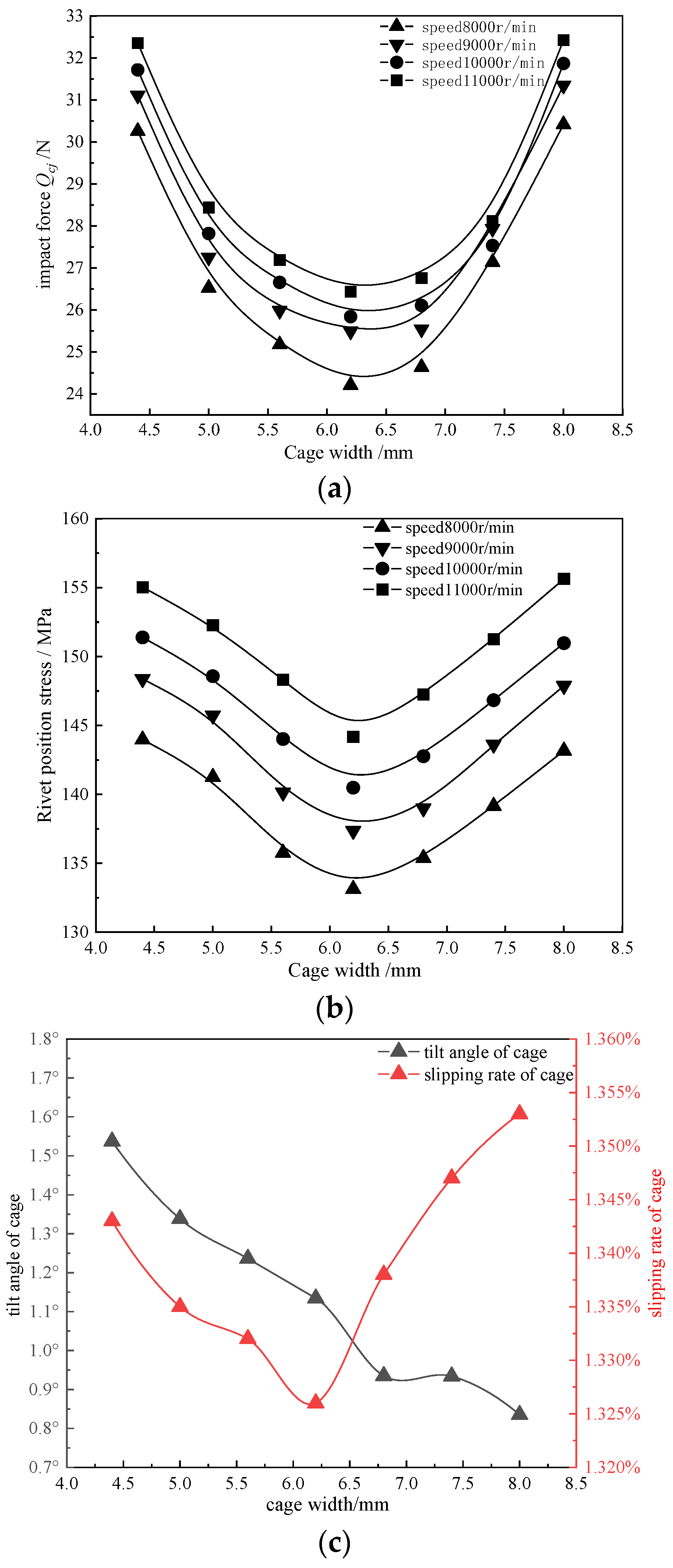
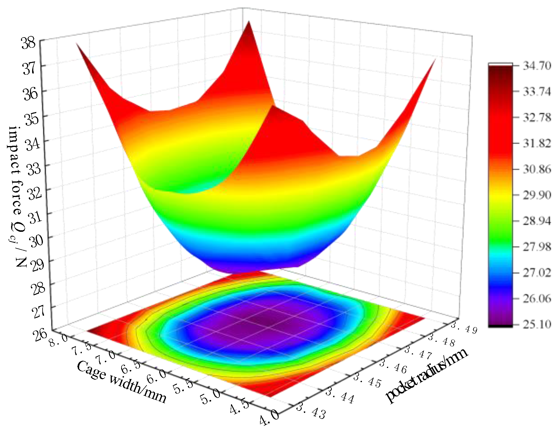
The cage width directly affects the lubrication performance of the steel ball; if the width of the cage is small, the steel ball has more area to leak out and come in contact with the grease, which also affects the strength of the cage. However, the selection of this value is not clearly stipulated in the existing bearing design guidance manuals. The analysis in Figure 6 indicates that a cage width in the middle of the value range can cause the maximum stress and impact force on the rivet to reach the lowest value. By comparing Figure 6a–c, it can be observed that changes in the cage width and pocket radius have the same influence on the contact characteristics between the ball and cage. When the cage width is in the range of 6–6.5 mm, the cage slip rate reaches its lowest value, and the cage tilt angle decreases gradually with an increase in the width.

3.1.3. Influence of Cage Thickness on Contact Characteristics of Steel Ball and Pocket Hole

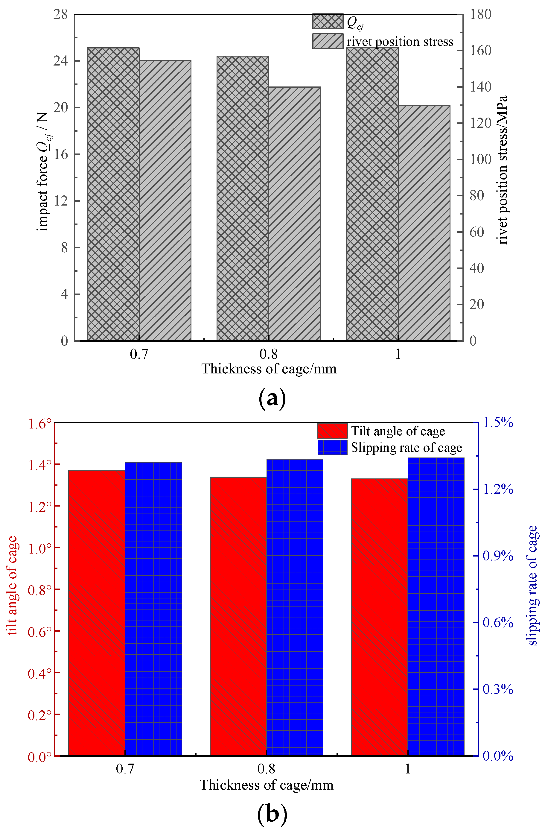
Figure 7 shows the relationship between the cage thickness and the contact characteristics between the ball and cage. The pocket radius with the minimum contact load between the ball and the cage is 3.46 mm at the input boundary. The impact force between the steel ball and cage and the change in the maximum stress at the rivet were analyzed by changing the cage thickness. The initial cage thicknesses were 0.7, 0.8, and 1 mm. Within the variation range of the cage thickness shown in Figure 7a, the impact force between the ball and cage was smallest when the thickness was 0.8 mm. Although the impact force of the cage increased when the thickness was 1.0 mm, the maximum stress at the rivet position decreased with an increase in thickness. Although the thickness of the cage increased, the cage mass increased, the impact force between the ball and cage increased marginally, and the stress at the rivet position decreased owing to the overall strength of the cage. As shown in Figure 7b, an increase in the thickness within the value range does not cause the slipping rate to change significantly, and the stability of the cage is improved.
In order to show the influence of the pocket radius and cage width on the impact force of balls at the same time, and to obtain the influence degree, the full orthogonal decomposition method was adopted to reflect the results more intuitively through multiple points. The effects of the cage width, pocket radius, cage thickness, and other parameters on the cage stress were analyzed. Based on this, the cage size was optimized and improved through the orthogonal experimental method (Table 3) to obtain the most appropriate structural parameters of the cage and minimize the impact force between the rolling element and the cage. As shown in Figure 8, within the designated range the impact force is optimized when the pocket radius and cage width are 3.46 mm and 6 mm, respectively; thus, the cage has the lowest failure risk.

3.2. Influence of Channel Structure Parameters on Contact Characteristics between Ball and Cage

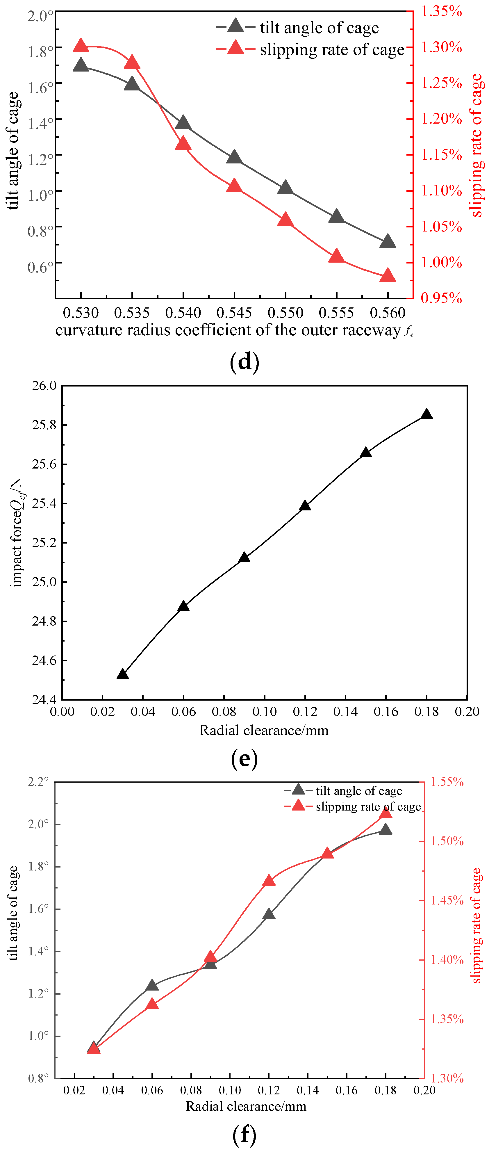
The curvature radius coefficient of the raceway often affects the friction inside the bearing and the contact position of the rolling element. The influence of the change in the of curvature radius coefficient on the impact force between the steel ball and cage is shown in Figure 9. Under the action of the overturning moment, an increase in the curvature radius coefficient of the inner and outer raceways gradually reduces the tilt angle and slipping rate of the cage. The impact force between the ball and cage shows a steady trend after a gradual decrease. A large curvature radius coefficient should be selected to ensure that the cage operates smoothly. The increase in the radial clearance reduces the stability of the cage, which is reflected in the increasing impact force, tilt angle, and slipping rate; therefore, to ensure smooth rotation of the bearing, a small clearance should be selected.

3.3. Influence of Rivet Mating Relationship on Contact Characteristics between Steel Ball and Cage

Changing the mating relationship between the rivet and rivet holes had almost no effect on the impact force between the steel ball and the cage. The analysis of the influence of the rivet mating relationship on the stress near the rivet is shown in Figure 10. Taking a rivet diameter of 1.2 mm as the benchmark, the effect of rivet fit interference on the stress near the rivet head was analyzed by changing the fitting relationship between the rivet and rivet holes. A comprehensive analysis showed that when the rivet and rivet holes were in the interference-fit state, the stress concentration occurred at the edges of the rivet head eaves, as shown in Figure 10a. Figure 10b shows that the rivet and rivet holes are in a state of gap-matching rivet stress distribution, and stress concentration occurs at the root of the rivet head. According to the analysis in Figure 10c, it can be concluded that a specific amount of clearance between the rivet and cage is conducive to weakening the stress concentration at the edge of the rivet head, preventing premature fatigue failure of the rivet.

4. Test Verification

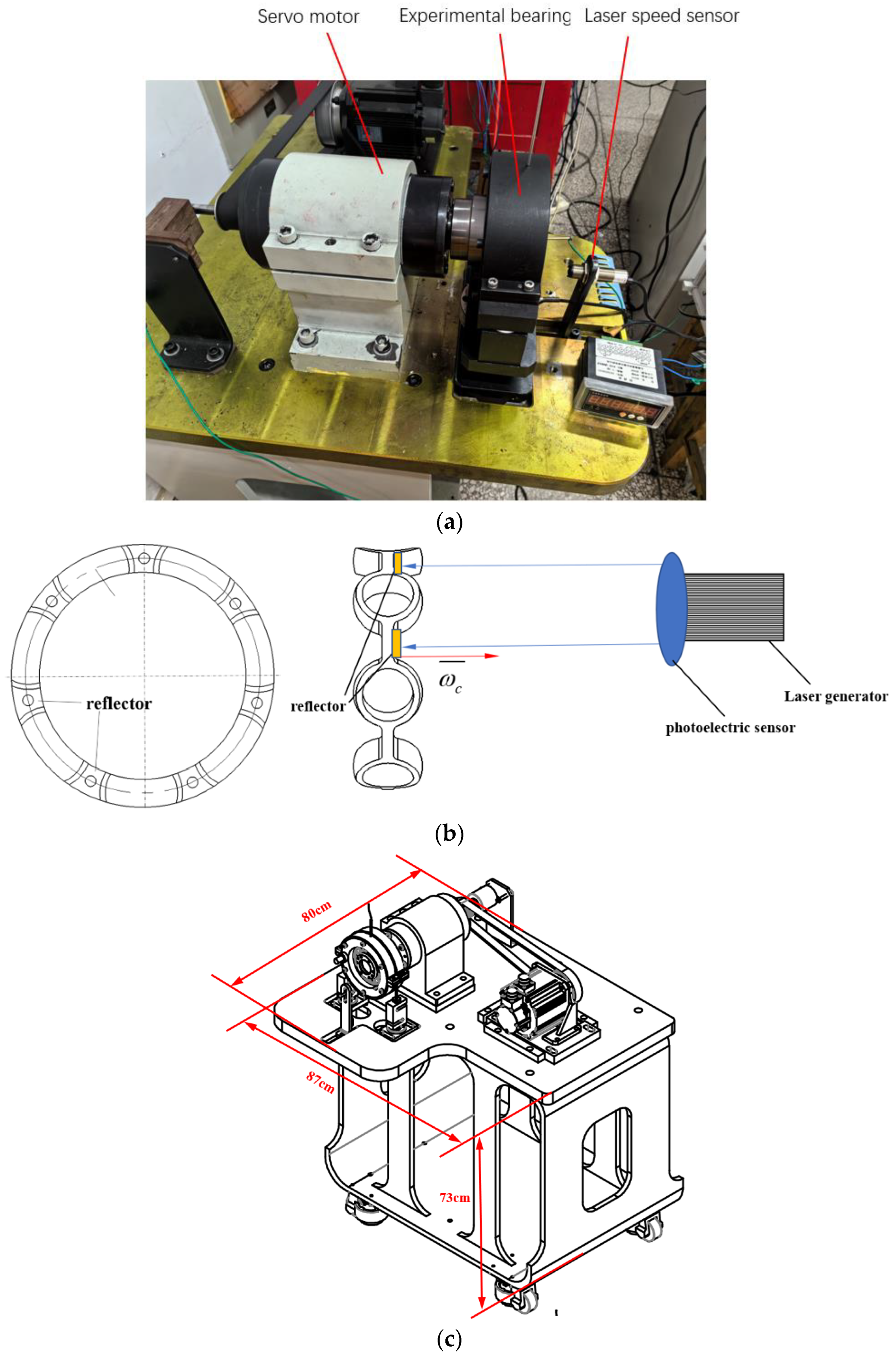
The slipping rate of the bearing cage is an important index to reflect the bearing performance and also to ensure that the test can be carried out normally. Whether the speed of cage can be accurately measured directly affects the judgment of the slipping rate of the cage. To verify the performance of the improved cage proposed in this study, tests were conducted on a test bench, as shown in Figure 11. The main body of the test machine had a cantilever structure; its structural diagram is shown in Figure 11b. The loading bearing was installed on the cantilever end of the testing machine, and the test bearings were used as the fulcrum of the main shaft on which the overturning moment was realized by eccentric loading. The cage speed measurement is shown in Figure 11a. The speed of the cage was measured using a laser velocity measurement. The pocket radius of the original bearing used in the experiment was 3.6 mm and the cage width was 8 mm. The improved bearing pocket radius was 3.46 mm and cage width was 6.1 mm. The model of the laser speed sensor was DK890, and the specific parameters were 10-36VDC, 200 mA. The size diagram of the testing machine is shown in Figure 11c. The Servo motor speed range is 100–11,000 rpm.
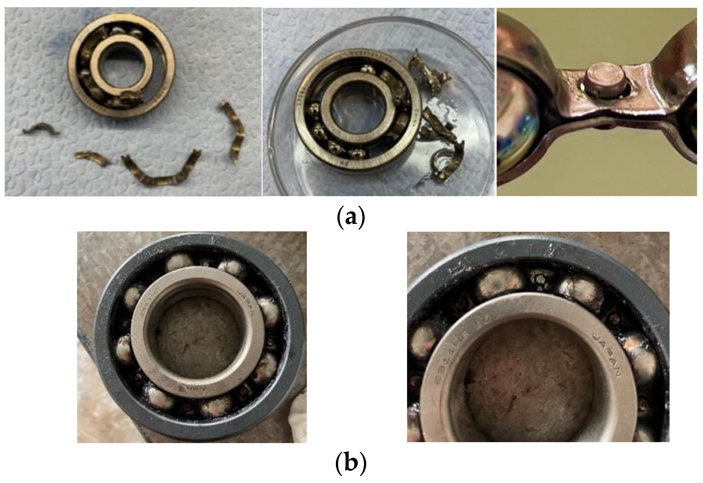
The laser signal returned by the reflector is received by the photoelectric sensor, and every two signals it receives is equivalent to a cage rotation. The cage speed is then automatically displayed on the digital table, and the actual cage speed is recorded by the program. Thus, the slip rate of the cage is obtained, which is calculated using Equation (10). By comparing the results in Table 4, the error between the calculated and experimental values was found to be less than 15%. As shown in Figure 12, the original bearing cage failed before the cage with the improved cage parameters during the test. It can be seen from the enlarged diagram of the failure part that the failure was due to the deformation caused by the fatigue of the metal, and the broken part was at the rivet connection. Therefore, the accuracy of the improved method was verified experimentally.

5. Conclusions

This study analyzed the weak link in an aviation motor that causes early failure of a ball bearing in the aviation motor. The failure analysis of the bearing cage was conducted from the perspective of the cage structure design. The following conclusions were drawn:
(1)
A suitable cage hole radius can significantly reduce the impact force between the steel ball and cage and the stress on the rivet part as well as improve the operational stability of the cage, thus enhancing the adaptability of the working conditions of the bearing cage. The recommended pocket radius of the bearing in this study is approximately 3.46 mm (after normalization, the radius of the pocket is 13.3% of the pitch diameter). A larger coefficient of the groove curvature radius and a smaller radial clearance must be selected within the design range.
(2)
In the wave-pattern holding erection time, the cage wall thickness must be increased within the allowable weight range. This will not have a significant impact on the slip rate of the cage and can improve the strength margin of the cage.
(3)
In the contact to ensure the grease lubrication effect, the cage width is selected near 6 mm (after normalization, the width of cage is 23.1% of the pitch diameter), which can make sure that the impact force between the steel ball and the cage and the stress at the rivet are in the lowest state within the selection range of the cage width.
(4)
The double-half-wave cage rivet and rivet hole in a small-gap matching state are conducive to extending the life of the rivet and preventing its premature fatigue failure.
(5)
Due to the limitation of the space inside the experiment, the impact force between the cage and the ball and the tilt angle of the cage cannot be directly measured. At present, only the slip rate is used to verify the accuracy of the simulation and evaluate the rationality of the bearing design. In future work, more accurate experimental instruments should be used to carry out deeper research.

Author Contributions

Methodology, Y.C.; Validation, X.G.; Data curation, J.W.; Writing—original draft, L.C. All authors have read and agreed to the published version of the manuscript.

Funding

This work was supported by the National Science Foundation for Young Scientists of China (52005158) and the Innovation Platform Project of Aero Engine Power Transmission Key Laboratory of the Aero Engine Corporation of China (CXPT-2023-020).

Data Availability Statement

Data are contained within the article.

Conflicts of Interest

Author Yongcun Cui was employed by the company Changzhou NRB Corporation. The remaining authors declare that the research was conducted in the absence of any commercial or financial relationships that could be construed as a potential conflict of interest.

References

  1. Deng, S.E.; Jia, Q.Y.; Xue, J.X. Design Theory of Rolling Bearings, 2nd ed.; Standards Press of China: Beijing, China, 2014; pp. 258–260. (In Chinese) [Google Scholar]
  2. Gupta, P.K.; Paul, B. Advanced Dynamics of Rolling Elements. J. Appl. Mech. 1986, 53, 731–732. [Google Scholar] [CrossRef]
  3. Rivera, M.P. Bearing-Cage Frictional Instability—A Mechanical Model. Tribol. Trans. 1991, 34, 117–121. [Google Scholar] [CrossRef]
  4. Donley, A.D.; Boesiger, E.A.; Loewenthal, S. An Analytical and Experimental Investigation of Ball Bearing Retainer Instabilities. J. Tribol. 2008, 114, 530–538. [Google Scholar]
  5. Salam, I.; Tauqir, A.; Haq, A.U.; Khan, A.Q. An aircrash due to fatigue failure of a ball bearing. Eng. Fail. Anal. 1998, 5, 261–269. [Google Scholar] [CrossRef]
  6. Ejaz, N.; Salam, I.; Tauqir, A. Failure analysis of an aero engine ball bearing. J. Fail. Anal. Prev. 2006, 6, 25–31. [Google Scholar] [CrossRef]
  7. Ejaz, N.; Ali, L.; Rizvi, S.A. Failure of an aero engine ball bearing due to axial loading. J. Fail. Anal. Prev. 2015, 15, 15–24. [Google Scholar] [CrossRef]
  8. Wei, M.; Dyson, J.; Darvell, B. Failure analysis of the ball bearings of dental air turbine handpieces. Aust. Dent. J. 2013, 58, 514–521. [Google Scholar] [CrossRef]
  9. Mishra, R.K.; Muduli, S.K.; Srinivasan, K.; Ahmed, S.I. Failure analysis of an inter-shaft bearing of an aero gas turbine engine. J. Fail. Anal. Prev. 2015, 15, 205–210. [Google Scholar] [CrossRef]
  10. Kishore, K.; Mukhopadhyay, G. Root cause failure analysis of pinch roll bearing at hot strip mill. J. Fail. Anal. Prev. 2019, 19, 219–229. [Google Scholar] [CrossRef]
  11. Xing, C.; Sun, M. Fatigue fracture mechanism of cage of aero-engine spindle bearing. Aero Engines 2002, 2, 32–34. (In Chinese) [Google Scholar]
  12. Chen, L.; Zhang, Y.; Zhao, Y.; Yang, W. Failure analysis of aero-engine bearings. Aviat. Manuf. Technol. 2015, 128, 120–123. (In Chinese) [Google Scholar]
  13. Niu, R.; Luo, R.; Wang, Y.; Li, H.; Deng, S. Dynamic characteristics of angular contact ball bearings considering wear effects. J. Vib. Shock 2022, 41, 84–93. [Google Scholar]
  14. Tu, W.; Liang, J.; Yang, J.; Yang, B.; Zhang, G.; Yuan, X. Dynamic analysis of impact contact characteristics of the cage of a rolling bearing under variable working conditions. J. Vib. Shock 2022, 41, 278–286. [Google Scholar]
  15. Lu, L.; Shuai, H.; Kai, Z. Analysis of roller bearing cage broken under high DN value. J. Aerosp. Power 2020, 35, 2115–2122. [Google Scholar]
  16. Pang, B.; Qiao, S.; Deng, S. Improved design of cage and strength analysis based on ANSYS. J. Mech. Transm. 2010, 34, 76–78. [Google Scholar]
  17. Cui, Y.C.; Deng, S.E.; Zhang, W.H.; Chen, G. The impact of roller dynamic unbalance of high-speed cylindrical roller bearing on the cage nonlinear dynamic characteristics. Mech. Mach. Theory 2017, 118, 65–83. [Google Scholar]
  18. Cui, Y.C.; Deng, S.E.; Deng, K.W.; Liao, H.; Zhang, W. Experimental study on impact of roller imbalance on cage stability. Chin. J. Aeronaut. 2021, 34, 248–264. [Google Scholar] [CrossRef]
  19. Cui, Y.; Cai, L.; Zhang, S.; Cui, Y.; Deng, S. Study on Fatigue Characteristics of Rivets in Bearing Cage for an Aeroengine Transmission System. Machines 2023, 11, 700. [Google Scholar] [CrossRef]
  20. Zhang, W.; Hu, Y.; Deng, S.; Xu, J.; Li, F. Collision Behavior between Ball and Cage in Ball Bearing during Oscillating. Acta Armamentrii 2022, 43, 207–217. [Google Scholar]
  21. Jia, X.; Zhang, W.; Zhao, B.; Cui, C.; Deng, S. Influence of Structural Parameters of Deep Groove Ball Bearing Crown Cage on Its Performance. Bearing 2021, 13–19. [Google Scholar] [CrossRef]
  22. Arya, U.; Sadeghi, F.; Conley, B.; Russell, T.; Peterson, W.; Meinel, A. Experimental Investigation of Cage Dynamics and Ball-Cage Contact Forces in an Angular Contact Ball Bearing. Proc. Inst. Mech. Eng. Part J J. Eng. Tribol. 2022, 236, 2522–2534. [Google Scholar] [CrossRef]
  23. Yuan, D.; Wang, R.; Chen, S.; Chen, X. Experimental research on cage motion with different pocket shapes in angular contact ball bearing. Proc. Inst. Mech. Eng. Part J J. Eng. Tribol. 2022, 236, 1325–1335. [Google Scholar] [CrossRef]
  24. Chen, S.; Chen, X.; Shuai, Q.; Gu, J. Effects of Cage Pocket Shapes on Dynamics of Angular Contact Ball Bearings. Tribol. Online 2020, 15, 343–355. [Google Scholar] [CrossRef]
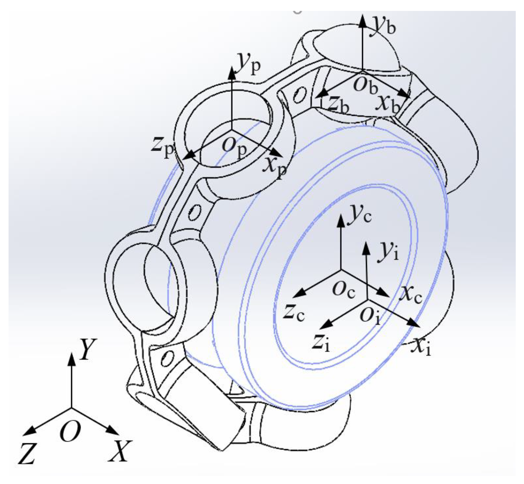
Figure 1. Coordinate systems in a bearing.
Machines 12 00466 g001
Figure 2. Force between the ball and the inner and outer raceways.
Machines 12 00466 g002
Figure 3. Force acting between the ball and the cage’s pockets.
Machines 12 00466 g003
Figure 4. Stress concentration diagram of cage connection part. (a) Result of modified Norbert method. (b) Result of finite element calculation.
Machines 12 00466 g004
Figure 5. Relationship between pocket radius and cage dynamic contact characteristics. (a) Relationship between impact force of steel ball and cage and radius of pockets. (b) Relationship between maximum rivet stress and pocket radius. (c) Relationship between cage dynamic characteristics and radius of pockets. (d) Relationship between cage stability and radius of pockets.
Machines 12 00466 g005
Figure 6. Relationship between cage width and contact characteristics between ball and cage. (a) Relationship between impact force of the steel ball and cage and width of the cage. (b) Relationship between maximum stress at rivet position and cage width. (c) Relationship between cage dynamic characteristics and cage width.
Machines 12 00466 g006
Figure 7. Relationship between thickness and contact characteristics between ball and cage. (a) Relationship between impact force and maximum stress of rivet and cage thickness. (b) Relationship between the maximum rivet stress and cage thickness.
Machines 12 00466 g007
Figure 8. Relationship between cage structure parameters and impact force.
Machines 12 00466 g008
Figure 9. Relationship between channel structure parameters and cage dynamic contact characteristics. (a) Relationship between impact force and coefficient of curvature radius of inner raceway. (b) Relationship between slipping rate, cage tilt angle, and inner raceway curvature radius coefficient. (c) Relationship between impact force and curvature radius coefficient of outer raceway. (d) Relationship between slipping rate, cage tilt angle of cage, and curvature radius coefficient of outer raceway. (e) Relationship between impact force and radial clearance between steel ball and cage. (f) Relationship between slipping rate, cage tilt angle, and cage radial clearance.
Machines 12 00466 g009aMachines 12 00466 g009b
Figure 10. Effect of the fit relation on stress distribution at the rivet position. (a) Stress distribution in the rivet in interference-fit with the cage. (b) Stress distribution in the rivet in gap-fit with cage clearance. (c) Relationship between the fit clearance and maximum stress in the rivet.
Machines 12 00466 g010
Figure 11. Test machine and each experimental component diagram. (a) Photograph of testing machine. (b) Schematic of cage speed measurement. (c) Testing machine size diagram.
Machines 12 00466 g011
Figure 12. Photographs of tested bearings. (a) Original bearing test result. (b) Experimental results of bearings with improved cage parameters.
Machines 12 00466 g012
Table 1. Main structural parameters and working conditions of the bearing.
ParameterValue
Bearing outer diameter/mm37
Bearing inner diameter/mm15
Pitch diameter of the ball/mm26
Ball diameter/mm6.47
Pitch diameter/mm26
Bearing width/mm10
Cage width/mm6.5
Pocket radius/mm3.45
Speed/r/min9000
Overturning moment/N·mm82,500
Table 2. Main material parameters of the bearing.
Component NameMaterialDensity/(g/cm3)Elastic Modulus/GPaPoisson Ratio
Inner(Outer) ring and ballGCr157.852050.291
cageML157.821920.3
Table 3. Full-factor test results.
No.Pocket Radius/mmCage Width/mmQcj/NNo.Pocket Radius/mmCage Width/mmQcj/N
13.43834.67263.465.625.47
23.437.432.373273.46527.07
33.436.829.837283.464.430.841
43.436.229.657293.47831.24
53.435.629.932303.477.427.85
63.43531.1313.476.825.87
73.434.433.582323.476.225.51
83.44832.667333.475.625.86
93.447.428.821343.47527.28
103.446.827.24353.474.430.977
113.446.226.27363.48832.27
123.445.627.23373.487.428.61
133.44528.74383.486.826.57
143.444.432.85393.486.226.33
153.45831.345403.485.626.68
163.457.427.934413.48528.46
173.456.825.83423.484.432.53
183.456.225.49433.49834.42
193.455.625.98443.497.430.538
203.45527.251453.496.827.93
213.454.431.107463.496.228.734
223.46831.162473.495.627.96
233.467.427.61483.49530.071
243.466.825.48493.494.433.9
253.466.225.12
Table 4. Experimental result of slipping rate.
Bearing Load and SpeedModified BearingOriginal Bearing
Experimental ValueArtificial ValueExperimental ValueArtificial Value
82,500 N·mm
9000 rpm
1.13%1.04%1.84%1.67%
82,500 N·mm
8000 rpm
1.07%0.94%1.35%1.27%
82,500 N·mm
7000 rpm
0.97%0.92%1.14%1.05%
Disclaimer/Publisher’s Note: The statements, opinions and data contained in all publications are solely those of the individual author(s) and contributor(s) and not of MDPI and/or the editor(s). MDPI and/or the editor(s) disclaim responsibility for any injury to people or property resulting from any ideas, methods, instructions or products referred to in the content.