Article

Brush Seal Performance with Ideal Gas Working Fluid under Static Rotor Condition

by
Altyib Abdallah Mahmoud Ahmed
1,2,*,
Meihong Liu
1,*,
Yuchi Kang
1,
Juan Wang
1,
Aboubaker I. B. Idriss
2,3 and
Nguyen Thi Trung Tin
1
1
Faculty of Mechanical and Electrical Engineering, Kunming University of Science and Technology, Kunming 650500, China
2
Mechanical Engineering Department, Faculty of Engineering Science, Nyala University, Nyala 63311, Sudan
3
College of Mechanical and Electrical Engineering, Northeast Forestry University, Harbin 150040, China
*
Authors to whom correspondence should be addressed.
Machines 2024, 12(7), 476; https://doi.org/10.3390/machines12070476
Submission received: 13 June 2024 / Revised: 5 July 2024 / Accepted: 11 July 2024 / Published: 15 July 2024
(This article belongs to the Section Turbomachinery)

Abstract

:
The study investigated how variations in pressure ratio affect the leakage flow of a brush seal for both contact and clearance structures, in which the clearance is measured as the distance between the bristles tip and the rotor surface. This investigation utilized the Reynolds-Averaged-Navier–Stokes (RANS) equations alongside a two-dimensional axisymmetric anisotropic porous medium model. To verify the model’s accuracy and dependability, the obtained results were compared with previous numerical results and experimental observations, showing a satisfactory level of agreement. The results indicate that the predominant pressure drop occurs downstream of the bristle pack with the clearance model exhibiting a higher leakage rate compared to the contact model. Leakage increases proportionally with the pressure ratio, while axial velocity gradually rises and radial velocity experiences a significant increase. In conclusion, the leakage in the brush seal contact structure is significantly lower than in the clearance structure, resulting in the best performance.

1. Introduction

A brush seal represents a form of contact seal technology. According to Figure 1, a common brush seal comprises slender bristles densely arranged between the front and pack plates.
Based on the research of Bayley and Long (reference provided), it was determined that the distance between the bristles ranges between ((bristle diameter)/7) and ((bristle diameter)/10) or (0.007 and 0.010) mm. Consequently, a bristle gap of (bristle diameter)/8 mm was selected as equal to 0.009525 mm. A brush seal is typically made of two plates, a front plate and a back plate, that partially enclose the bristles. The bristle pack material, the density at which they are packed, the amount of clearance or interference between the rotor surface and the bristle pack, the heights of the front and back plates, the angle at which the bristles are inclined, and the methods used to balance the pressure on the two sides of the seal can all vary depending on the specific design [1,2,3]. Throughout the operational condition, the brush seal contacts the corresponding rotor. The only gaps that permit leakage flow through the seal are those located within the bristle region corresponding to the fence height. When compared to other types of seals, brush seals can significantly reduce the rate of leakage and require less axial space [4]. Brush seals are now more frequently used in steam turbines and industrial gas turbines, either alone or in combination with labyrinth seals, to greatly increase the power output and efficiency capacities despite their original design being for aero-engines [5,6].
Comparing the brush seal to the labyrinth seal, leakage can be reduced by 70 percent [7]. In addition to dramatically decreasing leakage loss at the dynamic and static gaps, the brush seal can also do so for the entire system [8]. Although brush seals cost more to produce than labyrinth seals, they have a much greater potential for long-term cost savings [9]. Due to the substantial sealing clearance inherent between the labyrinth teeth and the shaft, clearance brush seals exhibit sealing performance similar to that of labyrinth seals [5]. Due to friction, brush seals can produce a lot of heat, especially at high rotor speeds and high pressure. The bristles are normally inclined in the direction of rotation and angled between 30 and 60 degrees from the shaft; this helps to decrease the friction and heat generation [10]. Investigating how brush seals control leakage and heat transfer is important to ensuring sealing performance and durability over time. In this study, a thorough numerical simulation of the leakage characteristics of brush seals will be conducted using computational fluid dynamics (CFD). The study will thoroughly study the flow patterns within the brush seal using a two-dimensional axisymmetric, anisotropic porous media model to investigate the performance of the brush seal.
There are two basic groups of the brush seal numerical simulation: those that simulate the bristle pack as a physical entity and those that consider it as a porous medium. The entity model consists of two unique models: the 2D and 3D tube bank models, both of which are practical choices, and the 3D tube bank model, which is used to study the anisotropic flow in the bristle pack but requires a lot of computing resources, time, and power [11]. In the field of brush seals, the porous media model is a hot topic. However, calibrating resistance coefficients within the brush seal bristle pack is time consuming and expensive [12].
Chew et al. [13,14] investigated the non-uniform porosity within the bristle pack and developed a computational approach for determining the resistance coefficient of the bristle pack based on pressure distributions in various orientations. Prostler [15] created a three-dimensional computational method for the porous medium model. Dogu [16] calculated the viscous resistance coefficient of the axial direction using Darcy’s law and Bernoulli’s equation and then calibrated the resistance coefficient of the radial direction using experimental data. Wiid [17] used the water flowing through the bristle pack to compute the resistance coefficient.
Thomas et al. [18] studied how the permeability of brush seals changes when they are modeled as a porous medium. They found that the viscous effect, such as friction between the bristles and the fluid, is the most important factor in determining the leakage through the brush seal.
Bayley and Long [19] conducted an experimental investigation aimed at calibrating the coefficients of a porous media model for brush seals. This involved measuring leakage flow and pressure distribution for brush seals with an interference structure of 0.25 mm and subsequently utilizing the experimental data to calibrate the model coefficients.
Many scholars, including [20,21,22], have explored the leakage performance of brush seals analytically, experimentally, and numerically. The results demonstrated that the numerical and experimental results are in excellent agreement.
The tube bank model is commonly applied in thermal fluid machinery contexts, such as heat exchangers in boilers and air conditioners, and is employed in numerical simulations to analyze the performance of brush seals. Researchers typically utilize the tube bank model for examining brush seal performance.
Several experiments and numerical simulations have been investigated over the last ten years to investigate how well brush seals reduce leakage. These investigations helped our comprehension of the leakage flow attributes of brush seals, which is crucial for their efficient design and utilization [23,24,25].
This paper presents a new method for modeling the brush seal that is more accurate and efficient than previous methods. The method uses a 2D axisymmetric model to determine the resistance coefficients of brush seals, which are then used to create a porous medium model of the brush seals. The effects of the pressure ratio on the leakage flow of contact and clearance brush seals will be discussed. This method combines the advantages of the 2D axisymmetric model and the porous media model, allowing for the simulation of flow anisotropy and the visualization of brush seals. Additionally, this method provides a convenient alternative to designing and analyzing brush seals, which can save time and money on the calibration of the porous media model.

2. Numerical Approach for the Leakage Flow Characteristic of the Brush Seal

The objective of this paper is to discuss a numerical method for simulating a brush seal bristle pack. The approach provides a current summary of geometry, mesh, boundary conditions, solver, and the porous medium model that was used.

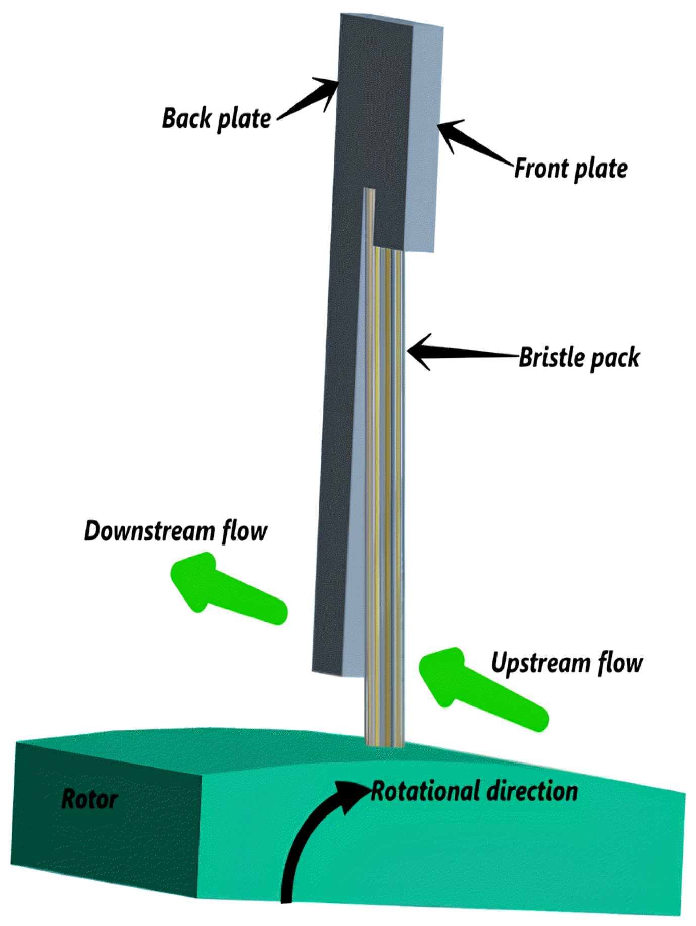
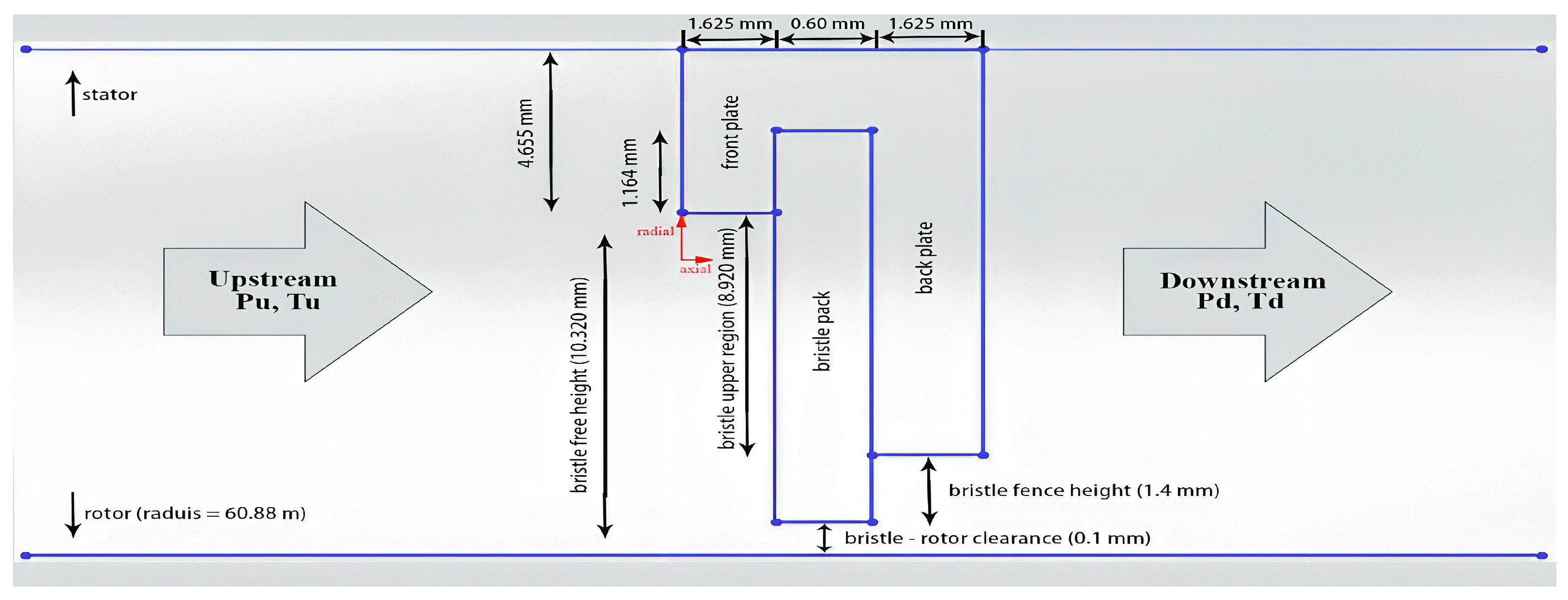
2.1. Problem Description

The brush seal is composed of three main components: the front plate, the bristle pack, and the back plate [26]. A brush seal is constructed by clamping the end of the bristle pack assembly between the front and back plates. The brush seal operates by making contact with the adjacent rotor. The leakage flow is restricted to the passage through voids located between the bristles within the region of the fence height. In comparison to other types of seals, brush seals exhibit a significant reduction in leakage flow and need a smaller axial area.

2.2. Theoretical Approach of Porous Medium

When using the porous media model to analyze the leakage characteristic and pressure distribution of the brush seal, some assumptions must be made.
  • Ignore the influence of shaft curvature.
  • Reasonably ignores bristle bending.
  • The leakage of air from the brush seal is an ideal compressible gas.
  • The bristles that make up the brush seal are made of Haynes 25 and are uniform in shape.
  • The bristles are not drawn individually; instead, the entirety of the region is considered a porous medium.
According to the mentioned assumptions, this study employs the Reynolds-Averaged Navier–Stokes (RANS) equations to characterize the resistance coefficients. This entails incorporating a resistance source term into the RANS equation, encompassing both the inertial and viscous resistance terms [27].
( ρ u i u j ) x j = p x i + τ i j x j + F i
F i = A i η u i 1 2 B i ρ | u | u i
A i and B i in Equation (2) represent the viscous resistance coefficient and the inertial resistance coefficient inside the porous medium of the bristle pack. Because the rotor is in a stationary state in the present investigation and the circumferential velocity is so low, the CFD analysis was carried out in two dimensions: the radial direction (r-axis) and axial direction (z-axis), and we assume constant values for A and B, ignoring the influence of pressure ratio in Equation (2) on resistance coefficients. Table 1 lists the calibrated coefficients as provided by Dogu [16].
Equation (1) is known as the momentum equation, and F i represents the additional resistance source term of the porous medium. The porosity, denoted as ε , is the ratio of void volume to total volume, which includes both voids and bristles. The brush seal’s structural parameters control the relationship between the porosity and radial size of the bristle pack [27,28]. The brush seal porosity can be clearly shown in Equation (3).
ε = 1 V s V = 1 π D 2 N D r 8 r ω sin φ
where the variables V s and V represent the bristle and total volume of the porous media area, respectively. N represents the bristle pack density, which is measured in bristles per unit length. Dr represents the rotor diameter, while r represents the radial height of the bristle. The variable ω represents the axial thickness of the bristle pack, while φ represents the bristle lay angle, which is measured in degrees. In this current study, the porosity of the bristle pack in the brush seal has been ascertained as 0.195 and further validated with experimental data referenced from [4,23].

3. Porous Media Solver Model for Brush Seal

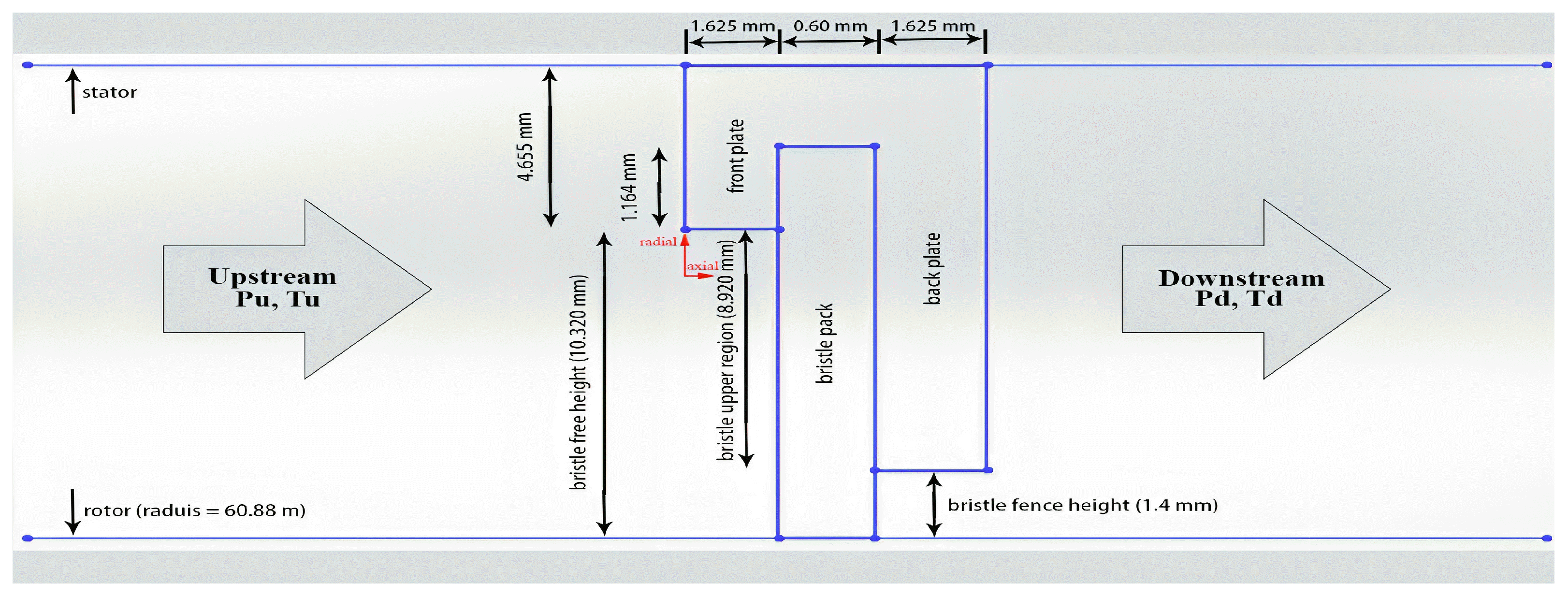
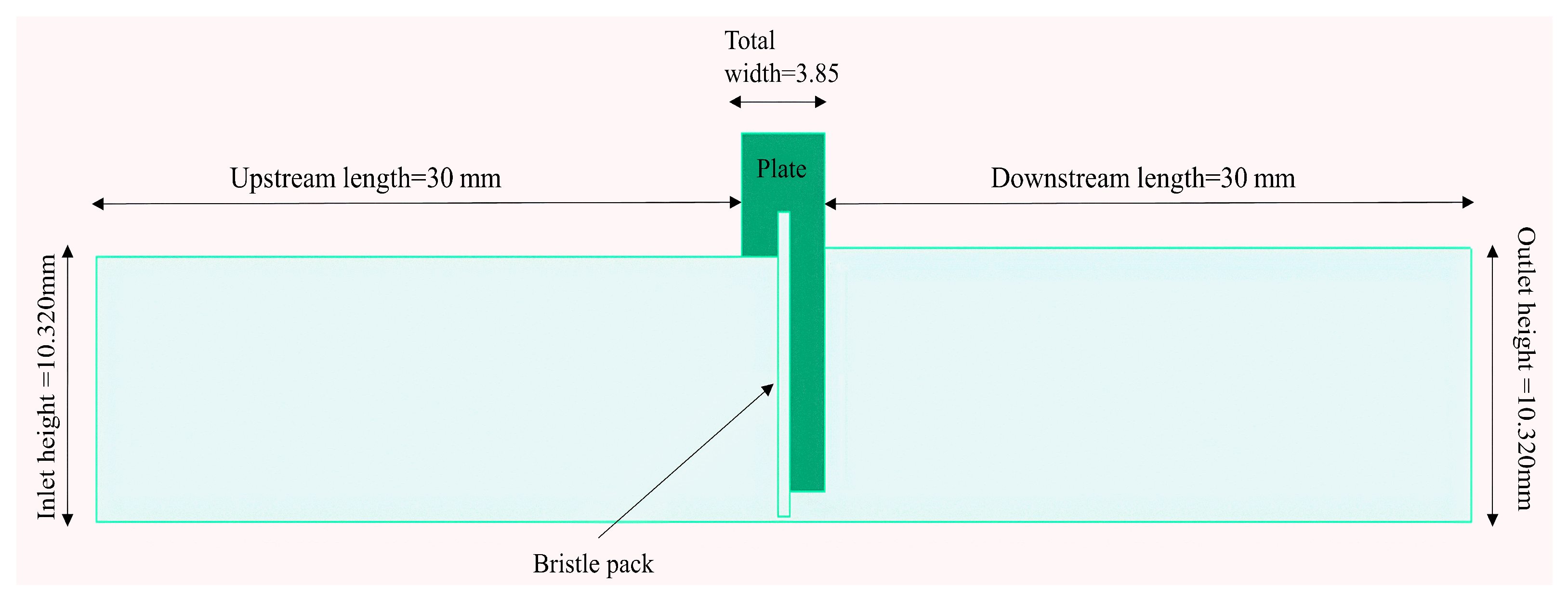
3.1. Geometric Specifications

This study selects a two-dimensional axisymmetric model to investigate the leakage flow characteristic of the brush seal. The clearance and contact are two structural cases between the rotor and the bristle pack. The calculation domain is divided into multiple areas, including the upstream high-pressure area, the porous medium area for the bristle pack, and the downstream low-pressure area. Because this CFD model is based on the seal tested by Bayley and Long [19] and the numerical simulation conducted by Qiu et al. [29], it is critical to compare the model to the existing experimental data. Table 2 and Figure 2 and Figure 3 present an extensive list of the detailed geometric specifications of the brush seal.
To reduce the effects of upstream and downstream cavities, the lengths of the outlet and inlet zones are axially extended to three times the brush seal radial height [30]. Therefore; we are currently increasing the upstream and downstream lengths, as can be seen in Figure 4. The estimated bristle pack thickness of the investigated brush seal in reference [29] is 0.64 mm; however, our bristle pack thickness in this study is 0.60 mm. The inlet height was chosen as a reference dimension, which was equal to 0.01032 m.

3.2. Boundary Conditions

The inlet pressure, outlet pressure, and temperature are all used to establish boundary conditions. The outlet static pressure is maintained at 0.1 MPa, while the inlet total pressure rises from 0.2 to 0.6 MPa, resulting in a pressure ratio of R p 2 to 6. The inlet air temperature is 293 K. All walls are adiabatic, and the shear condition has no slip. The rotor’s surface is also stationary. Air has been selected as the working fluid and is considered an ideal gas. Table 3 shows how the periodic boundary condition is employed in a 2D axi-symmetric model.

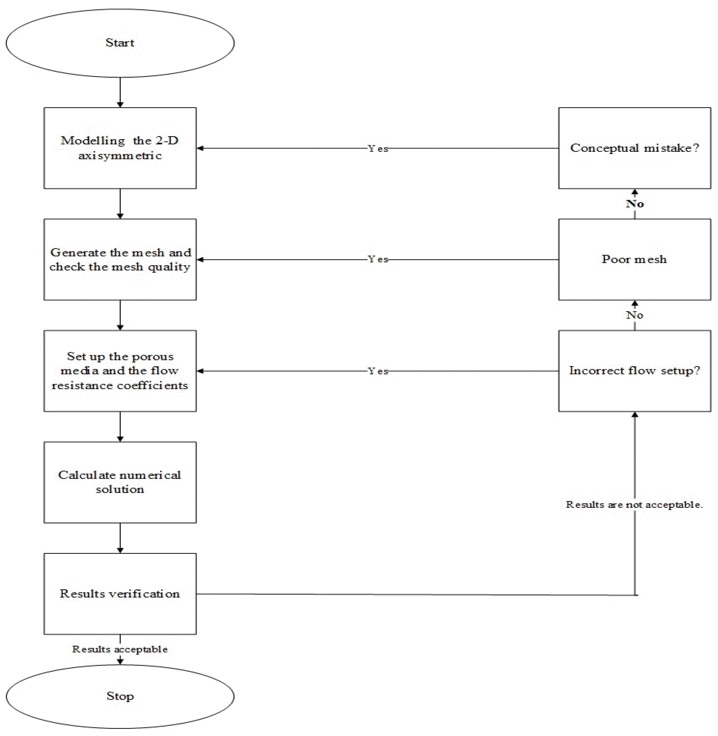
3.3. Numerical Methods

The governing equations are solved using the commercial software ANSYS Workbench 2022 R1. The 2D steady state and pressure-based solver have been used to solve the 2D axisymmetric model using the porous media method. The porous medium model uses the axisymmetric swirl model. The SIMPLE algorithm, the second-order upwind difference method, and the RNG k-epsilon model are applied. The bristle pack region is defined using the porous media approach. Figure 5 shows the flow chart for calculation analysis [31].

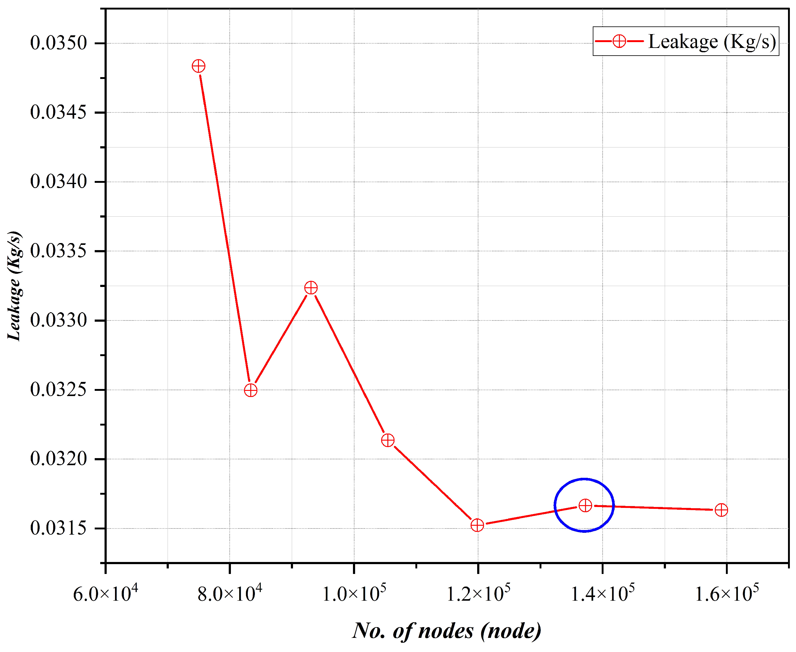
3.4. Mesh Quality Inspection

Figure 6 represents the leakage rates for various mesh sizes (at a pressure ratio of 2). As observed, there are no significant differences in results for grids with more than 137,235 nodes. Figure 7 and Figure 8 show the equivalent mesh layout. As can be seen, the structure mesh is selected, and the mesh is denser in the porous medium zone (bristle pack) to obtain accurate results.

3.5. Validating the Precision of the Porous Medium Model

The brush seal leakage flow under the numerical calculation model proposed in the present study was validated through a comparison with the results presented in the references [19,29]. The figure depicts an increasing pattern in leakage observed in the current study, which is consistent with both experimental and simulation results. As shown in Figure 9, our current computational fluid dynamics (CFD) simulation of the contact structure shows the lowest rate of leakage at all pressure ratios when compared to the other supplied case values. The accuracy of the model was validated, and the comparison demonstrated that there is a reasonable agreement with the previous results, as shown in Figure 9.

4. Results and Discussions

The interference and contact structures have the same geometrical topology in the 2D CFD model domain; hence, the interference structure was not incorporated into the modeling we conducted for this research. The bristle pack in the fence height zone obstructs the flow, and the filtering flow through the bristles flows into the downstream region. The effect of the pressure ratio on the leakage, pressure distribution, and velocity distribution for contact and clearance brush seals is numerically investigated using the presented numerical method, and the results are shown in the following section.

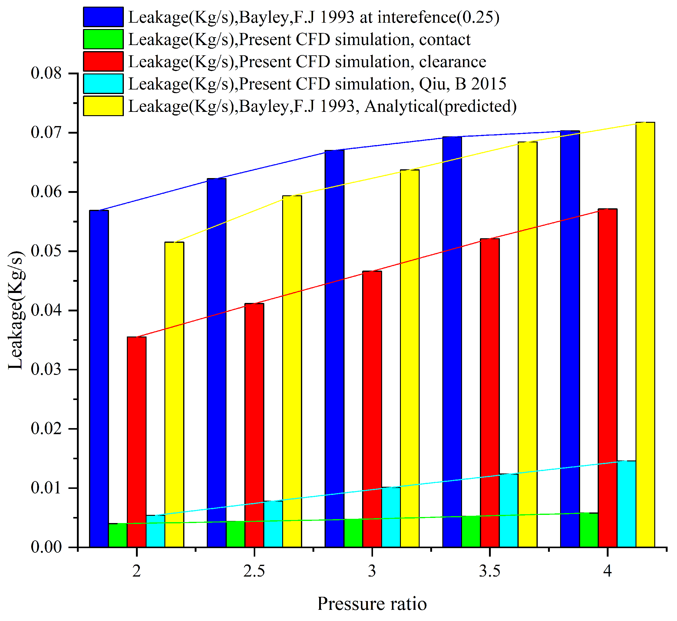
4.1. Leakage Flow with Different Pressure Ratios

Figure 10 shows the leakage distribution at different pressure ratios. It was observed that the leakage flow increases as the pressure ratio increases. However, the rate of increase in clearance brush seal is linear. In contrast, the rate of increase in the contact brush seal exhibits a nearly linear relationship with the same increase in pressure ratio. However, the maximum difference between them does not exceed 8 percent. This demonstrates that the pressure ratio increases the brush seal leakage. However, excessive increases in leakage are undesirable, and herein lies the importance of the contact brush seal model to control it more effectively than the clearance brush seal model.

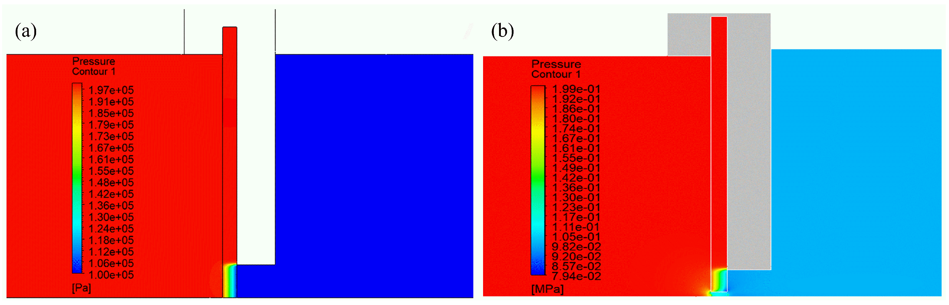
4.2. Pressure Contour Distribution

Fluid pressure remains relatively consistent in the upstream region with a stationary rotor, a bristle fence height of 1.4 mm, and inlet/outlet pressure ratios of 2 and 6. Figure 11 and Figure 12 illustrate a decrease in fluid pressure across the contact and clearance brush seals, especially within the bristle pack fence height region, indicating the influence of the brush seal bristle pack on fluid sealing performance.

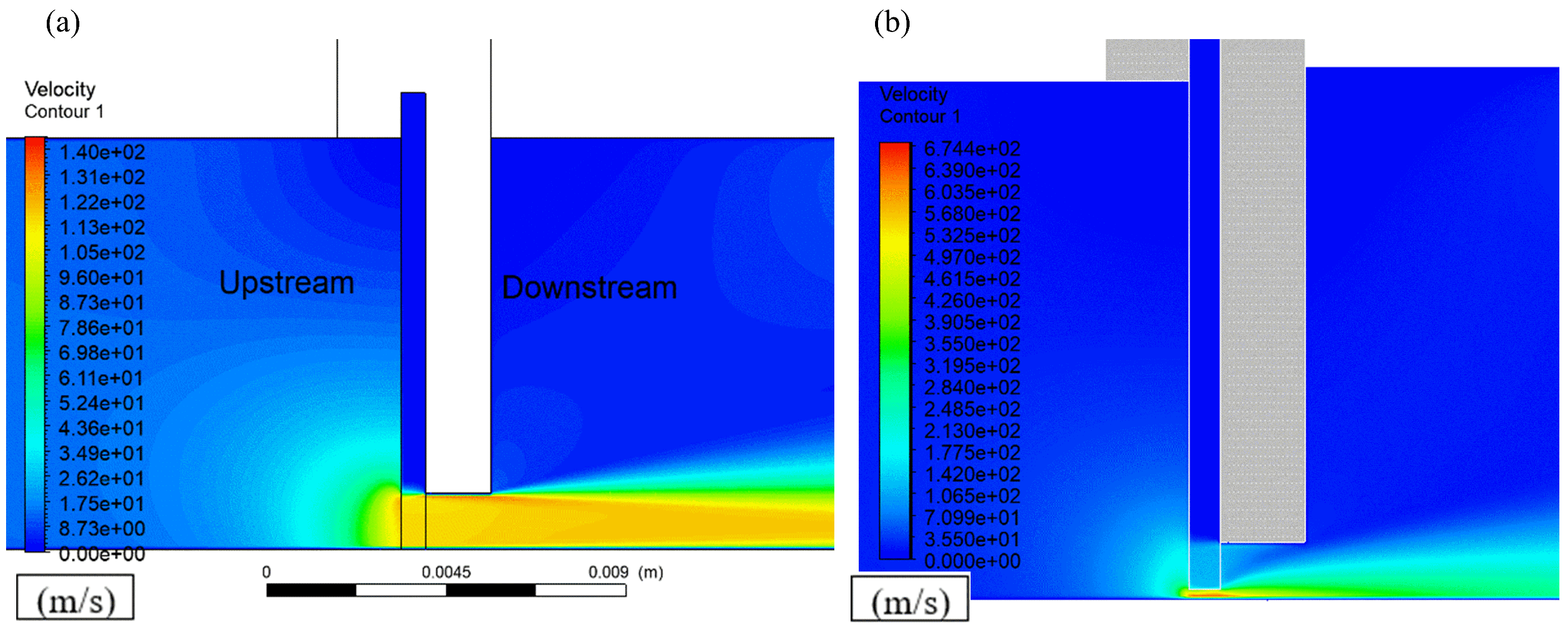
4.3. Velocity Contour Distribution

With a stationary rotor, a bristle fence height of 1.4 mm, pressure ratios of 2 and 6, fluid moves from the upstream to the downstream side of the brush seal bristle pack. The velocity of the flow begins to increase within the area of the brush seal bristle pack near the back plate. As a result of the pressure decrease, the fluid velocity peaks beneath the back plate and further increases before exiting as a jet (refer to Figure 13 and Figure 14).

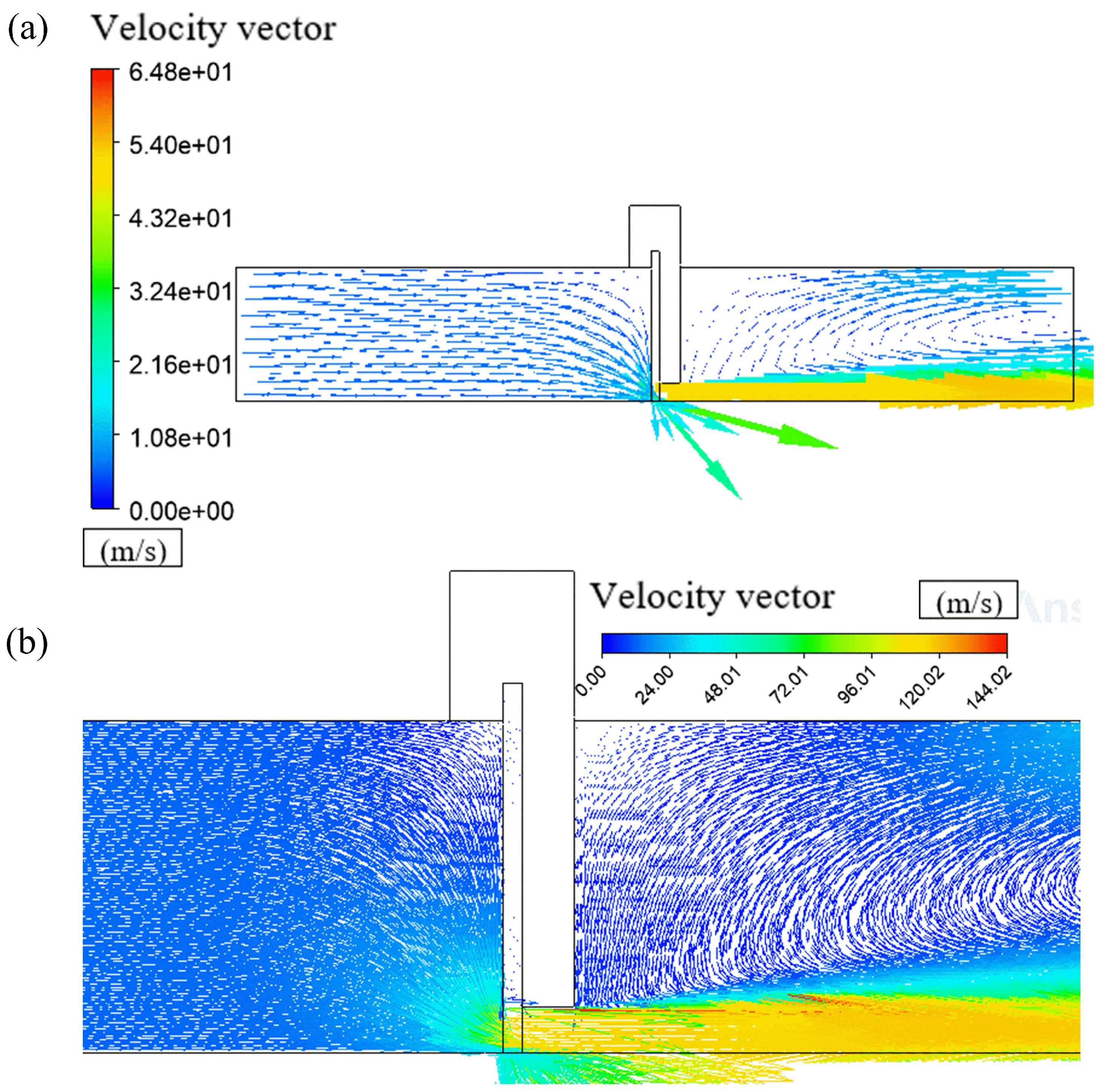
4.4. Velocity Vector Distribution

The velocity vector distribution in the brush seal bristle pack, particularly in the fence height zone at a pressure ratio of 2 and 6, is shown in Figure 15 and Figure 16. The fluid in the upstream direction comes into touch with the porous medium region, whereas the flow that exits through the upstream face enters the bristle pack. The flow that enters the system exhibits axial movement inside the fence height zone and then leaks downstream. The airflow that leaks in the air gap between the bristles and the backing plate descends toward the surface of the rotor, mixing with the axial leakage flow in the range of the fence height and moving downstream.

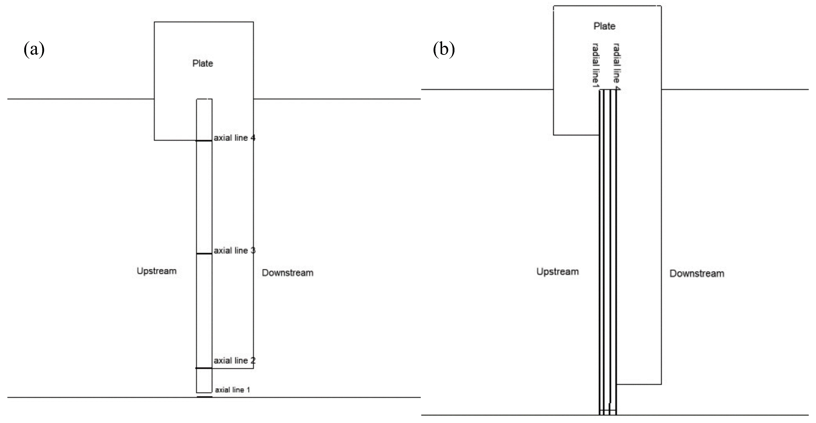
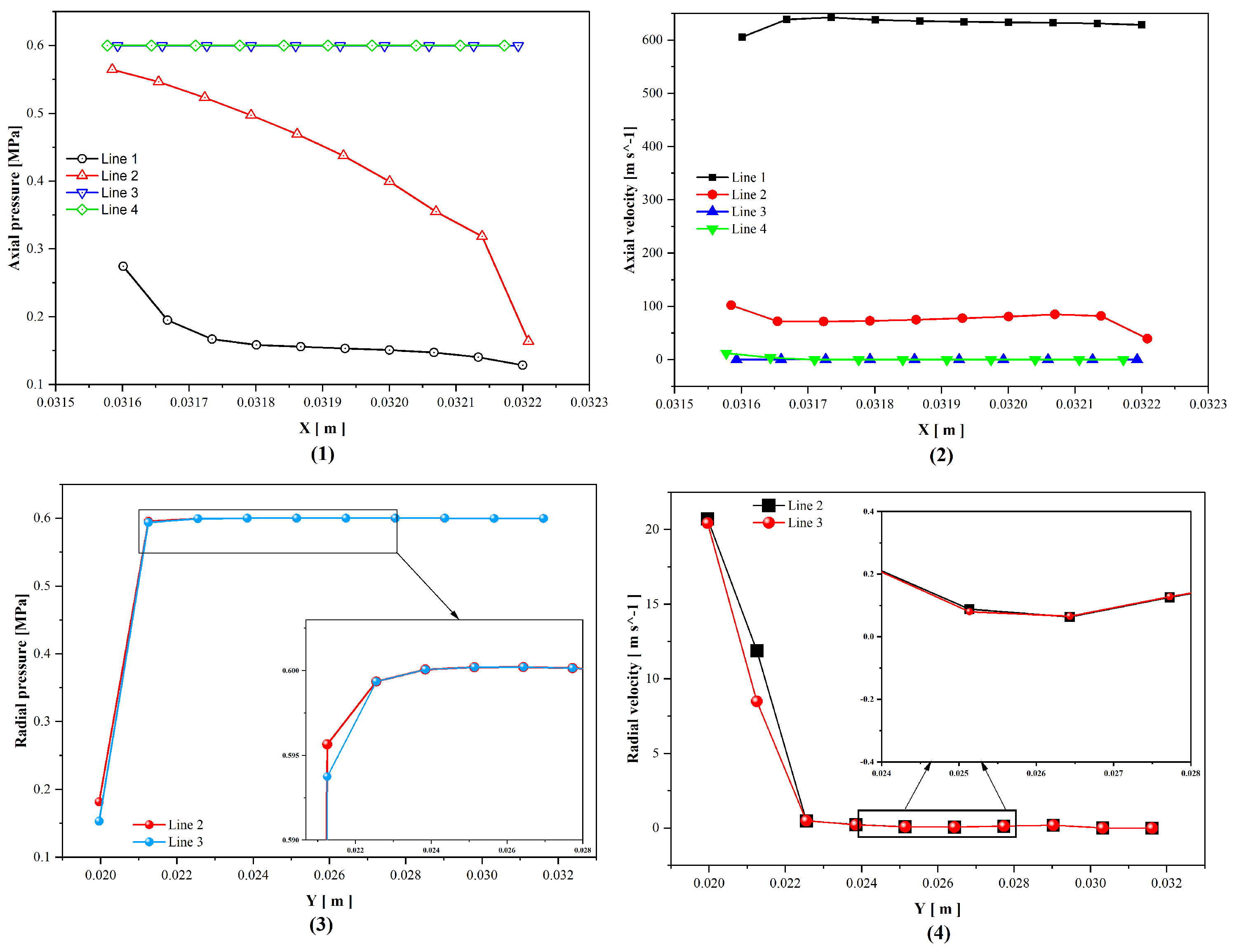
4.5. Radial and Axial Velocity and Pressure in Brush Seals at Contact and Clearance Structures

This section presents pressure and velocity lines within the clearance and contact brush seal configurations. Pressure and velocity data are extracted at three radial positions (lines 1, 2, and 3) and twelve axial locations represented by lines 1, 4, 8, and 12, as illustrated in Figure 17 and Figure 18, respectively. The brush seal has to endure an axial pressure load. There is a pressure differential over the bristle pack thickness from upstream to downstream. The bristle pack thickness develops variations in pressure that are generally linear from upstream to downstream [19,32]. Around the top of the bristle pack, the pressure change is approximately negligible. Pressure drops are obvious in the fence height of the porous zone. Radial flow increases toward the rotor as the axial diffusive process increases leakage flow. This confirms the observed radial pressure gradient [32]. It is well known that nearly all pressure drops occur on the bristles’ downstream area for the contact seal. Brush seal simulations for the clearance structure are slightly different. Because of the clearance space, the pressure loss is evenly distributed across the bristles. Flow acceleration accelerates the axial flow at the clearance entrance as well. The flow velocity peaks in both the radial and axial directions (Figure 19) and (Figure 20). In both cases, flow velocities are positive. The axial flow in the fence height region is combined with the inward radial flow from the upper region and then enters the downstream region through the rotor surface. The axial velocities of the downstream face of the bristle pack in the fence height zone are relatively high. This velocity tends to pull the bristles from the pack’s final columns toward the downstream side of the fence height region.

5. Conclusions

In the present study, a numerical porous media simulation of brush seals was developed utilizing two models: contact and clearance. A comparative analysis was performed to investigate the impact of pressure ratio on brush seal leakage characteristics, pressure, and velocity distributions under each model. The main conclusions are as follows:
  • In our simulation, the focus was on compressible flow. The model geometry was adopted from the research conducted by Bayley and Long, as in the previous experimental research. From the simulation results, we found that the compressible flow did not have a significant impact on the results. However, the long calculation time associated with the compressible flow model should be considered as a trade-off.
  • While optimal brush seal performance is achieved when the bristle pack maintains full contact with the rotor surface, the practical limitations often necessitate operation with a small clearance structure due to factors such as rotor deviation, transient conditions, or bristle wear.
  • The fluid velocity reached a maximum value near the rotor surface, indicating jet-like behavior at the outlet, and the pressure at the free end of the bristle pack reached its minimum value at this point; furthermore, both contact and clearance structures demonstrated a significant increase in leakage rate with an increasing pressure ratio, but the leakage rate under the contact model consistently remained lower than that of the clearance model, highlighting the superior sealing performance achieved under the contact model.
  • The leakage rates for both the contact and clearance structures increased in different ways as the pressure ratio rose. This shows how important the pressure ratio is when judging the performance of a brush seal. The simulated leakage rate agreed well with both experimental results and previous simulation results across the entire pressure ratio range. This proves that the proposed method for figuring out resistance coefficients in porous media is correct.
  • While the current investigation examined the leakage flow behavior of brush seals under different structural configurations, further research is necessary to investigate the influence of rotor rotations on leakage flow and to characterize the optimal sealing performance under varying operational parameters.

Author Contributions

Conceptualization, M.L. and A.A.M.A.; methodology, A.A.M.A., Y.K., and A.I.B.I.; software, A.A.M.A., Y.K. and N.T.T.T.; validation, M.L. and A.A.M.A.; formal analysis, A.A.M.A.; investigation, A.A.M.A.; resources, A.A.M.A. and J.W.; data curation, A.A.M.A.; writing—original draft preparation, A.A.M.A.; writing—review and editing, M.L. and A.A.M.A.; visualization, A.A.M.A.; supervision, M.L., Y.K.; project administration, M.L.; funding acquisition, M.L. All authors have read and agreed to the published version of the manuscript.

Funding

This work was supported in part by the National Natural Science Foundation of China. The subject project is the establishment of the fluid–solid–thermal coupling model of the brush seal and the dynamic research of the sealing system. Grant No. 51765024.

Data Availability Statement

The original contributions presented in the study are included in the article, further inquiries can be directed to the corresponding authors.

Acknowledgments

The authors thank the National Natural Science Foundation of China for funding support in this section. They are also thankful to Shamseldeen Ismail Abdallah for his advice.

Conflicts of Interest

The authors declare no conflicts of interest.

Nomenclature

The following nomenclature are used in this manuscript:
AiViscous resistance coefficient [1/ m 2 ]
BiInertial resistance coefficient [1/m]
FiAdditional resistance source term of the bristles to the fluid
RpPressure ratio
PiPressure inlet
PdPressure outlet
vaAverage flow velocity
dBristle diameter
VsBristle volume
VTotal volume
NBristle pack density [bristles/unit length]
DrRotor diameter

Greek Symbols

The following Greek symbols are used in this manuscript:
φ Bristle lay angle [degree]
ρ Density [kg/ m 3 ]
ε Porosity (ratio of the void volume to the total volume (voids and bristles))
μ Dynamic viscosity [kg/(m·s)], also can be called friction coefficient

Abbreviations

The following Abbreviations are used in this manuscript:
CFDComputational fluid dynamics
RANSReynolds-averaged Navier–Stokes
2DTwo-dimensional model

References

  1. Pekris, M.J.; Franceschini, G.; Gillespie, D.R. An Investigation of Flow, Mechanical and Thermal Performance of Conventional and Pressure-Balanced Brush Seals. In Turbo Expo: Power for Land, Sea, and Air; American Society of Mechanical Engineers: New York, NY, USA, 2012; Volume 44700, pp. 2141–2153. [Google Scholar]
  2. Li, J.; Yang, J.; Shi, L.; Yang, R.; Feng, Z. Analytical Investigations on the Contact Force Between Bristle Packs and Shaft Surface of Brush Seals. In Turbo Expo: Power for Land, Sea, and Air; American Society of Mechanical Engineers: New York, NY, USA, 2012; Volume 44700, pp. 2211–2218. [Google Scholar]
  3. Fellenstein, J.A.; Dellacorte, C. A new tribological test for candidate brush seal materials evaluation. Tribol. Trans. 1996, 39, 173–179. [Google Scholar] [CrossRef]
  4. Qiu, B.; Li, J. Numerical investigations on the heat transfer behavior of brush seals using combined computational fluid dynamics and finite element method. J. Heat Transf. 2013, 135, 122601. [Google Scholar] [CrossRef]
  5. Chupp, R.E.; Hendricks, R.C.; Lattime, S.B.; Steinetz, B.M. Sealing in turbomachinery. J. Propuls. Power 2006, 22, 313–349. [Google Scholar] [CrossRef]
  6. Neef, M.; Sulda, E.; Sürken, N.; Walkenhorst, J. Design features and performance details of brush seals for turbine applications. In Turbo Expo: Power for Land, Sea, and Air; American Society of Mechanical Engineers: New York, NY, USA, 2006; Volume 4238, pp. 1385–1392. [Google Scholar]
  7. Song, X.; Liu, M.; Hu, X.; Wang, X.; Liao, T.; Sun, J. Numerical analysis of flow across brush elements based on a 2-D staggered tube banks model. Aerospace 2021, 8, 19. [Google Scholar] [CrossRef]
  8. Zhang, Y.; Wang, Y.; Yan, X.; Li, J. Investigations on the leakage and heat transfer characteristics of brush seal part 1: Leakage characteristics. J. Eng. Thermophys. 2017, 38, 482–489. [Google Scholar]
  9. Lee, J.J.; Kang, S.Y.; Kim, T.S.; Byun, S.S. Thermo-economic analysis on the impact of improving inter-stage packing seals in a 500 MW class supercritical steam turbine power plant. Appl. Therm. Eng. 2017, 121, 974–983. [Google Scholar] [CrossRef]
  10. Atkinson, E.; Bristol, B. Effects of material choices on brush seal performance. Lubr. Eng. 1992, 48, 740–746. [Google Scholar]
  11. Song, X.; Liu, M.; Yang, J. Numerical analysis of leakage performance of brush seal based on a 2-d tube bank model and porous medium model considering the effect of compressible gas. Int. J. Fluid Mach. Syst. 2022, 15, 329–343. [Google Scholar] [CrossRef]
  12. Sun, L.; Wang, Z. Theoretical Model of Bristle Performance Analysis in Brush Seal. In Proceedings of the 4th China-Japan International Conference on History of Mechanical Technology, Beijing, China, 1 November 2004. [Google Scholar]
  13. Chew, J.; Hogg, S. Porosity modeling of brush seals. J. Tribol. 1997, 119, 769–775. [Google Scholar] [CrossRef]
  14. Chew, J.; Lapworth, B.; Millener, P. Mathematical modeling of brush seals. Int. J. Heat Fluid Flow 1995, 16, 493–500. [Google Scholar] [CrossRef]
  15. Pröstler, S. Modellierung und Numerische Berechnungen von Wellenabdichtungen in Bürstenbauart; Verlag Dr. Hut: München, Germany, 2005. [Google Scholar]
  16. Dogu, Y. Investigation of brush seal flow characteristics using bulk porous medium approach. J. Eng. Gas Turbines Power 2005, 127, 136–144. [Google Scholar] [CrossRef]
  17. Wiid, J.J.F. The Experimental and Numerical Investigation of the Influence of Shaft Rotation on Leakage Rate of Non-Contacting Seals Found in Turbine Applications; University of Pretoria: Pretoria, South Africa, 2018. [Google Scholar]
  18. Gresham, T.G.; Weaver, B.K.; Wood, H.G.; Untaroiu, A. Characterization of Brush Seal Permeability. In Turbo Expo: Power for Land, Sea, and Air; American Society of Mechanical Engineers: New York, NY, USA, 2016; Volume 49781, p. V05AT15A031. [Google Scholar]
  19. Bayley, F.; Long, C. A combined experimental and theoretical study of flow and pressure distributions in a brush seal. J. Eng. Gas Turbines Power 1993, 115, 404–410. [Google Scholar] [CrossRef]
  20. Huang, X.G.; Wu, D. Design of experiment platform and investigation of flow field and heat transfer in straight labyrinth seal. J. Propuls. Technol. 1999, 20, 80–85. [Google Scholar]
  21. Ding, S.; Tao, Z.; Xu, G. Numerical simulation of fluid flow and heat transfer of a brush seal configuration. J. Propuls. Technol. 1999, 20, 65–67. [Google Scholar]
  22. Cao, G.; Ji, H.; Ji, G. Experimental and numerical study on the leakage characteristics of brush seals at the early stage of operating. J. Propul. Technol. 2010, 31, 478–482. [Google Scholar]
  23. Carlile, J.; Hendricks, R.; Yoder, D. Brush seal leakage performance with gaseous working fluids at static and low rotor speed conditions. J. Eng. Gas Turbines Power 1993, 115, 397–403. [Google Scholar] [CrossRef]
  24. Turner, M.; Chew, J.; Long, C. Experimental investigation and mathematical modeling of clearance brush seals. J. Eng. Gas Turbines Power 1998, 120, 573–579. [Google Scholar] [CrossRef]
  25. Pugachev, A.; Helm, P. Calibration of porous medium models for brush seals. Proc. Inst. Mech. Eng. Part A J. Power Energy 2009, 223, 83–91. [Google Scholar] [CrossRef]
  26. Yue, C.; Bitian, S.; Lanzhu, Z. Leakage performance predictions of a brush seal based on fluid–solid coupling method. Sci. Prog. 2020, 103, 0036850419897221. [Google Scholar] [CrossRef]
  27. Zhang, J.; Liu, M.; Peng, N. Study of heat transfer and leakage characteristics of brush seals based on local temperature non-equilibrium model. Machines 2022, 10, 823. [Google Scholar] [CrossRef]
  28. Zhang, Y.; Li, J.; Li, Z.; Yan, X. Numerical comparison of leakage flow and rotordynamic characteristics for two types of labyrinth seals with baffles. J. Eng. Gas Turbines Power 2020, 142, 091008. [Google Scholar] [CrossRef]
  29. Qiu, B.; Li, J.; Feng, Z. Investigation of conjugate heat transfer in brush seals using porous media approach under local thermal non-equilibrium conditions. In Turbo Expo: Power for Land, Sea, and Air; American Society of Mechanical Engineers: New York, NY, USA, 2015; Volume 56734, p. V05CT15A009. [Google Scholar]
  30. Görgün, E. A Study of Porous Media Resistance Coefficients for Brush Seals. Ph.D. Thesis, Sabanci University, Istanbul, Turkey, 2014. [Google Scholar]
  31. ANSYS FLUENT 12.0 Theory Guide. 2009. Volume 67. pp. 291–329. Available online: https://www.afs.enea.it/project/neptunius/docs/fluent/html/th/main_pre.htm (accessed on 5 July 2024).
  32. Chen, L.; Wood, P.; Jones, T.; Chew, J. Detailed experimental studies of flow in large scale brush seal model and a comparison with CFD predictions. J. Eng. Gas Turbines Power 2000, 122, 672–679. [Google Scholar] [CrossRef]
Figure 1. Schematic brush seal configuration.
Machines 12 00476 g001
Figure 2. Geometric specifications for clearance brush seal structure.
Machines 12 00476 g002
Figure 3. Geometric specifications for contact brush seal structure.
Machines 12 00476 g003
Figure 4. The extended upstream and downstream fluid domains.
Machines 12 00476 g004
Figure 5. The flow chart of calculation analysis.
Machines 12 00476 g005
Figure 6. Calculation results for a different number of grids.
Machines 12 00476 g006
Figure 7. Computational mesh for clearance brush seal structure.
Machines 12 00476 g007
Figure 8. Computational mesh for contact brush seal structure.
Machines 12 00476 g008
Figure 9. The leakage rate of brush seal numerical calculation comparison [19,29].
Machines 12 00476 g009
Figure 10. Leakage distribution at different pressure ratios.
Machines 12 00476 g010
Figure 11. Pressure contour at pressure ratio of 2: (a) contact structure, (b) clearance structure.
Machines 12 00476 g011
Figure 12. Pressure contour at pressure ratio of 6: (a) contact structure, (b) clearance structure.
Machines 12 00476 g012
Figure 13. Velocity contour at pressure ratio of 2: (a) contact structure, (b) clearance structure.
Machines 12 00476 g013
Figure 14. Velocity contour at pressure ratio of 6: (a) contact structure, (b) clearance structure.
Machines 12 00476 g014
Figure 15. Velocity vector for contact brush seal structure: (a) a pressure of 2, and (b) a pressure of 6.
Machines 12 00476 g015
Figure 16. Velocity vector for clearance brush seal structure: (a) a pressure of 2, and (b) a pressure of 6.
Machines 12 00476 g016
Figure 17. (a) Axial and (b) radial lines for clearance structure.
Machines 12 00476 g017
Figure 18. (a) Axial and (b) radial lines for contact structure.
Machines 12 00476 g018
Figure 19. Radial and axial velocity and pressure for clearance brush seal at pressure ratio of 6: (1) axial pressure distribution, (2) axial velocity distribution, (3) radial pressure distribution, and (4) radial velocity distribution.
Machines 12 00476 g019
Figure 20. Radial and axial velocity and pressure for contact brush seal at pressure ratio of 6: (1) axial pressure distribution, (2) axial velocity distribution, (3) radial pressure distribution, and (4) radial velocity distribution.
Machines 12 00476 g020
Table 1. The flow resistance coefficients.
DirectionsInertial Resistance CoefficientViscous Resistance Coefficient
radial1 × 10 5 1 × 10 5
axial7.5 × 10 6 4.5 × 10 7
Table 2. The geometric specifications of the brush seal.
ParametersValues
Rotor diameter121.76 mm
Front plate inside diameter142.40 mm
Brush seal outside diameter151.71 mm
Bristle fence height1.40 mm
Brush seal axial thickness3.53 mm
Bristle pack thickness0.60 mm
Bristle diameter0.0762 mm
Bristle lay angle45°
Bristle pack density200/mm circumference
Table 3. The operating parameters.
ParametersValues
FluidAir ideal gas
Inlet total pressure Pin0.20 to 0.60 (MPa)
Outlet static pressure Pout0.1 (MPa)
Pressure ratio R p 2 to 6
Inlet total temperature T i n 293.15 (K)
Bristle lay angle ϕ 45 (degrees)
Number of bristle rows in the rotor axial direction N r o w 11 (rows)
Average size of voids among bristles δ 0.009525 (mm)
Porosity ε 0.195
Clearance Δ r 0.1 (mm)
Disclaimer/Publisher’s Note: The statements, opinions and data contained in all publications are solely those of the individual author(s) and contributor(s) and not of MDPI and/or the editor(s). MDPI and/or the editor(s) disclaim responsibility for any injury to people or property resulting from any ideas, methods, instructions or products referred to in the content.

