
An Improved Method for Calculating the Power Consumption of Electromagnet Coil

 , ,
, ,
Abstract
1. Introduction
- In this paper, the influence of the stretch ratio in enameled wire is considered when modeling, which improves the existing calculation model of power consumption. This improved calculation model can be used as the theoretical basis for the design and manufacture of electromagnet coil.
- In this paper, the influence weights of different structural parameters on power consumption are analyzed, and the key influencing parameters are obtained. These findings can serve as a guide for the selection of optimized parameters.
2. Calculating the Power Consumption of Electromagnet Coil
2.1. Physical Modeling
2.2. Power Consumption Modeling
2.3. Sensitivity Analysis
3. Simulating the Power Consumption of Electromagnet Coil
3.1. FEM Modeling
3.2. FEM Conditions
3.2.1. Boundary Conditions
3.2.2. Simulation Schemes
3.3. FEM Results
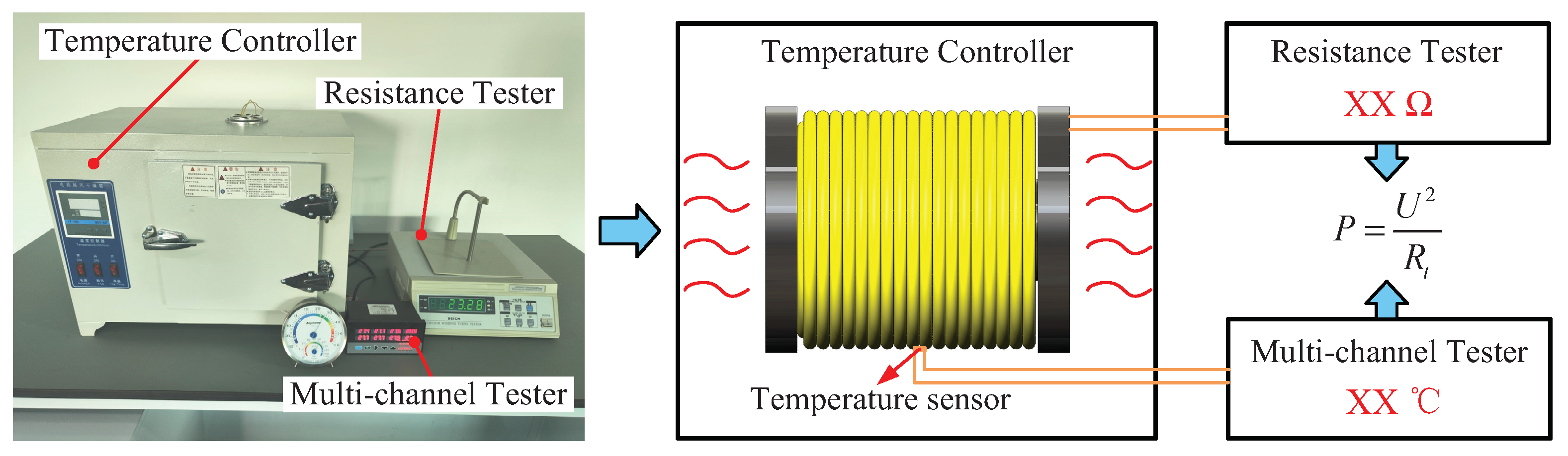
4. Testing the Power Consumption of Electromagnet Coil
4.1. Experimental System
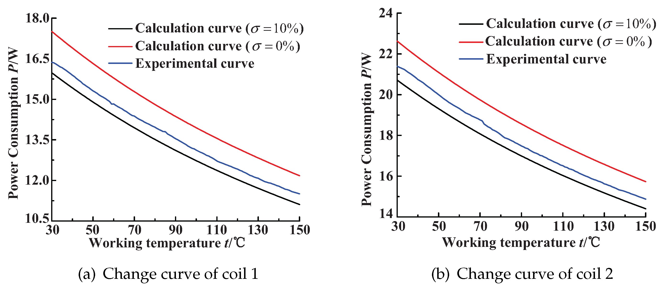
4.2. Experimental Results
5. Conclusions
Author Contributions
Funding
Data Availability Statement
Acknowledgments
Conflicts of Interest
Abbreviations
| FEM | Finite element method |
| HTS | High-temperature superconducting |
| TCV | Traction control valve |
| HSV | High-speed solenoid valve |
| BPNN | Back-propagation neural network |
References
- Li, Y.; Li, R.; Yang, J.; Yu, X.; Xu, J. Review of Recent Advances in the Drive Method of Hydraulic Control Valve. Processes 2023, 11, 2537. [Google Scholar] [CrossRef]
- Pate, K.; Azzam, I.; Breidi, F.; Marschand, J.R.; Lumkes, J.H. Digitalization of Radial Piston Pumps through Internal Mechanically Actuated Designs. Actuators 2023, 12, 425. [Google Scholar] [CrossRef]
- Yang, Q.; Wu, G.; Zhang, S. Smart Control of DCT Proportional Solenoid Valve Based on Data Mining. Int. J. Automot. Technol. 2024, 25, 37–46. [Google Scholar] [CrossRef]
- Crawford, C.B.; Straley, J.P. Improved prescription for winding an electromagnet. Rev. Sci. Instrum. 2021, 92, 124707. [Google Scholar] [CrossRef]
- Liao, Y.; Li, Z.; Yuan, H.; Feng, J.; Cui, H. Optimization of an intrinsically safe solenoid valve and the static and dynamic characteristics. Int. J. Appl. Electrom. 2019, 61, 111–122. [Google Scholar] [CrossRef]
- Wang, Z.; Yang, M.; Xiong, Q. Coil Temperature Rise and Structure Optimization in Electromagnetic Forming. Trans. China Electrotech. Soc. 2021, 36, 3891–3901. [Google Scholar]
- Yongbae, K.; Chansol, P.; Youngil, K. Optimal Design of Uni-Directional Linear Solenoid. In Proceedings of the 2022 6th International Conference on Electric Power Equipment-Switching Technology (ICEPE-ST), Seoul, Republic of Korea, 15–18 March 2022; pp. 376–379. [Google Scholar]
- Mukherjee, P.; Rao, V.V. Optimization of HTS Superconducting Solenoid Magnet Dimensions for Maximum Energy Density. J. Supercond. Nov. Magn. 2020, 33, 2649–2656. [Google Scholar] [CrossRef]
- Bhunia, U.; Saha, S.; Chakrabarti, A. Design optimization of superconducting magnetic energy storage coil. Phys. C 2014, 500, 25–32. [Google Scholar] [CrossRef]
- Cheng, Q.; Zhang, Z.; Xie, N. Power losses and dynamic response analysis of ultra-high speed solenoid injector within different driven strategies. Appl. Therm. Eng. 2015, 91, 611–621. [Google Scholar] [CrossRef]
- Xue, H.; Hu, B.; Fan, C.; Yang, H. Optimization and simulation of operating electromagnets in high-voltage switches based on Ansys-Maxwell. Electrotech. Appl. 2020, 39, 18–24. [Google Scholar]
- Lee, H.S.; Park, S.G.; Hong, M.P.; Lee, H.J.; Kim, Y.S. A Study on the Manufacture of Permanent Magnet Traction Control Valve for Electronic Stability Control in Electric Vehicles. Appl. Sci. 2021, 11, 7794. [Google Scholar] [CrossRef]
- Liu, C.; Wang, A.; Li, X.; Li, X. Thermal Load Model of a Proportional Solenoid Valve Based on Random Load Conditions. Sensors 2023, 23, 9474. [Google Scholar] [CrossRef] [PubMed]
- Xu, C.; Xie, F.; Fan, R.; Wei, R.; Tian, Z. Dynamic Characteristics Analysis of the High-Speed on/off Valve Considering Electromagnet Coil Configurations. J. Xi’an Jiaotong Univ. 2024, 58, 211–220. [Google Scholar]
- Raut, P.R.; Bahirat, H.J.; Atrey, M.D. Analytical Approach for Optimal HTS Solenoid Design. IEEE Trans. Appl. Supercond. 2021, 31, 1–9. [Google Scholar] [CrossRef]
- Hashemi, A.; Yazdanpanah Qaraei, P. Multi-coil electromagnets: An accurate magnetic equivalent circuit, cost, and energy management. Int. J. Numer. Model. 2021, 34, e2868. [Google Scholar] [CrossRef]
- Zhao, J.; Yue, P.; Grekhov, L.; Ma, X. Hold current effects on the power losses of high-speed solenoid valve for common-rail injector. Appl. Therm. Eng. 2018, 128, 1579–1587. [Google Scholar] [CrossRef]
- Yu, Z.; Yang, L.; Zhao, J.; Grekhov, L.; Liu, C. Research on Multi-Objective Optimization of High-Speed Solenoid Valve Drive Strategies under the Synergistic Effect of Dynamic Response and Energy Loss. Energies 2024, 17, 300. [Google Scholar] [CrossRef]
- Guo, J.; Zhang, X.; Zhang, X.; Jiang, J.; Jin, L.; Zhu, W. Study and Development on a Micro Proportional Electromagnet. Chin. Hydraul. Pneum. 2023, 47, 169–174. [Google Scholar]
- Song, Y.; Yang, L.; Chen, X.; Zhou, W.; Qiu, T.; Hao, Y.; Ai, C.; Kong, X. Optimization design of DC electromagnet coil considering the power consumption and cost. IEEJ Trans. Electr. Electron. Eng. 2024, 19, 1420–1428. [Google Scholar] [CrossRef]
- Lee, H.S.; Kim, Y.S. Design of Permanent Magnet Solenoid Valve for Electric Vehicle AVH. Int. J. Automot. Technol. 2023, 24, 1643–1653. [Google Scholar] [CrossRef]
- Yang, L.; Gao, T.; Du, X.; Zhai, F.; Lu, C.; Kong, X. Electromagnetic Characteristics Analysis and Structure Optimization of High-Speed Fuel Solenoid Valves. Machines 2022, 10, 964. [Google Scholar] [CrossRef]


| Parameter | Value | Parameter | Value |
|---|---|---|---|
| /mm | 0.4 | U/V | 20 |
| N | 2000 | /mm | 9.5 |
| 0.1 | /mm | 0.02 | |
| n | 70 | /· m | |
| / | / | 30 |
| Number | /mm | n | N | Parameter |
|---|---|---|---|---|
| 1 | 5 | 10 | 10 | = / = = 0 = 50 mm = · m |
| 2 | 5 | 10 | 20 | |
| 3 | 10 | 10 | 10 |
| Number | Scheme 1 | Scheme 2 | Scheme 3 |
|---|---|---|---|
| Relative deviation e | 0.54% | 0.46% | 0.78% |
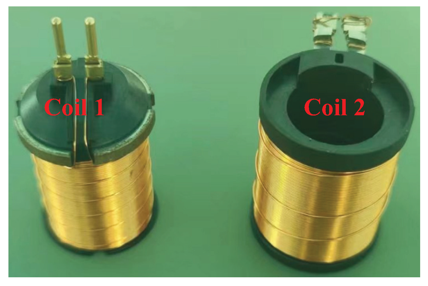
| Number | /mm | n | N | /· m | /mm | / | /mm |
|---|---|---|---|---|---|---|---|
| Coil 1 | 0.236 | 97 | 880 | 9.05 | 0.01975 | ||
| Coil 2 | 0.315 | 81 | 1057 | 9.6 | 0.02175 |
Disclaimer/Publisher’s Note: The statements, opinions and data contained in all publications are solely those of the individual author(s) and contributor(s) and not of MDPI and/or the editor(s). MDPI and/or the editor(s) disclaim responsibility for any injury to people or property resulting from any ideas, methods, instructions or products referred to in the content. |
© 2024 by the authors. Licensee MDPI, Basel, Switzerland. This article is an open access article distributed under the terms and conditions of the Creative Commons Attribution (CC BY) license (https://creativecommons.org/licenses/by/4.0/).
Share and Cite
Song, Y.; Shi, G.; Gu, C.; Cao, Z.; Ba, K.; Hao, Y.; Kong, X. An Improved Method for Calculating the Power Consumption of Electromagnet Coil. Machines 2024, 12, 602. https://doi.org/10.3390/machines12090602
Song Y, Shi G, Gu C, Cao Z, Ba K, Hao Y, Kong X. An Improved Method for Calculating the Power Consumption of Electromagnet Coil. Machines. 2024; 12(9):602. https://doi.org/10.3390/machines12090602
Chicago/Turabian StyleSong, Yanhe, Guozhao Shi, Chengze Gu, Zeyu Cao, Kaixian Ba, Yueyue Hao, and Xiangdong Kong. 2024. "An Improved Method for Calculating the Power Consumption of Electromagnet Coil" Machines 12, no. 9: 602. https://doi.org/10.3390/machines12090602
APA StyleSong, Y., Shi, G., Gu, C., Cao, Z., Ba, K., Hao, Y., & Kong, X. (2024). An Improved Method for Calculating the Power Consumption of Electromagnet Coil. Machines, 12(9), 602. https://doi.org/10.3390/machines12090602