Abstract
The efficiency of bevel and hypoid gears is, alongside load capacity, one of their most important design criteria. To consider the efficiency of bevel and hypoid gears during the development and design process, validated calculation methods based on experimental investigations are necessary. However, the isolated experimental investigation of the load-dependent power losses of bevel and hypoid gears has not been adequately investigated, as most of the experimental investigations consider the complete gearbox. This paper presents a test rig that allows for the experimental investigation of the efficiency of bevel and hypoid gears with a measurement uncertainty of the efficiency of according to the Guide to the Expression of Uncertainty in Measurement (GUM). Using the developed test rig, experimental investigations on the efficiency behavior of bevel and hypoid gears regarding the influence of the axial offset, driving direction, and microgeometry are carried out for different operating points varying in circumferential speed and load. This paper discusses the methodology and the first experimental results of a study on the efficiency of bevel and hypoid gears in detail.
1. Motivation and Introduction
In 2015, the United Nations addressed the global challenges facing the planet through the formulation of the 17 Sustainable Development Goals. Considering the increasing challenges of climate change and its consequences in the present time, it is unquestionably essential to take concerted action, especially in alignment with the UN Sustainable Development Goals. Therefore, the reduction of greenhouse gases (GHGs) and, in particular, CO2, as a primary driver of climate change, must be taken into account by gear engineers within their research and development activities.
In this context, one priority topic is the increase in the efficiency of powertrains. For the optimization of powertrains, it is necessary to concentrate on each component separately. Bevel and hypoid gears are widely used in applications where the rotary motion needs to be transmitted between non-parallel axes. Besides axle drives within the automotive section, bevel and hypoid gears are used in marine applications, helicopter drives, and industrial applications. Due to the high amount of sliding movement and subsequent heat dissipation within the tooth contact of bevel and hypoid gears, there is high potential to increase the efficiency by considering it in the design process of bevel and hypoid gears in addition to the load carrying capacity. There are various calculation approaches regarding the estimation of the efficiency behavior of bevel and hypoid gears but currently there is no standardized calculation approach to define the load-dependent and independent gear power losses. For the validation of calculation approaches in general, experimental investigations are used. The available measurement results on the efficiency of bevel and hypoid gears are mostly based on whole gearboxes, which impedes the consideration of the gear power losses due to parallel considerations of other mechanical components like bearings and sealings. Therefore, the available measurement results do not fulfill the requirement for the accuracy of the measurement resolution to reflect small differences in the efficiency of bevel and hypoid gears.
Within this paper, a new test rig for the experimental investigation of the efficiency of bevel and hypoid gears is presented. The test rig allows for the measurement of the gear power losses of bevel and hypoid gears with a suitable measurement resolution to validate state-of-the-art calculation approaches of the gear power losses of bevel and hypoid gears. Experimental investigations carried out by one of the authors with the presented test rig [] are discussed regarding the influence of the axial offset, the driving direction, and the microgeometry on the efficiency of bevel and hypoid gears.
2. State of the Art
The total power losses PV of a gearbox are composed of the partial losses generated in the individual components of the gearbox. Typical components contributing to the total power losses are gear tooth mesh losses PVZ, bearing losses PVL, sealing losses PVD, and other losses PVX. Additionally, the losses can be subdivided into load-dependent and load-independent losses []. The total power losses PV of a gearbox can be summarized as follows:
| W | load-dependent gear tooth mesh losses | W | load-independent bearing losses | ||
| W | load-independent gear power losses | W | sealing losses | ||
| W | load-dependent bearing losses | W | other losses |
In the following, the power losses contributing to the total power losses and the state-of-the-art calculation methods for the gear tooth mesh losses of bevel and hypoid gears will be discussed. Then, the state-of-the-art test rig concepts and measurement methods for gear power losses in general and specifically for bevel and hypoid gears will be presented.
The load-dependent gear tooth mesh losses occur during the meshing of two tooth flanks under load due to rolling and sliding friction. According to Niemann [], the losses due to rolling friction can be neglected, and therefore, the load-dependent gear tooth mesh losses can be calculated based on Coulomb’s law. Wirth [] describes a methodology for determining gear power loss based on the results from a tooth contact analysis using BECAL []. By using an LTCA, Wirth [] considers the changing load and velocity conditions along the path of contact. For the local coefficient of friction, Wirth [] uses an approach by Klein [], which allows for a local examination of the individual contact points on the gears. The total load-dependent gear power losses can be determined by summing up all locally occurring losses. A comparable approach to improving the efficiency of bevel and hypoid gears using an LTCA and a semi-empirical formulation of the friction coefficient is given by Grabovic et al. [,]. A combined calculation approach using an LTCA and a subsequent EHD simulation for predicting the gear power losses in bevel and hypoid gears is given by Kolivand [], Simon [], Mohammadpour et al. [,,], and Ding et al. []. In addition to the high accuracy calculation methods using an LTCA, the efficiency of bevel and hypoid gears can be calculated with simplified approaches mainly using macrogeometry data of the gear set and operation conditions. Simplified calculation methods regarding the load-dependent gear tooth mesh losses of bevel and hypoid gears are given by Wech [] and also within the ISO/TS 1300-20:2021 [] and ISO/TR 14179-1:2001 [].
Load-independent gear power losses can be grouped into hydraulic and windage losses []. The main influencing parameters are speed, circumferential speed, temperature of the lubricant, and the oil level []. Empirical calculation approaches for the hydraulic losses of gears are given by Mauz and Walter [,]. Simulative investigations based on computational fluid dynamic (CFD) programs are provided by [,,]. Concli validates theoretical calculation approaches with experimental investigations of spur gears []. In [], Seetharman et al. present a calculation model based on fluid mechanics for calculating idle losses, validated in [] based on results from extensive experimental investigations that varied speed, oil level, and fundamental gear geometry parameters. Experimental investigations on the load-independent gear power losses on bevel gears were performed by Jeon [] using a practical axle gearbox as well as by Quiban et al. [].
Load-dependent and load-independent bearing losses can be calculated using empirical calculation approaches provided by the manufacturer, like SKF [,] or INA []. These calculation approaches are widely used within the industry and are similar to the calculation method given in ISO/TR 14179-2:2001 []. Calculation methods with higher accuracy and consideration of the whole shaft-bearing system and housing stiffness are described in [,]. Yilmaz [] describes experimental investigations of the bearing losses.
Simplified calculation approaches for the sealing losses are given in ISO/TR 14179-1:2001 []. For non-contact type sealings, power losses can be assumed to be negligible []. Other losses PVX result from disc clutches, synchronizers, and other phenomena like churning losses of the differential cage [,]. According to [], these losses are typically carried out by power loss measurements using the complete gearbox.
Various methods are currently used in industry and research to experimentally determine gearbox losses; this can be done either by measuring the power loss (direct determination of the degree of loss) or by measuring the power difference (indirect determination of the degree of loss). Methods of direct power loss measurement of gearboxes typically involve the measurements at a back-to-back test rig using a pendulum gearbox suspension or the calorimetry method []. These main methods of measurement are summarized in Figure 1.
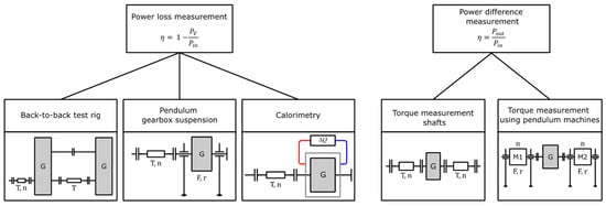
Figure 1.
Measuring principles for efficiency determination according to Goebbelet et al. [].
The mechanical back-to-back principle is used in various investigations regarding the efficiency of spur gears [,] as well as for high-speed applications []. Wech [] used the mechanical back-to-back principle for his extensive experimental investigations of the efficiency of bevel gears. The test rig setup is based on four identical bevel-helical gearbox combinations. The spur gears are used to operate all bevel gearboxes under similar operating conditions with regard to loaded flank and driving direction. Detailed knowledge of the losses occurring in addition to the bevel gear power losses, such as bearing and spur gear power losses, is required to determine the gearing loss performance of the investigated bevel and hypoid gearings.
According to Goebbelet et al. [], measuring the power loss of gearboxes using a pendulum gearbox suspension is only suitable for selected gearbox systems. This measurement method is described in [] for experimental investigations at high speeds.
The calorimetry method is based on the fact that power losses due to friction are completely and irreversible transformed into heat []. The applicability of this method for multi-megawatt gearboxes of wind turbines was proven by Pagitsch et al. [], although the time required to achieve the necessary thermal steady-state condition is relatively high.
When using a power difference measurement, the input and output power of the tested gearbox are measured. According to Goebbelet et al. [], two different methods of torque measurement can be distinguished in power difference measurements. One standard method is the power difference measurement using a pendulum machine. The second standard method for power difference measurement is torque measurement using torque measurement shafts. An advantage compared to the use of pendulum machines is the variable design of the measuring area, which allows the use of additional components with losses, such as support bearings and transmission gears, without affecting the measuring accuracy. According to Homann [], power difference measurement using torque measuring shafts is currently the most common method of power difference measurement and, at the same time, the most common method for experimental efficiency determination. An electrical tensed test rig for bevel gears using two electrical machines is described by Leighton [], which is capable of investigating the efficiency of the gearing system. Strama-MPS Maschinenbau GmbH & Co. KG, Straubing, Germany [] offers a bevel gear test rig based on the principle of a CNC machine, which enables the measurement of efficiency and the determination of load carrying capacity and wear.
3. Objective and Approach
To define the efficiency of bevel and hypoid gears during the development process, methods for calculating the efficiency of bevel and hypoid gears are needed. Experimental investigations are generally used to validate these calculation methods. However, the available measurement results on the efficiency of bevel and hypoid gears are predominantly based on the entire gearboxes, which complicates the isolation of gear power losses, as the measurements also account for other mechanical components. This highlights the need for a test rig concept and a test rig for precisely measuring the gear efficiency of bevel and hypoid gears. This test rig allows subsequent researchers to develop and validate a standardized calculation approach to the efficiency of bevel and hypoid gears, which is currently not present in the state-of-the-art.
The objective of this paper is the development of a test rig for the investigation of the efficiency of bevel and hypoid gears. By using this test rig, experimental investigations of the efficiency behavior of bevel and hypoid gearboxes with regard to the axial offset, the driving direction, and the microgeometry are carried out for varying circumferential speeds and loads.
4. Test Rig Concept
The bevel gear efficiency test rig designed in the underlying research project [] uses two electrical machines based on the electrical tensed concept. To capture the torque loss TV of the complete gearbox, the input and output torque, Tin,out, and the input and output speed of the gearbox, are precisely measured using optical angular measurement systems. The total gearbox torque loss can be calculated using Equation (2).
| Nm | total gearbox torque loss | Nm | output torque | ||
| Nm | input torque | - | gear ratio |
To determine the load-independent gearbox torque loss, depending on the driving direction, the measuring shaft at the pinion or wheel shaft is removed, and in this way, the drag torque caused by the gearbox is measured. Within the drag torque, the load-independent gear torque loss, the load-independent bearing torque loss, and the sealing torque loss for specific operational conditions are included. The load-dependent bearing losses for specific operational conditions and no-load conditions can be evaluated experimentally for each bearing using the FZG bearing power loss test rig [] and are checked for consistency with the calculation approach by SKF []. By doing so, the load-dependent gear torque loss TVZP can be calculated using Equation (3).
| Nm | load-dependent gear torque loss | Nm | drag torque of gearbox (load-independent) | ||
| Nm | total gearbox torque loss | Nm | load-dependent bearing torque loss of all bearings of the gearbox |
The schematic structure of the bevel gear efficiency test rig is depicted in Figure 2.
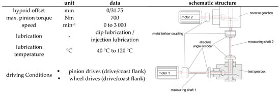
Figure 2.
Schematic structure of bevel gear efficiency test rig [].
4.1. Mechanical Structure
The bevel gear efficiency test rig consists of a test gearbox, a reverse gearbox, and two identical electric motors. The load on the test gearbox is applied by one of the two electric motors. Depending on the driving direction to be examined in the test gearbox, one of the two motors acts as a brake. The individual test rig components are connected via shafts and metal bellows couplings. The test gearbox is connected to the other test rig components through torsional flexible measuring shafts. The reverse gearbox is used for space reasons. Additionally, due to the identical gear ratio of the test gearbox and the reverse gearbox, the entire characteristic curve of the two identical electric motors can be utilized. The bearing arrangement of the pinion and the wheel of the test gear set is designed as a fixed-floating bearing arrangement. Four-point contact bearings are used as axial bearings, and cylindrical roller bearings are used for radial restraint. Applying a fixed-floating bearing arrangement, compared to a preloaded and adjusted bearing arrangement with tapered roller bearings, allows for a clear assignment and, therefore, a reproducible determination of the loads relevant for bearing losses on each respective bearing. The pinion and wheel are in an axial direction and are continuously adjustable; therefore, a precise and reproducible configuration of the contact pattern and backlash is given. The test gear set is dip-lubricated, and the gearbox bearings are supplied with a defined oil flow from an external oil unit to ensure lubrication and heat transfer. In addition, by having a defined oil flow from an external oil unit, the comparability of the lubrication conditions of the bearings between the bevel gear efficiency test rig and the FZG bearing power loss test rig is given. The oil level in the gearbox housing is kept constant using a siphon. The oil unit allows for the adjustment of a defined oil temperature in the oil sump through cooling and heating. The shafts are sealed using radial shaft seals.
4.2. Measuring Equipment
To measure the torques applied to the input and output shafts, the elastic deformation of the shafts under load is measured. For this purpose, an ultra-high accuracy absolute angle encoder of the REXA type by Renishaw plc, Wotton-under-Edge, UK is attached to each end of the input and output shaft. The absolute position is determined at each encoder using two readheads of the RESOLUTE type by Renishaw plc. Using two readheads for each encoder allows for the compensation of errors arising from eccentricities of the shaft. According to Renishaw plc. [], this method enables the determination of the angular position with a maximum measurement uncertainty of under the condition that the encoder and readheads are correctly aligned on the shaft and with each other.
The torque measurement system on the bevel gear efficiency test rig is calibrated in accordance with DIN 51309:2022 [], based on the lever–mass system. Therefore, a particular calibration routine was developed, including three ascending and descending load phases up to the maximum test load interrupted by relaxation phases after each load step to determine short-term creep. The measuring shafts are calibrated in the same installation position in the test rig at four rotational positions, each offset by .
Data processing takes place on an evaluation computer, with communication and data processing facilitated by a CompactRIO controller from National Instruments Corp, Austin, USA with BiSS Interface modules from the manufacturer S.E.A. Datentechnik GmbH, Troisdorf, Germany. The temperature measurement in the oil sump is carried out using a Pt100 temperature sensor of accuracy class A according to DIN EN IEC 60751:2023 []. The temperature sensor can be adjusted depending on the oil level to ensure sufficient immersion depth.
4.3. Measurement Uncertainty
As part of the research project [], an uncertainty analysis following the Guide to the Expression of Uncertainty in Measurement (GUM) [] was conducted to investigate the measurement uncertainty associated with the parameters captured on the bevel gear efficiency test rig. Therefore, the software GUM-Workbench (version 2.4) [] and the procedure according to Sommer [] were used.
To investigate the measurement uncertainties occurring on the bevel gear efficiency test rig, the uncertainty of the calibration of the measuring shafts is determined in the first step, and the uncertainty of the efficiency determination is calculated on this basis. As part of the calibration, the calibration factor k, which describes the ratio of the actual calibration torque TCal to the theoretically determined torque TMeas,th, is determined. The torque applied to the measuring shaft is calculated by multiplying the theoretically measured torque Tmess,th by the calibration factor k. To determine the efficiency, the measured output torque TMess,out and the input torque TMess,in are set in relation to each other. Equation (4) thus represents the system equation for the uncertainty analysis carried out according to GUM [] for the case of a gear ratio of .
| - | Efficiency | Nm | Measured torque | ||
| rad | Measured torsion angle | rad | Measured torsion angle at calibration torque | ||
| kg | Mass of the calibration weights | kg | Mass of the lever | ||
| m | Length of the lever arm | m | Distance of the lever’s center of gravity from the center of the axis | ||
| ° | Angle between the reference axis of the lever and the horizontal | ° | Angle between the reference axis of the lever and the normal to the measuring shaft |
Since the measurement uncertainty is reduced by a factor of for gear ratios greater than , the uncertainty analysis shown here represents the worst case. Table 1 summarizes the expanded measurement uncertainties for the efficiency measured on the bevel gear efficiency test rig with a coverage probability of 95% for three load cases (20%, 60%, 100%) and exemplary efficiency values.

Table 1.
Measurement uncertainty of the bevel gear efficiency test rig.
The expected measurement uncertainty of the efficiency is within a range of throughout the entire operating range of the test rig. The developed measurement technology thus allows the resolution of even slight differences in efficiency. It is, therefore, suitable for application in the context of the experimental investigations of the present study.
5. Methodology
5.1. Objects of Investigations
Within the experimental investigations, three variants of bevel and hypoid test gear sets are examined in terms of their efficiency behavior. The macrogeometries of both hypoid test gear sets are identical; they differ only in the design of the microgeometry. The basic geometry data of both macrogeometries are given in Table 2. The material of these test gear sets is 18CrNiMo7-6.
Table 2.
Basic geometry data of the gear set variants G0 and G31.75.
The hypoid test gear set variant G31.75 was designed with two different microgeometries. The test gear set variants G31.75kl and G31.75gr were designed by Klein [,] to investigate the influence of the Ease-Off design on the local flank pressure distribution. Therefore, variant G31.75gr was designed with conventional Ease-Off, meaning normal crowning values resulting in a large contact pattern and thus in lower contact stresses for the same input torque in comparison to variant G31.75kl. The G31.75kl test gear variant is designed with high crowning values, resulting in a small contact pattern. The values for lengthwise (LB) and profile crowning (HB), as well as the ease-off design and the load-free contact pattern for the drive side, calculated with the program Klingelnberg Integrated Manufacturing of Spiral Bevel Gears (KIMoS 5) [], is given for the test gear variants in Figure 3. Exemplary contact patterns under load and load distribution for a pinion load of T1 = 300 Nm calculated with KIMoS 5 [] are also given in Figure 3.
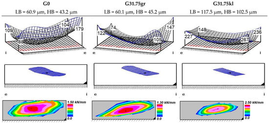
Figure 3.
Ease-Off design and load-free contact pattern of test gear variants (drive side).
The quality of all used test gear sets was investigated using a 3D coordinate measurement center Klingelnberg P40 by Klingelnberg GmbH, Hückeswagen, Germany. The total cumulative pitch deviation FP was measured and classified according to DIN 3965-1:1986 []. The flank roughness was measured using the 3D coordinate measurement center at three teeth and on each tooth at three separate measuring paths vertical to the pitch angle. The results of these measurements are given in Table 3. Additionally, the flank topography of the test gear sets was measured, resulting in only minor, hence negligible, deviations from the nominal microgeometry.
Table 3.
Quality and flank roughness of test gear variants G0, G31.75gr and G31.75kl.
5.2. Considered Lubricant
For the experimental investigation, the reference oil FVA3 with an additive proportion of 4% Anglamol 99 (FVA3 A for short) was used. It is a mineral-based oil with a kinematic viscosity of and . The density is [].
5.3. Experimental Procedure
For the experimental investigations of the gear power losses, the test rig, described in Section 4, was used. The test gear set was lubricated by dip lubrication; the oil level was kept constant on the level of the pinion axle and controlled to an oil temperature of . For each experimental investigation, test gear sets with run-in flank surfaces, using the same running-in procedure, were used. For each test run, the load was kept constant, and the circumferential speed was variated in ascending or descending order. After all circumferential speed levels had been investigated, the next load was set, and the procedure was repeated. After completing the test runs under load, the load-independent losses were investigated using no load. To ensure a steady-state operating condition, each test point was held constant for 15 min, though only the last 5 min were taken into account for the evaluation. For the examination of repeat accuracy, at least one repeat test was performed for each test point. The drive direction for all experimental investigations was pinion drives wheel on the drive side, except for the investigation of the driving direction where the operation condition wheel drives pinion on the drive side was applied.
For the different operating points, the circumferential speed was varied according to Table 4, and the pinion torque was varied according to Table 5. The varied pinion torque results in varied flank pressures , which are calculated using an LTCA [,] (see Table 5). The LTCA program [,] uses a manufacturing simulation to model the actual tooth, performs a tooth contact analysis using, in this case, the Boundary Elements Method (BEM), and is widely used in both industry and research for the analysis of bevel and hypoid gears.
Table 4.
Variation of circumferential speed of operation points.
Table 5.
Variation of pinion torque of operating points.
6. Results and Discussion
In the following, the measurement results for the torque loss TV of the experimental investigations on the bevel gear efficiency test rig are presented in detail, whereby the measured values describe the arithmetic mean of the measured data for each load case. As a result, for each torque stage, represented by the pinion torque T1, the measured torque loss TV over the circumferential speed vt is shown. Initial and repeat tests are entered to document the repeat accuracy. The lines between the test points represent the mean values.
6.1. Influence of Axial Offset on the Efficiency of Bevel and Hypoid Gears
Figure 4 shows the measured torque losses TV of the overall test gearbox for the test gear variant G0 at the oil sump temperature ϑoil = 90 °C using the oil FVA3 A as a solid line. The entire tooth width of the ring gear is immersed in the oil sump. The results show fundamental trends in the loss behavior of the gearbox. The gearbox loss torque TV at the lowest load increases slightly with increasing circumferential speed vt. At the highest load, there is a slight increase in the gearbox loss torque with increasing circumferential speed vt. The lowest loss torques TV occur in the no-load operating state. These increase as the load increases. The no-load loss torque TV0 exhibits a behavior close to linear over the entire speed range and increases with increasing circumferential speed vt. At the lowest measured load of T1 = 100 Nm, the no-load losses represent the decisive share of the total gearbox losses. At the higher loads investigated, the load-related losses TVL make the most significant contribution to the total gearbox losses.
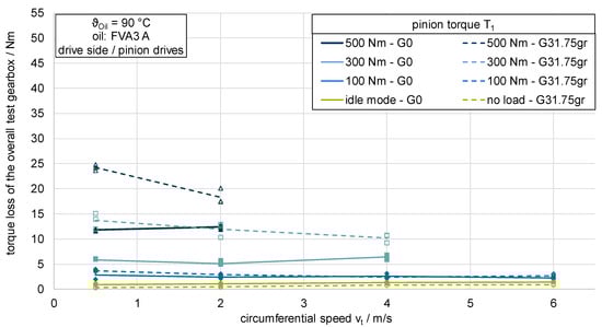
Figure 4.
Influence of axial offset on the efficiency of bevel and hypoid gears.
The results for the test gear variant G31.75gr, which shows a hypoid offset of a = 31.75 mm and a similar microgeometry to the G0 variant, are shown as a dashed line. The ring gear is also immersed in the oil sump over its entire tooth width. Compared to the test gear variant G0, the losses at the same load are significantly larger in the higher load stages. In contrast to test gear variant G0, these losses decrease as the circumferential speed vt increases. At the lowest investigated load. , the measured losses show a similar level and a decreasing behavior with increasing circumferential speed vt. The no-load losses of the test gear variant G31.75gr are slightly lower than those of variant G0 and show a slightly increasing curve.
According to the current state of knowledge, the difference in the losses of the two gear variants can be explained by the additional amount of sliding in the longitudinal direction of the teeth in gearing with hypoid offset compared to non-offset bevel gears. This additional amount of sliding means, among other things, that there is no pure rolling on the pitch cone, as is the case with non-offset bevel gears and cylindrical gears, but that sliding in the longitudinal direction of the teeth also occurs in this area. The effect of higher power losses for hypoid gears due to the amount of sliding increases for high torques as the contact pattern enlarges, and therefore, the amount of sliding within the gear mesh increases. This can be seen in Figure 4, where the difference in torque loss of the overall gearbox between the non-offset bevel gear and the hypoid variant increases for higher torques.
6.2. Influence of Microgeometry on the Efficiency of Bevel and Hypoid Gears
Figure 5 shows the measured torque losses TV of the overall test gearbox for the test gear variants G31.75gr and G31.75kl. The two test gear variants differ in their microgeometry design, whereby the G31.75kl variant is characterized by larger crowning and, therefore, a smaller contact pattern than the G31.75gr variant. The oil sump temperature is 90 °C, and the entire tooth width of the ring gear is immersed in the oil sump. As expected, the measured no-load losses of the two variants match very well. Therefore, the microgeometry of the gearing has no measurable influence on the no-load losses of the gearbox with otherwise identical gear parameters. The curves of the measured loss torque of the test gear variant G31.75kl show smaller amounts compared to the G31.75gr variant, which clearly indicates that this deviation is load-dependent and increases with increasing load. The loss torque curves as a function of the circumferential speed vt show similar trends and tendencies for both microgeometry variants and decrease with increasing speed.
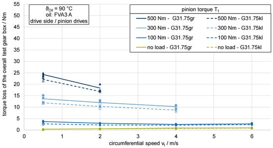
Figure 5.
Influence of microgeometry on the efficiency of bevel and hypoid gears.
Due to the different microgeometry designs of the test gear variants G31.75gr and G31.75kl, different crowning and, therefore, different contact patterns result. Since the contact pattern sizes of the two gear variants differ not only in the unloaded state, as shown in Figure 3. In the Ease-Off design and load-free contact pattern of test gear variants (drive side), but also in the loaded state, there is a difference in the flank pressure. On the other hand, areas of the flank are in contact with different sliding velocities. As the efficiency behavior depends on the contact stress and the occurring sliding velocity, the two gear variants show different loss behavior.
6.3. Influence of Driving Direction on the Efficiency of Bevel and Hypoid Gears
Figure 6 compares the measured torque losses TV of the G31.75gr variant in the operating mode “pinion drives” with the losses in operating mode “wheel drives”. The oil sump temperature ϑoil is 90 °C, and the entire tooth width of the ring gear is immersed in the oil sump. Compared to an operation with a driving pinion, significantly higher losses occur with a driving wheel at all loads and speeds investigated. The curves as a function of the circumferential speed vt show similar tendencies for both operating conditions and decrease with increasing speed. The no-load losses with a driving wheel are slightly lower than with a driving pinion.
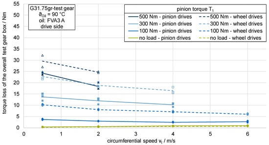
Figure 6.
Influence of driving direction on the efficiency of bevel and hypoid gears.
According to Wech [], the drive direction-dependent loss behavior can be explained by the change in the sliding movement of the tooth flanks. Due to the positive profile shift of the test gears, the addendum of the pinion and wheel are different. When the gear set is operated with a driving wheel, larger areas of the tooth flank are subjected to negative specific sliding than when the pinion is driving. According to Jurkschat [], there are higher gear friction coefficients in the case of negative specific sliding, which leads to greater load-dependent gear power losses. Michaelis [] identifies the poorer lubrication conditions at the start of meshing and, therefore, in the areas of highest sliding velocities when the gear is driving, in addition to the larger flank areas subjected to negative specific sliding, as the cause of higher losses with a driving wheel. The changing rotation direction for the different operation conditions may also influence the load-dependent bearing losses of the whole gearbox.
7. Summary and Outlook
The consideration of the efficiency in mechanical transmissions moves into focus due to increasing challenges caused by climate change and its consequences in the present time. Therefore, calculation methods are necessary to consider efficiency in the early stages of the design process of bevel and hypoid gears. For the validation of such calculation methods, highly accurate experimental results are required. Thus, this paper’s objective is to present a test rig concept for the experimental investigation of the efficiency of bevel and hypoid gears and, subsequently, the experimental investigation of several influencing factors on the efficiency of bevel and hypoid gear by using the newly developed test rig.
The newly developed bevel gear efficiency test rig allows for the highly accurate measurement of the efficiency of bevel and hypoid gears at different operational conditions with a measuring uncertainty of according to GUM []. With a complementary experimental investigation of the load-dependent bearing losses and the measurement of the idle losses of the gearbox, an accurate value of the load-dependent gear tooth mesh losses can be obtained.
In experimental investigations using the newly developed bevel gear efficiency test rig, the influences of the axial offset, the microgeometry, and the driving direction on the efficiency were evaluated for different operational conditions. In all experimental tests, the measured efficiency of the whole gearbox is within a reasonable section for bevel and hypoid gears between 93.5% and 97.5%. The influence of speed and load on the efficiency of the test gear set could be clearly detected for each of the investigated influencing parameters. The results show that, according to the state of knowledge, the higher amount of sliding due to the axial offset leads to a decrease in the efficiency of the gearbox. Additionally, a larger contact pattern size leads to higher torque losses, shown by the experimental results for a range of input torques and speeds. A further experimental study investigated the influence of the driving direction on the efficiency level of hypoid gears. The results show that, according to the state-of-the-art, the driving condition “wheel drives pinion” leads to higher losses than “pinion drives wheel”.
The next step is to evaluate the bearing losses for the respective operational conditions using the test rig concept by Yilmaz []. The calculation of the load-dependent gear tooth mesh losses for the bevel and hypoid gears and the use of these results for the validation of calculation methods is subject to further studies.
Author Contributions
Conceptualization, L.C. and J.P.; methodology, L.C. and J.P.; software, J.P.; validation, J.P. and M.W.; investigation, J.P., L.C. and M.W.; writing—original draft preparation, L.C., J.P. and M.W.; writing—review and editing, J.P. and K.S.; visualization, L.C., M.W. and J.P.; supervision, J.P. and K.S.; project administration, J.P.; funding acquisition, K.S. All authors have read and agreed to the published version of the manuscript.
Funding
The research project (IGF No. 19880 N; FVA 821 I) was conducted with the kind support of the FVA (Forschungsvereinigung Antriebstechnik e.V.) research association. The project was sponsored by the German Federal Ministry of Economics and Technology (BMWi) through the AiF (Arbeitsgemeinschaft industrieller Forschungsvereinigungen) in the course of a program for the support of collective industrial research (IGF) as a result of a decision by the German Bundestag.
Data Availability Statement
Data are contained within the article.
Conflicts of Interest
The authors declare no conflicts of interest.
References
- Pellkofer, J.; Hein, M.; Stahl, K. IGF-Nr. 19880 N—FVA 821 I: Kegelrad- und Hypoideffizienz: Berechnungsverfahren zur Vorhersage der Lastabhängigen Verzahnungsverluste von Kegelrad- und Hypoidgetrieben Basierend auf Hochgenauen Verlustmomentmessungen; 2022 Heft 1503; Forschungsvereinigung Antriebstechnik e.V. (FVA): Frankfurt/Main, Germany, 2022. [Google Scholar]
- Niemann, G.; Winter, H. Maschinenelemente: Band 2: Getriebe Allgemein, Zahnradgetriebe—Grundlagen, Stirnradgetriebe. Zweite, Völlig Neubearbeitete Auflage; Springer: Berlin/Heidelberg, Germany, 2003. [Google Scholar]
- Wirth, C.; Thomas, J. Local efficiency grade of bevel and hypoid gears: Determination of gear efficiency by means of loaded TCA. In Proceedings of the International Conference on Gears, Munich, Germany, 5–7 October 2015; VDI Verlag: Düsseldorf, Germany, 2015; pp. 105–114. [Google Scholar]
- Mieth, F. FVA 223 XX CAD2BECAL: Numerische Beanspruchungsberechnung an CAD-Modellen in BECAL; 2022 Heft 1519; Forschungsvereinigung Antriebstechnik e.V. (FVA): Frankfurt/Main, Germany, 2022. [Google Scholar]
- Klein, M. Zur Fresstragfähigkeit von Kegelrad- und Hypoidgetrieben. Ph.D. Thesis, Lehrstuhl für Maschinenelemente, Technische Universität München, München, Germany, 27 February 2012. [Google Scholar]
- Grabovic, E.; Artoni, A.; Gabiccini, M.; Ciulli, E. Exploration of trade-offs between NVH and efficiency in bevel gear design. Forsch Ingenieurwes 2023, 87, 933–947. [Google Scholar] [CrossRef]
- Grabovic, E.; Artoni, A.; Gabiccini, M.; Guiggiani, M.; Mattei, L.; Di Puccio, F.; Ciulli, E. Friction-Induced Efficiency Losses and Wear Evolution in Hypoid Gears. Machines 2022, 10, 748. [Google Scholar] [CrossRef]
- Kolivand, M.; Li, S.; Kahraman, A. Prediction of mechanical gear mesh efficiency of hypoid gear pairs. Mech. Mach. Theory 2010, 45, 1568–1582. [Google Scholar] [CrossRef]
- Simon, V. Improvements in the mixed elastohydrodynamic lubrication and in the efficiency of hypoid gears. Proc. Inst. Mech. Eng. Part J J. Eng. Tribol. 2020, 234, 795–810. [Google Scholar] [CrossRef]
- Mohammadpour, M.; Rahnejat, H.; Theodossiades, S. Elastohydrodynamics of Hypoid Gears in Axle Whine Conditions. In Elastohydrodynamics of Hypoid Gears in Axle Whine Conditions; SAE International: Warrendale, PA, USA, 2012. [Google Scholar]
- Mohammadpour, M.; Theodossiades, S.; Rahnejat, H.; Saunders, T. Non-Newtonian mixed elastohydrodynamics of differential hypoid gears at high loads. Meccanica 2014, 49, 1115–1138. [Google Scholar] [CrossRef]
- Mohammadpour, M.; Theodossiades, S.; Rahnejat, H. Elastohydrodynamic lubrication of hypoid gear pairs at high loads. Proc. Inst. Mech. Eng. Part J J. Eng. Tribol. 2012, 226, 183–198. [Google Scholar] [CrossRef]
- Ding, H.; Li, H.; Chen, S.; Shi, Y.; Wang, Y.; Rong, K.; Lu, R. Energy loss and mechanical efficiency forecasting model for aero-engine bevel gear power transmission. Int. J. Mech. Sci. 2022, 231, 107569. [Google Scholar] [CrossRef]
- Wech, L. Untersuchungen zum Wirkungsgrad von Kegelrad- und Hypoidgetrieben. Ph.D. Thesis, Institut für Konstruktion, Technische Universität München, München, Germany, 7 July 1987. [Google Scholar]
- ISO/TS 10300-20:2021; Calculation of Load Capacity of Bevel Gears: Part 20: Calculation of Scuffing Load Capacity—Flash Temperature Method. ISO International Organization for Standardization: London, UK, 2021.
- ISO/TR 14179-1:2001; Gears—Thermal Capacity: Part 1: Rating Gear Drives with Thermal Equilibrium at 95 °C Sump Temperature. ISO International Organization for Standardization: London, UK, 2001.
- Geiger, J. Wirkungsgrad und Wärmehaushalt von Zahnradgetrieben bei Instationären Betriebszuständen. Ph.D. Thesis, Lehrstuhl für Maschinenelemente, Technische Universität München, München, Germany, 2014. [Google Scholar]
- Mauz, J. Hydraulische Verluste bei Tauch- und Einspritzschmierung von Zahnradgetrieben. Ph.D. Thesis, Universität Stuttgart, Stuttgart, Germany, 1985. [Google Scholar]
- Walter, P. Anwendungsgrenzen für die Tauchschmierung von Zahnradgetrieben. Ph.D. Thesis, Universität Stuttgart, Stuttgart, Germany, 1982. [Google Scholar]
- Liu, H.; Link, F.; Lohner, T.; Stahl, K. Computational fluid dynamics simulation of geared transmissions with injection lubrication. Proc. Inst. Mech. Eng. Part C J. Mech. Eng. Sci. 2019, 233, 7412–7422. [Google Scholar] [CrossRef]
- Liu, H.; Jurkschat, T.; Lohner, T.; Stahl, K. Detailed Investigations on the Oil Flow in Dip-Lubricated Gearboxes by the Finite Volume CFD Method. Lubricants 2018, 6, 47. [Google Scholar] [CrossRef]
- Gorla, C.; Concli, F.; Stahl, K.; Höhn, B.R.; Klaus, M.; Schultheiß, H.; Stemplinger, J.P. CFD Simulations of Splash Losses of a Gearbox. Adv. Tribol. 2012, 2012, 616923. [Google Scholar] [CrossRef]
- Concli, F.; Gorla, C.; Stahl, K.; Höhn, B.R.; Michaelis, K.; Schultheiß, H.; Stemplinger, J.P. Load Independent Power Losses of Ordinary Gears: Numerical and Experimental Analysis. In Proceedings of the Politecnico di Torino (Hg.) 2013—5th World Tribology Congress, Torino, Italy, 8–13 September 2013. [Google Scholar]
- Seetharaman, S.; Kahraman, A. Load-Independent Spin Power Losses of a Spur Gear Pair: Model Formulation. J. Tribol. 2009, 131, 022201. [Google Scholar] [CrossRef]
- Seetharaman, S.; Kahraman, A.; Moorhead, M.D.; Petry-Johnson, T.T. Oil Churning Power Losses of a Gear Pair: Experiments and Model Validation. J. Tribol. 2009, 131, 022202. [Google Scholar] [CrossRef]
- Jeon, S.I. Improving Efficiency in Drive Lines: An Experimental Study on Churning Losses in Hypoid Axle. Ph.D. Thesis, Imperial College London, London, UK, 2010. [Google Scholar]
- Quiban, R.; Changenet, C.; Marchesse, Y.; Ville, F.; Belmonte, J. Churning losses of spiral bevel gears at high rotational speed. Proc. Inst. Mech. Eng. Part J J. Eng. Tribol. 2020, 234, 172–182. [Google Scholar] [CrossRef]
- SKF Gruppe. SKF Wälzlagerkatalog; SKF: Gothenburg, Sweden, 1994. [Google Scholar]
- SKF Gruppe. SKF Wälzlagerkatalog; SKF: Gothenburg, Sweden, 2014. [Google Scholar]
- Schaeffler Technologies AG & Co., KG. Wälzlager—Technische Grundlagen und Produktdaten zur Gestaltung von Wälzlagerungen. Herzogenaurach; Schaeffler Technologies AG & Co.: Berlin, Germany, 2018. [Google Scholar]
- ISO/TR 14179-2:2001; Gears—Thermal Capacity: Part 2: Thermal Load-Carrying Capacity. ISO International Organization for Standardization: London, UK, 2001.
- Wang, D. Berechnung der Wälzlagerreibung Aufgrund Weiterentwickelter Rheologischer Fluidmodelle. Ph.D. Thesis, Universität Hannover, Hannover, Germany, 2015. [Google Scholar]
- Schleich, T. Temperatur- und Verlustleistungsverhalten von Wälzlagern in Getrieben. Ph.D. Thesis, Lehrstuhl für Maschinenelemente, Technische Universität München, München, Germany, 2013. [Google Scholar]
- Yilmaz, M.; Lohner, T.; Michaelis, K.; Stahl, K. Bearing Power Losses with Water-Containing Gear Fluids. Lubricants 2020, 8, 5. [Google Scholar] [CrossRef]
- Hinterstoißer, M. Zur Optimierung des Wirkungsgrades von Stirnradgetrieben. Ph.D. Thesis, Lehrstuhl für Maschinenelemente, Technische Universität München, München, Germany, 2014. [Google Scholar]
- Goebbelet, J.; Mierswa, D.; Weck, M. Wirkungsgradmessung an Getrieben und Getriebeelementen; Forschungsvereinigung Automobiltechnik: Berlin, Germany, 1982. [Google Scholar]
- Siglmuller, F.; Weinberger, U.; Gotz, J.; Sedlmair, M.; Lohner, T.; Stahl, K. Scaling of planetary gear stages according to gear loss similarity. In Proceedings of the International Conference on Gears, Garching, Monaco, 8–20 September 2019; VDI Verlag: Düsseldorf, Germany, 2019; pp. 115–126. [Google Scholar]
- Jurkschat, T.E. Erweiterte Bestimmung Lastabhängiger Verluste von Stirnradgetrieben. Ph.D. Thesis, Technische Universität München, München, Germany, 2020. [Google Scholar]
- Handschuh, R.; Kilmain, C. Experimental Study of the Influence of Speed and Load on Thermal Behavior of High-Speed Helical Gear Trains. In Proceedings of the American Helicopter Society, 61st Annual Forum and Technology Display, NASA/TM—2005-213632, Grapevine, TX, USA, 1–3 June 2005. [Google Scholar]
- Schweigert, D.; Gerlach, M.E.; Hoffmann, A.; Morhard, B.; Tripps, A.; Lohner, T.; Otto, M.; Ponick, B.; Stahl, K. On the Impact of Maximum Speed on the Power Density of Electromechanical Powertrains. Vehicles 2020, 2, 365–397. [Google Scholar] [CrossRef]
- Homann, J.; Eckstein, L. Kalorimetrisches Verfahren zur Wirkungsgradbestimmung von Getrieben. ATZ Automob. Z 2014, 116, 68–74. [Google Scholar] [CrossRef]
- Pagitsch, M.; Jacobs, G.; Schelenz, R.; Bosse, D.; Liewen, C.; Reisch, S.; Deicke, M. Feasibility of large-scale calorimetric efficiency measurement for wind turbine generator drivetrains. J. Phys. Conf. Ser. 2016, 753, 72011. [Google Scholar] [CrossRef]
- Leighton, M.; Surányi, M. Specialised Gear Rig for the Assessment of Loaded Transmission Error, Line of Action and Summarized Mesh Point. In Specialised Gear Rig for the Assessment of Loaded Transmission Error, Line of Action and Summarized Mesh Point; Leighton, M., Surányi, M., Eds.; SAE International: Warrendale, PA, USA, 2023. [Google Scholar]
- Strama-MPS Maschinenbau GmbH & Co. KG. Bevel Gear Test Rig TS-30. Available online: https://www.strama-mps.de/en/solutions/test-rigs/bevel-gear-test-rig-1 (accessed on 10 September 2024).
- Renishaw plc. RESOLUTE™ Absolute Optical Encoder System: Data Sheet; L-9518-0013-01-A; Renishaw: Gloucester, UK, 2023. [Google Scholar]
- DIN 51309:2022-08; Werkstoffprüfmaschinen: Kalibrierung von Drehmomentmessgeräten für Statische Drehmomente. DIN Deutsches Institut für Normung e.V.: Berlin, Germany, 2022.
- DIN EN IEC 60751:2023-06; Industrielle Platin Widerstandsthermometer und Platin Temperatursensoren. DIN Deutsches Institut für Normung e.V.: Berlin, Germany, 2023.
- JCGM 100:2008; Evaluation of Measurement Data—Guide to the Expression of Uncertainty in Measurement. JCGM Joint Committee for Guides in Metrology: Paris, France, 2008.
- Metrodata GmbH. GUM Workbench—Benutzerhandbuch für Version 1.3, 2.3 und 2.7. Weil am Rhein; Metrodata GmbH: Braunschweig, Germany, 2010. [Google Scholar]
- Sommer, K.-D.; Siebert, B.R.L. Praxisgerechtes Bestimmen der Messunsicherheit nach GUM (Practical Determination of the Measurement Uncertainty under GUM). Tm Tech. Mess. 2004, 71, 52–66. [Google Scholar] [CrossRef]
- Pellkofer, J.; Boiadjiev, I.; Kadach, D.; Klein, M.; Stahl, K. New calculation method for the scuffing load-carrying capacity of bevel and hypoid gears. Proc. Inst. Mech. Eng. Part C J. Mech. Eng. Sci. 2019, 233, 7328–7337. [Google Scholar] [CrossRef]
- Klingelnberg GmbH. KIMoS: Geometry, Process, and Tool Design for Bevel Gears. Available online: https://klingelnberg.com/en/business-divisions/bevel-gear-technology/software/kimos (accessed on 23 August 2024).
- DIN 3965:2023-04; Toleranzen für Kegelradverzahnungen: Teil 1: Grundlagen. DIN Deutsches Institut für Normung e.V.: Berlin, Germany, 1986.
- Forschungsvereinigung Antriebstechnik, e.V. FVA Heft 660 Referenzöle Datensammlung; Forschungsvereinigung Antriebstechnik e.V. (FVA): Frankfurt/Main, Germany, 2007. [Google Scholar]
- Wagner, W.; Schumann, S.; Schlecht, B. Enhanced loaded tooth contact analysis of hypoid gears within a multi-body-system simulation. Forsch Ingenieurwes 2022, 86, 461–470. [Google Scholar] [CrossRef]
- Michaelis, K. Die Integraltemperatur zur Beurteilung der Fresstragfähigkeit von Stirnradgetrieben. Ph.D. Thesis, Lehrstuhl für Maschinenelemente, Technische Universität München, München, Germany, 1987. [Google Scholar]
Disclaimer/Publisher’s Note: The statements, opinions and data contained in all publications are solely those of the individual author(s) and contributor(s) and not of MDPI and/or the editor(s). MDPI and/or the editor(s) disclaim responsibility for any injury to people or property resulting from any ideas, methods, instructions or products referred to in the content. |
© 2024 by the authors. Licensee MDPI, Basel, Switzerland. This article is an open access article distributed under the terms and conditions of the Creative Commons Attribution (CC BY) license (https://creativecommons.org/licenses/by/4.0/).