Article

Analysis of Scraper Conveyor Chain Dynamics under Falling Coal Impact Conditions

1
College of Mechanical and Electronic Engineering, Shandong University of Science and Technology, Qingdao 266590, China
2
College of Energy and Mining Engineering, Shandong University of Science and Technology, Qingdao 266590, China
*
Author to whom correspondence should be addressed.
Machines 2024, 12(9), 648; https://doi.org/10.3390/machines12090648
Submission received: 9 August 2024 / Revised: 3 September 2024 / Accepted: 12 September 2024 / Published: 15 September 2024
(This article belongs to the Section Automation and Control Systems)

Abstract

:
The scraper conveyor, essential for mechanized mining, operates in harsh underground environments and is subjected to severe impact loads from coal and rock falls. Such conditions can cause chain jamming, breakage, and other malfunctions, necessitating a detailed study of the system’s dynamic behavior under impact conditions. This study investigates the dynamic characteristics of a scraper conveyor’s chain drive system using a coupled ADAMS-EDEM simulation model. The model analyzes the effects of loaded coal piles on the conveyor’s dynamics during normal and impact conditions. Simulations show that loaded coal piles excite the scraper’s acceleration and sprocket rotation, with the greatest impact in the scraper’s running direction. Longitudinal impact and contact forces on the chain ring are more significant than in other directions under both no-load and loaded conditions. A strong linear relationship exists between the falling coal mass and longitudinal impact force. The coal pile causes prominent longitudinal vibration excitation while inhibiting the overall vibration of the chain drive system to some extent. The findings provide insights for identifying failure-prone areas under impact conditions and offer theoretical guidance for optimizing scraper conveyor design. This enhances mining efficiency and safety in coal operations.

1. Introduction

The mining scraper conveyor, a type of flexible traction structure, is widely used in coal mining, building materials, and the chemical industry. Its main function is to transport the coal cut by the mining machine to the transloading conveyor. Additionally, it provides the nudge support point for the hydraulic support and the running track of the coal mining machine. The main components of a scraper conveyor include the head section, middle section, ancillary equipment, and tail section [1]. The chain drive system, as the core subsystem of the scraper conveyor, mainly consists of the master and slave sprocket, scraper, circular chain, and central trough. The harsh underground production environment often causes large pieces of coal rock to collapse onto the scraper conveyor, significantly impacting the chain drive system. In severe cases, this can lead to chain jamming, breakage, and other failures. These issues seriously affect the coal mining efficiency of the comprehensive mining face and threaten the safety of underground workers. Therefore, studying the dynamic characteristics of the scraper conveyor chain drive system under the impact of falling coal is necessary.
The chain drive system is in direct contact with the transported materials, making its dynamic characteristics crucial to coal transportation efficiency. In recent years, scholars both domestically and internationally have conducted extensive research on these characteristics through theoretical studies, simulation analyses, and experimental research. However, due to the large size and complex structure of scraper conveyor equipment, building an experimental test bench is difficult, costly, and potentially hazardous. Therefore, most studies rely on a combination of theoretical research and simulation analysis.
Jiang et al. [2] constructed a test bench for the scraper conveyor chain drive system to study its dynamic characteristics under varying chain speeds, loads, and terrains using spectral analysis. They analyzed the dynamic behavior of the chain drive system under different loads and conditions, revealing the vibration patterns of chain rings and scrapers. Their findings provide theoretical references for the structural design and optimization of scraper conveyors. Grinschgl et al. [3] proposed a modeling method that combines multi-body dynamics and finite element analysis for scraper conveyor chain drive systems. They developed a simulation model for a double-chain scraper conveyor system based on this approach and compared the simulation results with experimental data, validating the reliability of their modeling method. Zhang et al. [4] used the finite element method to establish a dynamic model of the scraper conveyor, obtained the dynamic characteristics of scraper conveyor vibration in both free-starting and loaded states through theoretical analysis and simulation, and verified the simulation results through dynamic characteristics tests and a test system. Xie et al. [5] used the Voigt model to establish a torsional vibration model for scraper conveyors. They investigated the torsional vibration characteristics of the chain drive system under single-side chain jamming conditions, analyzed the causes of chain jamming failures, and validated their findings through experiments. Zhang [6] established a rigid-bulk coupling analytical model to study the interaction between rigid parts and bulk coal. The analysis revealed that the average force on coal particles between the scraper and the vertical ring is fifty to sixty times higher than the force on coal pieces at other locations. Jiang et al. [7] tested the rotational speed difference between the sprockets at the tail and head of the chain drive system under various terrains, chain speeds, and loads by building a scraper conveyor test bed. The results showed that as the chain tension in the drive system increased, the rotational speed difference between the head and tail sprockets decrease. Wang et al. [8] conducted a three-dimensional finite element analysis of the scraper conveyor chain drive system to study the distribution of contact force between two adjacent chain rings. The analysis provided insights into the force distribution on the scraper conveyor chain. Zhang et al. [9] designed a “#” (well-shaped) scraper reinforcement using 3D modeling software SolidWorks 2017 SP4.1 and static analysis software Ansys 2024 R2. Their simulations demonstrated that this reinforcement significantly improves the operational reliability of the scraper and extends the lifespan of the scraper conveyor.
Meanwhile, the discrete element method (DEM) is widely used in contact force analysis of bulk materials by tracking the positions of all discrete units and revealing the macroscopic motion laws of the overall model. First proposed by Cundall [10], DEM has become a popular tool in this field. Its application in mining offers unique advantages, and scholars both domestically and internationally have extensively used it in scraper conveyor research.
Yuan et al. [11] proposed a more precise modeling method for scraper conveyor chain drive systems based on the finite segment method. By connecting segments using the Kelvin model, this approach captures the dynamic characteristics of the chain drive system. It is particularly effective for analyzing the dynamics and polygonal effects of chain rings and sprockets under mid-trough bending conditions. Dai et al. [12] proposed an adaptive tension control scheme for chain drive systems based on neural network command filtering backstepping algorithms and online identification. Experimental validation confirmed the model’s feasibility, demonstrating its ability to accurately reflect the transmission characteristics of the chain drive system. Jonczy [13] examined issues related to tribological processes caused by the impact of mining materials during development or excavation, leading to excessive wear on scraper conveyor components. Wear tests were conducted using dry carbon abrasives and hydrated mixtures containing 76% and 58% hard coal. The study identified that the impact of the wear process is associated with typical damage mechanisms: micro-scratching and micro-fatigue. Fedorko [14] introduced an innovative method for identifying the most relevant operational parameters associated with the discussed issues. Experimental studies using specially developed laboratory equipment showed that simple structural modifications to the conveyor system could eliminate unstable operating regions.
Although some progress has been made in the above studies, there is still insufficient research on the dynamic characteristics of the chain drive system under the impact condition of falling coal. The existing studies mostly start from the chain ring speed and acceleration and fail to make a comprehensive comparative analysis of the vibration under the two working conditions of unloaded and loaded, and they also fail to study the influence of the coal pile on the dynamic characteristics, which cannot completely reflect the dynamic characteristics and vibration under different working conditions. In addition, the existing simulation studies usually use only a single dynamic analysis software, which cannot accurately reflect the complex contact relationship between coal particles and the chain ring and the central chute in the actual coal conveying process, and the simulation results are quite different from the real working conditions.
To address these issues, this study uses a multi-body dynamics–discrete element coupling simulation method to analyze the dynamic characteristics of the scraper conveyor under stable operation, unloaded coal impact, and loaded coal impact. By examining the mechanical properties, the study compares and analyzes the impact force and contact force of the chain ring and scraper under different working conditions, investigating how the loaded coal pile affects the dynamic characteristics of the chain drive system. It also analyzes the effects of different falling coal impact conditions on the dynamic characteristics of the chain drive system, and compares the simulation results to verify the accuracy of the impact coupling model of the scraper conveyor. The study’s results provide a theoretical basis for the structural design and optimization of the chain drive system, enhancing both mining efficiency at the mining face and the safety of coal mining operations.
The rest of this article is organized as follows. Section 2 introduces the theory of coal impact and the three stages of object collision and constructs a coupled model. Section 3 conducted a simulation study on the impact of falling coal under different operating conditions. Section 4 summarizes the conclusion.

2. Methodology

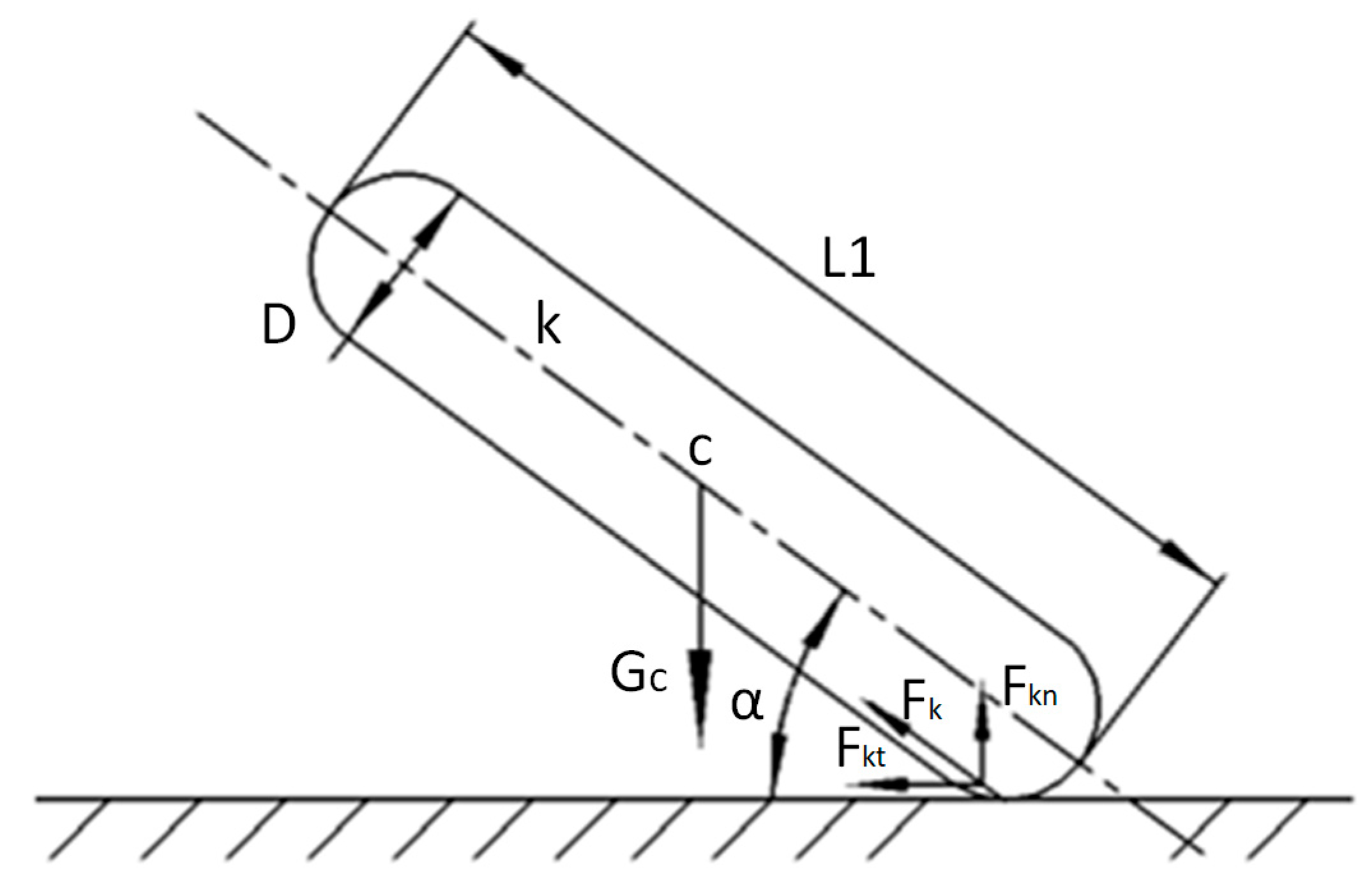
2.1. Coal Impact Theory

As a crucial piece of transportation equipment in the comprehensive mining face, the scraper conveyor operates in a harsh and complex environment. During operation, it is exposed to various impact forces, with the impact energy from falling coal affecting components such as the chain links, scraper, and middle groove. This section primarily focuses on the theoretical analysis of the impact conditions caused by falling coal.
Under ideal absolute dry conditions, coal can be considered a rigid body. However, due to characteristics such as viscosity and moisture content, coal should be treated as a flexible body. Therefore, when analyzing the impact characteristics of coal, coal blocks are typically simplified into a flexible rod model with a diameter of D and a length of L1, based on actual conditions. In the impact collision scenario shown in Figure 1, let the coal block k fall from a height h resulting in a collision impact at the contact point E. The angle between the impact of the falling coal block and the horizontal plane is α1. The center of mass of the coal block simplified as a flexible rod model is denoted as c, and it is subjected to a gravitational force Gc. The impact generates a contact force Fk, which can be decomposed into a tangential force Fkt and a normal force Fkn. Let the unit vector of the impact collision coordinate system be [ i , j , k ] .
The position vector r E of the contact point E of the falling coal block impact in the coordinate system can be expressed as Equation (1):
r E = x i + y j ,
where r E is the position vector.
The position vector of the center of mass c of the simplified flexible rod model of the coal block in the coordinate system is shown in Equation (2):
r c = [ x i + ( y + δ b ) j ] + L 2 [ cos ( θ ) i + sin ( θ ) j ] ,
where δb is the deformation due to impact collision, m.
The angular velocity ω k and angular acceleration α k of the simplified flexible rod of lump coal can be expressed by Equation (3) and Equation (4), respectively:
ω k = θ ˙ c k ,
α k = θ ¨ c k ,
where ω k , α k are angular velocity and angular acceleration.
The velocity v E and acceleration a E at the contact point E of the falling collision are shown in Equation (5) and Equation (6), respectively:
v E = d r c d t + ω k × ( r E r c ) ,
a E = d 2 r c d t 2 + α k × ( r E r c ) + ω k × [ ω k × ( r E r c ) ] ,
where v E , a E are velocity and acceleration.
Based on the Newton–Euler metric, the dynamical equations of the simplified flexible rod for coal briquettes can be obtained by calculations, as shown in Equations (7) and (8):
m k d r c d t = F k t i + ( F k n G c ) j J c α k = ( r E r c ) × ( F k t i + F k n j ) ,
F k t = μ w F k n v E i v E i ,
where mk is the mass of the impacted coal block, kg; and Jc is the rotational inertia of the impacted coal block, kg · m2.
With access to the relevant information [15,16], the collision impact process between objects can be divided into three main phases: the elastic phase, the elastoplastic phase, and the recovery phase. During the elastic and recovery phases, the coal block and the middle groove follow the Hertz contact theory. In the elastoplastic phase, the process is governed by the Jackson–Green theoretical model.
The equivalent radius and equivalent elastic modulus for the impact process of the coal block with the central chute during the elastic stage are shown in Equation (9):
1 E d = 1 v k 2 E k + 1 v f 2 E f 1 R d = 1 R k + 1 R f ,
where Ef and Ek are the modulus of elasticity of the center channel and coal block, respectively, Pa; and Rf and Rk are the Poisson’s ratio of the center channel and coal block, respectively.
During the elastic–plastic stage of the impact process between the coal block and the middle groove, the relationship between the yield deformation δy and the yield strength Sy of the coal block can be calculated using Equations (10)–(12):
δ * = δ δ y ,
δ y = ( π C j S y 2 E d ) 2 R d ,
C j = 1.295 e 0.736 v k ,
where δy is the deformation at the onset of yielding in the impact process of the coal block, m; and Sy is the yield strength of the coal block, Pa.
At the beginning of the elastic–plastic phase of the impact process, the value of δ* is ideally 1, but its true value is ≥1.9, and the contact force Fkep between the coal block and the central chute can be calculated by Equation (13):
F k e p = F k c [ e 0.25 ( δ * ) 5 12 ( δ * ) 1.5 + 4 H G C j S y ( 1 e 0.04 ( δ * ) 5 9 ) δ * ] ,
According to the above equation, there is again
B = 0.14 e ( 23 S y E d ) ,
r a = R d δ y ( δ 1.9 δ c ) B ,
H G S y = 2.84 0.92 [ 1 cos ( π r a R d ) ] ,
F k c = 4 3 ( R d E d ) 2 ( π C j S y 2 ) 3 ,
where HG is the average positive stress, Pa; and Fkc is the critical contact force, N, at the onset of yielding when the collision between the coal block and the center channel occurs.
When the coal block impacting the central chute is in the recovery stage, the contact force Fkr between the coal block and the central chute can be expressed by Equation (18):
F k r = 4 3 E d R r 0.5 ( δ δ r ) 1.5 ,
Style
δ r = δ m ( 1.02 1 δ m / δ y + 5.9 6.9 0.54 ) ,
R r = 1 ( δ m δ r ) 3 ( 3 F k m 4 E d ) 2
where Fkm is the maximum contact force during the elastic–plastic stage of the impact process, N; δm is the maximum deformation of the coal block during the elastic–plastic stage, m; δr is the deformation of the coal block during the recovery stage, m; and Rr is the radius of curvature during the recovery stage, m.

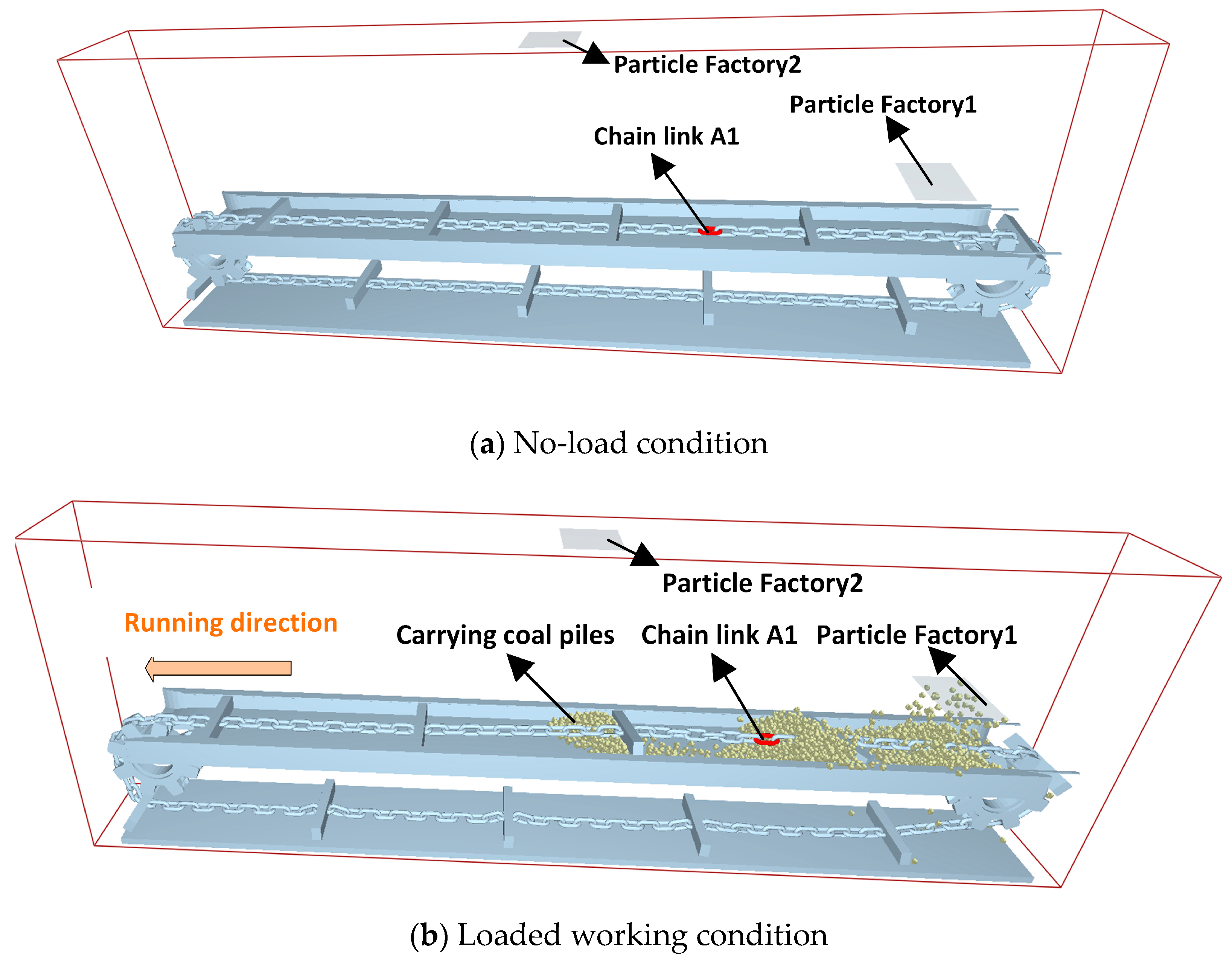
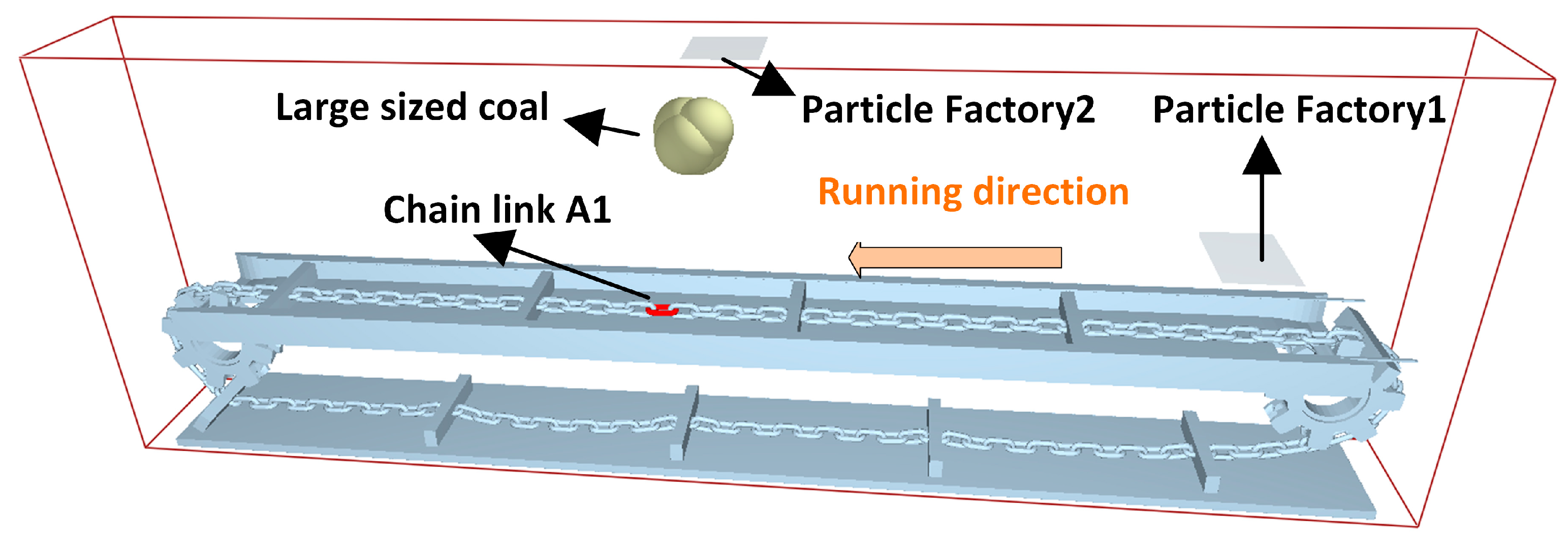
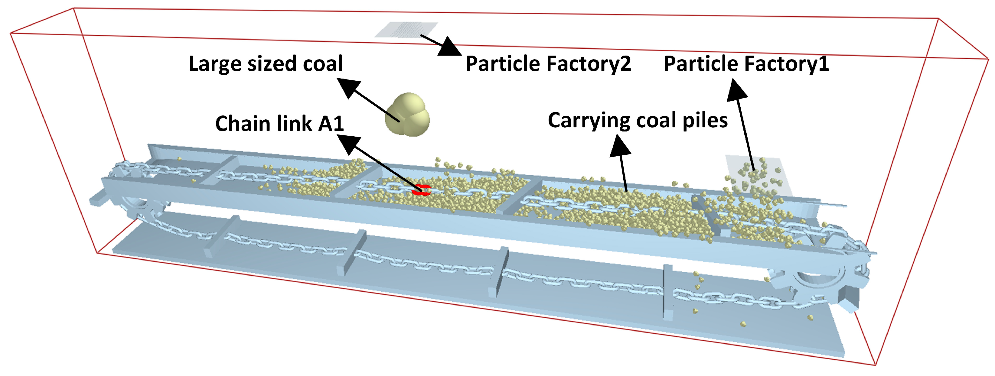
2.2. Adams-EDEM Coupling Model Creation

To ensure the smooth execution of the coupling simulation, the model was simplified. The simplified model includes the central groove, bottom plate, 120 chain rings, 10 scraper plates, a driving sprocket, and a driven sprocket, as shown in Figure 2a; the red border represents the boundary range. The particle factory setup in EDEM 2020 generates coal particles for simulating the scraper conveyor’s working process under no-load and coal-conveying conditions. To achieve this, two-particle factories were added to the EDEM model. Particle Factory 1 simulates the coal mining machine’s roller, continuously generating coal particles that fall onto the scraper conveyor to mimic coal flow. Particle Factory 2 generates large pieces of coal that impact the chain drive system. The corresponding coupled model of the scraper conveyor is shown in Figure 2b. The coal blocks cut by the mining machine have not undergone precipitation and screening, resulting in varying shapes, sizes, and qualities. These coal blocks also contain broken wood, gangue, and other impurities, forming irregular shapes when bonded with loose coal. Simulating and generating all types of raw coal shapes is challenging. To address these issues, the shape of coal particles is simplified to balance simulation speed and accuracy considerations. Since EDEM software version 2.6 can only generate spherical particles, the coal particles are set as a four-particle model to combine actual working conditions with simulation accuracy. The physical radius of a single particle is 23.29 mm, as shown in Figure 3.
The basic parameters of the material properties of coal particles are shown in Table 1.
Actual coal blocks typically have irregular and sharp edges, and simplified geometric models used in EDEM software (such as spherical particles) may not accurately reflect these complex shape differences, resulting in larger surface contact areas and higher friction forces, while spherical particle models may underestimate these factors. In addition, the irregular shape of coal blocks may affect particle accumulation and flowability, resulting in slight deviations between simulation results and actual situations. The research conducted in this article ignores the aforementioned impacts. Coal in real life comes in various sizes and usually follows a certain distribution range. In the simulation, the size distribution of the particle model can be adjusted to set the particle size distribution range to 0.5–1.5 times, making it as close as possible to the size of real coal, thus more accurately reflecting the coal particles under actual conditions.
To facilitate the analysis of the simulation results, the direction of the chain drive system is defined. The X direction is the running direction of the scraper chain, the Y direction is opposite to gravity (longitudinal direction), and the Z direction is perpendicular to both the X and Y directions and parallel to the central groove (transverse direction). The impacted chain ring, named A1, is taken as the research object. The running direction of the scraper chain is defined as the positive direction. The adjacent chain ring on the front side of A1 is named A0, and the adjacent chain ring on the back side is named A2. For easier observation, the chain ring A1 is colored red in the EDEM model.

3. Results and Discussion

3.1. Simulation Programming

This paper conducts a simulation study on the stable running condition of the scraper conveyor, the unloaded coal impact condition, and the loaded coal impact condition. The study aims to understand the influence of the loaded coal pile on the dynamics of the chain drive system under these conditions. The findings provide a basis for the structural design and optimization of the chain drive system. The chain drive system produces violent vibrations during stable operation and when impacted by large coal. The contact force of the chain ring and the acceleration of the scraper fluctuate drastically. This paper primarily analyzes these fluctuations to study the vibration behavior of the system.
Combining the above analysis, a total of eight sets of comparison experiments need to be conducted. The specific parameters for each set of simulations are shown in Table 2.

3.2. Simulation and Analysis of Chain Drive System under Stable Operating Conditions

First, the working conditions of the scraper conveyor in steady-state operation are simulated. Simulations are conducted for both unloaded and loaded conditions. The particle generation speed of Particle Factory 1 is set to 0 kg/s for the unloaded condition and 30 kg/s for the loaded condition. The simulation process for both conditions is illustrated in the schematic diagram in Figure 4.

3.2.1. Chain Ring Contact Force Analysis

A comparison of the three-way contact force between the statistical chain ring A1 and the rear side chain ring A2, under unloaded and loaded conditions, is shown in Figure 5.
As shown in the Figure 5, the transverse contact force between chain rings under no-load conditions is essentially zero. The longitudinal contact force is also nearly zero during the smooth operation stage, except for force spikes caused by the polygonal effect during the sprocket chain ring engagement. The contact force in the operational direction is relatively smooth, with smaller fluctuations compared to the loaded condition, except during the engagement stage. Under loaded conditions, the transverse contact force between the chain rings fluctuates slightly at 4.09 s, with an amplitude of 338 N, as chain ring A1 engages with the sprocket and re-enters the middle groove area. The longitudinal contact force and running direction contact force between chain rings changes earlier than under no-load conditions. This is due to the resistance in the chain drive system after the coal pile is loaded onto the scraper conveyor, which tensions the chain, leading to an earlier change in the longitudinal and running direction contact forces. During the stable operation stage, the longitudinal contact force is smaller than that of the no-load condition, as the coal pile reduces the longitudinal jumping of the chain. The running direction contact force between chain rings remains larger compared to the no-load condition. This is because the loaded coal pile creates resistance in the chain drive system. Based on the operating principle of the scraper conveyor, the loaded coal pile is pushed forward by the scraper, which is fixed to the scraper chain. Consequently, the scraper chain is under tension in the running direction, resulting in a larger contact force between the chain rings.
The contact forces in the transverse, longitudinal, and running directions of the chain ring under no-load conditions are recorded and shown in Table 3 and Figure 6. It is evident that regardless of the load, the contact force in the running direction of the chain ring is greater than in the transverse and longitudinal directions. This indicates that the scraper conveyor experiences the greatest force in the running direction under both conditions. Therefore, deformation such as stretching is most likely to occur first in the running direction of the chain.

3.2.2. Scraper Vibration Acceleration Analysis

The acceleration data of the scraper on the back side of the impacted chain ring A1 were recorded and their dynamic characteristics were analyzed. The acceleration of the scraper in the transverse, longitudinal, and running directions is shown in Figure 7.
As seen in Figure 7, the vibration acceleration of the scraper in all directions under no-load conditions fluctuates less. The acceleration vibration of the scraper in the three directions under the load condition is greater than that under the no-load condition, consistent with the chain ring’s vibration. The scraper’s vibration acceleration in the running direction fluctuates drastically at 4.8 s, caused by the sudden loading of coal onto the scraper conveyor at a speed of 30 kg/s. This impact affects the chain drive system, causing the scraper’s acceleration to fluctuate in all directions. Comparing the vibration acceleration in three directions under no-load and loaded conditions, it is evident that the running direction has the largest acceleration, followed by longitudinal and, lastly, transverse vibration acceleration. This indicates that the running direction is the primary direction for acceleration fluctuation. Numerically, except for the larger acceleration fluctuation during the coal pile loading stage, the fluctuations at other times are relatively small.

3.3. Simulation and Analysis of Shock in Chain Drive System under No-Load Condition

To simulate and analyze the dynamic characteristics of the scraper conveyor under impact conditions with no load, the particle generation speed of Particle Factory 1 in EDEM is set to 0 kg/s. Particle Factory 2 generates one particle with the simulation time set to 10 s. The coal particles are generated at the 5.9-second mark to simulate large lumps of coal or gangue impacting the scraper conveyor during coal mining. Figure 8 shows the impact simulation schematic of the chain drive system under no-load conditions. Finally, the simulation results are exported, and data processing is carried out.

3.3.1. Chain Ring Impact Analysis

By observing the simulation model and process, the forces in the transverse, longitudinal, and running directions for the impacted chain ring A1 are extracted. The impact forces endured by the chain ring under no-load conditions, with coal briquettes weighing 20 kg, 40 kg, and 60 kg, are illustrated in Figure 9.
From the above figure, it is evident that under unloaded conditions, the scraper conveyor experiences significant impact forces when struck by falling coal. The impact force on the transverse direction of chain ring A1 is 1255.06 N with 20 kg coal, 10,038.59 N with 40 kg coal, and 20,161.88 N with 60 kg coal. The longitudinal impact force is 8127.48 N with 20 kg coal, 68,941.46 N with 40 kg coal, and 138,400 N with 60 kg coal. The impact force in the running direction is 2260.55 N with 20 kg coal and 8188.12 N with 40 kg coal.
It can be observed that the impact force in all three directions surges when the chain drive system is hit by falling coal. Among them, the longitudinal impact force exhibits the largest amplitude, while the running direction impact force shows the smallest amplitude. This indicates that longitudinal vibration is the primary cause of chain ring failure during coal impact events. Meanwhile, from the above figure, it can be seen that when the chain ring is subjected to the impact of different masses of coal blocks, as the mass of the impacted coal blocks increases from 20 kg to 60 kg, the three-way impact force that the chain ring is subjected to is growing bigger and bigger, and the amplitude of the impact force in the transverse, longitudinal and running directions is counted, as shown in Figure 10.
From the above figure, it can be seen that as the mass of the impacting coal block increases, the impact force experienced by chain ring A1 demonstrates a strong linear relationship. By performing linear fitting on the amplitude of the longitudinal impact force, as shown in Figure 11, the coefficient of determination (R2) is 0.99853. This indicates a strong linear correlation between the mass of the coal block and the longitudinal impact force on the scraper conveyor’s chain ring: F = 3256.81 x 58449.54 .

3.3.2. Chain Ring Contact Force Analysis

When the scraper conveyor is impacted by large lumps of coal, the chain ring experiences a sudden and significant impact load, causing abrupt changes in the three-way contact force between the chain rings. For instance, the statistics for a 20 kg lump coal impact show the variation in the three-way contact force between chain ring A1 and its adjacent chain ring A2, as depicted in Figure 12.
From the figure, it is evident that the contact forces in the three directions of the chain ring during a 20 kg lump coal impact exhibit varying degrees of change. The transverse contact force increases from 0.566 N to 971.68 N, resulting in a rise of 971.11 N. The longitudinal contact force changes from −66.29 N to −1360.80 N, with an amplitude of 1294.51 N. The running direction contact force shows cyclic variations with a significant range: the minimum value is 13,014.83 N, the maximum is 20,936.28 N, and the amplitude is 7921.45 N.
Among these, the running direction contact force is the largest, while the transverse contact force is the smallest. This indicates that the chain rings experience the greatest force in the running direction during impacts, leading to increased pitch and potential chain breakage. This suggests that the chain rings are most likely to suffer failure, such as increased pitch and link breakage, under impact conditions. Statistical chain ring A1 under 40 kg and 60 kg lump coal impact conditions and chain ring A1 and its rear side chain ring A2 three-way contact force changes are shown in Figure 13.
From the figure, it is observed that under the impact of a 40 kg coal block, the contact forces between the chain rings change significantly: the transverse contact force increases from 0.12 N to 876.99 N, with a rise of 876.87 N; the longitudinal contact force rises from 20.74 N to 1720.22 N, resulting in an increase of 1699.48 N; and the running direction contact force increases from 12,578.78 N to 20,839.33 N, with an increase of 8260.55 N. In the case of a 60 kg coal block impact, the changes are even more pronounced: the transverse contact force increases from 2.39 N to 2237.17 N, an increase of 2234.78 N; the longitudinal contact force rises from 38.47 N to 12,568.59 N, showing an increase of 12,530.12 N; and the running direction contact force goes up from 12,611.61 N to 22,635.98 N, an increase of 10,024.37 N. This demonstrates that with the increase in the mass of the impacting coal block, the contact forces in all directions (transverse, longitudinal, and running) increase substantially, indicating a higher impact load on the chain rings.

3.3.3. Scraper Vibration Acceleration Analysis

The statistics for the scraper conveyor in different mass falling coal impact, the impact chain ring A1 back side of the scraper acceleration data and the analysis of their dynamic characteristics, and scraper transverse, longitudinal, and running direction acceleration are shown in Figure 14.
From the figure, it can be observed that unlike the stable operation condition, when the scraper conveyor is impacted by falling coal under no-load conditions, the scraper’s acceleration experiences violent vibrations at the moment of impact, gradually recovering to zero afterward. The longitudinal direction is the primary vibration direction for the scraper’s acceleration. The longitudinal acceleration of the scraper under the impact of a 20 kg lump of coal is 4533.79 m/s2, under a 40 kg lump of coal is 8785.07 m/s2, and under a 60 kg lump of coal is 14,890.53 m/s2. This indicates a nearly linear increase in longitudinal acceleration with the mass of the falling coal. The figure also shows that although the maximum acceleration fluctuation occurs in the longitudinal direction, the transverse acceleration fluctuation persists the longest. This prolonged transverse vibration is attributed to model simplifications and the torsional effects in the chain drive system of the scraper conveyor during the coal impact. To enhance stability, the coordination between the scraper and the middle groove should be optimized to reduce torsional and swaying phenomena during impacts.

3.4. Simulation and Analysis of the Impact of Chain Drive System under Loaded Condition

Finally, the dynamics of the scraper conveyor under loaded conditions when impacted by different masses of coal blocks are analyzed. In the EDEM software, the number of particles generated by Particle Factory New Factory1 is set to unlimited with a particle generation speed of 30 kg/s, simulating the transported coal pile from the coal miner to the scraper conveyor under actual working conditions. The total number of particles generated by Particle Factory New Factory2 is set to 1, with the particle generation time set to 5.0 s and the simulation time to 10 s. The simulation process of the impact of large lumps of coal on the scraper conveyor under loaded conditions is shown in Figure 15.

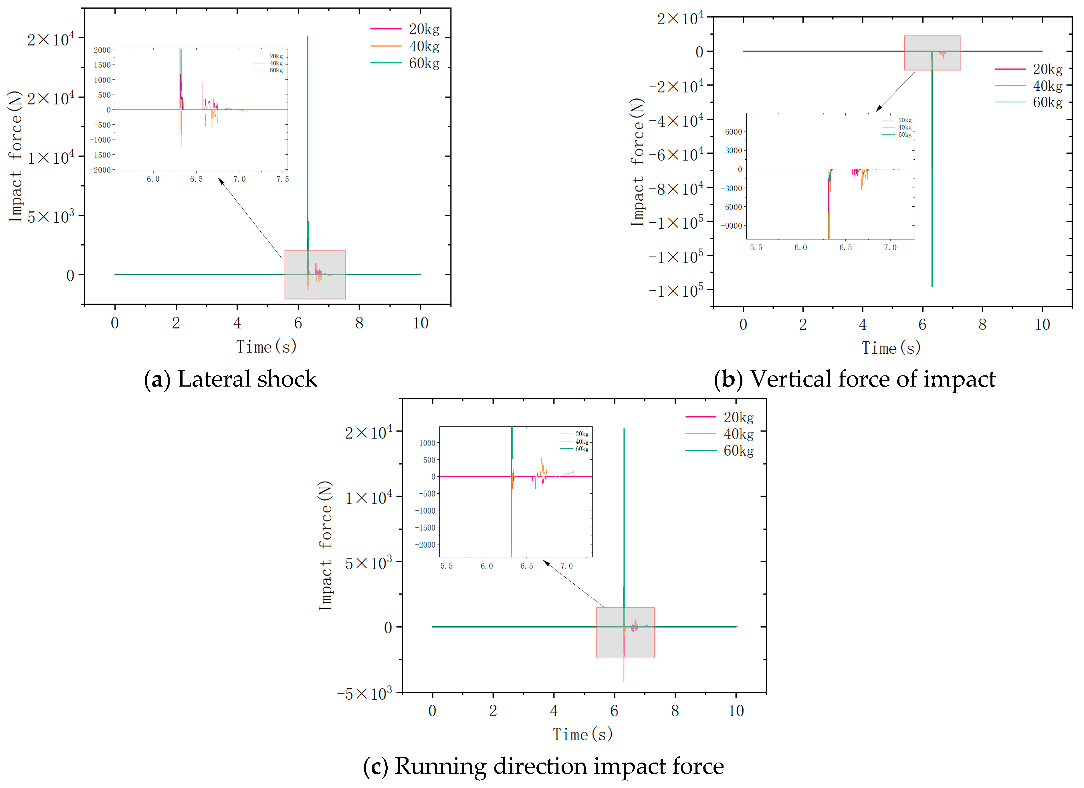
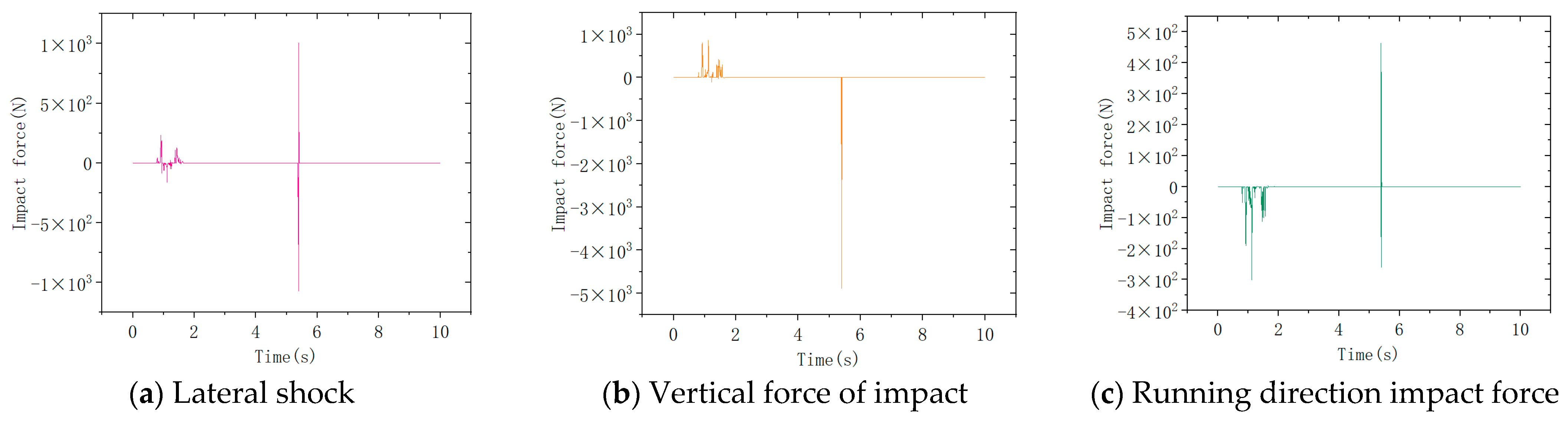
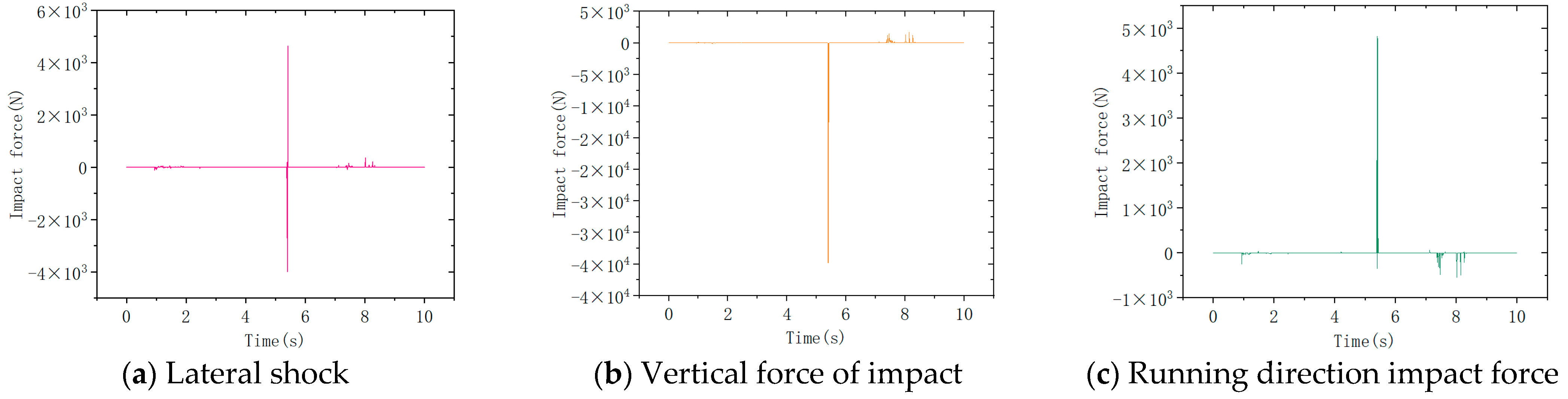
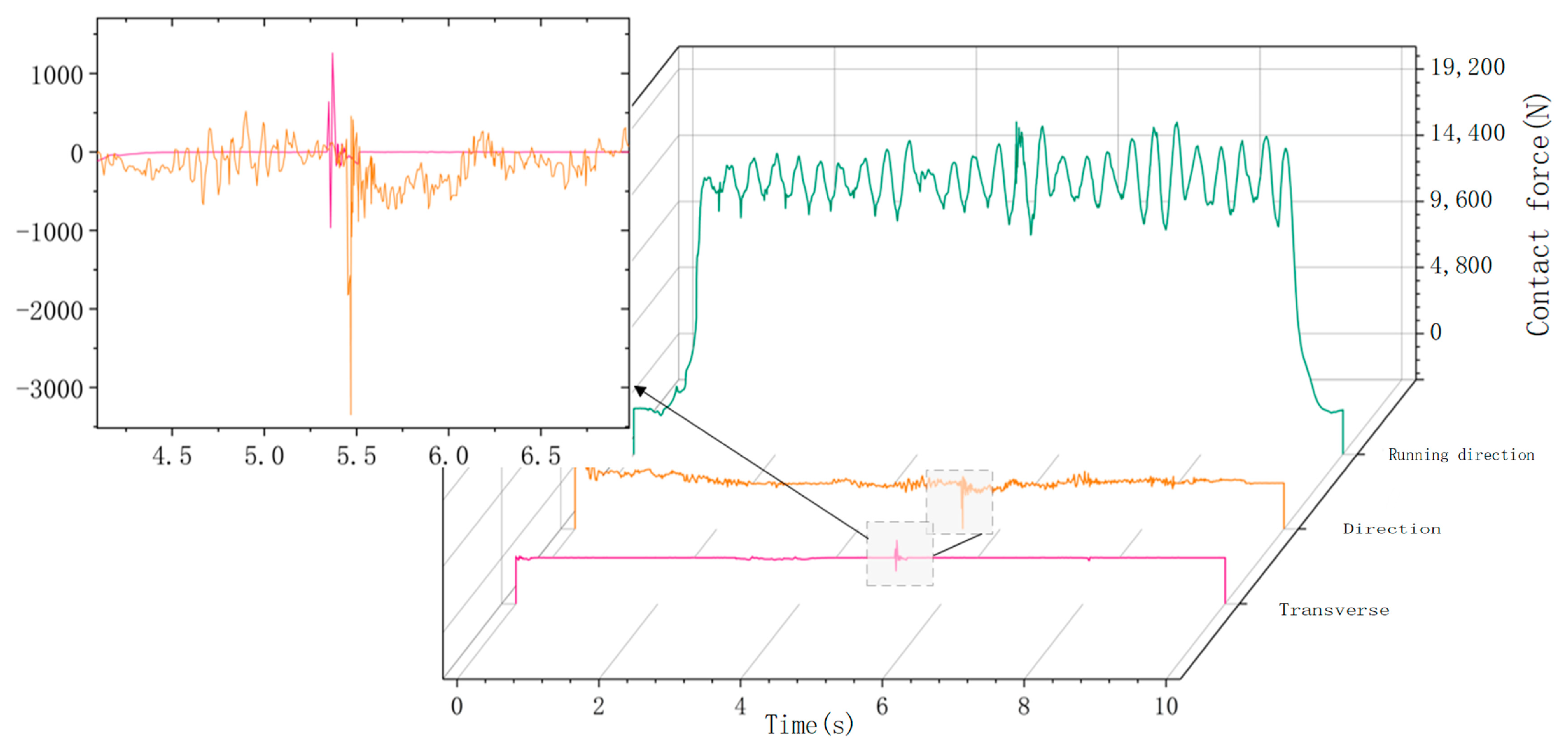
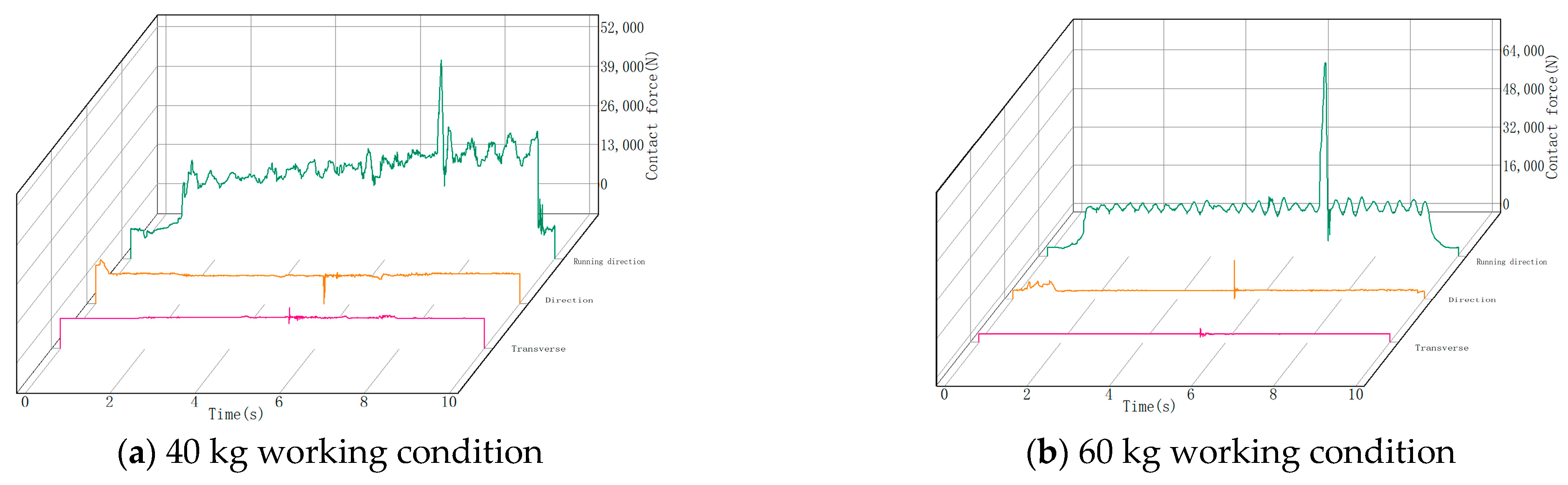
3.4.1. Chain Ring Impact Analysis

Firstly, the impact force on the chain ring under loaded conditions is analyzed. Based on the previous analysis, large lumps of coal are generated at 5.9 s into the simulation. The chain ring impacted by the lump coal is numbered Lianhuan102 (equivalent to chain ring A1). The three-directional impact forces on chain ring A1 are examined for coal lumps with masses of 20 kg, 40 kg, and 60 kg. The three-way impact force under the condition of a 20 kg falling coal impact is shown in Figure 16.
The three-way impact force for the 40 kg falling coal impact condition is shown in Figure 17:
The three-way impact force for the 60 kg falling coal impact condition is shown in Figure 18:
The figure above shows the impact of falling coal on the chain drive system under load. When a 20 kg lump of coal hits the chain ring, it experiences a transverse force of 1072.44 N, a longitudinal force of 4887.14 N, and an impact force in the running direction of 462.82 N. With a 40 kg lump of coal, the chain ring faces a transverse force of 4629.79 N, a longitudinal force of 34,817.80 N, and an impact force in the running direction of 4828.05 N. For a 60 kg lump of coal, the transverse force is 4629.79 N, the longitudinal force is 34,817.80 N, and the impact force in the running direction is 4828.05 N. Finally, with the same 60 kg lump of coal, the chain ring endures a transverse impact force of 12,596.68 N, a longitudinal impact force of 79,985.56 N, and an impact force in the running direction of 7523.56 N.
Figure 19 shows a comparison of the amplitude of the three-way impact force on chain ring A1 under loaded and unloaded conditions.
Firstly, comparing the lateral impact force on the chain ring, the impact of a 20 kg lump of coal decreases from 1255.06 N in the unloaded condition to 1072.44 N in the loaded condition, a reduction of 14.55%. For a 40 kg lump of coal, the force drops from 10,038.59 N to 4629.79 N, a decrease of 53.88%. With a 60 kg lump of coal, the force changes from 20,161.88 N to 12,596.68 N, which is 37.52% less. The impact force of a 60 kg lump of coal decreases by 37.52% from 20,161.88 N in the unloaded condition to 12,596.68 N under load.
Secondly, the longitudinal impact force on the chain ring decreases as follows: for a 20 kg lump of coal, it reduces by 39.87%, from 8127.48 N in the unloaded condition to 4887.14 N in the loaded condition. For a 40 kg lump, the force decreases by 49.50%, from 68,941.46 N to 34,817.80 N. With a 60 kg lump of coal, the impact force reduces by 42.21%, from 138,400 N to 79,985.56 N. This represents a 42.21% decrease from 138,400 N in the unloaded condition to 79,985.56 N under load.
Finally, the impact force in the running direction of the chain ring changes as follows: For a 20 kg lump of coal, it decreases by 79.53%, from 2260.55 N in the unloaded condition to 462.82 N in the loaded condition. For a 40 kg lump, the force reduces by 41.04%, from 8188.12 N to 4828.05 N. With a 60 kg lump of coal, the impact force decreases by 50.42%, from 15,175.98 N to 7523.56 N. This represents a 50.42% reduction for the 60 kg lump of coal, from 15,175.98 N in the unloaded condition to 7523.56 N under load.
The comparison shows that the impact force on the scraper conveyor in all three directions is smaller under loaded conditions compared to unloaded conditions. As the quality of the lump coal increases, the reduction in impact force becomes more significant. This occurs because when the scraper conveyor is impacted by lump coal, the force first hits the loaded coal pile. This pile absorbs some of the impact, resulting in less force being transferred to the chain ring. With larger coal lumps, the coal pile absorbs more of the impact force, further reducing the force that reaches the chain ring compared to the unloaded condition.

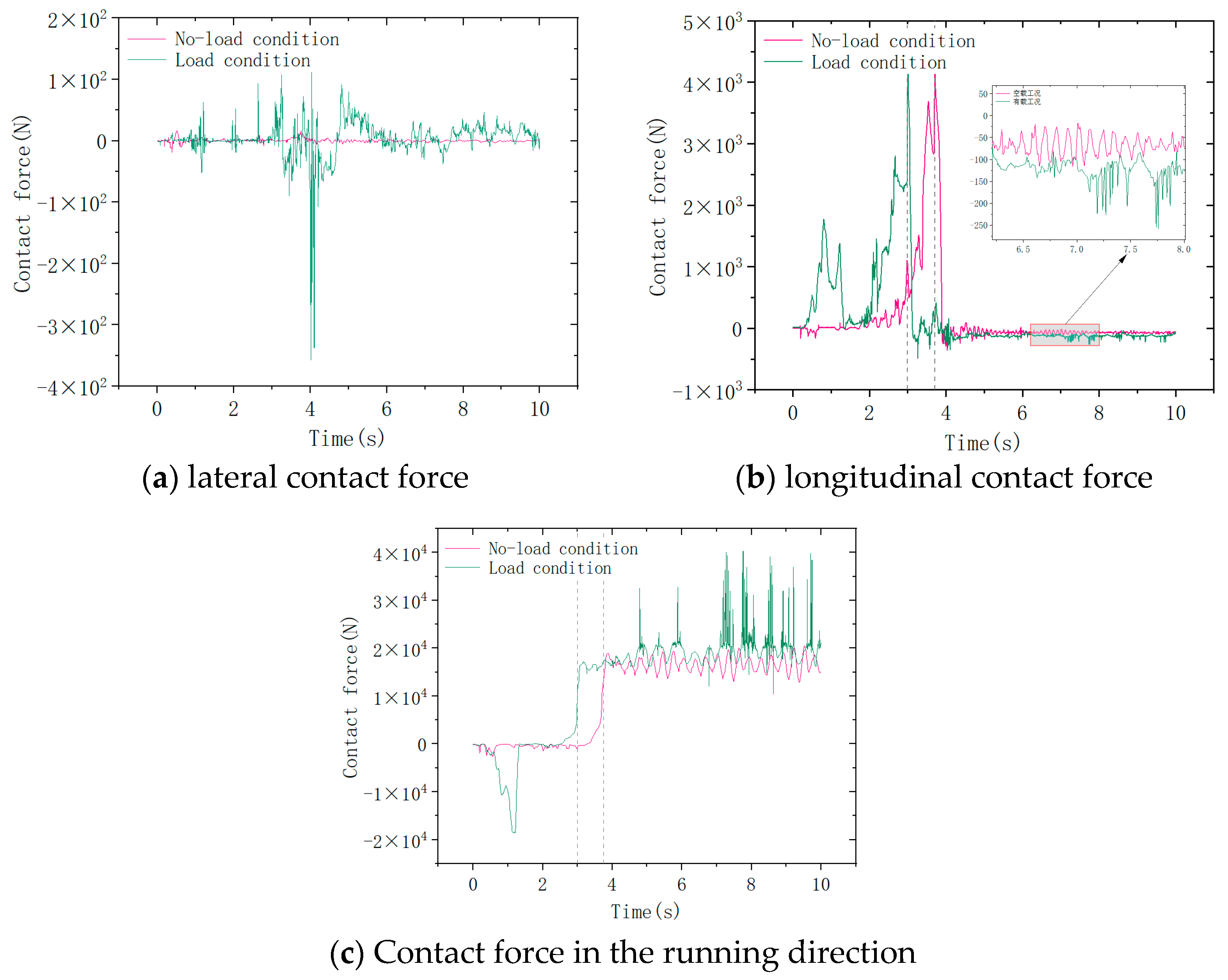
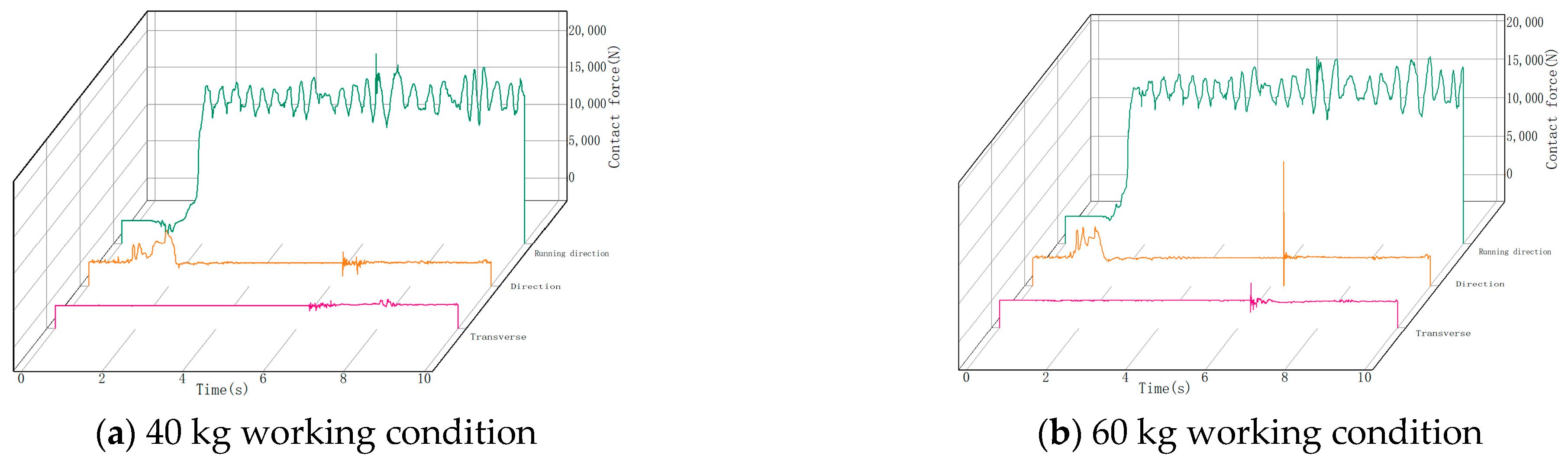
3.4.2. Analysis of Contact Force in Chain Links

Figure 20 shows the change in contact force between chain ring A1 and its rear side chain ring A2 when the chain drive system is impacted by a 20 kg lump of coal under statistically loaded conditions.
As shown in the figure, when the scraper conveyor is impacted by a 20 kg lump of coal, the contact forces between the chain rings change suddenly. The transverse contact force increases by 1259.5 N, from 2.34 N to 1261.84 N. The longitudinal contact force rises by 3190.19 N, from 156.8 N to 3346.99 N. The contact force in the running direction fluctuates cyclically with higher values. The minimum fluctuation is 12,599.96 N, the maximum is 20,839.33 N, and the fluctuation range is 8239.37 N. As in the no-load condition, the contact force in the running direction remains the largest, while the transverse contact force is the smallest. Compared to the no-load simulation, the running direction contact force is still the highest, and the longitudinal contact force is the lowest. Therefore, under loaded impact conditions, the contact force in the running direction is the main cause of deformation in the impacted chain ring.
Figure 21 shows the variation in the three-way contact force between chain ring A1 and the rear side chain ring A2 under the impact conditions of 40 kg and 60 kg lump coal.
From the figure, it can be seen that under the impact condition of a 40 kg lump of coal, the transverse contact force between the chain rings changes from 240.94 N to 3346.5 N, an increase of 3105.56 N. The longitudinal contact force changes from 635.81 N to 10,040.51 N, an increase of 9404.7 N. The contact force in the running direction fluctuates with a minimum of 14,135.60 N, a maximum of 56,024.11 N, and a fluctuation range of 41,888.51 N; Under the impact condition of a 60 kg lump of coal, the transverse contact force changes from 230.4 N to 4234.17 N, an increase of 4003.77 N. The longitudinal contact force changes from 714.32 N to 22,568.59 N, an increase of 21,854.27 N. The contact force in the running direction fluctuates with a minimum of 12,760.93 N, a maximum of 75,475.05 N, and a fluctuation range of 62,714.12 N.
The amplitude of the three-way contact force is counted when the chain ring is subjected to impact under loaded and unloaded conditions, and a comparison is made as shown in Figure 22.
The comparison in Figure 22 shows the amplitude of the three-way contact force between chain rings under loaded and unloaded conditions. For a 20 kg lump of coal, the lateral contact force increases from 971.68 N (unloaded) to 1261.84 N (loaded), an increase of 29.86%. For a 40 kg lump, it rises from 876.99 N to 3346.5 N, an increase of 281.59%. For a 60 kg lump, it changes from 2237.17 N to 4234.17 N, an increase of 89.26%. The longitudinal contact force for a 20 kg lump changes from 1360.8 N (unloaded) to 3346.99 N (loaded), an increase of 145.96%. For a 40 kg lump, it increases from 1720.22 N to 10,040.51 N, a 483.68% increase. For a 60 kg lump, it changes from 1250.5 N to 10,040.51 N, also an increase of 483.68%.In the running direction, the contact force for a 20 kg lump rises from 15,936.28 N (unloaded) to 20,839.33 N (loaded), an increase of 30.77%. For a 40 kg lump, it goes from 20,839.33 N to 56,024.11 N, an increase of 168.84%. For a 60 kg lump, it changes from 12,568.59 N to 22,258.65 N, an increase of 77.10%. These results confirm that the amplitude of the three-way contact force is larger under loaded conditions compared to unloaded conditions. The loaded coal pile increases resistance, causing the chain to tense and resulting in higher contact forces between the chain rings. This supports the conclusion in Section 3.2 that the loaded coal pile intensifies the contact forces. The running direction force remains the largest, followed by the longitudinal and then the transverse forces, consistent with the no-load condition. This verifies the accuracy of the simulation results for the no-load condition.

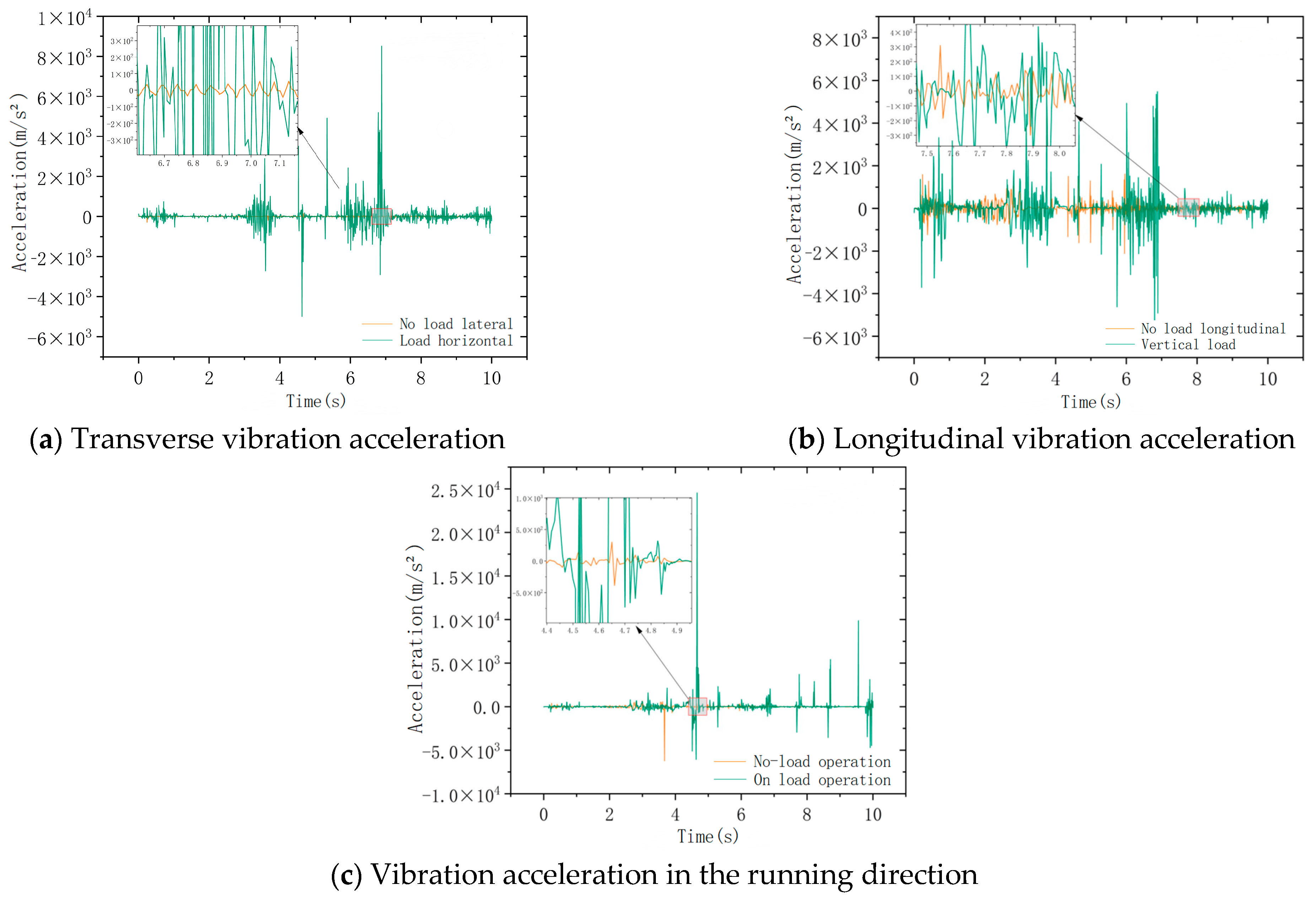
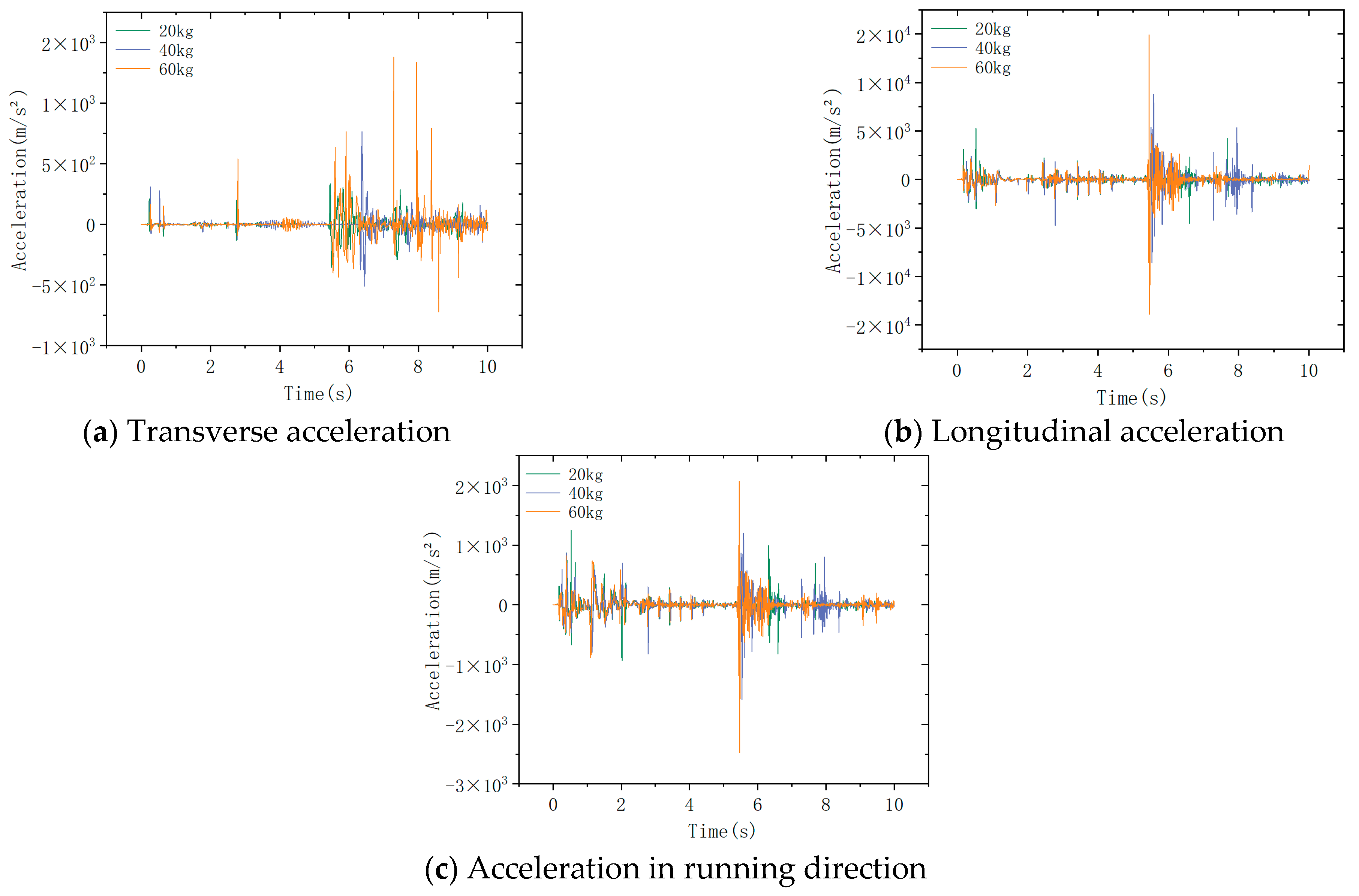
3.4.3. Scraper Vibration Acceleration Analysis

Figure 23 shows the statistical data on the three-way acceleration of the scraper on the back side of the impacted chain ring A1 when the scraper conveyor is subjected to different masses of falling coal under loaded conditions.
As shown in the figure, unlike the unloaded condition, the three-way acceleration of the scraper under loaded conditions fluctuates to varying degrees before being impacted by the falling coal. This occurs because the simulation sets a higher speed for coal particles, causing smaller particles to become trapped beneath the scraper during coal transport. This results in irregular jumps and prevents the scraper from moving smoothly along the central slot. Consequently, the three-way acceleration fluctuates. When the chain drive system is impacted by falling coal, the three-way acceleration of the scraper changes abruptly, with the longitudinal acceleration being the highest and the transverse acceleration the lowest. Figure 24 presents the statistics and comparison of the three-way acceleration amplitude of the scraper under no-load and loaded conditions.
The figure shows that unlike the chain ring acceleration, the three-way acceleration amplitude of the scraper under loaded conditions is larger than under unloaded conditions. As the quality of the falling coal increases, the scraper’s three-way acceleration also increases. Among these, the longitudinal acceleration is the greatest. For a 20 kg lump of coal, the scraper’s longitudinal acceleration increases from 4533.79 m/s2 under unloaded conditions to 10,465.89 m/s2 under loaded conditions, an increase of 130.84%. For a 40 kg lump, the acceleration rises from 8785.07 m/s2 to 13,095.86 m/s2, also a 130.84% increase. For a 60 kg lump, the acceleration changes from 14,890.53 m/s2 under unloaded conditions to 28,605.82 m/s2 under loaded conditions, an increase of 92.11%. The longitudinal acceleration shows the most significant change, indicating that the loaded coal pile excites the three-directional vibration of the scraper, with the longitudinal effect being the most pronounced. To reduce scraper vibration and failure risk, optimizing the fit between the scraper and the central trough in the longitudinal direction is recommended.

4. Conclusions

In this paper, an impact coupling simulation model of the scraper conveyor chain drive system is established. The dynamic characteristics of the system under the impact of falling coal are systematically investigated using a “theory-simulation” approach. The contact force and impact force of the chain ring under different working conditions are compared and analyzed. The following conclusions are reached:
(1)
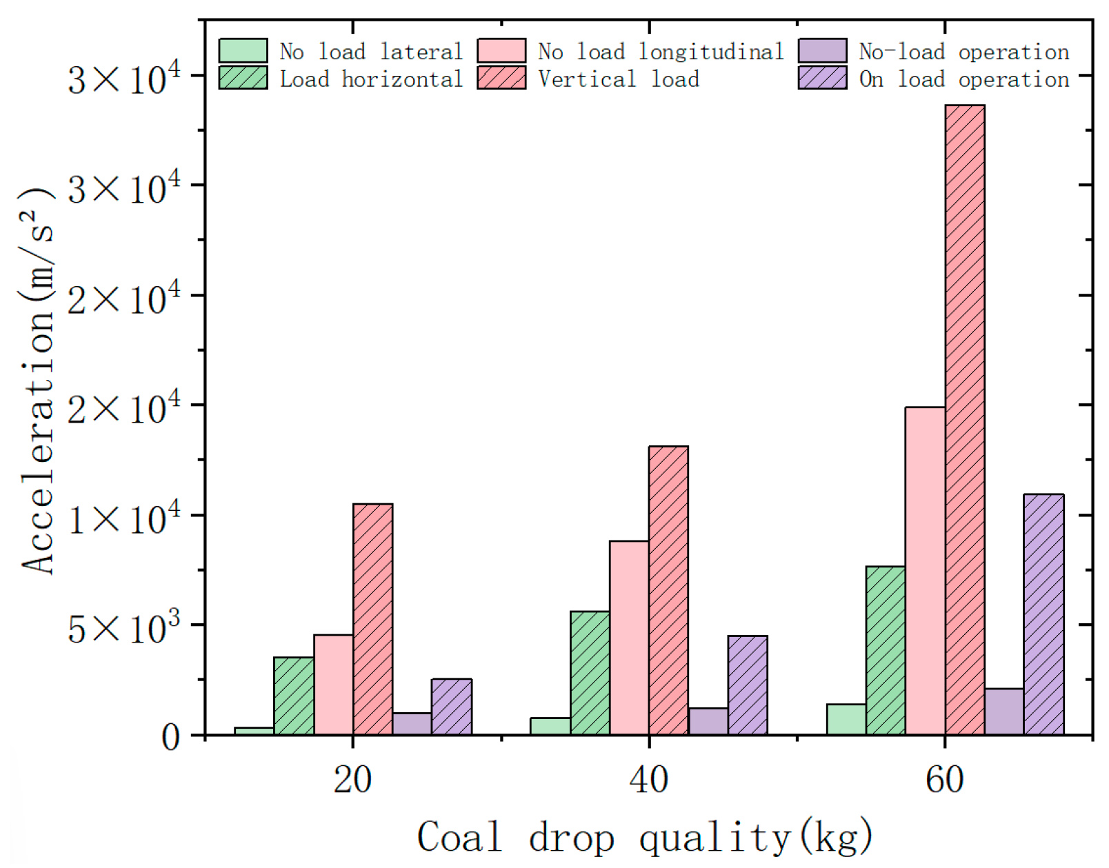
The acceleration of the scraper in all three directions under loaded conditions is greater than under unloaded conditions, with the highest acceleration occurring in the running direction. The loaded coal pile increases the speed of the driven sprocket.
(2)
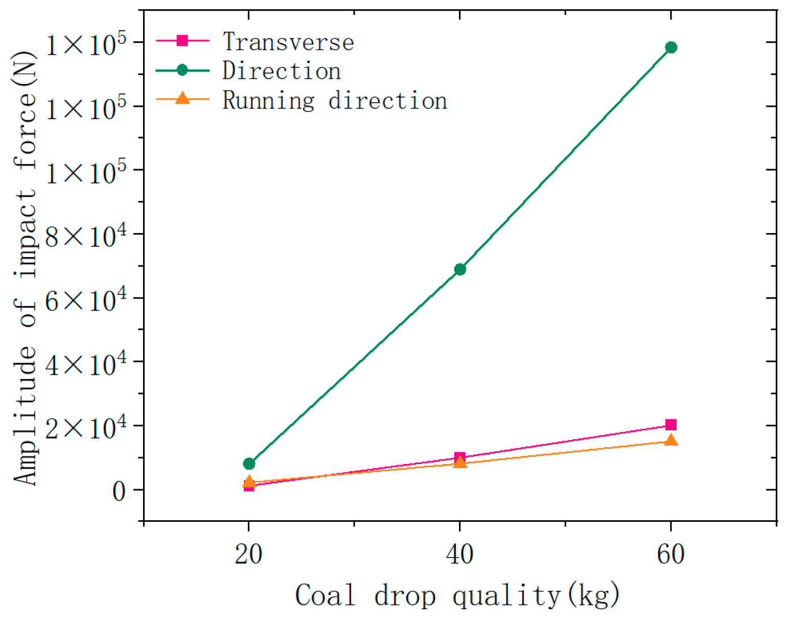
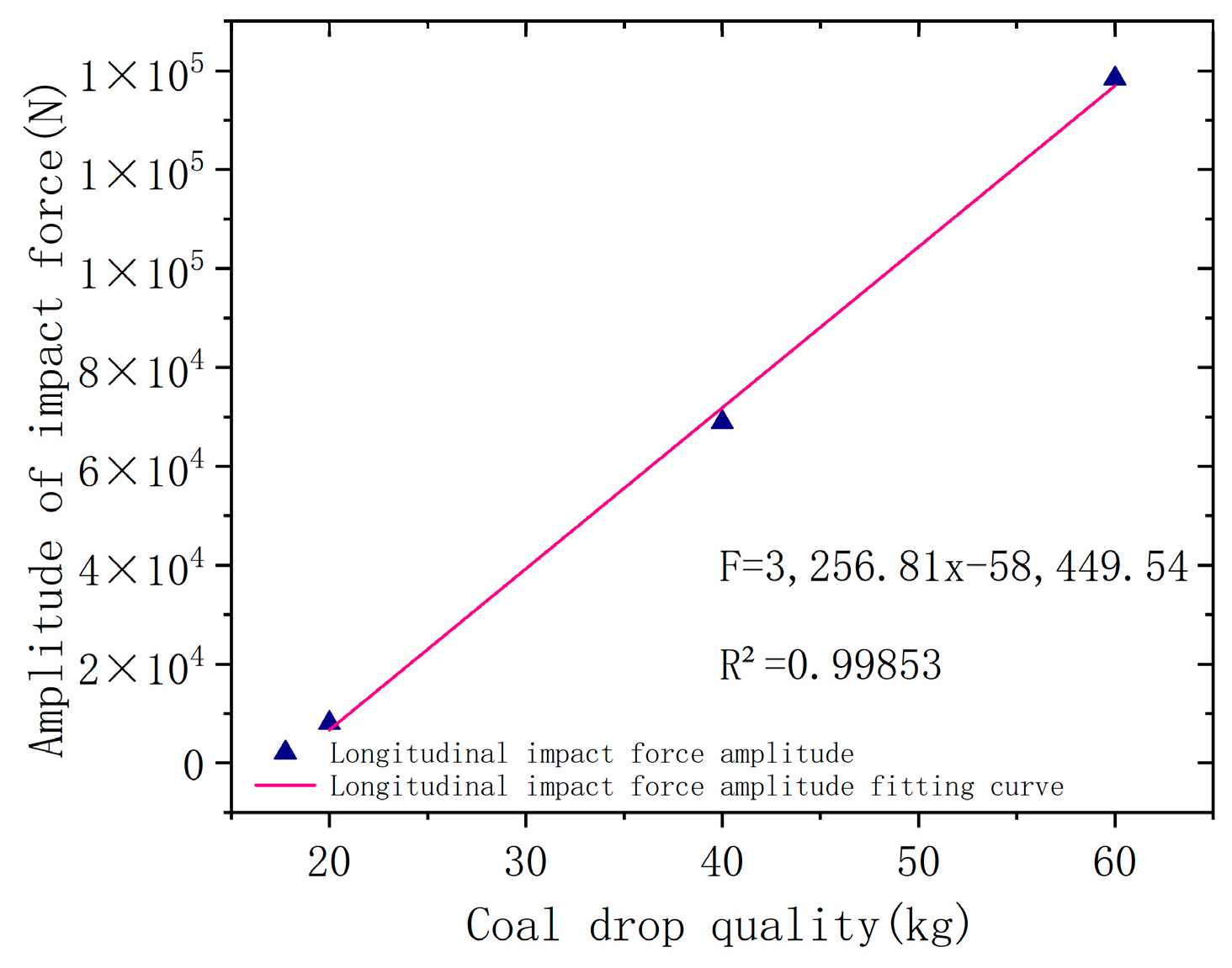
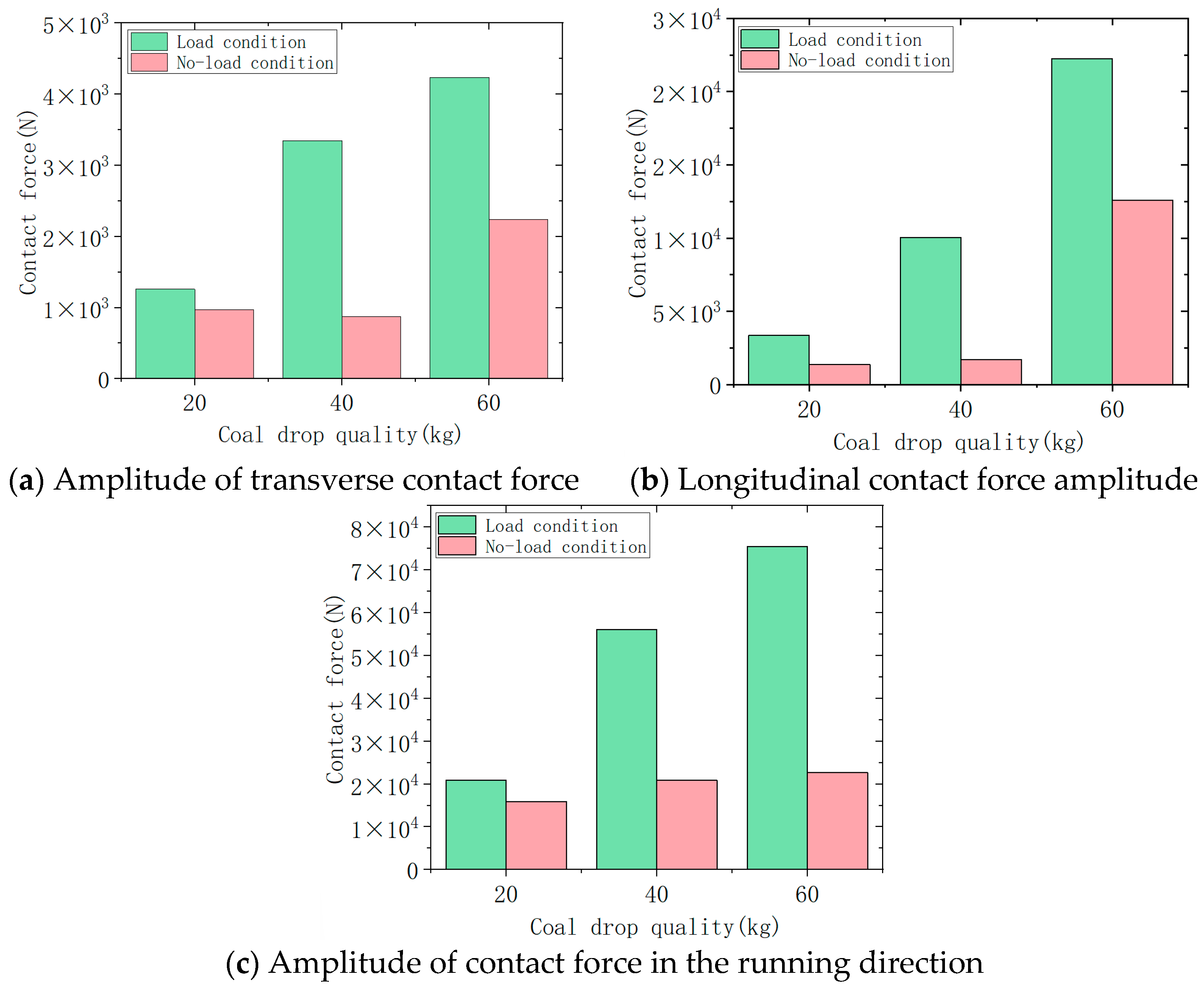
As the mass of falling coal increases, the longitudinal impact force on the chain ring exhibits a clear linear relationship: F = 3256.81 x 58449.54 . The maximum acceleration fluctuation of the scraper occurs in the longitudinal direction, while the transverse acceleration fluctuation lasts the longest.
(3)
Compared to the unloaded condition, the loaded coal pile in the loaded condition reduces the three-way impact force and three-way acceleration fluctuations experienced by the chain ring due to its cushioning and stabilizing effects. However, the three-way contact force between the chain rings is greater than in the unloaded condition. Thus, under the impact of falling coal, the loaded coal pile has a damping effect on the vibration of the chain drive system but increases the contact force between the chain rings.
The findings indicate that the dynamic characteristics of the scraper conveyor vary significantly under different working conditions. By comparing and analyzing the impact force and contact force of the chain ring and scraper under various conditions, the accuracy of the impact coupling model of the scraper conveyor is confirmed. This provides a crucial theoretical basis for the design and optimization of the chain drive system, contributing to improved mining efficiency and enhanced safety in coal mining operations. However, due to limitations in the simulation conditions, there is a gap between the simplified model and the real environment. The current model does not fully simulate the impact of terrain changes on dynamic characteristics under impact working conditions. The future research will focus on improving the model to better reflect real environmental conditions and incorporating terrain factors to enhance the accuracy and applicability of the study.

Author Contributions

Formal analysis, S.J.; funding acquisition, Q.Z.; methodology, Y.Z. and S.J.; supervision, S.C. and W.Q; writing—original draft, Y.Z. and H.Z.; writing—review and editing, W.Q. and Y.Z. All authors have read and agreed to the published version of the manuscript.

Funding

This research was funded by the National Natural Science Foundation of China (52204143, 52234005), the China Postdoctoral Science Foundation (Grant No. 2023M742140), Qingdao Postdoctoral Funding Project (QDBSH20230102027), and the Shandong Provincial Key Laboratory of Mining Machinery Engineering Open Fund (University-Enterprise Joint Funding Project, 2022KLMM307).

Data Availability Statement

The original contributions presented in the study are included in the article, further inquiries can be directed to the corresponding author.

Acknowledgments

The authors acknowledge the support of Shandong University of Science and Technology for this study.

Conflicts of Interest

The authors declare no conflicts of interest.

References

  1. Wieczorek, A.N.; Wójcicki, M. Synergism of the Binary Wear Process of Machinery Elements Used for Gaining Energy Raw Materials. Energies 2021, 14, 1981. [Google Scholar] [CrossRef]
  2. Jiang, S.B.; Huang, S.; Mao, Q.H.; Zeng, Q.L.; Gao, K.D.; Lv, J.W. Dynamic Properties of Chain Drive in a Scraper Conveyor under Various Working Conditions. Machines 2022, 10, 579. [Google Scholar] [CrossRef]
  3. Grinschgl, M.; Reich, F.M.; Abeltshauser, R.; Eder, M.; Antretter, T. New approach for the simulation of chain drive dynamics with consideration of the elastic environment. Proc. Inst. Mech. Eng. Part K J. Multi-Body Dyn. 2017, 231, 103–120. [Google Scholar] [CrossRef]
  4. Zhang, D.S.; Mao, J.; Liu, Z.S. Dynamics simulation and experiment on the starting and braking of scraper conveyor. J. China Coal Soc. 2016, 2, 0356. [Google Scholar] [CrossRef]
  5. Xie, C.X.; Liu, Z.X.; Mao, J.; Miao, X.M.; Lu, J.N. Analysis of torsional vibration characteristics of scraper conveyor on chain blocked condition. J. China Coal. Soc. 2018, 8, 1722. [Google Scholar] [CrossRef]
  6. Zhang, P.L.; Li, B.; Wang, X.W.; Liu, C.Y.; Bi, W.J.; Ma, H.Z. The Loading Characteristics of Bulk Coal in the Middle Trough and Its Influence on Rigid Body Parts. Stroj. Vestn. J. Mech. E 2020, 66, 114–126. [Google Scholar] [CrossRef]
  7. Jiang, S.B.; Lv, R.B.; Wan, L.R.; Mao, Q.H.; Zeng, Q.L.; Gao, K.D.; Yang, Y. Dynamic Characteristics of the Chain Drive System of Scraper Conveyor Based on the Speed Difference. IEEE Access 2020, 8, 168650–168658. [Google Scholar] [CrossRef]
  8. Wang, D.G.; Zhang, J.; Zhu, Z.C.; Gang, S.; Xiang, L. Crack initiation characteristics of ring chain of heavy-duty scraper conveyor under time-varying loads. Adv. Mech. Eng. 2019, 11, 1687814019880366. [Google Scholar] [CrossRef]
  9. Zhang, Q.; Zhang, R.X.; Tian, Y. Scraper Conveyor Structure Improvement and Performance Comparative Analysis. Strength Mater. 2020, 52, 683–690. [Google Scholar] [CrossRef]
  10. Cundall, P.A. A computer model for simulating progressive, large-scale movement in blocky rock system. In Proceedings of the International Symposium on Rock Mechanics, Nancy, France, 4–6 October 1971; pp. 129–136. [Google Scholar]
  11. Yuan, P.F.; He, B.Y.; Zhang, L.H. Planar dynamic modelling of round link chain drives considering the irregular polygonal action and guide rail. Proc. Inst. Mech. Eng. Part K J. Multi-Body Dyn. 2021, 235, 338–352. [Google Scholar] [CrossRef]
  12. Dai, K.Y.; Zhu, Z.C.; Shen, G.; Li, X.; Tang, Y.; Wang, W. Modeling and Adaptive Tension Control of Chain Transmission System with Variable Stiffness and Random Load. IEEE T Ind. Electron. 2022, 69, 8335–8345. [Google Scholar] [CrossRef]
  13. Jonczy, I.; Wieczorek, A.N.; Podwórny, J.; Gerle, A.; Staszuk, M.; Szweblik, J. Characteristics of hard coal and its mixtures with water subjected to friction. Gospod. Surowcami Min. 2020, 36, 185–201. [Google Scholar] [CrossRef]
  14. Fedorko, G.; Nečas, J.; Zegzulka, J.; Gelnar, D.; Molnár, V.; Tomašková, M. Measurement of amount for steel abrasive material transported by special scraper conveyor. Appl. Sci. 2021, 11, 1852. [Google Scholar] [CrossRef]
  15. Dzidek, B.M.; Adams, M.J.; Andrews, J.W.; Zhang, Z.B.; Johnson, S.A. Contact mechanics of the human finger pad under compressive loads. J. R. Soc. Interface 2017, 14, 20160935. [Google Scholar] [CrossRef] [PubMed]
  16. Thornton, C. Coefficient of restitution for collinear collisions of elastic-perfectly plastic spheres. J. Appl. Mech. 1997, 64, 383–386. [Google Scholar] [CrossRef]
Figure 1. Schematic diagram of simplified model impact collision.
Machines 12 00648 g001
Figure 2. (a) Simplified model of scraper conveyor; (b) EDEM model of scraper conveyor.
Machines 12 00648 g002
Figure 3. Particle model for coal block simulation.
Machines 12 00648 g003
Figure 4. Schematic diagram of the simulation process for stabilized operation conditions.
Machines 12 00648 g004
Figure 5. Comparison of three-way contact force between chain rings.
Machines 12 00648 g005
Figure 6. Average contact force in three directions for chain rings.
Machines 12 00648 g006
Figure 7. Acceleration of scraper three-way vibration.
Machines 12 00648 g007
Figure 8. Schematic diagram of the simulation process of impact under no-load condition.
Machines 12 00648 g008
Figure 9. Three-way impact force on the chain ring.
Machines 12 00648 g009
Figure 10. Amplitude of three-way impact force of chain ring.
Machines 12 00648 g010
Figure 11. Fitted plot of longitudinal impact force amplitude.
Machines 12 00648 g011
Figure 12. Chain ring contact force for 20 kg lump coal impact condition.
Machines 12 00648 g012
Figure 13. Chain ring contact forces for 40 kg and 60 kg lump coal impact conditions.
Machines 12 00648 g013
Figure 14. Acceleration of three-way vibration of scraper.
Machines 12 00648 g014
Figure 15. Simulation process of impact under loaded condition.
Machines 12 00648 g015
Figure 16. Three-way impact force on chain ring for 20 kg lump coal impact condition.
Machines 12 00648 g016
Figure 17. Three-way impact force on chain ring for 40 kg lump coal impact condition.
Machines 12 00648 g017
Figure 18. Three-way impact force on chain ring for 60 kg lump coal impact condition.
Machines 12 00648 g018
Figure 19. Comparison of impact force on chain ring under no-load–loaded condition.
Machines 12 00648 g019
Figure 20. Chain ring contact force for 20 kg lump coal impact condition.
Machines 12 00648 g020
Figure 21. Chain link contact force under impact conditions of 40 kg and 60 kg coal blocks.
Machines 12 00648 g021
Figure 22. Comparison of contact force between chain rings under no-load–loaded condition.
Machines 12 00648 g022
Figure 23. Acceleration of three-way vibration of scraper.
Machines 12 00648 g023
Figure 24. Comparison of scraper acceleration for no-load–loaded condition.
Machines 12 00648 g024
Table 1. Basic parameters of coal pellet materials.
AttributeParticle Radius (mm)Particle Density (kg/m3)Young’s Modulus (Pa)Shear Modulus (Pa)Poisson’s Ratio
numerical value38.87801 2.07 × 10¹¹ 8.02 × 10100.29
Table 2. Simulation parameter settings.
GroupsOperational StateCoal TransportationFalling Coal Mass (kg)
1Run smoothlyNo-load condition-
2Loaded working condition-
3Impact conditionNo-load condition20
440
560
6Loaded working condition20
740
860
Table 3. Average contact forces in three directions.
Type of Working ConditionOrthogonalVerticallyRunning Direction
No-load condition0.12382 N160.01 N9876.1 N
Loaded condition2.5852 N137.82 N10,829 N
Disclaimer/Publisher’s Note: The statements, opinions and data contained in all publications are solely those of the individual author(s) and contributor(s) and not of MDPI and/or the editor(s). MDPI and/or the editor(s) disclaim responsibility for any injury to people or property resulting from any ideas, methods, instructions or products referred to in the content.

