Article

Determining the Range of Applicability of Analytical Methods for Belleville Springs and Novel Approach of Calculating Quasi-Progressive Spring Stacks

by
Jędrzej Koralewski
* and
Michał Wodtke
Faculty of Mechanical Engineering and Ship Technology, Gdansk University of Technology, Narutowicza 11/12, 80-233 Gdansk, Poland
*
Author to whom correspondence should be addressed.
Machines 2025, 13(5), 349; https://doi.org/10.3390/machines13050349
Submission received: 31 March 2025 / Revised: 19 April 2025 / Accepted: 21 April 2025 / Published: 23 April 2025
(This article belongs to the Section Machine Design and Theory)

Abstract

:
This study investigates the accuracy of analytical methods for Belleville springs by comparing their results with finite element method (FEM) models to determine their applicability. Both well-established approaches, such as the Almen–Laszlo and Muhr–Niepage methods, and modern techniques, including Zheng’s energy method, Ferrari’s method, and Leininger’s approach, were analyzed. The findings identified areas of consistency between analytical methods and FEM models, leading to the development of an algorithm for selecting the appropriate computational method for different types of Belleville springs. This research also examined the practical application ranges of Belleville springs, considering their structures and operating conditions, while assessing the effects of friction forces on individual springs and different stacks. Differences between hysteresis observed in FEM models and the results from analytical formulas were highlighted. A lack of analytical methods for determining the characteristics of spring assemblies with quasi-progressive behavior was identified, leading to the proposal of a novel algorithm for their calculation. The proposed method was validated using a specific example, confirming its accuracy. Future research directions were outlined to develop a universal computational approach for assemblies of Belleville springs with varying configurations and spring types.

1. Introduction

In traditional machine design mechanics, the focus is typically on rigid components that meet strength and stiffness requirements. However, just as nature employs mechanisms based on compliant elements—from tendons and muscles enabling movement to the flexible chambers of the heart—elastic components also play a crucial role in mechanical systems [1].
A spring is an elastic body whose primary function is to store energy by deforming under an applied force and returning to its original shape once the force is removed [2]. Although all machine components undergo elastic deformation under load, only those specifically designed for this purpose are classified as springs [3].
According to Y. Yamada [4], springs are classified as metallic or non-metallic based on their material. Key requirements for spring materials include high fatigue strength, elasticity, and yield limit [5]. Common metallic materials meeting these criteria are spring steels, stainless steels, brasses, phosphor bronzes, beryllium coppers, and nickel alloys [2]. A fine-grained structure enhances fracture resistance, while proper surface treatment, such as conventional [6] or laser treatment [7], mitigates fatigue cracking [8], which is especially important in high-strength spring steel [9]. Surface decarburization can extend the spring lifespan [10] but may degrade the mechanical properties of the ferritic layer [11], leading to its prohibition in standards such as ASTM A232 [12], JIS G 3565 [13], and GB/T 1222 [14].
Metallic springs are further classified based on whether heat treatment occurs before or after forming. Mechanical properties depend on quenching conditions [15] and the steel’s initial structure. Efficient heat treatment methods aim to reduce the processing time and temperature [16], utilizing alternatives like cyclic heat treatment [17]. Accelerated Spheroidization and Refinement (ASR) enables faster production of high-strength spring steels [15]. It seems that this technique may be particularly beneficial for the production of Belleville springs, which are characterized by some of the highest mechanical properties.
The most commonly regarded non-metallic materials for springs include polymers and ceramics. Polymers exhibit advantages such as a low density and corrosion resistance; however, their relatively low elastic modulus and susceptibility to creep at ambient temperature limit their suitability for Belleville springs [4]. While ceramics, once unsuitable due to low elasticity, have gained applications with advancements in powder refinement and sintering, such as partially stabilized zirconia [4], yttria-stabilized tetragonal zirconia [18], alumina-toughened zirconia [19], and silicon nitride [19], no studies have yet explored their use in Belleville spring production.
Modern Belleville spring production utilizes high-strength materials tailored to specific conditions. In addition to commonly used steels, such as 50CrV4, 51CrMoV4, and Ck67, manufacturers also use other materials, depending on the operational requirements. These include non-alloy steels (C60, Cs70, C75, Ck67, and Ck75), heat-resistant steels (21CrMoV5-7, X22CrMoV12-1, X35CrMo17, X30WCrV5-3, and A286), alloy steels (Ck85 and 50CrV4), stainless steels (X12CrNi17-7, X7CrNiAl17-7, X5CrNiMo17-12-2, and FV520B), as well as copper alloys (CuSn8 and CuBe2) and nickel and cobalt alloys (Nimonic 90, Inconel X 750, and Inconel X 718). Chromium–vanadium steel is known for its high strength properties. Carbon steels are used for smaller, low-load Belleville springs.
After discussing the general properties of springs and their materials, the focus is placed on Belleville springs. These conical discs with a rectangular cross-section, also known as Belleville washers or disc springs, are distinguished by their ability to transmit large forces with minimal deflection [20]. The outer diameter of Belleville springs ranges from 4.75 to 250 mm, while the axial force they can transmit spans from 92 to 383,000 N. Higher force values can also be achieved by stacking the springs in assemblies. Their minimal deformation under load enables them to store a significant amount of energy, despite their small size. An advantage of Belleville springs is the ability to shape their characteristics by manipulating the ratio of cone height to spring thickness h 0 / t . While most springs, such as coil springs, exhibit a linear spring rate, Belleville springs are distinguished by a nonlinear characteristic [3]. Most standard Belleville springs are designed according to the DIN 2092 standard [21] and produced in accordance with the DIN 2093 standard [22]. The history of these components dates back to the 19th century, when in 1867, Julien François Belleville patented their design. A significant contribution to the development of computational methods was made by Almen and Laszlo [23] in 1939, who developed formulas for analyzing load-deflection characteristics and stresses. The methodology, still applied today in the DIN 2092 [21] and UNI 8737 [24] standards, has formed the basis for numerous research studies aimed at refining the computational methods for Belleville springs, considering new geometric and dynamic aspects. Despite established design methods, advancements in technology and increasing engineering demands drive the ongoing verification and improvement of existing analytical models.
Over the years, a number of scientific papers have been published, offering original approaches to calculating specific Belleville springs. The classical method developed by Almen and Laszlo [23], still widely referenced in many standards, is based on the approach presented by Timoshenko [25] in 1930. This method states that the angular deflection of the spring’s cross-section is negligibly small and that the cross-section itself does not deform but only rotates around a neutral point, with radial stresses being considered negligible. By abandoning the assumptions of small angular deflections of the cross-section, in 1974, Boivin and Bahaud [26] developed a new formula for calculating the characteristics of Belleville springs. This formula allows for the calculation of geometric nonlinearity. Adopting a different approach from their predecessors, Curti and Orlando published their method in 1976 [27]. They treat the Belleville spring as a thin, flat circular disk in which the radial and tangential stresses are related through the equilibrium equation. The first to propose a more general approach, rejecting Timoshenko’s assumption of an undeformable cross-section for the conical spring, was Hübner [28,29]. In 1982, he derived the relationship between load and deflection by integrating two nonlinear second-order differential equations of Reissner–Meissner. In 1966, K. H. Muhr and P. Niepage published a modification of the Almen–Laszlo method in their book [30], enabling the determination of the characteristics of Belleville springs with ground end surfaces (also referred as contact flats). In 2013, Giammarco Ferrari published an article [31] highlighting the lack of universality in the method published by Muhr and Niepage while creating his own method that allows for the calculation of Belleville springs with contact flats of any size. In 2014, Zheng et al. [32] applied an approach based on a circular plate model with initial curvature and the theory of conical shells, proposing an energy method and a new solution for the load-deflection characteristic of Belleville springs. In 2022, Leninger et al. [33] published a paper highlighting the inaccuracy of the characteristics obtained using the simplifications applied in the Almen–Laszlo method. They proposed a method that accounts for the trapezoidal cross-section of the spring and the radius of curvature at its edges. Additionally, attempts are being made to modify the characteristics of Belleville springs by introducing slots [34] and holes [35] in the spring disc.
Friction in Belleville springs leads to the formation of a hysteresis loop in the actual load-deflection characteristics of the spring or spring assembly. This is due to the inevitable loss of energy caused by friction between the contact surfaces of the spring and the supports, as well as between the conical surfaces in spring assemblies. In 1966, in the publication by Muhr and Niepage, a modified Almen–Laszlo method was presented, which allows for the inclusion of friction coefficients [30]. The derived formulas allowed for the determination of hysteresis in both a single spring and a spring stack. Two coefficients were introduced: one representing the friction between the spring’s bearing surfaces and its support and contact surfaces, and the second representing the friction between the conical surfaces in the spring stacks. The next to propose a method accounting for the influence of friction in Belleville springs were Curti and Montanini in 1999 [36]. They proposed an analytical solution that takes into account friction in both traditional Belleville springs and springs with slot grooves in the washer. Based on numerical calculations and experimental studies, they also determined that the maximum error resulting from neglecting friction in a Belleville spring ranges from 2% to 5%. In 2012, S. Ozaki, K. Tsuda, and J. Tominaga [37] published a method that accounts for friction in both individual Belleville springs and spring assemblies. They also used this method to study the dynamic characteristics of Belleville springs subjected to forced axial vibrations. It was demonstrated that their proposed method can also be applied to analyze dynamic characteristics. The next researchers to develop a method accounting for friction forces in Belleville springs were Shah, Butt, and Abugharara in 2020 [38]. Following the basic assumptions of Almen–Laszlo and applying linear interpolation, they developed a method that allows for the generation of load-deflection curves considering the impact of friction. They demonstrated that the effect of friction force depends on the arrangement of the springs. For a small number of springs arranged in parallel, the main source of energy loss is friction at the edges of the washers. In contrast, for a larger number of springs, surface friction dominates.
In light of the significant advancement of knowledge and the growing number of computational methods for Belleville springs, this paper undertakes an analysis of the applicability of both classical and contemporary computational approaches, assessing their accuracy and practical utility through the use of developed FEM models. The motivation of the study is to evaluate the accuracy of existing analytical methods and to establish a computational algorithm that systematically assigns Belleville springs with specific properties to the most suitable approach. Additionally, by identifying the lack of an existing computational method for spring assemblies exhibiting a quasi-progressive characteristic, the paper proposes a methodology that facilitates the development of such a method, demonstrating its validity through a specific example.

2. Structures and Characteristics of Belleville Springs

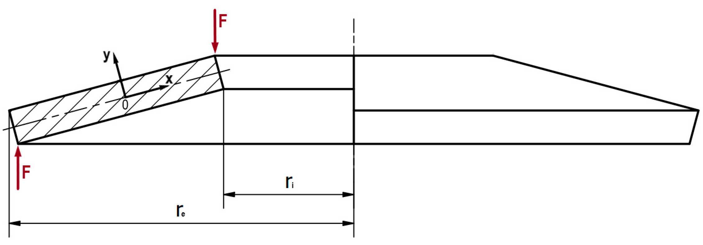
Belleville springs are categorized into two types based on their design: those without contact flats and those with contact flats. The formation of ground end surfaces is carried out in the case of springs with larger disc sizes. The construction of Belleville springs is shown in Figure 1.
The force-deflection characteristic F ( s ) of Belleville springs depends on the material’s properties and the spring’s geometric dimensions. In general, the characteristic curve exhibits a nonlinear, degressive behavior (softening spring), where the degree of nonlinearity is determined by the ratio of the spring’s initial height to its thickness h 0 / t [39]. Figure 2 illustrates the relative force F r e l , defined as the ratio of the force F ( s / h 0 ) to the force at full flattening F ( s / h 0 = 1 ) , where s represents the spring deflection. The diagram includes separate curves corresponding to different values of the cone height-to-thickness ratio h 0 / t . The graph highlights the importance of properly selecting the ratio h 0 / t in the context of a specific Belleville spring application. When the ratio satisfies h 0 / t 0.75 , the force-deflection curve is quasi-linear. In contrast, for h 0 / t 2 , the characteristic becomes bimodal, meaning that the same relative load value is obtained for two different deflection values of the Belleville spring. The DIN 2093 standard classifies Belleville springs into three series based on the h 0 / t ratio: series A, characterized by a h 0 / t ratio of approximately 0.4; series B, with a h 0 / t ratio of approximately 0.75; and series C, where the h 0 / t ratio is around 1.3.

3. Analytical Models

In this chapter, the key analytical methods used for the calculation of Belleville springs will be briefly discussed. The aim of this analysis is to preliminarily determine the application ranges of the methods being studied, which will be subjected to verification using FEM models in the subsequent chapter. The nomenclature and basic equations used throughout the paper are listed in the Nomenclature section.

3.1. Almen and László Method

The Almen–Laszlo method (A-L method) [23] is the most commonly used method for calculating Belleville springs. It assumes that the cross-section of the spring is perfectly rectangular, and as a result of the applied force, the cross-section of the spring does not deform but only rotates around point 0 (Figure 3). The Almen–Laszlo equation for force as a function of deformation (1) is derived from the equilibrium equation of moments of forces relative to the point 0.
F = 4 E t s 1 μ 2 α D e 2 h 0 s h 0 s 2 + t 2

3.2. Zheng Method

The energy method by Zheng et al. [32], unlike methods based on rigid body mechanics, is supposed to be more effective at determining the force and stresses in springs with a larger cone height h 0 and smaller disc thickness t . It assumes no deformation of the spring cross-section and neglects the stress in the axial direction σ z due to its minimal influence. The formula defining the spring characteristic, derived by Zheng in 2014, takes the following form (2):
F Z = 4 E s t 1 μ 2 D e 2 π α 1 , Z α 0 , Z h 0 s h 0 s 2 + t 2 .

3.3. DIN 2092 Method

To determine the characteristic and stress in a Belleville spring with contact flats, corrections to the Almen–Laszlo method, published by K. H. Muhr and P. Niepage in 1966 [30], can be applied. This method, in a slightly different form, is still referenced in the DIN 2092 standard. According to this standard, the characteristic of a Belleville spring with contact flats is determined using Equation (3):
F s = 4 E t s 1 μ 2 α D e 2 K 4 2 K 4 2 ( L 0 t ) s ( L 0 t ) s 2 + t 2 .

3.4. Giammarco Ferrari Method

In 2013, G. Ferrari, in his article [31], pointed out a critical issue with the DIN 2092 method, which results in a constant force value regardless of the ratio t / t (Figure 4). This means that this method can only correctly determine the force for Belleville springs in accordance with the DIN 2093 standard. The conditions are met only for a ratio close to t / t 0.925 (Figure 4). The DIN 2093 standard specifies the ratio t / t = 0.94 (for series A and B springs) and t / t = 0.96 (for series C springs). The formula derived by Ferrari (4) eliminates the issue of the constant force value for a varying t / t ratio. Figure 4 shows that the results from Ferrari’s method and the DIN 2092 method coincide for a ratio of t / t 0.925 .
F s = R d 4 E t s 1 μ 2 α D e 2 ( L 0 t ) s ( L 0 t ) s 2 + t 2

3.5. Leininger Method

The Almen–Laszlo and Zheng methods are based on the assumption that the spring’s cross-section is non-deformable and has an ideally rectangular shape. However, due to technological limitations, achieving perfectly sharp edges and straight angles is very difficult. Consequently, the assumptions made may lead to results that deviate from the actual behavior of the spring.
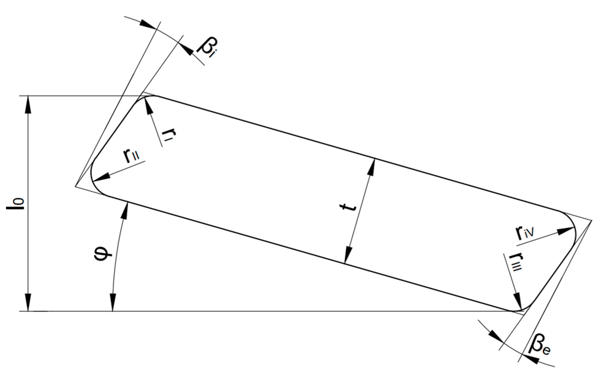
In the method proposed by Leininger et al. in 2022 [33], the authors highlight the potential inaccuracy of the obtained characteristics based on the simplifications used in the Almen–Laszlo method. In their method, they introduce parameters defining the radii of the corner roundings of the cross-section: rI, rII, rIII, and rIV. The deviation of the sides of the cross-section from a right angle is described by the introduction of the angles β i and β e (Figure 5). Additionally, a deflection-dependent lever arm V ψ ( s ) is introduced, depending on the deflection of the spring. By applying geometric changes and considering the deformation of the spring’s cross-section during loading, the modified Almen–Laszlo Equation (5) is obtained:
F A = 4 E s t 1 μ 2 D e 2 α h 0 s h 0 s 2 + t 2 R V ψ .
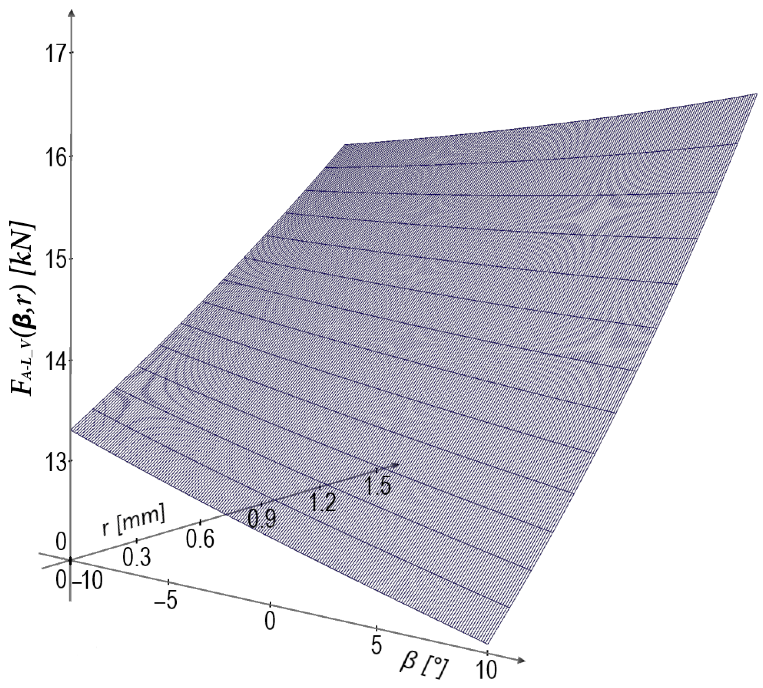
In Leininger’s equation, the deflection-dependent lever arm V ψ depends not only on the deflection of the springs but also on the radius of curvature r and the angle β . By comparing the results obtained using Leininger’s method and the Almen–Laszlo method, the change in force for full deflection of a specific spring conforming to DIN 2093 (excluding modifications in the section geometry) was investigated as a function of variations in the parameters r and angle β . As the radius increases to its maximum value of r = 0.5 t (half of the thickness), the force generated by the spring increases. When analyzing the effect of the angle of inclination of the cross-sectional walls, it was considered as follows: β i = β e = β . For the same values and signs of the angles, the cross-section forms a parallelogram. For negative values of the angle, higher force values are obtained, while as the angle increases, the force of the Belleville spring decreases. This accurately reflects the behavior of the spring, as for negative values of the angle β , the lever arm of the force decreases. However, it is worth noting that these changes are relatively small. It should be noted that for both the investigated curvature and angle inclination, the key factor was the introduction of the dynamically changing lever arm of the force. When using a constant lever arm, the differences between the values obtained from Leininger’s formulas and Almen–Laszlo’s formulas were several times smaller.
The influences of the angle β and radius r are illustrated in the graph in Figure 6, showing the force F A L _ V ( β , r ) . It can be observed that as the negative value of the angle β increases and the radius r increases, the force value of the spring increases.

3.6. Stacking Belleville Springs

Sometimes it is not possible to achieve the desired properties with a single disc spring, in which case these springs are arranged in assemblies. Belleville spring assemblies are classified into series, parallel, and combined arrangements (Figure 7).
Depending on the arrangement of the springs, different values of transmitted force and/or deflection of the assembly are obtained. This solution allows for the creation of different compliant arrangements with varying properties using the same springs [40]. Parallel assemblies typically consist of 2 to 4 Belleville springs, due to the increase in frictional forces with a higher number of springs. The use of Belleville springs stacked in series with more than 8 springs significantly reduces the fatigue life of the spring [30]. In a parallel arrangement, the stiffness and load capacity are increased, while in a series arrangement, the compliance and, therefore, the deflection of the spring stack are increased. The load dependencies of the assembly F n and the deflection s i for different configurations can be described by Equations (6) and (7), where i is the number of springs in series and n is the number of springs in parallel stack ( F is the force of a single spring, and s is the deflection of a single spring).
F n = n F
s i = i s

3.7. Stacking Belleville Springs to Obtain Progressive Characteristics

The load-deflection curves of a spring stack, like those of individual springs, are typically degressive. Progressive characteristics are achieved using a configuration with sequentially locking segments of springs in parallel (Figure 8a). Another method for obtaining a progressive characteristic is arranging springs of different thicknesses in a series stack (Figure 8b). The deflection of each segment is limited by using designated rings or stoppers.

3.8. Friction in Belleville Springs

Although no method accounting for friction in Belleville springs is included in the standards, the most frequently referenced one is that published by Muhr and Niepage in their book published in 1966 [30]. The formula for the force takes into account the number of springs in parallel n , the friction coefficient on the contact surface μ p , the friction between the conical surfaces of the springs μ t , and the cone angle φ . The force for the spring/stack of springs under loading can be determined using Formula (8) and under unloading using Formula (9).
F f n l o a d = n F 1 2 μ t n 1 δ t δ 1 D e 1 1 2 δ δ 1 t D e h 0 t 1 s h 0 + 1 t g φ + s s i g n h 0 t 1 s h 0 + 1 a r c t g μ p
F f n _ l o a d = n F 1 2 μ t n 1 δ t δ 1 D e 1 1 2 δ δ 1 t D e h 0 t 1 s h 0 + 1 t g φ + s s i g n h 0 t 1 s h 0 + 1 a r c t g μ p

4. FEA Verification

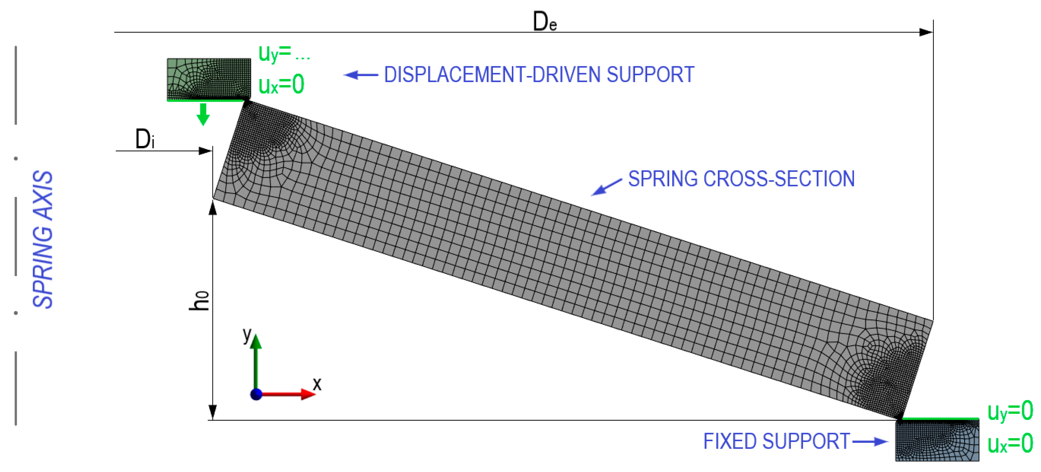
To verify the accuracy and application range of the analytical methods, as well as to determine the impact of friction on the operation of Belleville springs, FEA analyses were conducted. The model and its discretization are shown in Figure 9. Depending on the studied phenomenon, models with different cross-sectional geometries of the spring were used. In the models used to study the effect of friction and the applicability range of the springs, larger support surfaces were employed, ensuring that at the full displacement, the entire edges of the spring’s cross-section come into contact with the resistance surfaces (increasing the contact area, which influences the gradual reduction of the force lever arm and better reflects the actual working conditions of the spring). In the analyzed models considering frictional forces, appropriate friction coefficients were introduced between the specific surfaces. For the verification of analytical models for calculating springs with contact flats (e.g., Ferrari’s method [31]) or with non-rectangular cross-sections (Leininger’s method [33]), models with an appropriately modified spring geometry were used. The axial symmetry of the spring allows for modeling its cross-section and the use of 2D solid elements. Such axisymmetric models were employed to simplify the analysis and reduce the computational time while maintaining accuracy. In order to determine the force-displacement characteristics over the entire displacement range, the FEA analyses conducted were nonlinear. The Belleville spring is constrained by two discs, one of which undergoes a displacement by a specified distance, while the other restricts the spring’s displacement, simulating its support. Contact elements were introduced on the surfaces of the spring and discs.

Mesh Independence Study

Discretization plays a crucial role in obtaining accurate results in the finite element method (FEM). The geometry of the D6025425 ( D e = 60   m m , D i = 25.4   m m , t = 2.5   m m , and h 0 = 1.9   m m ) was modeled. To determine the appropriate mesh density for the Belleville spring FEM model, the results of the maximum stress (for deflection s = h 0 ) were compared depending on the mesh density. The difference between successive mesh refinements represents the error, which decreases as the number of finite elements increases (Figure 10). In the FEM model, the mesh was particularly refined in areas where the corners of the spring cross-section contact the supports (Figure 9). This is critical due to the contact between the spring cross-section and the supports, as well as the occurrence of maximum stresses in the spring. This local mesh refinement was also adjusted proportionally to the change in the global mesh density.
The study was conducted for five different mesh density values, ranging from 3728 to 6594 finite elements. The difference between the maximum and minimum stress values was less than 0.35%. This indicates that the mesh density has a minimal impact on the results for this specific problem. This outcome is due to the use of a simple geometric model and the application of 2D elements, which lead to smaller numerical errors compared to 3D elements. In subsequent FEM models, the mesh density will not be lower than that of the model with the highest density examined.

5. Results

This chapter present the results of FEM model analyses, enabling a deeper understanding of the validity and effectiveness of the previously discussed analytical methods. A comparison of traditional, normatively established methods with new approaches, followed by their verification using FEM models, will allow for determining the scope of applications of each method.

5.1. Analysis of the Applicability Range of Belleville Springs

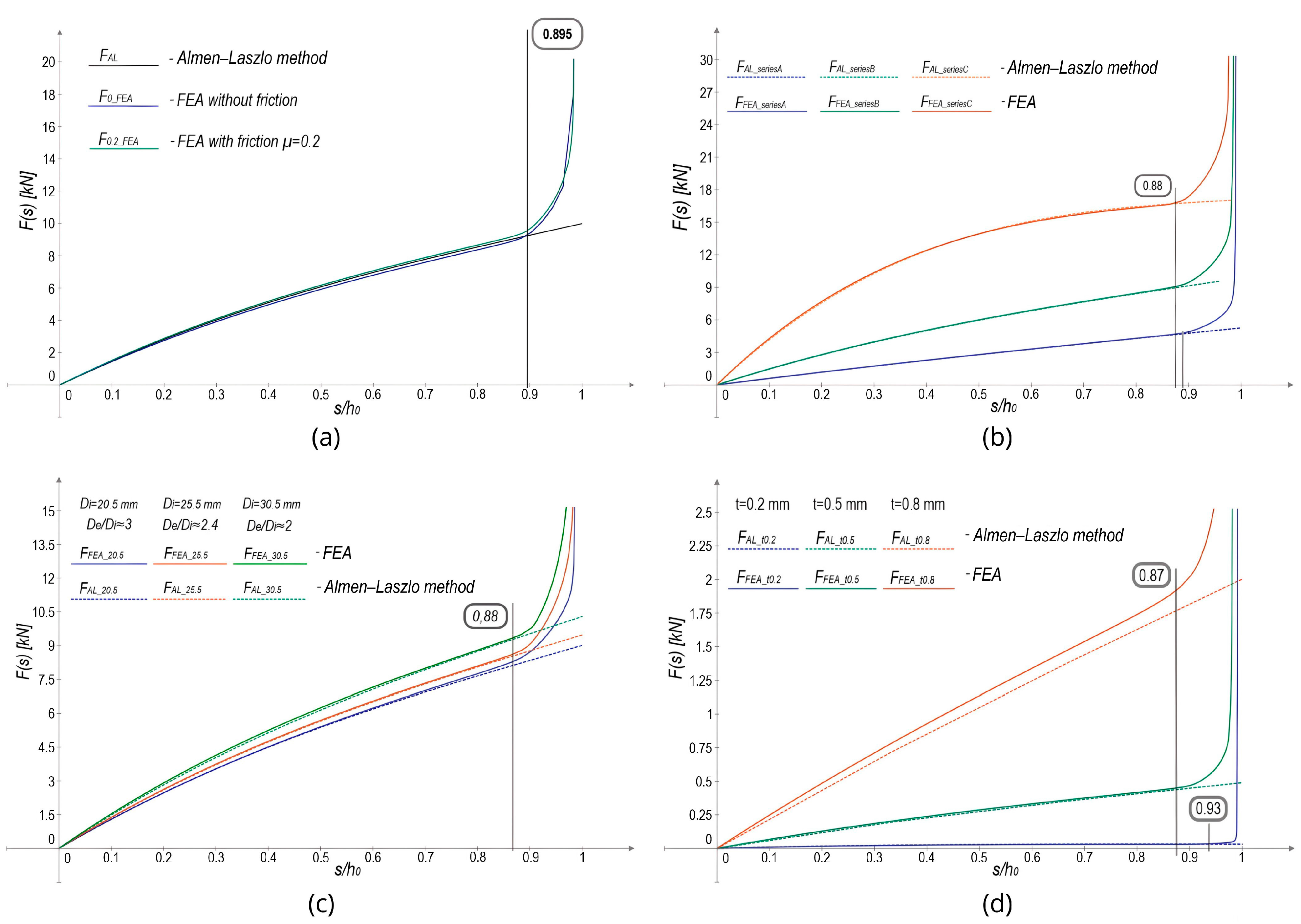
According to the DIN 2093 standard [22], typical Belleville springs should be used up to a deflection of s = 0.75 h 0 . This limitation is attributed to the sudden increase in force at the final stage of deflection. To verify the specified applicability range and identify the reasons for discrepancies in force values compared to analytical methods, FEA analyses were conducted on models with various modified spring parameters. The range of degressive characteristics was examined due to the presence of friction (Figure 11a), the ratio h 0 / t in accordance with Belleville spring series specified in DIN 2092 (Figure 11b), the ratio of the outer diameter to inner diameter D e / D i (Figure 11c), and the disc thickness t (Figure 11d).

5.2. Comparative Analysis of the Zheng Method and the Almen–Laszlo Method

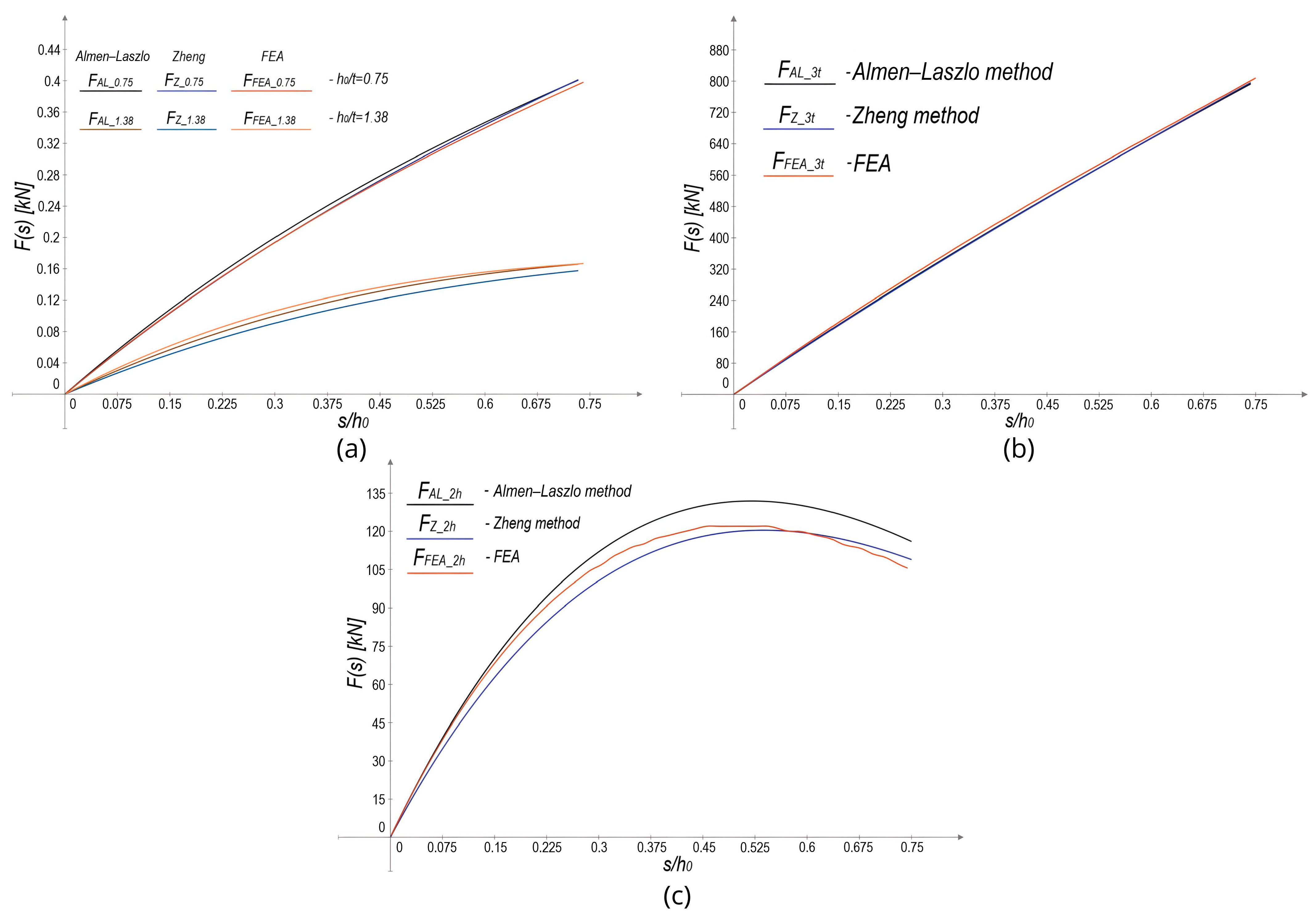
In the study by Zheng et al. [32], the authors initially state that their objective is to obtain more accurate results for springs with large thickness and cone heights. To verify the accuracy of Zheng’s method, analyses were conducted comparing the results of FEA, the Almen–Laszlo method, and Zheng’s method for springs with a varying cone height h 0 and disc thickness t . The analysis included springs with an h 0 / t ratio compliant with DIN 2092 and DIN 2093 standards (Figure 12a), as well as springs with a non-standard, increased ratio (Figure 12b, c).

5.3. Verification of Ferrari’s Method for Belleville Springs with Contact Flats

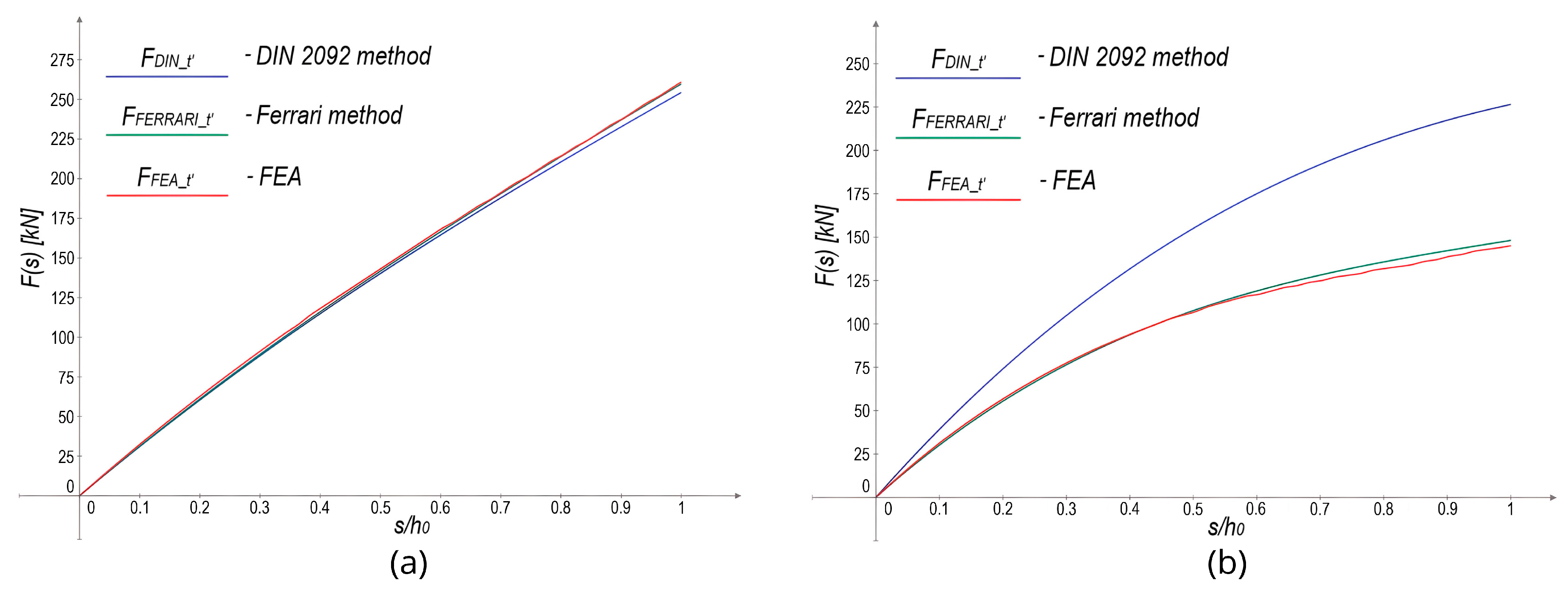
The primary reason for Giammarco Ferrari’s development of a new analytical method [31] was the lack of responsiveness of the DIN 2092 method to changes in the ratio of the reduced thickness to the nominal thickness t t / t of a Belleville spring. This makes the method provided in the DIN 2092 standard valid only for springs with geometries conforming to the DIN 2093 standard. Such springs are characterized by a ratio of t / t 0.94 . To investigate the characteristics of Belleville springs with contact flats, an FEA was conducted for the D2009212 spring ( D e = 200 mm, D i = 92 mm, t = 11.25 mm) compliant with the DIN 2093 standard (Figure 13a), as well as for a variant with a decreased thickness of t = 8   m m (Figure 13b). This modification results in a non-standard ratio of t / t = 2 / 3 .

5.4. Verification of Leininger’s Method

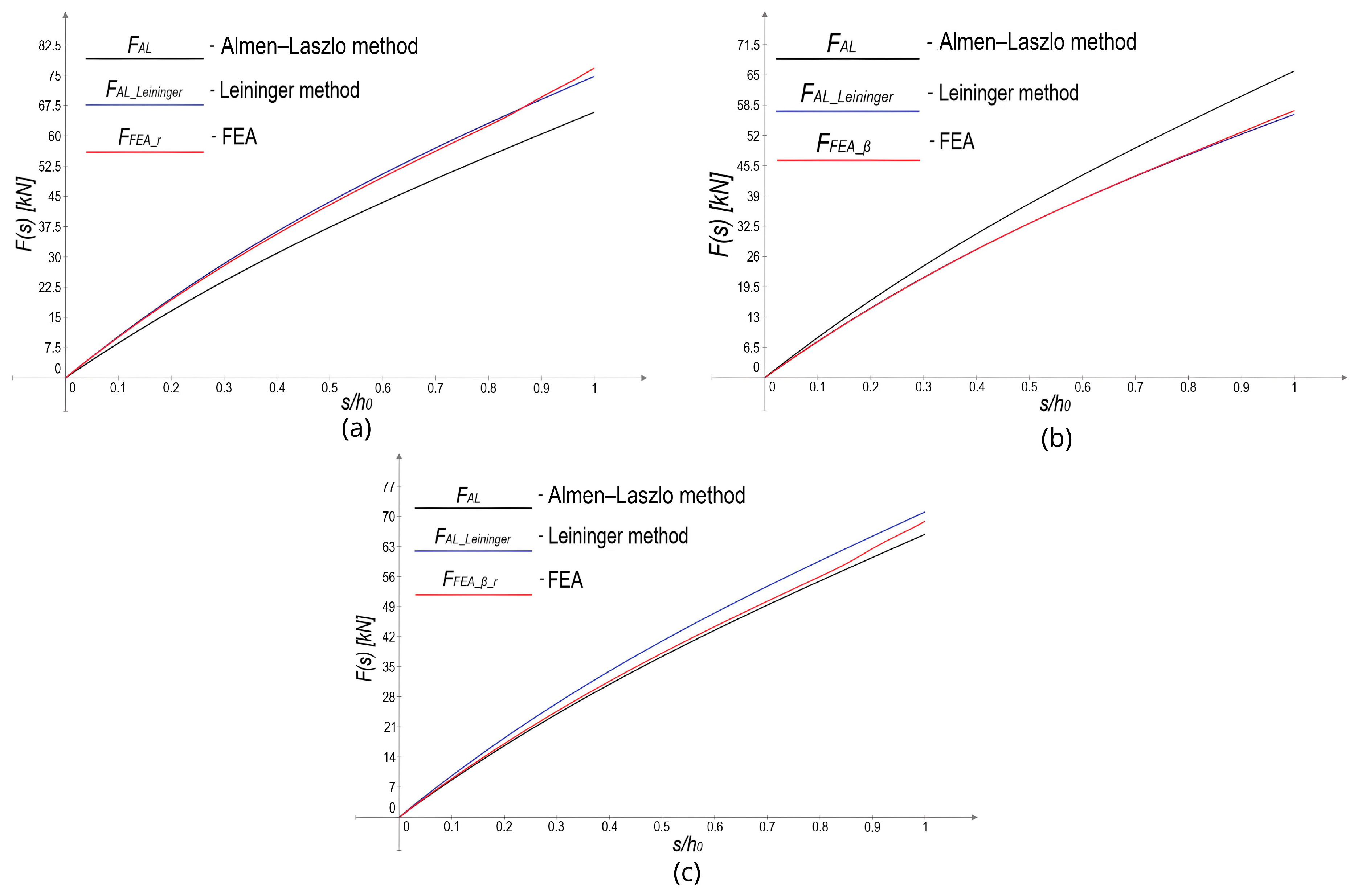
To verify Leininger’s geometry reduction method [33], modifications were introduced to the model of the D125646 spring ( D e = 125 mm, D i = 64   m m and t = 6   m m ): curved edges with a radius r = 1.5   m m (Figure 14a), sidewall deviation from perpendicularity by an angle β = 30 ° (Figure 14b), and a combination of radius r = 0.5   m m with an angle β = 5 ° (Figure 14c). According to Leininger’s method, the reduced geometry and the deflection-dependent lever arm were applied to the A-L method.

5.5. Effect of Friction on Disc Springs

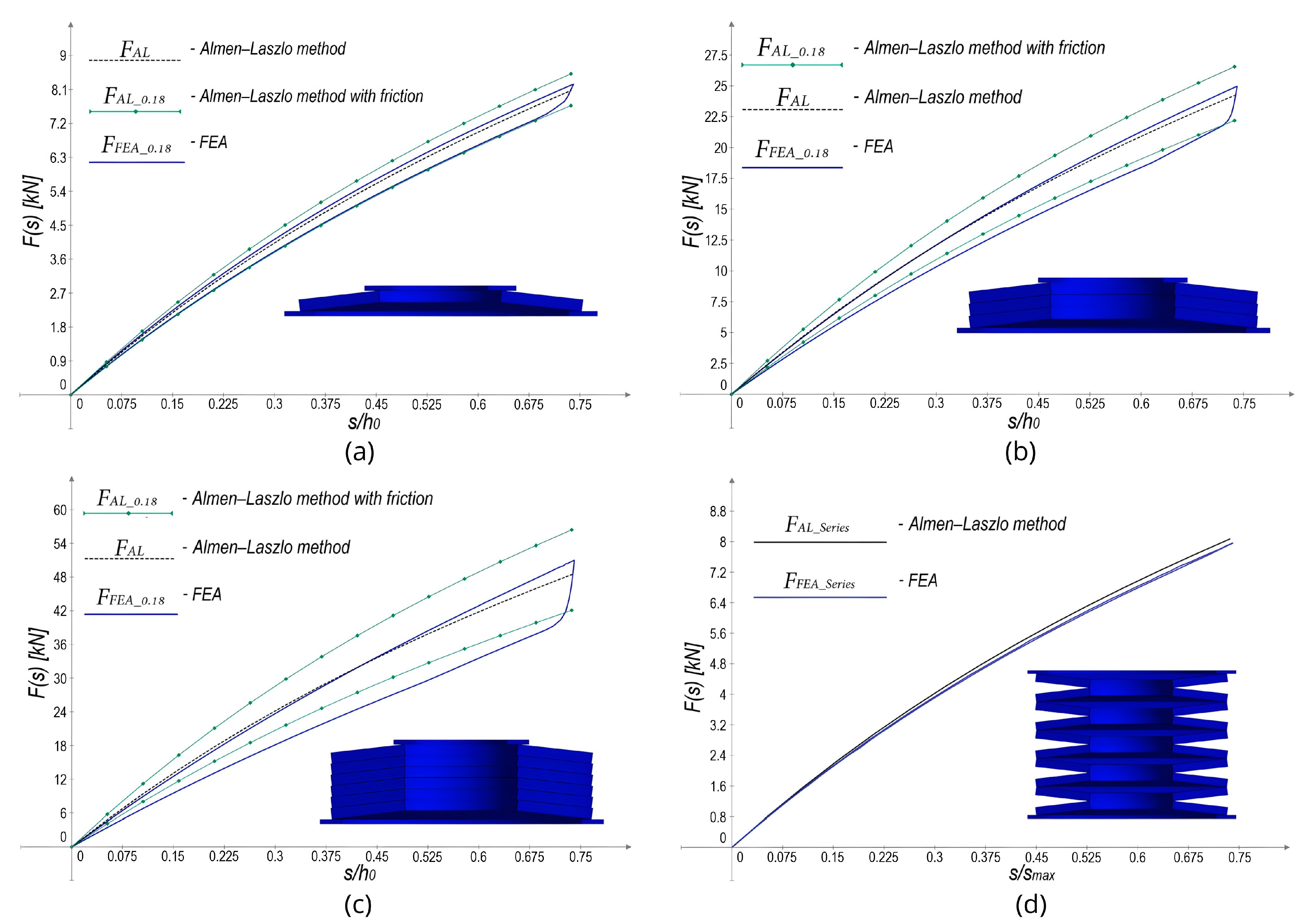
To investigate the effect of friction on a single spring and Belleville spring stacks, analyses were conducted using the model of the spring D6025525 ( D e = 60   m m , D i = 25.5   m m , t = 2.5   m m ). In the FEA model, a friction coefficient of μ p = 0.18 was assumed for the contact between the springs and the supports, while a coefficient of μ t = 0.13 was used for the contact between the Belleville springs in stacks. Analyses were carried out for a single spring (Figure 15a), for three springs arranged in parallel (Figure 15b), for six springs in parallel, which exceeds the recommendations of the DIN 2092 and DIN 2093 standards (Figure 15c), and for springs stacked in series (Figure 15d). The results obtained from the FEM model were compared with the A-L method, which does not consider friction forces, and the method published by Muhr and Niepage [30], where the same values of friction coefficients as in the FEM model were applied.

6. Discussion

The results obtained by comparing analytical methods with FEM models allowed for the formulation of conclusions and determination of the each method’s scope of applicability.
The results presented in Section 5.1 allow for the verification of the values indicated by the DIN 2092 and DIN 2093 standards, according to which disc springs should be used within the deflection range up to s = 0.75 h 0 . The transitions from the degressive to progressive load-deflection curve always occurred beyond the point specified by the standards. From the analyzed cases, it can be concluded that the actual applicability range of the spring and the validity of the characteristics obtained by the Almen–Laszlo method are greater, ending at a deflection of approximately s 0.88 h 0 . Moreover, apart from one case, no significant differences in the deflection range were observed depending on the changing working parameters and geometric parameters of the spring. The only case where a noticeable change occurred was the model of the spring with a small disc thickness (Figure 11d), where the largest deflection range with a degressive characteristic was obtained, reaching s 0.93 h 0 . The transition from edge contact to surface contact is the reason for the change in the spring’s characteristic. Thus, in the case of a spring with lower stiffness, a larger deformation of the cross-section during deflection results in a longer duration of edge contact between the spring and the base. The deflection range specified by the standards appears to be overly conservative, probably due to the consideration of a safety factor and the increase in the spring’s fatigue strength. It should be noted, however, that some industry references suggest a deflection range up to s = 0.85 h 0 , which approximately aligns with the obtained results. In conclusion, it should be stated that applied changes in geometry do not significantly affect the applicability range of the Belleville spring, and the range specified by the standards is unequivocally safe.
The results presented in Section 5.2 indicate that the Zheng method does not demonstrate greater accuracy compared to the Almen–Laszlo method when solely increasing the thickness (Figure 12b) or the cone height of the spring. Improved results from this method are only noticeable when springs exhibit a higher ratio of these parameters h 0 / t (Figure 12c). Therefore, the use of Zheng’s method is justified for springs from series C (Figure 12a), where the ratio h 0 / t is higher, as well as for non-standard springs, where the difference between the A-L and Zheng methods becomes clearly noticeable (Figure 12c). Thus, it can be concluded that Zheng’s method is more suitable for accurately determining the force for springs with a higher h 0 / t ratio. This method would be particularly useful for non-standard springs with strongly non-linear F ( s ) characteristics, where this ratio exceeds the value typical for springs from series C (s / h 0 > 1.3 ).
In verifying Ferrari’s method in Section 5.3, the primary reason for its development was examined, namely, the creation of a method that enables the calculation of Belleville springs with contact flats and a non-standard ratio of reduced thickness to normal thickness t / t . As expected, for a spring compliant with the DIN 2093 standard, both the method specified by the standards and Ferrari’s method closely matched the results obtained from the FEM model across almost the entire range (Figure 13a). In the case of a change in spring thickness, resulting in a non-standard ratio of t / t = 2 / 3 the force value calculated according to DIN 2092 for a deflection of s = 0.75 h 0 remains the same as for the spring with its original thickness. Only the shape of the force-deflection curve is altered (Figure 13b). This clearly represents an incorrect depiction of the load–deformation relationship. For such a spring, the Ferrari method yields results that align with those obtained from the FEM model across the entire range (Figure 13b). Therefore, it can be concluded that the Ferrari method successfully fulfills the objective set by its author, enabling the calculation of characteristics for non-standard springs with a ratio different from that specified in DIN 2093.
The results presented in Section 5.4, which were obtained from FEM models for springs with non-rectangular cross-sections to assess the validity of the Leininger method, have identified cases in which this method provides more accurate results than the Almen–Laszlo method. The approach proposed by Leininger for accounting for cross-sectional geometry imperfections yields results that closely correspond to the entire range of FEM outcomes for springs with significantly non-rectangular cross-sections (Figure 14a, b). In practice, for standard Belleville springs, the radius r and angle β are significantly smaller, and their minor values do not substantially affect the deviation of the F ( s ) characteristics from those obtained using the conventional Almen–Laszlo method. The characteristics shown in Figure 14c illustrate that for such small values of radius r and angle β , the results obtained using the standard A-L method are closer to those derived from the FEA model, which brings into question the validity of using Leininger’s method for standard Belleville springs compliant with DIN 2092 and DIN 2093.
The graphs presented in Section 5.5, illustrating the effect of friction on the performance of Belleville springs, show that the A-L method with the modification published by Muhr and Niepage overestimates the force during loading of a single spring, while during unloading, it almost perfectly matches the results obtained from the FEM model (Figure 15a). In the case of springs stacked in parallel, the results derived from the analytical method exhibit a lower degree of alignment with the values obtained from the FEM model (Figure 15b, c). It can be observed that the force obtained from the FEM model during loading are only slightly higher than those obtained using the classical Almen–Laszlo method. Thus, it can be concluded that friction plays a more significant role during unloading, whereas when determining the maximum force, the classical A-L method provides results that are only marginally lower than the actual values. The friction forces for springs arranged in series were found to have a minimal impact on the characteristic behavior of the stack (Figure 15d).

7. Algorithm for Selecting the Calculation Method for a Belleville Spring

As a result of the verification of various analytical methods, a flowchart (Figure 16) was developed to facilitate the selection of the appropriate analytical method for a spring with specified properties. Through an analysis using FEM models, both the advantages and disadvantages of the different methods were revealed, which enabled the identification of their respective application areas.

Summary Description of the Methods and the Scope of Their Applicability

(I)
Almen–Laszlo Method
  • Description: A widely used analytical method for calculating the force-deformation characteristics of Belleville springs.
  • Applicability: Suitable for standard disc springs with a rectangular cross-section without contact flats and when the spring geometry adheres to typical industrial standards (e.g., DIN 2092, DIN 2093).
(II)
Zheng Method
  • Description: An alternative analytical method that improves the accuracy for springs without contact flats with a higher ratio of cone height to thickness h 0 / t .
  • Applicability: Best for non-standard disc springs, those exhibiting higher non-linearity and greater h 0 / t ratio, which exceeds the ratio for the springs from series C according to DIN 2093 ( h 0 / t > 1.3 ) .
(III)
Leininger Method
  • Description: A method introducing reduced values to the Almen–Laszlo or Zheng method to account for curved edges and non-rectangular cross-sectional shape. For Belleville springs without contact flats.
  • Applicability: Most accurate for springs with highly non-rectangular cross-sections. For small values of the radius r and the angle of deviation β , this method proved to yield less accurate results compared to the Almen–Laszlo method. Therefore, its use is recommended only for high values of r and β , such as r t / 6 and β 15 ° .
(IV)
DIN 2092 Method for Springs with Contact Flats
  • Description: The modified Almen–Laszlo method enabling the determination of the characteristic for standard Belleville springs with contact flats, where the ratio t / t adheres to the specifications outlined in the DIN 2093 standard.
  • Applicability: This method yields inaccurate results for Belleville springs with a non-standard ratio t / t 0.92 , with deviations increasing as the difference from this ratio becomes larger.
(V)
Giammarco Ferrari Method
  • Description: A method for calculating Belleville springs with contact flats, where the accuracy is not dependent on the t / t ratio.
  • Applicability: The method provides accurate force calculations for non-standard t / t ratios, with the results closely matching the DIN 2092 method for t / t > 0.92 .

8. Development of a Calculation Method for Belleville Spring Assemblies with a Quasi-Progressive Characteristic

In the available literature, no explicit formula for calculating the characteristics of assemblies with limiters has been identified. Therefore, a computational procedure was developed for spring stacks arranged in a way that facilitates the generation of quasi-progressive characteristics.
To obtain a quasi-progressive characteristic for Belleville springs, creating stacks of springs arranged in series and in parallel with varying numbers of springs in each segment is necessary. To prevent each segment from bending in the opposite direction during subsequent stages of deflection, appropriate limiters are used between the segments. The model selected for analytical calculations and the FEM analysis consisted of m = 3 segments made up of Belleville springs D6025425 ( D e = 60   m m , D i = 25.4   m m , t = 2.5   m m and h 0 = 1.9   m m ), with its arrangement presented in Figure 17. The new nomenclature and formulas specific to the method presented in this section are listed in the Nomenclature section.

8.1. General Formula for the Characteristic of a Belleville Spring Assembly Consisting of Identical Springs Arranged in Segments Separated by Limiters

The application of analytical method is presented in Appendix A.1. Due to discrepancies between the results obtained from this method and those from the FEM model, corrections were introduced, taking into account the deflection ranges of individual segments at specific stages as determined by the FEM model. The process of applying the corrected method is shown in Appendix A.2. The differences between the uncorrected and corrected methods are presented in Section 8.2 and Section 8.3.
The derived method can be expressed in the general form presented below. This method applies to stacks consisting of Belleville springs with the same dimensions, separated by limiters that create segments. The corrected parameters were determined only for a specific spring and a particular configuration of the assembly (Figure 17). For the uncorrected method, the procedure follows point (Ia), while for the corrected method, it follows point (Ib). Point (II), which involves substituting the determined parameters into the general equation, is common to both methods.
(Ia)
Analytical method (as shown in Appendix A.1)
The equations listed in Table 1 were utilized, which have been derived and whose application process is thoroughly presented in Appendix A.1.
(Ib)
The method with parameters corrected based on the FEM model (as shown in Appendix A.2)
For the corrected method, the parameters should be taken from the appropriate table for a specific spring and assembly configuration, such as Table 2, which was created for the calculated example (Appendix A.2). It should be noted that the given displacement distribution is valid only for the specific stack. For other assemblies, the parameters s m i m a x and s m w m i will differ (as shown in Section 8.3). In order to apply this method to a different case, it would be necessary to determine the parameters for other possible configurations of assemblies and spring dimensions. Alternatively, one could seek mathematical relationships that universally link these parameters.
(II)
Substituting the determined coefficients into the general formula for force in the stack
The force for a given deflection stage is calculated as follows:
F s m i = F s m i 1 m a x + [ j = m i j = m n j · 4 E t l j m i ( s m i j = 0 j = m i 1 s m j ) 1 μ 2 α D e 2 [ h 0 l j m i ( s m i j = 0 j = m i 1 s m j ) ( h 0 l j m i ( s m i j = 0 j = m i 1 s m j ) 2 ) + t 2 ] ] / m .

8.2. Comparison of the Developed Analytical Method with the FEA Results

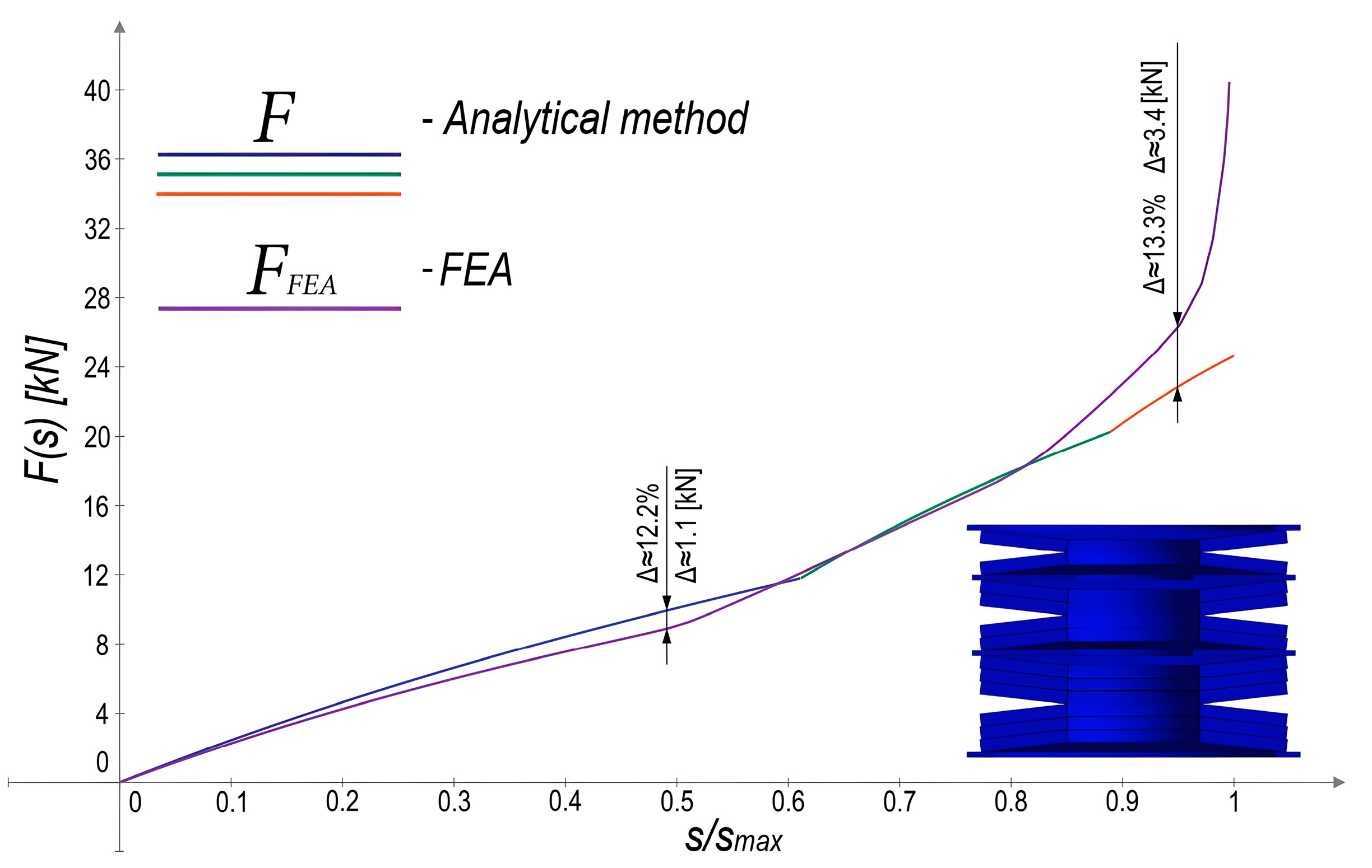
A study was conducted for the full deflection of the assembly, excluding friction. A comparison of the obtained results is shown in Figure 18. The first stage of deflection is marked in navy blue, the second in green, and the third in red (each stage corresponding to the complete flattening of individual segments). The analytical results exhibit discrepancies when compared to those derived from the FEM model. Notably, the points of inflection on the graph do not align with the analytically calculated values, suggesting that the deflection intervals for stages I, II, and III differ from those determined in Appendix A.1. These discrepancies may be attributed to the varying lever arm of the applied force and the points of contact between the springs, other springs, the limiters, and the supports. However, despite these differences, this method for this particular spring at a deflection of s = 0.75 s m a x yielded an almost identical value to the FEM model. The discrepancy between the analytical method and the FEM model was about 12.2% at a deflection of approximately s 0.49 s m a x and 13.3% at s 0.95 s m a x . Beyond a deflection of s = 0.95 s m a x , the stack’s characteristic transitions to a strongly progressive behavior. In Appendix A.2, the parameters were adjusted based on the results obtained from the FEM model. The results of the corrected method compared with the FEM models are presented in Section 8.3.

8.3. Adjustment of Parameters for the Developed Analytical Method Based on the Obtained FEA Results

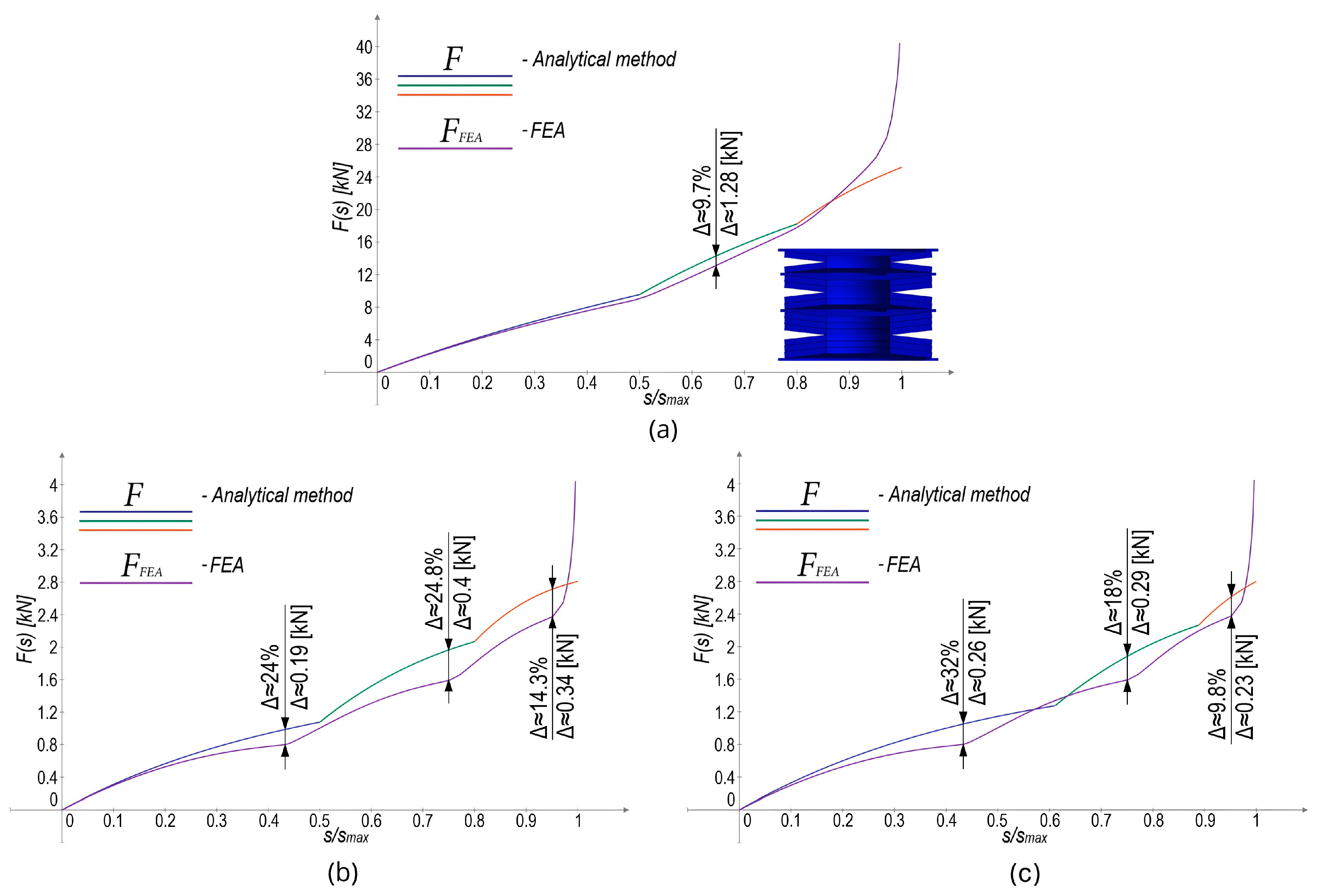
The parameter correction presented in Appendix A.2 involved adjusting the deflection ranges of individual deflection stages based on the results obtained from the FEM model. The comparison of the characteristic obtained using the corrected formula with the FEA results is shown in Figure 19a. After the correction, the points at which individual segments are excluded align with the FEA results. The force value is slightly higher up to a deflection of s = 0.87 s m a x . This minor overestimation of the force within the applicable range may be attributed to deformations in the cross-sections of the washers and limiters, as well as changes in the support points. It can be concluded that the results obtained with the developed algorithm align with the FEA model’s results with satisfactory accuracy. However, the values for the exclusions and deflections of individual segments obtained in this manner are correct only for the D6025425 spring. For a different spring (D2814208), the method with correction using the coefficients determined for the D6025425 spring (Figure 19b) and without correction (Figure 19c) do not yield the correct characteristic for the spring assembly. Interestingly, the uncorrected method (Figure 19c) aligns more closely with the FEM model over a broader range than the corrected version (Figure 19b) applied to a different spring. This means that the corrected parameters, i.e., the deflection ranges at each stage, differ significantly between different springs. Despite noticeable deviations at specific points, the uncorrected method captures the overall stack behavior with a certain degree of accuracy. This all indicates that applying the corrected method requires determining coefficients depending on the type of spring and arrangement of the stack. Similar to the D6025425 springs (Figure 18 and Figure 19a), the D2814208 springs (Figure 19b, c) arranged in such assembly remain applicable up to a deflection of s = 0.95 s m a x .

8.4. Conclusions Regarding the Developed Method for Calculating Belleville Spring Assemblies with a Quasi-Progressive Characteristic

The methods for obtaining a quasi-progressive characteristic using Belleville springs have been presented. The derived corrected method allows for determining the force of a stack composed as shown. The procedure for determining the deflections of individual segments using the FEM model can be useful for developing a general formula for various configurations of the stack and different spring geometries. To determine the deflection ranges of each segments at different stages, developing a table containing the coefficients presented in this work is necessary. These values should correspond to different types of disc springs and their configurations, according to the adopted algorithm. This would imply modeling these spring stacks in the FEM environment and determining the appropriate displacement values for each case or identifying specific dependencies of these coefficients for varying spring dimensions and configurations. Further research in this area is recommended to develop a universal method for calculating the characteristics of quasi-progressive spring stacks. The uncorrected method broadly reflects the behavior of the specified spring stack. However, deviations from the results obtained from FEM models raise doubts about its applicability.

9. Conclusions

This study has presented a comprehensive comparison of analytical methods with FEM models to enhance the understanding of their applicability. Both classical approaches, such as the Almen–Laszlo method and methods outlined in the DIN 2092 standard, as well as more recent ones, including Zheng’s energy method, Ferrari’s method, and Leininger’s approach, have been analyzed. Areas of convergence between the results obtained from analytical methods and FEM models have been identified, enabling the development of an algorithm for selecting an appropriate calculation method for a given type of Belleville spring. Furthermore, the actual application range of Belleville springs was examined, considering their construction and operating conditions. An analysis of the influence of friction forces was also conducted for a single spring and springs stacked in parallel and in series, highlighting the differences between the hysteresis observed in FEM models and the results obtained from analytical formulas. A lack of analytical methods for calculating the characteristics of Belleville spring stacks with quasi-progressive behavior was identified, and an algorithm was proposed to enable their determination. The proposed method was validated using a specific case study, enabling an assessment of its accuracy. Furthermore, future research directions were identified to develop a universal computational approach for Belleville spring assemblies with quasi-progressive characteristics, accounting for various configurations and different types of disc springs.

Author Contributions

Conceptualization, J.K.; methodology, J.K.; validation, J.K.; formal analysis, J.K.; investigation, J.K.; resources, M.W. and J.K.; data curation, J.K.; writing—original draft preparation, J.K.; writing—review and editing, J.K. and M.W.; visualization, J.K.; supervision, M.W. All authors have read and agreed to the published version of the manuscript.

Funding

This research received no external funding.

Data Availability Statement

The data are contained within the article.

Conflicts of Interest

The authors declare no conflicts of interest.

Nomenclature

D e Outside diameter [mm]
D e Reduced outside diameter [mm]
D i Inside diameter [mm]
D i Reduced inside diameter [mm]
t Disc thickness [mm]
t Reduced disc thickness [mm]
h 0 Initial cone height [mm]
h 0 Reduced initial cone height [mm]
L 0 Free overall height of spring in its initial position [mm]
L 0 Reduced free overall height of spring in its initial position [mm]
s Spring deflection [mm]
φ Spring cone angle [°]
E Young’s modulus [MPa]
μ Poisson’s ratio [-]
δ Ratio of the outside diameter to the inside diameter of the spring [-]
n Number of springs in parallel [-]
i Number of springs in series [-]
μ t Friction coefficient between the conical surfaces of the springs [-]
μ p Friction coefficient on the contact surface [-]
D e Modified outside diameter according to Leininger’s method [33] [mm]
h 0 Modified initial cone height according to Leininger’s method [33] [mm]
α Modified coefficient according to Leininger’s method [33] [-]
R Modified radius of a spring according to Leininger’s method [33] [mm]
V ψ Deflection-dependent lever arm according to Leininger’s method [33][mm]
Nomenclature specific for the developed method
m Number of all segments [-]
m i Segment number [-]
m w   Number of active segments undergoing deformation [-]
s m i m a x Maximum deflection in a given deflection range [mm]
s m a x _ r e a l Maximum real deflection of the stack [mm]
s m a x Maximum calculated deflection of the stack [mm]
k i Parameter defining the deflection as a fraction of the maximum deflection at each stage [-]
s i m j Deflection of individual segments at each stage [mm]
l i m j Parameter defining the deflection as a fraction of the maximum deflection of a given segment at each stage [-]
s m i Deflection range [mm]
Basic Equations
δ = D e D i   [-]
α = 1 π δ 1 δ 2 δ + 1 δ 1 2 l n   δ   [-]
α 0 , Z = 1 μ 2 6 δ 1 2 ln δ 1 4 δ 2 1 δ 2 δ 2 1 ln δ 2 [-]
α 1 , Z = 1 6 δ δ 1 2 ln δ [-]
K 4 = C 1 2 + C 1 2 2 + C 2 [-]
C 1 = t t 2 L 0 4 t t t + 3 4 5 L 0 8 t t t + 3 8 [-]
C 2 = C 1 t t 3 5 32 L 0 t 1 2 + 1 [-]
r a = b D e [-]
D e = D e 2 D e r a + 2 [ t D e r a sin φ sin φ ] [mm]
D i = D i + 2 D e r a + 2 [ t D e r a sin φ sin α φ ] [mm]
R d = D e D i D e D i [-]
Basic equations specific for the developed method
m w = m i ,   m i + 1 ,     , m [-]
s m a x _ r e a l   = i h 0 [mm]
s m a x = m h 0 [mm]
j = 0 j = m i 1 s m j s m i j = 0 j = m i 1 s m j + s m i m a x [mm]

Appendix A. The Process of Developing a New Computational Method for Belleville Spring Assemblies with a Quasi-Progressive Characteristic

Appendix A.1. Development of an Analytical Method

The calculations were performed for the spring stack shown in Figure 17. Due to the m = 3 segments, the computational considerations were divided into three deflection ranges corresponding to the flattening and, consequently, the disengagement of individual segments. It should be noted that for such an assembly, the maximum deflection depend on the number of springs arranged in series (A1):
s m a x _ r e a l = i h 0 .
However, since springs arranged in parallel exhibit the same characteristic shape, with only the force range changing, in the case of a model divided into m = 3 segments, the maximum deflection considered in the calculations is three times the height of the cone of a single spring (A2). This leads to the equation for the maximum real deflection (A3).
s m a x = m h 0
s m a x _ r e a l = i s m a x m
As a consequence, in the formula for force, the expression corresponding to the force increment must be divided by the number of segments m . To present the calculation procedure, a stack consisting of three segments separated by two limiters was chosen as an example (Figure 17). The calculation scheme for this model is provided below (Equations (A4)–(A21)), where the analysis has been divided into individual stages of the assembly’s deflection.
(I) 
0 s 1 s 1 m a x , n 1 = 1 ,
The initial stage occurs when all the springs undergo deflection. The end of this stage is reached when the first segment m 1 completely flattens, at which point it is excluded from further stages and no longer participates in the deflection process (springs are pressed against the first limiter). In the first step, the maximum deflection for this stage must be calculated as follows:
s 1 m a x = 1 n 1 1 m s m a x + 1 n 2 1 m s m a x + 1 n 3 1 m s m a x = 1 1 1 3 s m a x + 1 2 1 3 s m a x + 1 3 1 3 s m a x = 11 18 s m a x ,
where
s 1 m a x = k 1 s m a x .
Thus, the parameter k is obtained
k 1 = 11 18 .
Since the stiffness of a spring depends on the number of springs stacked in parallel n , this will directly result in different deflections of the individual segments. The greater the number of springs in parallel, the smaller the deflection of each segment. Therefore, calculating the deflection of the individual segments within the assembly is necessary:
s 1 m 1 = s 1 m a x k 1 1 m 1 n 1 = 18 11 s 1 m a x 1 3 1 1 = 6 11 s 1 m a x ,
s 1 m 2 = s 1 m a x k 1 1 m 1 n 2 = 18 11 s 1 m a x 1 3 1 2 = 3 11 s 1 m a x ,
s 1 m 3 = s 1 m a x k 1 1 m 1 n 3 = 18 11 s 1 m a x 1 3 1 3 = 2 11 s 1 m a x .
By determining this, the formula for the force in a given deflection range is obtained as follows:
F s 1 = [ n 1 · 4 E t s 1 m 1 1 μ 2 α D e 2 h 0 s 1 h 0 s 1 2 + t 2 + n 2 · 4 E t s 1 m 2 1 μ 2 α D e 2 h 0 s 1 h 0 s 1 2 + t 2 + n 2 · 4 E t s 1 m 3 1 μ 2 α D e 2 h 0 s 1 h 0 s 1 2 + t 2 ] / m .
(II) 
s 1 m a x s 2 s 1 m a x + s 2 m a x ,  n 2 = 2
For this stage, the final deflection occurs when the second segment m 2 has completely flattened. There is no further deflection of the first segment. Since the second segment has already been deformed in the first stage, its total deflection in this stage will be reduced by that amount. The total maximum deflection for this range will be
s 2 m a x = 1 n 2 1 m s m a x + 1 n 3 1 m s m a x = 1 2 1 3 s m a x + 1 3 1 3 s m a x = 5 18 s m a x ,
where
s 2 m a x = k 2 s m a x .
Thus, the parameter k is obtained as follows:
k 2 = 5 18 .
The deflection of two segments will be
s 2 m 2 = s 2 m a x k 2 1 m 1 n 2 = 18 5 s 2 m a x 1 3 1 2 = 3 5 s 2 m a x ,
s 2 m 3 = s 2 m a x k 2 1 m 1 n 3 = 18 5 s 2 m a x 1 3 1 3 = 2 5 s 2 m a x ,
where
s 2 m 2 = l 2 m 2 s 2 m a x ,
s 2 m 3 = l 3 m 3 s 2 m a x .
Thus, the parameters l are obtained as follows:
l 2 m 2 = 3 5 ,
l 3 m 2 = 2 5 .
By adding the force obtained in the previous step for the end of the displacement range s 1 = s 1 m a x , the formula for the force in the second stage (A16) is derived. Additionally, the graph is shifted to the right by the value s 1 m a x . Thus, the formula for the force in this range is obtained as follows:
F s 2 = F s 1 = s 1 m a x + [ n 2 · 4 E t l 2 m 2 ( s 2 s 1 m a x ) 1 μ 2 α D e 2 [ h 0 l 2 ( s 2 s 1 m a x ) h 0 l 2 m 2 ( s 2 s 1 m a x ) 2 + t 2 ] + n 3 · 4 E t l 3 m 2 ( s 2 s 1 m a x ) 1 μ 2 α D e 2 h 0 l 3 ( s 2 s 1 m a x ) h 0 l 3 m 2 ( s 2 s 1 m a x ) 2 + t 2 ] / m .
(III) 
s 1 m a x + s 2 m a x s 2 s 2 m a x + s 3 m a x ,  n 3 = 3
For this stage, only the last segment undergoes displacement. Its displacement will be
s 3 m a x = 1 n 3 1 m s m a x = 1 3 1 3 s m a x = 1 9 s m a x ,
where
s 3 m a x = k 3 s m a x .
Thus, the parameter k is obtained as follows:
k 3 = 1 9 .
The displacement of the last segment will be
s 3 m 3 = s 3 m a x k 3 1 m 1 n 3 = 9 1 s 3 m a x 1 3 1 3 = s 3 m a x ,
where
s 2 m 3 = l 3 m 3 s 2 m a x .
Thus, the parameter l is obtained as follows:
l 3 m 3 = 2 11 .
The force in the final stage of displacement is expressed by the following formula:
F s 3 = F s 2 = s 1 m a x + s 2 m a x + [ n 3 · 4 E t l 3 m 3 ( s 3 s 1 m a x + s 2 m a x 1 μ 2 α D e 2 [ h 0 l 3 m 3 ( s 3 ( s 1 m a x + s 2 m a x ) ) ( h 0 l 3 m 3 ( s 3 s 1 m a x + s 2 m a x 2 ) + t 2 ] ] / m .

Appendix A.2. Adjustment of the Parameters for the Developed Analytical Method Based on the Obtained FEA Results

The FEM model analysis provided displacement values at which each segment is flattened. Additionally, the displacement of all segments at each stage was determined. This enabled the correction of the developed method with these parameters. A comparison of the calculated and FEM-derived parameters is presented in Table A1. It can be observed that there are small (but meaningful) differences in displacement and the force distribution between the segments compared to previously determined values.
Table A1. Comparison of displacements calculated analytically and obtained from the FEM model.
ParameterCalculated AnalyticallyDetermined from the FEA Model
Flattening of the first segment s 1 m a x = 11 18 s m a x s 1 m a x = 1 2 s m a x
Flattening of the second segment s 1 m a x + s 2 m a x = 8 9 s m a x s 1 m a x + s 2 m a x = 4 5 s m a x
Stage I (until the flattening of the first segment)Deflection of the first segment s 1 m 1 = 6 11 s 1 m a x s 1 m 1 = 3 5 s 1 m a x
Deflection of the second segment s 1 m 2 = 3 11 s 1 m a x s 1 m 2 = 6 25 s 1 m a x
Deflection of the third segment s 1 m 3 = 2 11 s 1 m a x s 1 m 3 = 4 25 s 1 m a x
Stage II (until the flattening of the second segment)Deflection of the second segment s 2 m 2 = 3 5 s 2 m a x s 2 m 2 = 2 3 s 2 m a x
Deflection of the third segment s 23 = 2 5 s 2 m a x s 23 = 1 3 s 2 m a x
Deflection of the third stage (to the final deflection of the stack) s 33 = 1 9 s 2 m a x s 33 = 1 5 s 2 m a x
After incorporating the data from the FEM model, the equations for the analyzed case take the following form:
(I) 
0 s 1 s 1 m a x ,  n 1 = 1 ,  n 2 = 2 ,  n 3 = 3
The deflections are
s 1 m a x = 1 2 s m a x s 1 m 1 = 3 5 s 1 m a x s 1 m 2 = 6 25 s 1 m a x s 1 m 3 = 4 25 s 1 m a x
The force is
F s 1 = [ n 1 · 4 E t s 1 m 1 1 μ 2 α D e 2 h 0 s 1 h 0 s 1 2 + t 2 + n 2 · 4 E t s 1 m 2 1 μ 2 α D e 2 h 0 s 1 h 0 s 1 2 + t 2 + n 2 · 4 E t s 1 m 3 1 μ 2 α D e 2 h 0 s 1 h 0 s 1 2 + t 2 ] / m .
(II) 
s 1 m a x s 2 s 1 m a x + s 2 m a x ,  n 2 = 2 ,  n 3 = 3
The deflections and parameters are
s 1 m a x = 1 2 s m a x s 1 m a x + s 2 m a x = 4 5 s m a x s 2 m 2 = 2 3 s 2 m a x s 23 = 1 3 s 2 m a x
l 2 m 2 = 2 3 l 3 m 2 = 1 3
The force is
F s 2 = F s 1 = s 1 m a x + [ n 2 · 4 E t l 2 m 2 ( s 2 s 1 m a x ) 1 μ 2 α D e 2 [ h 0 l 2 ( s 2 s 1 m a x ) h 0 l 2 m 2 ( s 2 s 1 m a x ) 2 + t 2 ] + n 3 · 4 E t l 3 m 2 ( s 2 s 1 m a x ) 1 μ 2 α D e 2 h 0 l 3 ( s 2 s 1 m a x ) h 0 l 3 m 2 ( s 2 s 1 m a x ) 2 + t 2 ] / m .
(III) 
s 1 m a x + s 2 m a x s 2 s 2 m a x + s 3 m a x ,  n 3 = 3
The deflections and parameters are
s 1 m a x + s 2 m a x = 4 5 s m a x s 2 m a x + s 3 m a x = s m a x s 33 = 1 5 s 2 m a x
l 3 m 3 = 1 3
The force is
F s 3 = F s 2 = s 1 m a x + s 2 m a x + [ n 3 · 4 E t l 3 m 3 ( s 3 s 1 m a x + s 2 m a x 1 μ 2 α D e 2 [ h 0 l 3 m 3 ( s 3 ( s 1 m a x + s 2 m a x ) ) ( h 0 l 3 m 3 ( s 3 s 1 m a x + s 2 m a x 2 ) + t 2 ] + / m .

References

  1. Howell, L.L.; Magleby, S.P.; Olsen, B.M. Handbook of Compliant Mechanisms; John Wiley & Sons Ltd.: Hoboken, NJ, USA, 2013; ISBN 9781118516515. [Google Scholar]
  2. Mott, R.L.; Vavrek, E.M.; Wang, J. Machine Elements in Mechanical Design; Pearson: London, UK, 2018; ISBN 0134441184. [Google Scholar]
  3. Wahl, A.M. Mechanical Springs, 1st ed.; Penton Publishing Company: New York, NY, USA, 1944. [Google Scholar]
  4. Yamada, Y. Materials for Springs; Scholars Portal; Springer: Berlin/Heidelberg, Germany, 2019; ISBN 9783540738114. [Google Scholar]
  5. Canale, L.C.F.; Penha, R.N.; Totten, G.E.; Canale, A.C.; Gasparini, M.R. Overview of Factors Contributing to Steel Spring Performance and Failure. Int. J. Microstruct. Mater. Prop. 2007, 2, 262. [Google Scholar] [CrossRef]
  6. Bayoumi, M.R.; Abdellatif, A.K. Effect of Surface Finish on Fatigue Strength. Eng. Fract. Mech. 1995, 51, 861–870. [Google Scholar] [CrossRef]
  7. Avilés, R.; Albizuri, J.; Lamikiz, A.; Ukar, E.; Avilés, A. Influence of Laser Polishing on the High Cycle Fatigue Strength of Medium Carbon AISI 1045 Steel. Int. J. Fatigue 2011, 33, 1477–1489. [Google Scholar] [CrossRef]
  8. Beretta, S. Fatigue Strength and Surface Quality of Eutectoid Steel Wires. Int. J. Fatigue 1999, 21, 329–335. [Google Scholar] [CrossRef]
  9. Nishimura, Y.; Endo, M.; Yanase, K.; Ikeda, Y.; Miyakawa, S.; Miyamoto, N. High Cycle Fatigue Strength of Spring Steel with Small Scratches. In Advances in Structural Integrity; Springer: Singapore, 2018; pp. 541–548. [Google Scholar]
  10. SEA Spring Committee Spring Design Manual; Society of Automotive Engineers: Warrendale, PA, USA, 1995.
  11. Zhao, F.; Zhang, C.L.; Liu, Y.Z. Ferrite Decarburization of High Silicon Spring Steel in Three Temperature Ranges. Arch. Metall. Mater. 2016, 61, 1715–1722. [Google Scholar] [CrossRef]
  12. ASTM A232; Standard Specification for Chromium-Vanadium Alloy Steel Valve Spring Quality Wire. ASTM International: West Conshohocken, PA, USA, 2024.
  13. JIS G 3565; Specification for Chromium-Vanadium Alloy Steel Spring Wire. Japanese Industrial Standards Committee: Tokyo, Japan, 1994.
  14. GB/T 1222; Spring Steels. Standardization Administration of China: Beijing, China, 2016.
  15. Kotous, J.; Salvetr, P.; Procházka, R. New Approach to Heat Treatment of Spring Steel. IOP Conf. Ser. Mater. Sci. Eng. 2021, 1178, 012031. [Google Scholar] [CrossRef]
  16. Hauserova, D.; Dlouhy, J.; Novy, Z. Microstructure and Properties of Hardened 100CrMnSi6-4 Bearing Steel After Accelerated Carbide Spheroidization and Long-Duration Annealing. In Bearing Steel Technologies: 10th Volume, Advances in Steel Technologies for Rolling Bearings; ASTM International: West Conshohocken, PA, USA, 2015; pp. 389–409. [Google Scholar]
  17. Saha, A.; Mondal, D.K.; Biswas, K.; Maity, J. Development of High Strength Ductile Hypereutectoid Steel by Cyclic Heat Treatment Process. Mater. Sci. Eng. A 2012, 541, 204–215. [Google Scholar] [CrossRef]
  18. Zhuang, M.; Wang, M.; Zhao, Y.; Zheng, B.; Guo, A.; Liu, J. Fabrication and High-Temperature Properties of Y-TZP Ceramic Helical Springs by a Gel-Casting Process. Ceram. Int. 2015, 41, 5421–5428. [Google Scholar] [CrossRef]
  19. Khader, I.; Koplin, C.; Schröder, C.; Stockmann, J.; Beckert, W.; Kunz, W.; Kailer, A. Characterization of a Silicon Nitride Ceramic Material for Ceramic Springs. J. Eur. Ceram. Soc. 2020, 40, 3541–3554. [Google Scholar] [CrossRef]
  20. Collins, J.A.; Busby, H.; Staab, G. Mechanical Design of Machine Elements and Machines, 2nd ed.; John Wiley & Sons, Inc.: Hoboken, NJ, USA, 2010; ISBN 978-0-470-41303-6. [Google Scholar]
  21. DIN 2092:1992-01; Design of Conical Disc Springs. German Institute for Standardization: Berlin, Germany, 1992.
  22. DIN 2093:1992-01; Disc Springs—Quality Specifications—Dimensions. German Institute for Standardization: Berlin, Germany, 1992.
  23. Almen, J.O.; Laszlo, A. The Uniform-Section Disk Spring. Trans. Am. Soc. Mech. Eng. 1936, 58, 305–314. [Google Scholar] [CrossRef]
  24. UNI ISO 8737:1991; Coned-Disc (or Belville) Springs. International Organization for Standardization: Geneva, Switzerland, 1991.
  25. Timoshenko, S. Strength of Materials, 2nd ed.; D. Van Nostrand Company, Inc.: New York, NY, USA, 1940; Volume 1, ISBN 10.0898746213. [Google Scholar]
  26. Boivin, M.; Bahuaud, J. Calcul Des Ressorts Diaphragmes. Mecanique 1974, 298, 24–31. [Google Scholar]
  27. Curti, G.; Orlando, M. A New Calculation of Coned Annular Disk Spring. In Proceedings of the ASME Winter Annual Meeting, New York, NY, USA, 5–10 December 1976. [Google Scholar]
  28. Hübner, W. Deformationen Und Spannungen Bei Tellerfedern. Konstruction 1982, 34, 387–392. [Google Scholar]
  29. Hübner, W. Axialsymmetrsche Große Defromationen Einer Elastischen Kegelschale. ZAMM 1982, 62, 408–411. [Google Scholar] [CrossRef]
  30. Muhr, K.H.; Niepage, P. Zur Berechnung von Tellerfedern Mit Rechteckigem Querschnitt Und Auflageflächen. Konstruktion 1966, 18, 24–27. [Google Scholar]
  31. Ferrari, G. A New Calculation Method for Belleville Disc Springs with Contact Flats and Reduced Thickness. Int. J. Manuf. Mater. Mech. Eng. 2013, 3, 63–73. [Google Scholar] [CrossRef]
  32. Zheng, E.; Jia, F.; Zhou, X. Energy-Based Method for Nonlinear Characteristics Analysis of Belleville Springs. Thin-Walled Struct. 2014, 79, 52–61. [Google Scholar] [CrossRef]
  33. Leininger, D.S.; Geilen, M.B.; Klein, M.; Oechsner, M. A New Method for the Calculation of Characteristics of Disc Springs with Trapezoidal Cross-Sections and Rounded Edges. Materials 2022, 15, 1954. [Google Scholar] [CrossRef]
  34. Dubey, H.K.; Bhope, D.V.; Tahilyani, S.; Singh, K. Effects of Slots on Deflection and Stresses in Belleville Spring. Int. J. Eng. Sci. (IJES) 2013, 2, 43–48. [Google Scholar]
  35. Kiran, C.H.R.; Reddy, G.C.M.; Krishna, V.S.R.; Hussain, S. Effect of Diphenylamine Nano Additive with Pine Oil Biodiesel on Performance and Emission Characteristics of CI Engine. AIP Conf. Proc. 2021, 2317, 020041. [Google Scholar]
  36. Curti, G.; Montanini, R. On the Influence of Friction in the Calculation of Conical Disk Springs. Trans. ASME 1999, 121, 622–627. [Google Scholar] [CrossRef]
  37. Ozaki, S.; Tsuda, K.; Tominaga, J. Analyses of Static and Dynamic Behavior of Coned Disk Springs: Effects of Friction Boundaries. Thin-Walled Struct. 2012, 59, 132–143. [Google Scholar] [CrossRef]
  38. Maharjan, D.; Shah, S.; Abugharara, A.; Butt, S. Calculating Frictional Losses in Belleville Springs by Linear Interpolation. In Progress in Canadian Mechanical Engineering, Proceedings of the Canadian Society for Mechanical Engineering International Congress 2020, Charlottetown, PE, Canada, 21–24 June 2020; University of Prince Edward Island. Robertson Library: Charlottetown, PE, Canada, 2020; Volume 3. [Google Scholar]
  39. Budynas, R.G.; Nisbett, J.K. Shigley’s Mechanical Engineering Design, 10th ed.; McGraw-Hill Education: New York, NY, USA, 2015; ISBN 978-0-07-339820-4. [Google Scholar]
  40. Paredes, M.; Daidié, A. Optimal Catalogue Selection and Custom Design of Belleville Spring Arrangements. Int. J. Interact. Des. Manuf. (IJIDeM) 2010, 4, 51–59. [Google Scholar] [CrossRef]
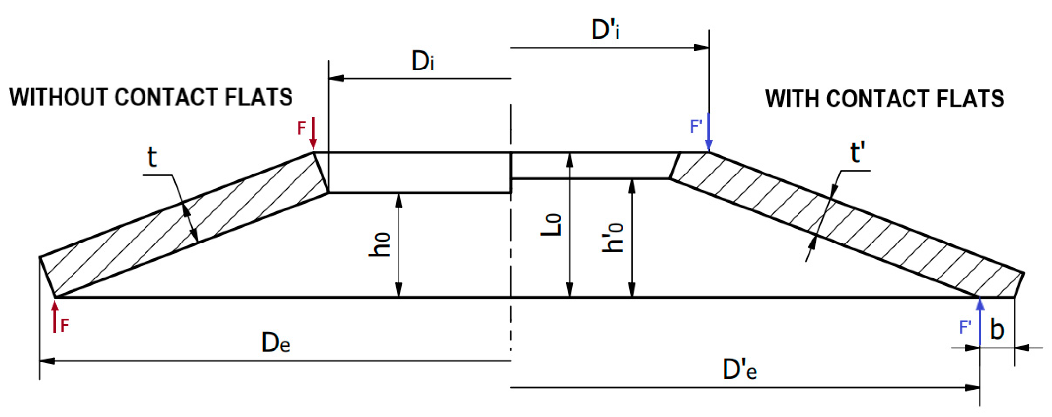
Figure 1. Characteristic dimensions of Belleville springs without contact flats (left side) and with contact flats (right side).
Machines 13 00349 g001
Figure 2. The characteristic of the relative spring force F r e l as a function of deflection s relative to the cone height h 0 for Belleville springs with different ratios of cone height to spring thickness h 0 / t .
Machines 13 00349 g002
Figure 3. Scheme as envisioned by Almen and Laszlo.
Machines 13 00349 g003
Figure 4. Comparison of the force in a Belleville spring for a deflection of s = 0.75 h 0 as a function of the ratio of the reduced thickness to the unreduced thickness t / t for the calculation methods according to DIN 2092 and Ferrari’s method.
Machines 13 00349 g004
Figure 5. The non-rectangular cross-section of the Belleville spring with rounded edges according to Leininger’s notation.
Machines 13 00349 g005
Figure 6. The force of the spring F ( β , r ) as a function of the angle β and the radius r .
Machines 13 00349 g006
Figure 7. Belleville spring stacks (a) in series, (b) in parallel, and (c) in combination.
Machines 13 00349 g007
Figure 8. Progressive characteristics of the spring stack (a) for a combination stacking (b) of springs with a series of different disc thicknesses.
Machines 13 00349 g008
Figure 9. Example discretization of the Belleville spring model for the FEA analysis.
Machines 13 00349 g009
Figure 10. The error caused by the change in mesh density. The blue line represents the relative error in the maximum stress value compared to the result obtained for the highest mesh density.
Machines 13 00349 g010
Figure 11. Comparison of F(s) characteristics for the Almen–Laszlo method and FEA, as well as the applicability range of springs depending on (a) the friction contribution for a spring D6025425 ( D e = 60   m m , D i = 25.4   m m , t = 2.5   m m , h 0 = 1.9   m m ), (b) the ratio h 0 / t for a spring with the dimensions D e = 60   m m , D i = 25.4   m m , t = 2.5   m m , and variable h 0 , (c) the ratio D e / D i for a spring D6025525 ( D e = 60   m m , t = 2.5   m m , h 0 = 1.9   m m ) and variable D i , and (d) the thickness t of the Belleville spring with the dimensions D e = 10   m m , D i = 5   m m , h 0 = 0.3   m m , and variable t .
Machines 13 00349 g011
Figure 12. Comparison of the Zheng’s method with the Almen–Laszlo method and FEA results for the D20010255 spring. (a) Spring force for D155206 series B ( D e = 15   m m , D i = 5.2   m m , h 0 / t = 0.75 ) and D155204 series C ( D e = 15   m m , D i = 5.2   m m , h 0 / t = 1.38 ), (b) force of a spring with a tripled thickness t , and (c) force of a spring with a doubled h 0 .
Machines 13 00349 g012
Figure 13. Characteristics F(s) for springs with contact flats calculated according to the DIN 2092 standard method, Ferrari’s method, and FEA: (a) standard spring t / t 0.94 and (b) spring with a non-standard ratio t / t = 2 / 3 .
Machines 13 00349 g013
Figure 14. Comparison of the characteristics of the Belleville spring D125646 according to the Almen–Laszlo method, Leininger method, and FEA (a) with curved edges r = 1.5   m m , (b) with a non-rectangular cross-section β = 30 ° , and (c) with curved edges and a non-rectangular cross-section r = 0.5   m m and β = 5 ° .
Machines 13 00349 g014
Figure 15. Comparison of the analytical method and FEM: (a) hysteresis for a single disc spring, (b) hysteresis of three springs stacking in parallel, (c) hysteresis of six springs stacking in parallel, and (d) hysteresis for ten springs stacked in series.
Machines 13 00349 g015
Figure 16. Block diagram of analytical method selection for a Belleville spring.
Machines 13 00349 g016
Figure 17. An example of a model of a Belleville spring assembly with quasi-progressive characteristics.
Machines 13 00349 g017
Figure 18. Comparison of the developed analytical method before correction with the FEM results of the quasi-progressive characteristic Belleville spring stack.
Machines 13 00349 g018
Figure 19. Comparison of FEA results’ characteristics: (a) with characteristics obtained from the analytical method with parameter correction for the D6025425 spring assembly, (b) with characteristics obtained from the analytical method using parameter corrections from the D6025425 spring for the D2814208 spring assembly, (c) with characteristics obtained from the analytical method without parameter correction for the D2814208 spring assembly.
Machines 13 00349 g019
Table 1. Equations enabling the analytical determination of parameters.
EquationDescriptionUnit
j = 0 j = m i 1 s m j s m i j = 0 j = m i 1 s m j + s m i m a x -Deflection range (corresponding to each deflection stage)[mm]
s m a x = m h 0 - Maximum calculated deflection[mm]
s m i m a x = j = m i j = m 1 n m j 1 m s m a x -Maximum deflection in a given deflection range[mm]
k i = s m a x s m i m a x -A parameter defining deflection as a fraction of the maximum deflection at various stages[-]
s m w m i = s m i m a x k m i 1 m 1 n m w -Deflection of individual segments in a given deflection range[mm]
l m w m i = s m w m i s m i m a x -A parameter defining deflection as a fraction of the maximum deflection of a given segment at various stages[-]
Table 2. Corrected parameters for the three-segment stack of Belleville springs D6025425.
The Arrangement of a Belleville Spring StackParameterDetermined from FEA Models
Machines 13 00349 i001 s m i m a x s 1 m a x = 1 2 s m a x
s 1 m a x + s 2 m a x = 4 5 s m a x
s m w m i s 1 m 1 = 3 5 s 1 m a x
s 1 m 2 = 6 25 s 1 m a x
s 1 m 3 = 4 25 s 1 m a x
s 2 m 2 = 2 3 s 2 m a x
s 23 = 1 3 s 2 m a x
s 33 = 1 5 s 2 m a x
Disclaimer/Publisher’s Note: The statements, opinions and data contained in all publications are solely those of the individual author(s) and contributor(s) and not of MDPI and/or the editor(s). MDPI and/or the editor(s) disclaim responsibility for any injury to people or property resulting from any ideas, methods, instructions or products referred to in the content.