Abstract
An additive manufacturing process should produce repeatable results as far as the properties of the material and the geometric dimensions that have to be adopted by a company as a production method are concerned. This represents a challenge for such high-volume sectors as the automotive industry, where quality and reliability are extremely important. One way of addressing this challenge is to qualify the process. A common framework has here been identified starting from the analysis of the factors that influence the stability of the result in the main phases of metal powder bed fusion (PBF) processes. A qualification procedure (QP), which offers possible solutions to help reduce risk factors, has been proposed. This procedure is independent of the industrial sectors, of which type of materials and metal PBF processes, and of the manufacturer of the used PBF system.
1. Introduction
Although additive manufacturing (AM) has existed for decades and has already revolutionized the production of polymeric material components, new AM technology developments are providing industries with the possibility of building structural components with a variety of metal alloys, ceramics, and composite materials. The major drivers of interest (Table A1 in Appendix A) that have led to the introduction of metal AM processes in such industrial sectors as the aerospace [1], automotive, defense, jewelry, medical [2], and tool making [3] fields, are the significant reduction in the lead times of the components, innovative designs with higher strength, lower weight and fewer potential failure points from joining features, and reduction of waste material [4,5].
The AM technologies that are used for metal components include different production methods than can broadly be classified into two major groups: Powder bed fusion (PBF)-based technologies and directed energy deposition (DED)-based technologies. In the PBF process, an energy source (laser (L) or electron beam (EB)) selectively fuses regions of the powder bed according to a model of the digital part. When the selective melting of one layer has been completed, the building platform is lowered by a predetermined distance (usually 20–100 μm for L-PBF and 50–200 μm for EB-PBF) and the next layer of powder is deposited on the previous one. The process is then repeated with successive layers of powder until the part is completely built. These processes are generally known as selective laser melting (SLM) and electron beam melting (EBM). Focused thermal energy is used in DED processes to fuse materials as they are deposited. Unlike DED, which is generally used to add metallic material to existing metal parts, but also for welding and repair applications, PBF processes also allow complex geometries to be constructed. For this reason, PBF-based technologies are currently having a greater impact on many industrial sectors. In the same way as for traditional manufacturing processes, the qualification of the PBF process on each AM machine is essential. To date, no qualification standards or procedures for metals AM have been fully defined or adopted. Standards organizations, like the American Society for Testing and Materials (ASTM) and the International and the American Welding Society (AWS), have created parallel but distinct standards for metal alloys produced by means of AM. In 2013, ASTM and the International Organization for Standardization (ISO) began collaborating to develop international standards (Table A2 in Appendix A). In March 2016, America Makes, the National Additive Manufacturing Innovation Institute, and the American National Standards Institute (ANSI) launched the America Makes and ANSI Additive Manufacturing Standardization Collaborative (AMSC). AMSC was established to coordinate and accelerate the development of AM standards and specifications at an industrial level consistent with the interests of the main investors to facilitate the growth of the AM industry. Although multinationals in the aerospace sector are investing enormous resources in AM metal technologies and are driving the demand towards the development of new AM metal alloys and production equipment, the lack of comprehensive and complete standards has led to fragmented information being made available to the industry. However, no methodology for the qualification of PBF processes has yet been standardized by the industry. The qualification and certification of a process in an industrial field means ensuring repeatable qualities with the same printer, materials, and operators, guaranteeing quality in any location, without any direct input from the part designer, and recognizing situations in which quality is not or cannot be guaranteed [6]. Therefore, the quality of AM manufactured parts and their designed functionality can easily be impaired, considering the variety of parameters that can influence the AM process. L-PBF and EBM are complex and meticulous processes, which require certain experience and skills to satisfy the quality expectations of industrial applications. The choice of the process parameters to produce the part from metallic powders is of fundamental importance, as the thermal history of an alloy affects its integrity and strength. The quality assurance (QA) level and process stability require detailed knowledge of the process as well as further improvements so that this technology becomes suitable for large-scale serial production. The QA of AM is not a single step, but involves a set of analyses, measurements, and inspections performed throughout the entire process of the part production, together with the relevant documentation. The results obtained from this workflow can lead to a qualified part, and the data that are collected and interpreted can be summed up in a qualification procedure (QP). The contribution of this study is to identify the critical points of the PBF processes through the analysis of the various phases to create a QP. A QP for the AM process requires a methodology to evaluate all the variables and factors that can affect the technical requirements of the final part as well as the reliability and reproducibility of the process. Portolés et al. [7] proposed a QP for the production and repair of aerospace components produced by means of EBM. This methodology considers, through nine steps, all the parameters that could influence the technical requirements of the finished parts and the reproducibility of the process. These phases span from the validation of the recycled powder to the finishing of the built parts. The procedure defines the key variables that have to be tested at each step, sets reference values for the variables according to international standards requirements, wherever applicable, and proposes experimental procedures to perform the corresponding verification tests. However, it is worth noting that some of these steps only pertain to aerospace part repairs. Bassoli et al. [8] proposed an exploratory standardization of the procedure that has to be followed to develop a complete set of process parameters for the L-PBF of innovative alloys, new machines, or untested alloy/machine combinations. However, this procedure does not consider the possible numerical combinations of the process parameters that generate the same density energy values albeit with different results [9]. Moreover, the effect of the choice of the geometric parameters of the block support is not considered for the support structures [10]. Yeong and Chua [11] proposed a quality management framework to implement AM for medical devices. This framework investigates such topics as software and data inputs, AM equipment, and the understanding of processes and products. In 2012, DARPA (Defense Advanced Research Projects Agency) established a project, called open manufacturing program, to develop an integrated computational materials engineering (ICME) framework aimed at a rapid qualification of process. Such a rapid qualification requires the integration of several aspects of the AM process, that is of the materials, design, models, process, monitoring and control, non-destructive evaluation (NDE), and testing. Moreover, in-situ process monitoring should be implemented, especially in the aerospace sector, for certification purposes, to provide evidence in the form of in-process quality assurance (IPQA®). A probabilistic design approach was adopted by Peralta et al. [12] in a rapid qualification process to enable the integration of these aspects in a single risk-based function in order to optimize the design process. Simulation tools are used in the rapid qualification model to simultaneously analyze the product development phase, which is therefore not sequential but concurrent: The manufacturing, materials, and design are at the same level. Moreover, in-process monitoring is also used to validate the models together with IPQA®. Experimental tests, process monitoring, and non-destructive evaluations have been conducted to fully quantify the uncertainty of the proposal framework. The results are encouraging, but there is still a need to improve the computational efficiency of the process in order to enable the simulation of the larger build spaces that are associated with real-world components.
A QP requires the evaluation and control of raw materials, consumables, and process parameters, as well as the development of a fixed sequence of clear operations that should be followed for each AM component. A QP should consider the potential dependencies between the different process variables in a specification procedure. Therefore, a QP should be defined for each combination of technology and materials. Should one of these elements of the process be changed, it will be necessary to prepare a new qualification plan that is congruent with the new scenario. However, it is possible to identify a common framework that starts from the analysis of the factors pertaining to the main steps of the AM process that influence the stability and therefore the results of the process. The QP proposed in this study has the aims of identifying such a common framework and solutions that can help reduce the risk factors regardless of the industry sectors, the type of materials, PBF process (L-PBF or EBM), and of the manufacturer of the used PBF system.
2. Methodological Approach
The first objective of a QP is to determine the fundamental steps of a generic AM process, which include three main phases: Digital, manufacturing, and post-processing (Figure 1). Each of these phases contains several sub-phases, some of which, especially in the post-processing phase, depend on which AM technology is used.

Figure 1.
Main steps of the additive manufacturing (AM) process.
The 3D model creation sub-phase (a 3D model of the object is first created using computer-aided design (CAD) software or a 3D object scanner) and the data preparation sub-phase are part of the digital phase. In the latter sub-phase, a CAD model is converted into an STL (stereolithography, which also known as standard tessellation language) file to tessellate the 3D shape and the STL file is then processed by means of slicer software, which generates a job-file that is subsequently saved in custom built machine format. The manufacturing phase includes the machine setup (the material is loaded, and the printer is set up with process parameters) and the building (the printer builds the model by depositing material layer by layer). The following sub-phases are generally identified in the post-processing phase: Part removal (the part is removed from the build platform), support structures removal, heat treatment, shot-peening, and finishing.
Once the key points of the process have been determined, the overall vision is completed, and a model is prepared for the process qualification. For an additive process to be competitive, it is necessary, in the same way as in traditional technologies, that the design of a component is carried out based on the technology and material chosen for the production and that the technology is not adapted to a component designed a priori. Once the technology and the material have been chosen, it is important to know the limits of the process in order to design the components in the best possible way. To this end, the principle constrains/problems of the main phases were highlighted. Then, possible solutions to reduce problems due to controllable factors, were indicated in the QP.
3. Results and Discussion
The quality of the produced components is determined, to a great extent, by the quality of the used dataset, the orientation of the components during printing, humidity, temperature, material selection, powder state, gas flow/surrounding atmosphere, powder properties, layer thickness, process parameters, and post-processing (Figure 2).
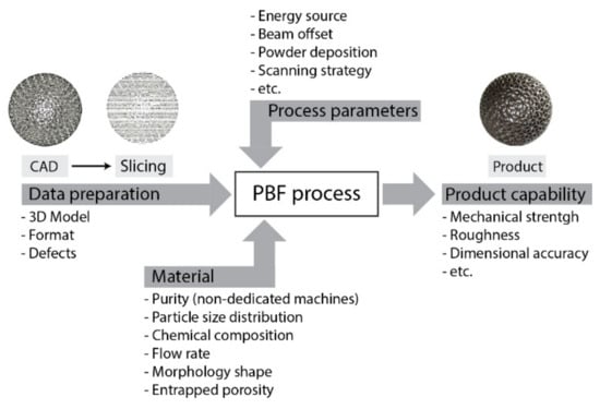
Figure 2.
Some parameters on which the quality of the component depends.
3.1. Digital Phase
Klahn et al. [13] highlighted two design strategies that can be used to take advantage of AMs in product development: The manufacturing-driven design strategy and the function-driven design strategy. In the first strategy, the designer maintains a conventional design and complies with the design rules of other manufacturing technologies. AM dental implants are an example of this strategy: The shape of implants is not modified when changing from conventional casting or milling processes to AM. The flexibility of the AM permits one to produce an individual implant for each patient at lower costs [13]. The latter design strategy instead exploits the AM features to improve the features of a product. The full potential of additive manufacturing freedom is exploited in the design phase. Therefore, this type of strategy excludes the possibility of transferring a component to conventional production, without first making major design adjustments. It is precisely in this context that the design for additive manufacturing (DfAM) was developed. Chu et al. [14] defined the aim of DfAM as “The synthesis of shapes, sizes, geometric mesostructures, and material compositions and microstructures to best utilize manufacturing process capabilities to achieve the desired performance and other life-cycle objectives”. In the initial phase of DfAM, the designer is still free to modify the geometry and make design choices (“Concept Phase”). Little by little, going forward with the design, this freedom is constantly reduced (“Detail Phase”), while the level of knowledge of the technology increases constantly (Figure 3).
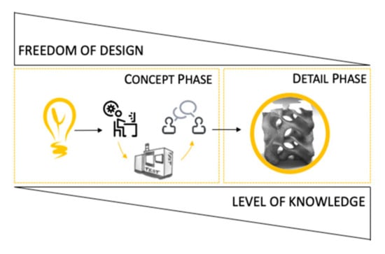
Figure 3.
A quick sketch representing the workflow for successful and quick part design.
In DfAM, it is important to clarify the relevant requirements, that is, to identify and prioritize the requirements for the selected application and define the production process chain in order to identify any potential problems that may require alterations of the final geometry later on. The designer should, for example, consider the orientation that best fits the characteristics of the specific product during the ideation stages, as it will most likely involve trade-offs between different features [15]. In the L-PBF and EBM processes, the part orientation, position, and arrangement on the building platform can have a great impact on the process speed, process stability, and various component properties, such as residual stress-induced warping (“curl effect”). In addition to fixing a part onto the building platform (in L-PBF) and the use of supporting overhanging structures, support structures may also be necessary for heat dissipation, the avoidance of residual stresses, and the compensation of residual stress-induced warping [10,16,17]. This is particularly important in L-PBF: On the one hand, the melt pool has a much higher density and weight than the non-melted powder and sinks into it, while on the other hand, the unmelted powder shows much less thermal conductivity than a solid material and therefore does not provide enough heat transfer [18]. Subsidence is avoided and heat transfer is improved by using support structures. However, residual stresses, caused by an uneven heat distribution, cannot be avoided completely and, in many cases, a post heat treatment (anti-stress annealing) is recommended. The part should still be attached to the construction platform during heat treatment to minimize deformations. These structures can also be designed to be part of the component itself. In the EBM process, due to the vacuum environment and the heating steps, the total temperature gradients are much lower than in the laser process, and the built components therefore also exhibit substantially lower residual stresses and relative deformations. Thanks to this preheating, there is no need to support the structure against subsidence in EBM, but there is still the need to improve heat dissipation in order to avoid overheating effects. Therefore, support structures can be designed much thinner, i.e., with less volume, than in L-PBF, and there is no need to attach them to the start plate. As a result of the combination with the process-specific preheating of each layer, the resulting residual stresses are much lower and usually do not require subsequent stress-relief annealing. Such critical hotspots and the related distortion can be minimized by appropriately orientating and positioning the components, which prevents large-area fusion within a single layer.
As far as the modeling of a component for additive processes is concerned, with the advent of AM technologies, topology optimization tools have been used by designers as a valid aid in the redesigning of parts where there is a need to reduce the weight of the component. Topology optimization tools generate a complex natural shape that is the result of the removal of materials according to the goals and constraints set in the design phase. The project is then finalized, by means of CAD software, on the basis of the form generated in the topology optimization process. The final optimized design is validated using finite element tools whether the design requirements have been met to ensure its overall performance. However, care should be taken when models are generated with topological optimization tools, since the indications given often need to be reviewed as they can generate zones that cannot be produced by means of PBF processes. In addition to checking the simulation and modeling software, attention should also be paid to the conversion of the 3D CAD file into the file used by the AM software. STL has been the file format for AM since the mid-1980s when it was developed by 3D Systems. In 2011, ASTM introduced the additive manufacturing file (AMF) format as an alternative to the STL file format. STL files introduce errors such as leaks and inconsistencies since the complex mathematical description of the geometry of the solid surface is simplified into a series of logical small triangles known as facets. The size and number of facets determine the accuracy of the surfaces. A mesh with large triangles creates a small STL file and produces a prototype with visible facets. A mesh with triangles of the same size as the material thickness produces an accurate prototype. A smaller triangular mesh increases the size of the STL file and requires longer digital processing times (subsequent repairs, slicing, etc.) and does not have the same accuracy as the added prototype [19]. Furthermore, the large size of some files (greater than 1 Gb) can cause the software of some machines to crash. The aim of AMF is to address these issues by redesigning the way a 3D object is digitally stored. The AMF format is based on a volume-based method. Although the volume mesh reduces the amount of data, compared to the STL file, it is more complex, and most AM machines are not compatible with AMF files. Thus, this limits the usage of AMF. Table 1 summarizes the main defects and their links with the data preparation for L-PBF and EBM.

Table 1.
Main defects that can appear due to the data preparation (○ laser (L)-powder bed fusion (PBF); ● electron beam melting (EBM)).
3.2. Manufacturing Phase
3.2.1. Raw Material Quality
The number of research projects on PBF process powders has grown rapidly in recent years due to a mature awareness of the industry of the importance of obtaining a complete understanding of the properties of powders. Like other powder metallurgy processes, the chosen powder plays an important role in obtaining competitive mechanical properties [18]. Important factors, such as the powder characteristics, material contamination, and powder reuse, can influence the quality of the final part. One of the most important benefits of the PBF process is the possibility of reusing any non-consumed powder material, which results in a more cost-effective and sustainable process. In the PBF processes, the powder in the build chamber that is not used to build a component is collected in a container. The unused powder particles, especially in the L-PBF, can form agglomerations [20,21,22,23,24]. A fine powder agglomerate is more likely to favor the formation of pores and voids during processing, due to the irregular shapes and variable dimensions of the formed agglomerates [25]. Furthermore, agglomerated powders are known to increase the reflectivity of the powder bed, with a consequent lower energy absorption during the production process, which in turn has an impact on the flow behavior [26]. Tang et al. (2015) characterized Ti6Al4V powder after it had been used 21 times in EBM. The impact of reuse on powder flowability and on the mechanical properties resulted to be positive. Another study carried out on Ti6Al4V in an L-PBF system has shown an increase in oxygen, from 0.09 wt.% to 0.13 wt.%, and spherical powder particles after 31 builds. This led to a slight increase in the tensile strength, which can be explained by considering the strengthening effect of oxides [27]. Metal powders used for PBF are normally characterized by means of the same tools and techniques as those adopted for traditional powder metallurgy processes [20]. Most of them link the morphological and chemical changes with flowability behavior. However, each PBF technology has unique attributes; for example, the powder-spreading mechanism differs for different brands of L-PBF machines (blade, rubber). These differences should be considered when developing new characterization techniques. In general, it is assumed that the powders are nominally spherical in PBF processes, with a particle size distribution that facilitates the packing and minimizes the porosity of the final parts. The humidity of powder has the effect of making the particles stick together and leads to poor flowability measurement results [28]. Therefore, it is strongly recommended to store the powder in places with controlled temperature and humidity and to dry the powder regularly.
Another important aspect that should be considered and that can influence the mechanical properties of the final component is powder contamination. It is important that the PBF powders should not be contaminated by foreign particles derived, for example, from other batches of material used in the same production plant, or in the PBF machine, or from debris present in the processing and recycling equipment. Furthermore, according to ASTM F3303 (Table A2 in Appendix A), the powder must be packed in containers capable of preventing moisture from penetrating the containers. Desiccant bags, labels, or tags shall be placed inside the containers in contact with the powder. Powder shall be stored in environmental containment to prevent contamination and moisture absorption. The room temperature should be limited to 20 °C to 25 °C at 60% relative humidity, and 25 °C to 30 °C at 45% relative humidity. Room conditioning is necessary to maintain constant temperature and humidity values.
3.2.2. Process Parameters
Knowledge of the process parameters that have to be used for a given material is extremely important in order to comply with the specifications of the designed model. There are many studies in the literature on L-PBF that have focused on the correlations between the input parameters of the process and the quality of the product [29,30], on the definition of the relationships between the process parameters and the characteristics of the melt pool [29,31,32], as well as on the control strategies of the process [33,34,35,36,37]. There are over 50 different process parameters in L-PBF that influence the final quality of the manufactured component, and as a result, there may be a certain level of difficulty in understanding the physics of the process and in developing an effective control strategy [19,38,39,40]. Each of these parameters can be changed independently, but the selection of the parameters generates a multi-variable problem. The main critical parameters considered in the literature are [9,40]:
- Laser power (the total energy emitted by laser per unit time);
- Spot size (diameter of the focused laser beam);
- Scan speed (the velocity at which the spot is moved across the powder bed along a scan vector);
- Hatching distance (the spacing between neighboring scan vectors);
- Scanning strategy;
- Layer thickness (the depth of each new powder layer to be melted);
- Powder material properties (shape, size, and distribution);
- Beam offset (the diameter of the melted zone is usually larger than the laser diameter and is called spot diameter. In order to compensate the dimensional error due to spot diameter, the laser beam should be offset from the boundaries of the cross-section of the object and is called beam offset).
These parameters have a complex effect on the transient thermal behavior of the melt pool, and often result in unexpected defects such as pores [41], high surface roughness [38,42], thermal cracking and delamination [43], unintended anisotropic mechanical and physical properties [44], as well as anisotropic shrinkage [45].
The way in which the laser beam interacts with the powder material during the process and the dynamics of the melt pool are largely a function of the powder material and the thermodynamic properties [40]. In addition to the thermophysical properties, the powder particle shape and size distributions can also be important as these affect the absorption of light [46,47], the flowability of the powder during the recoating process, the packing of the powder bed, and the uniformity of layers deposited in the recoating process. If the powder is reused, these properties are susceptible to changes due to sieving, contamination, or vaporization of some elements that make up the metal alloy and the subsequent condensation of the material arising from the melting of any waste material (support structures, components with defects). The shape and stability of the melt pool may change during the process. As the melt pool grows, solid powder grains (satellites) become connected to the edges of the melt pool [48]. Conversely, if the energy supplied to the melt pool is too small or the laser fusion time is too short, a “balling effect” becomes evident. However, there is a range of speed values for each material, beyond which the behavior of the melt pool becomes unstable and a beading effect, which is known as “balling up”, is created. Furthermore, as the laser power increases, the formation of spatter increases, which can interfere with the surrounding area (powder bed and adjacent molten parts). If the scan speed is too high and the laser power too low, there will be regions in the part that do not melt completely, which lead to a “lack of fusion” and porosity. Conversely, if a high power is applied for the chosen speed, the melting pool could be overheated, and this can cause a deeper energy penetration, which induces what is known as the "keyhole formation" effect. A power–speed–energy density diagram (Figure 4) is generally used to identify these areas. Energy density is the energy input of the laser beam per unit volume [31]. Unfortunately, this approach, which is aimed at characterizing the overall complexity of L-PBF processes by means of a single number, has been shown to be insufficient [9,32,49].
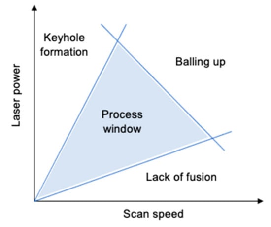
Figure 4.
Laser power vs. scan speed graph: Process outcomes with parameter choices.
The EBM process involves complex physical mechanisms, and their understanding and description still represent a challenging task. The most significant mechanisms can be summed up as the spread of particles, the sintering of particles, the melting of particles, and the evaporation of some alloying elements [37]. The spread of powder particles, or of the so-called smoke, occurs as an explosion when the EB hits the powder bed. Such a phenomenon causes the powder to spread throughout the chamber and outside the melting area, thereby causing a non-uniform layer, a lack of material that has to be melted, and even the shutdown of the EB. The smoke phenomenon is material-dependent, and an appropriate sintering level of particles plays a key role in this process. Because of that, unlike the L-PBF processes, the operative phase consists of different steps. After the powder distribution, two subsequent steps are conducted to preheat the powder bed. In the first step, the powder bed is uniformly preheated by a series of beam passages [50]. The powder is then subjected to a further heating step in a restricted area corresponding to a predefined offset of the actual melting zone. While the former preheating is mainly aimed at avoiding the spread of the powder during the melting phase [37], the latter decreases the thermal gradient for the subsequent melting phase. The typical preheating temperatures are close to the melting point of the processed material, e.g., 700–800 °C for Ti6Al4V and up to 1050 °C for Ti48Al2C2Nb. The last step is a balancing phase, which is also known as post-heating [51]. The process parameters are material and machine dependent. For instance, Arcam company provides a set of process parameters for its powders, called themes, which are optimized and tailored to a specific machine model and material. The main critical parameters for the quality part can be summarized as:
- Intensity of the beam current;
- Focus offset, which is the additional current that translates the focal plane from its zero position and adjusts the beam diameter [52]. The beam current and the focus offset together to control the spot size [37];
- Speed function is a function that assigns a certain speed of the beam accordingly to the beam current. Negative speed function values mean a linear correlation between the current and the speed of the beam;
- Scanning strategy for the preheating steps. The parameters here are set to achieve a desirable temperature and sintering level before to melt the material. The number of beam passages and line order are an example of the additional process parameters that need to be defined;
- Scanning strategy for the contour and the inner area. Number of beam spots, the spot time, and the minimum distance between two consecutive jumping points are the additional process parameters to be defined in the MultiBeamTM strategy. During MultiBeamTM, the control system rapidly moves the beam according to a discontinuous pattern. Separate melt pools are activated at different points of the contour that are molten quasi-simultaneously [37];
- Line offset (similarly to the hatching distance for the L-PBF);
- Layer thickness;
- Layer rotation.
In addition to the above-mentioned process parameters, other derived quantities have been considered significant in the literature for the quality of a part; that is, the energy density [53] and the line energy [54]. Energy density is the ratio between the power and the section of the beam, while line energy is the ratio of the power to the scan speed. Beam power is the product of the acceleration voltage (60 kV) and the beam current. Since the EBM process is a hot process, heat transfer plays a key role in the success of the process. Care should therefore take with each process parameter in order to consider the actual temperature distribution. The heating phases, that is, both preheating and post-heating, sinter the powder particles and improve the heat transmission between the melted line and the surrounding area during the melting phase [55]. A proper sintering level improves the powder strength [56], and the number of surfaces that need to be supported during the building may therefore be reduced. The preheating phase and the vacuum environment ensure high temperatures and low thermal gradients during the process. Therefore, the sintering level grows as the smoke phenomenon has been avoided. Conversely, for the case of a poor sintering, adhesion of the smaller particles is favored and surface roughness becomes worse [57]. Surface roughness is closely correlated with the size of the powder particles, their distribution [57,58,59], and the orientation of the part. Sintered and unmelted powders could also be responsible for crack initiation [60,61,62]. High values of the focus offset, scan speed, and line offset decrease the surface roughness [59] but increase the risk of balling effect [53,63,64,65,66]. The droplets formed as a result of the balling effect could produce unmelted regions that make powder raking unreliable [67]. Unmelted regions and porosity of the layer could be reduced by increasing the line energy and/ or the energy density. As high line energy is required, high beam current and/or low scan speed values need to be set [68]. However, because of the relationship between the beam current and the beam spot, the energy density value could decrease and the opposite effect could be obtained [37]. An unmelted pocket can be formed for a certain line offset value [69]. However, it may be difficult to find a good compromise, because the variation of just a single process parameter can affect several aspects of the process.
Table 2 summarizes the main defects and their link with the raw material, process parameters, and machine for L-PBF and EBM.
Table 2.
Main defects that could be appeared on a part produced by L-PBF (○) and EBM (●) processes.
From this, it can be deduced that it is essential to understand the correlations between the physical and chemical properties of the powder, the processing performance, and the properties of the final components. The powder properties can be grouped into three levels [18]: The lowest level, called “powder properties”, describes the physical or chemical properties of the particles; the second level, named “bulk powder behavior”, describes the behavior of the powder ensemble as a whole; the third level, called “in-process performance”, describes the behavior of the powder under specific process conditions. Figure 5 shows, for each level, the aspects that influence the distinct key characteristics that describe the quality of the final part in terms of accuracy, density, surface roughness, mechanical properties, and internal build flaws.
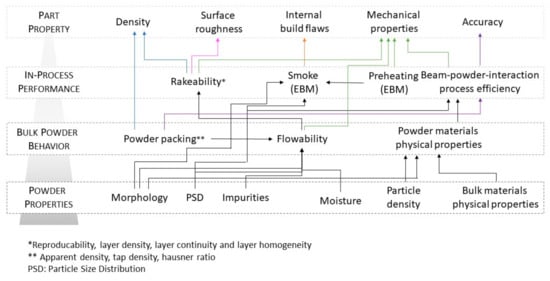
Figure 5.
Relationship between powder properties, bulk powder behavior, powder performance in the process, and the quality of the parts.
3.2.3. Operator
Other factors that should be checked, in addition to those highlighted in the literature, which are mainly related to the process parameters and material, and which can influence the success or failure of the manufacturing phase, are the state of maintenance, the setting, and the cleaning of the machine. Human errors are arguably the greatest cause of risks to ensuring that an AM part meets all the required standards. This is because PBF requires human intervention, for example, to design and remove the supports and to post-process and check that all the requirements have been met at each stage. This level of human intervention inevitably increases the risk of the final part being compromised.
3.3. Process Monitoring
Although metal PBF systems are advancing continuously, the incorporation of these technologies into industrial production cycles requires high-quality standards. Comprehensive process monitoring needs to grow to ensure an integrated and traceable production. In recent years, some L-PBF machine manufacturers have made various modules available to monitor, document, and verify L-PBF builds, which is especially important for industries with high-quality requirements. Some of these modules can be used to monitor the melt pool and the laser power. The monitoring of the melt pool is realized by measuring the thermal radiation from the melt zone. This system takes a sequential image of the thermal emission plot of an individual layer. The acquired measurements and the parameters are not dependent on the material, and they can help and support the development and optimization of process parameters. The monitoring of the laser power allows the target and the actual emitted laser output to be documented during the entire production process, with the advantages of a QA of the build jobs and a cost reduction as a result of error-free parts. In the last few years, commercial systems that provide process control and the QA of printed parts have become available for the real-time in-situ monitoring of AM processes. Concept Laser has developed an in-situ QA system, QMmeltpool 3D, which utilizes coaxial sensors to identify the melt pool area and the melt pool intensity. The system documents the position-related characteristics of the melt pool when the part is being printed, thereby providing local indications of any defects in the part. EOS GmbH has introduced EOSTATE MeltPool, which, during the build process, after separating the process light from the reflected laser light, measures the light emission of the melt pool and captures and processes the captured data. The captured data can be used to draw conclusions on the quality of the printed parts. Process monitoring is carried out at each spot, each layer, and each part during the build process, thereby lowering QA costs. Arcam AB has recently implemented two systems for process quality control and monitoring. The first system is called LayerQam, and it has a high-resolution camera for defect detection. After the post-heating step, the camera acquires a picture of each layer. This picture is compared with the ideally computer-aided design (CAD) section and a porosity report of the entire build is delivered at the end of the process. Therefore, this camera can highlight the presence and a lack of fusion defects. The second system is named Arcam XQam and it is an X-ray detector that works like an SEM microscope. To date, this system has been used to automatically calibrate the EB to eliminate the necessity of any operator intervention and to ensure a high repeatability and quality of the EB. Both systems are currently implemented in a closed-loop control system. A closed-loop control system allows AM machines to achieve the quality target and prevents the failure of the process and scrap parts by directly modifying the process parameters in real time and adapting the process to the various factors that contribute toward the success or failure of the production of a component. An example of a closed-loop control system for EBM technology is that of the rake system controls. This system is equipped with sensors that check the amount of distributed powder on the previous layer. If the amount of powder is out regarding the target, a regulation system adjusts the amount of the powder fed to the layer and, if necessary, the rake again distributes a certain amount of powder to avoid a non-uniform layer thickness that could lead to a lack of fusion and to a smoke phenomenon.
3.4. Post-Processing
The post-processing phase concerns all the operations necessary to obtain the finished product, such as support removal, the detachment of a component from the building platform, the heat treatments, the cleaning and finishing of the part, as well as the inspection phase and mechanical tests.
After the build has been completed and the parts/building platform has cooled down, the machine operator removes all the powder from the build volume and sieves/filters/recycles it for later use. This is not an expensive step, but it takes time. In L-PBF, the heating and cooling of the metal, as the part builds layer-by-layer, leads to internal stresses that should be released before the part is removed from the building platform, otherwise the part may warp or even crack. The stress-relieving phase requires an oven or a furnace, preferably with environmental controls, that is large enough for the entire build plate and components to fit into. Possible setup errors of heat treatment furnaces or any loose powder remaining in the component, e.g., inside the channels, for some materials, before the heat treatment, can lead to having to discard the component.
L-PBF parts are generally detached from the building platform by means of a wire electrodischarge machining (EDM) [70] operation that removes the parts, and the support structures are then removed manually. This sequence of steps can lead to subsequent deformations of the component and/or damage if the component is not fixed properly in a vice for removing the supports. The correct procedure is to first manually remove the supports and then remove the component from the platform. In the case of EBM, the supports are not attached to the start plate, and there is therefore no need to use a cutting machine. In general, the supports can simply be removed manually as they are easy to break. However, because of the preheating phase, the powder around the component is slightly agglomerated and the part needs to be cleaned by sandblasting using a powder recovery system (PRS) in which the same processed powder is used. Instead of a heat treatment, many aerospace companies are starting to use hot isostatic pressing (HIP), which is already frequently used in the casting industry to improve the fatigue life of cast parts. The machining of mating interfaces, surfaces, threads, support structures, and more will likely be required to ensure dimensional accuracy of the finished part. Only a few AM parts meet the “as built” specifications, and if nothing else, the surface of the part that was connected to the building platform will need to be finished. Most manufacturing companies already have machining systems on hand, but registering parts and establishing datums for machining can be tricky, especially for complex, organically shaped parts made by means of AM. Surface finishing might also be required to improve the surface finish/quality, reduce surface roughness, clean internal channels and/or remove partially melted particles on a part. To date, there are no systems, especially for aluminum alloys, that are suitable for surface finishing, especially for internal channels, and which do not affect the accuracy of the part.
Metrology, inspection, and non-destructive tests using light blue scanning, dye-penetrating testing, ultrasonic testing, and computed tomography (CT) are used before and after post-processing. Destructive tests are also carried out on parts of samples to analyze the witness coupons (for example, tensile bars), the chemistry of the powder, and the microstructure of the materials. The data are collected as they are useful for the qualification of the processes and, eventually, for a partial certification. Most companies have a series of metrological and non-destructive testing methods, but PBF parts with internal channels, reticular structures, and other internal improvements may require CT scanning to ensure the complete removal of loose powder from the part and to evaluate the internal geometries. Besides final inspection of products, NDT can be used during manufacturing in terms of monitoring and even control of process quality. In recent years, much research has been going in this direction. The online analysis outlined assumes that non-destructive evaluation (NDE) measurements can be conducted during the manufacturing process and process measurement data on-the-fly, reducing the bottleneck apparent in the layer completion time [71].
3.5. Qualification Procedure
Figure 6 depicts a flowchart of the necessary steps that have been discussed above for the realization of components that can be qualified by an industry that use PBF processes. Understanding the nature of the raw material used for metal AM is fundamental to qualify the overall manufacturing process as well as to generate uniform products. The raw material for PBF processes should pass through two characterization phases. The first involves the certification of the powder quality by the raw material suppliers. In the second phase, tests should be carried out on the raw material before storing it to ensure that the actual material matches the quality performance of the previous batches or lots. Powder characterization and testing are required to evaluate the chemical and physical properties of metal powders, both as individual particles and in loose form. A document containing the certificate of analysis (CoA) from supplier, inspection, and testing of materials by QA group should be drawn up (raw material (RM) document).
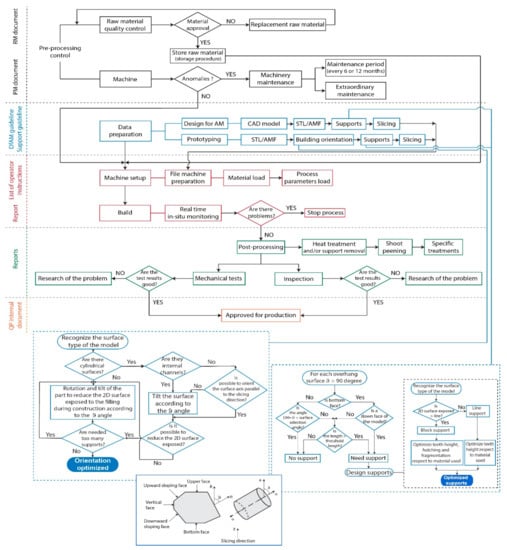
Figure 6.
Qualification procedure for metal PBF process.
Once the quality of the powder has been ascertained, it can be stored according to the storage procedures. Storage units for metal powders are designed according to regulatory standards and have safety attributes that meet the requirements for the specific metal powder being stored as fire-rated wall construction, automated fire detection, and dry powder application. Electrical standards and earthing requirements are also critical to prevent the build-up of static electricity and other ignition sources. The standard storage procedure is described below:
- Storage should preferably be in rooms with a fire-resistant or non-combustible construction;
- The room temperature should be limited to 20 °C to 25 °C at 60% relative humidity, and 25 °C to 30 °C at 45% relative humidity;
- Powder is stored in original container;
- Powder that is not in use is stored in standard flame cabinets;
- Separate flame cabinet used for “flammable” and “nonflammable” metals;
- Only the quantity of powder required for monthly operations is stored and no large supply is maintained, both for powder quality and safety reasons;
- Spills are immediately cleaned with powder vacuum;
- All floors in powder handling rooms are mopped at least weekly;
- All flat surfaces (tables, equipment, shelves) are inspected and wiped periodically to ensure no large buildup of powder.
In the pre-processing control phase, besides the control of the raw material, there is also the control of the machine. A maintenance document should be drawn up to schedule the preventive maintenance (PM) measures. The document should contain a list of the consumables and/or repairable materials marked with appropriate maintenance intervals. The PM should be in the form of a checklist and it should indicate the date when the maintenance has been completed. Before loading the powder into the machine for part production, all the machine components that can directly affect the successful outcome of the construction should be inspected to detect any damage or functionality problem.
The qualification activities are completed by drawing up specific designs of the AM parts and test coupons that can be used in a variety of mechanical and physical tests. For the qualification criterion, a standard guideline for geometric capability assessment of AM systems has been created by standard organizations (Table A2 in Appendix A). The part’s orientation can be adjusted to improve the quality of the overhanging features especially when the component has not been designed following the procedures of the DfAM but it is an existing part (called prototyping in Figure 6) to be built with additive technologies. The overall shape and size of the part may limit the possible orientations, since it must fit the building envelope of the machine. Because of the layer-by-layer building strategy, the quality of each surface depends to a great extent on its orientation with respect to the building platform. The orientation of the part in the L-PBF process also affects, to a great extent, the amount of powder required and the building time. When the recoating blade deposits a new layer of powder on the previous one, it slides on the melted area of the previous layer. If it encounters a large area, the force applied by the blade increases and could result in a detached of the part from the building platform or in a stall of the motor driving the recoating blade. To reduce the contact length, the part should be rotated by a small angle (from 5 to 15 degree on the building platform respect to recoating blade). The purpose of adjusting the part’s orientation is also to alter the inclined angles of overhanging surface so as to minimize the amount of support structures as much as possible. As shown in the flowchart in Figure 6, it is necessary to classify and identify the type of surface that requires support structures. Based on the evaluation of several parameters (overhang, surface area, slenderness, contour length, etc.), it is possible determine the surfaces that require support structures and types of support [10]. As more experience around the construction of support structures is gained, operators should begin to map their experience in a decision trees or in a set of general rules (DfAM and support guidelines) and best practices to help maintain knowledge of the process. It should also be taken into account that the choice of the parameters of the STL file can affect the accuracy and surface roughness of the parts.
The build phase is a critical point of the PBF build process and operators should develop a schedule to monitor the early build that would allow them to intervene or cancel the build before a substantial amount of process time has passed. Before another AM build can be initiated, the operators should assess the actual state of the PBF equipment and its build chamber. A cleaning procedure should be implemented to return the PBF equipment to its previous state for each run to ensure repeatability. After separation from the building platform, the PBF build may require additional thermal and mechanical post-processing work. The procedures for these operations should be associated with the PBF process and material for later analysis and traceability. Many different factors can influence the quality of AM builds, some of which need to be keep under strict control:
- The characteristics of the powder, together with the process parameters and the scanning strategy, have influence on the accuracy, porosity, and mechanical properties, on the dimensional limits, and on the surface roughness;
- The minimal layer thickness, which depends on the particle size distribution of the used powder, has an impact on minimum feature size, accuracy along the z-axis, and surface finish. Unfortunately, although adaptive slicing may be effective when building a single part, it becomes complex to manage when there are more parts on the building platform with different geometry and, therefore, with different adaptive slicing;
- In the xy-plane, the minimum size of structural features is constrained by the size of the melt pool, which is determined by the laser-beam spot size and the process parameters (laser power, scan speed, hatching distance, beam offset, etc.). Accuracy in the xy-plane is determined for L-PBF by static and dynamic positioning errors of the scanning mirrors and by shrinkage and residual stresses associated with the transition from powder into dense metal. For this reason, geometrical constraints and possibilities are related to the material used, to the process strategies adopted, and to the PBF machine used.
In order to guarantee repeatability, calibration procedures are necessary to ensure that the basic performance of the equipment remains the same over time. The process engineers responsible for the qualification project should base the calibration procedures and schedules on the manufacturer’s documentation and recommendations. The main validator of process qualification involves the testing of different mechanical properties of the components produced with the PBF equipment under a fixed set of process conditions, including the operator. The tests should be used to select the best possible parameter settings for continued production and to understand the effect of various process choices on the performance of manufactured components. Several options are available to improve or modify the material performance characteristics after AM builds are complete. Some post-process treatments such as hot isostatic pressing and solution annealing have been shown to reduce porosity, affect mechanical properties, and modify the microstructure to the desired condition. On the thermal post-processing of parts produced by metal PBF process, an international standard issued under the fixed designation F3301 (Standard for Additive Manufacturing—Post Processing Methods—Standard Specification for Thermal Post-Processing Metal Parts Made Via Powder Bed Fusion) has been drafted to achieve the required material properties and microstructure to meet engineering requirements.
On the basis of the positive results that have been obtained for the design and production of the component, internal regulations can be drawn up for the company, which can then be integrated with the specific internal company procedures for the production of components.
4. Conclusions
L-PBF and EBM technologies are currently used as manufacturing processes for metal parts in various industries. Several studies in the literature have demonstrated the potential of these technologies but also their problems. This document represents the first steps towards a coherent set of QA considerations to meet most of the requirements required by the industrial sectors. The presented QP was developed considering the particular features of the two technologies. The methodology has been developed by fusing together the current state of the art in literature and the author’s experience with research laboratories, AM system manufacturers, and companies that already use PBF as a manufacturing process. The QP proposed here gives general indications about the crucial points of the processes that can influence the results and the possible precautions that should be taken reduce/eliminate the risk factors. However, it is evident that, given the continuous growth of materials and machines, the creation of standard procedures for these AM processes is still necessary at a higher level.
Author Contributions
For research articles with several authors, a short paragraph specifying their individual contributions must be provided. The following statements should be used “conceptualization, F.C.; methodology, F.C.; investigation, F.C. and M.G.; writing—original draft, F.C and M.G; writing-review, F.C., M.G and L.I.
Conflicts of Interest
The authors declare no conflict of interest.
Appendix A
Table A1.
The major drivers of interest that led to the introduction of metal AM processes in industrial sectors.
Table A1.
The major drivers of interest that led to the introduction of metal AM processes in industrial sectors.
| Applications | Value Drivers | ||
|---|---|---|---|
| Performance | Time | Production Cost | |
| Prototyping (for product development) | ✓ | ✓ | |
| Spare parts (for service) | ✓ | ✓ | |
| Rapidly print manufacturing aids | ✓ | ||
| Assembly (reduce assembly costs and improve performance) | ✓ | ✓ | |
| Lightweighting (remove mass with geometry not possible conventionally) | ✓ | ||
| Conformally cooled tooling (improve molding/casting cycle time and part quality) | ✓ | ✓ | ✓ |
| CNC machine parts (printing near-net-shape to reduce scrap and machine time) | ✓ | ✓ | |
| Low volume previously cast/forged part (eliminate tooling to reduce lead time and cost) | ✓ | ✓ | |
Table A2.
Overview of metal AM standards.
Table A2.
Overview of metal AM standards.
| Standard/Guideline | Title | |
|---|---|---|
| AM Standard General | ISO 17296-2:2015 | Additive manufacturing - General principles - Part 2: Overview of process categories and feedstock |
| VDI 3405 | Additive manufacturing processes, rapid prototyping - (supersedes 3404) Basics, definitions, processes | |
| ISO/ASTM 52900:2015 | Additive manufacturing - General principles - Terminology | |
| ISO/ASTM 52901-16 | Standard Guide for Additive Manufacturing - General Principles – Requirements for Purchased AM Parts | |
| Digital Phase | ISO 17296-4:2014 | Additive manufacturing - General principles - Part 4: Overview of data processing |
| Digital Phase (DfAM) | ISO/ASTM 52910-17 | Standard Guidelines for Design for Additive Manufacturing |
| ISO/ASTM 52910:2018 | Additive manufacturing -- Design -- Requirements, guidelines, and recommendations | |
| Digital Phase (DfAM) | VDI 3405 Part 3 | Additive manufacturing processes, rapid manufacturing - Design rules for part production using laser sintering and laser beam melting |
| VDI 3405 Part 3.5 | Additive Manufacturing processes, rapid manufacturing - (DRAFT) Design rules for part production using electron beam melting | |
| Digital Phase (model generation) | ISO/ASTM 52915:2016 | Standard Specification for Additive Manufacturing File Format (AMF) Version 1.2 |
| Digital Phase (Geometric capability) | ISO/ASTM DIS 52902 | Additive manufacturing -- Test artefacts – Standard guideline for geometric capability assessment of additive manufacturing systems |
| Raw material | ASTM F3049-14 | Standard Guide for Characterizing Properties of Metal Powders Used for Additive Manufacturing Processes |
| Raw material | ASTM F3303-18 | Standard for Additive Manufacturing — Process Characteristics and Performance: Practice for Metal Powder Bed Fusion Process to Meet Critical Applications |
| Raw material (Titanium alloy) | ASTM F2924-14 | Standard Specification for Additive Manufacturing Titanium-6 Aluminum-4 Vanadium with Powder Bed Fusion |
| Raw material (Titanium alloy) | ASTM F3001-14 | Standard Specification for Additive Manufacturing Titanium-6 Aluminium-4 Vanadium ELI (Extra Low Interstitial) with Powder Bed Fusion |
| Raw material (Nickel alloy) | ASTM F3056-14e1 | Standard Specification for Additive Manufacturing Nickel Alloy (UNS N06625) with Powder Bed Fusion |
| Raw material (Nickel alloy) | VDI 3405 Part 2.2 | Additive manufacturing processes, Laser beam melting of (DRAFT) metallic parts, Material data sheet nickel alloy material number 2.4668 |
| Raw material (Stainless steel alloy) | ASTM F3184-16 | Standard Specification for Additive Manufacturing Stainless Steel Alloy (UNS S31603) with Powder Bed Fusion |
| Raw material (Aluminum alloy) | VDI 3405 Part 2.1:2015-07 and related correction dated 2017-01 | Additive manufacturing processes, rapid prototyping - Laser beam melting of metallic parts - Material data sheet aluminum alloy AlSi10Mg |
| Post-processing | ASTM F3122-14 | Standard Guide for Evaluating Mechanical Properties of Metal Materials Made via Additive Manufacturing Processes |
| ISO 17296-3:2014 | Additive manufacturing - General principles - Part 3: Main characteristics and corresponding test methods | |
| VDI 3405 Part 2 | Additive manufacturing processes, rapid prototyping - Laser beam melting of metallic parts - Qualification, quality assurance and post-processing | |
| ISO/ASTM 52921:2013 | Standard terminology for additive manufacturing - Coordinate systems and test methodologies | |
| ASTM F2971-13 | Standard Practice for Reporting Data for Test Specimens Prepared by Additive Manufacturing | |
| ASTM F3301-18a | Standard for Additive Manufacturing — Post Processing Methods — Standard Specification for Thermal Post-Processing Metal Parts Made Via Powder Bed Fusion |
References
- Najmon, J.C.; Raeisi, S.; Tovar, A. Review of additive manufacturing technologies and applications in the aerospace industry. In Additive Manufacturing for the Aerospace Industry; Elsevier: Amsterdam, The Netherlands, 2019; pp. 7–31. [Google Scholar]
- Calignano, F.; Galati, M.; Iuliano, L.; Minetola, P. Design of Additively Manufactured Structures for Biomedical Applications: A Review of the Additive Manufacturing Processes Applied to the Biomedical Sector. J. Healthc. Eng. 2019, 2019, 9748212. [Google Scholar] [CrossRef] [PubMed]
- Leal, R.; Barreiros, F.; Romeiro, F.; Vasco, J.C.; Marto, C.; Alves, L.; Santos, M. Additive manufacturing tooling for the automotive industry. Int. J. Adv. Manuf. Technol. 2017, 164, 43–1676. [Google Scholar] [CrossRef]
- Holmström, J.; Partanen, J.; Tuomi, J.; Walter, M. Rapid manufacturing in the spare parts supply chain: Alternative approaches to capacity deployment. J. Manuf. Technol. Manag. 2010, 21, 687–697. [Google Scholar] [CrossRef]
- Oettmeier, K.; Hofmann, E. Impact of additive manufacturing technology adoption on supply chain management processes and components. J. Manuf. Technol. Manag. 2016, 27, 944–968. [Google Scholar] [CrossRef]
- Wing, I.; Gorham, R.; Sniderman, B. 3D Opportunity for Quality Assurance and Parts Qualification: Additive Manufacturing Clears the Bar; A Deloitte Series on Additive Manufacturing; Deloitte University Press: New York, NY, USA, 2015. [Google Scholar]
- Portolés, L.; Jordá, O.; Jordá, L.; Uriondo, A.; Esperon-Miguez, M.; Perinpanayagam, S. A qualification procedure to manufacture and repair aerospace parts with electron beam melting. J. Manuf. Syst. 2016, 41, 65–75. [Google Scholar] [CrossRef]
- Bassoli, E.; Sola, A.; Celesti, M.; Calcagnile, S.; Cavallini, C. Development of Laser-Based Powder Bed Fusion Process Parameters and Scanning Strategy for New Metal Alloy Grades: A Holistic Method Formulation. Materials 2018, 11, 2356. [Google Scholar] [CrossRef]
- Calignano, F.; Cattano, G.; Manfredi, D. Manufacturing of thin wall structures in AlSi10Mg alloy by laser powder bed fusion through process parameters. J. Mater. Process. Technol. 2018, 255, 773–783. [Google Scholar] [CrossRef]
- Calignano, F. Design optimization of supports for overhanging structures in aluminum and titanium alloys by selective laser melting. Mater. Des. 2014, 64, 203–213. [Google Scholar] [CrossRef]
- Yeong, W.Y.; Chua, C.K. A quality management framework for implementing additive manufacturing of medical devices. Virtual Phys. Prototyp. 2013, 8, 193–199. [Google Scholar] [CrossRef]
- Peralta, A.D.; Enright, M.; Megahed, M.; Gong, J.; Roybal, M.; Craig, J. Towards rapid qualification of powder-bed laser additively manufactured parts. Integr. Mater. Manuf. Innov. 2016, 5, 154–176. [Google Scholar] [CrossRef]
- Klahn, C.; Leutenecker, B.; Meboldt, M. Design Strategies for the Process of Additive Manufacturing. Procedia CIRP 2015, 36, 230–235. [Google Scholar] [CrossRef]
- Chu, C.; Graf, G.; Rosen, D.W. Design for Additive Manufacturing of Cellular Structures. Comput. Des. Appl. 2008, 5, 686–696. [Google Scholar] [CrossRef]
- Salmi, A.; Calignano, F.; Galati, M.; Atzeni, E. An integrated design methodology for components produced by laser powder bed fusion (L-PBF) process. Virtual Phys. Prototyp. 2018, 13, 191–202. [Google Scholar] [CrossRef]
- Hussein, A.; Hao, L.; Yan, C.; Everson, R.; Young, P. Advanced lattice support structures for metal additive manufacturing. J. Mater. Process. Technol. 2013, 213, 1019–1026. [Google Scholar] [CrossRef]
- Salmi, A.; Atzeni, E.; Iuliano, L.; Galati, M. Experimental Analysis of Residual Stresses on AlSi10Mg Parts Produced by Means of Selective Laser Melting (SLM). Procedia CIRP 2017, 62, 458–463. [Google Scholar] [CrossRef]
- Vock, S.; Klöden, B.; Kirchner, A.; Weißgärber, T.; Kieback, B. Powders for powder bed fusion: A review. Prog. Addit. Manuf. 2019, 4, 383–397. [Google Scholar] [CrossRef]
- Calignano, F. Investigation of the accuracy and roughness in the laser powder bed fusion process. Virtual Phys. Prototyp. 2018, 13, 97–104. [Google Scholar] [CrossRef]
- Cordova, L.; Campos, M.; Tinga, T. Revealing the Effects of Powder Reuse for Selective Laser Melting by Powder Characterization. JOM 2019, 71, 1062–1072. [Google Scholar] [CrossRef]
- Ardila, L.; Garciandía, F.; González-Díaz, J.; Alvarez, P.; Echeverria, A.; Petite, M.; Deffley, R.; Ochoa, J. Effect of IN718 Recycled Powder Reuse on Properties of Parts Manufactured by Means of Selective Laser Melting. Phys. Procedia 2014, 56, 99–107. [Google Scholar] [CrossRef]
- Yampolskiy, M.; King, W.; Pope, G.; Belikovetsky, S.; Elovici, Y. Evaluation of additive and subtractive manufacturing from the security perspective. In Proceedings of the IFIP Advances in Information and Communication Technology, Arlington, VA, USA, 13–15 March 2017; Springer Science and Business Media LLC: Cham, Switzerland, 2017; Volume 512, pp. 23–44. [Google Scholar]
- Tang, H.P.; Qian, M.; Liu, N.; Zhang, X.Z.; Yang, G.Y.; Wang, J. Effect of Powder Reuse Times on Additive Manufacturing of Ti-6Al-4V by Selective Electron Beam Melting. JOM 2015, 67, 555–563. [Google Scholar] [CrossRef]
- Gorji, N.E.; O’Connor, R.; Brabazon, D. XPS, XRD, and SEM characterization of the virgin and recycled metallic powders for 3D printing applications. In IOP Conference Series: Materials Science and Engineering; IOP Publishing Ltd.: Bristol, UK, 2019; Volume 591. [Google Scholar]
- Parteli, E.J.; Pöschel, T. Particle-based simulation of powder application in additive manufacturing. Powder Technol. 2016, 288, 96–102. [Google Scholar] [CrossRef]
- Boley, C.D.; Khairallah, S.A.; Rubenchik, A.M. Calculation of laser absorption by metal powders in additive manufacturing. Appl. Opt. 2015, 54, 2477–2482. [Google Scholar] [CrossRef]
- Quintana, O.A.; Alvarez, J.; McMillan, R.; Tong, W.; Tomonto, C. Effects of Reusing Ti-6Al-4V Powder in a Selective Laser Melting Additive System Operated in an Industrial Setting. JOM 2018, 70, 1863–1869. [Google Scholar] [CrossRef]
- Muñiz-Lerma, J.A.; Nommeots-Nomm, A.; Waters, K.E.; Brochu, M. A Comprehensive Approach to Powder Feedstock Characterization for Powder Bed Fusion Additive Manufacturing: A Case Study on AlSi7Mg. Materials 2018, 11, 2386. [Google Scholar] [CrossRef] [PubMed]
- Kleszczynski, S.; Zur Jacobsmühlen, J.; Sehrt, J.T.; Witt, G. Error detection in laser beam melting systems by high resolution imaging. In Proceedings of the 23rd Annual International Solid Freeform Fabrication Symposium—An Additive Manufacturing Conference, SFF 2012, Austin, TX, USA, 6–8 August 2012. [Google Scholar]
- Kruth, J.-P.; Levy, G.; Klocke, F.; Childs, T. Consolidation phenomena in laser and powder-bed based layered manufacturing. CIRP Ann. 2007, 56, 730–759. [Google Scholar] [CrossRef]
- Prashanth, K.G.; Scudino, S.; Maity, T.; Das, J.; Eckert, J. Is the energy density a reliable parameter for materials synthesis by selective laser melting? Mater. Res. Lett. 2017, 5, 386–390. [Google Scholar] [CrossRef]
- Bertoli, U.S.; Wolfer, A.J.; Matthews, M.J.; Delplanque, J.-P.R.; Schoenung, J.M. On the limitations of Volumetric Energy Density as a design parameter for Selective Laser Melting. Mater. Des. 2017, 113, 331–340. [Google Scholar] [CrossRef]
- Craeghs, T.; Bechmann, F.; Berumen, S.; Kruth, J.-P. Feedback control of Layerwise Laser Melting using optical sensors. Phys. Procedia 2010, 5, 505–514. [Google Scholar] [CrossRef]
- Raghavan, A.; Wei, H.L.; Palmer, T.A.; Debroy, T. Heat transfer and fluid flow in additive manufacturing. J. Laser Appl. 2013, 25, 1207–1216. [Google Scholar] [CrossRef]
- Vlasea, M.L.; Lane, B.; Lopez, F.; Mekhontsev, S.; Donmez, A. Development of powder bed fusion additive manufacturing test bed for enhanced real-time process control. In Proceedings of the Proceedings of the 26th Annual International Solid Freeform Fabrication Symposium, Austin, TX, USA, 10–12 August 2015. [Google Scholar]
- Galati, M.; Iuliano, L. A literature review of powder-based electron beam melting focusing on numerical simulations. Addit. Manuf. 2018, 19, 1–20. [Google Scholar] [CrossRef]
- Galati, M.; Snis, A.; Iuliano, L. Experimental validation of a numerical thermal model of the EBM process for Ti6Al4V. Comput. Math. Appl. 2019, 78, 2417–2427. [Google Scholar] [CrossRef]
- Mani, M.; Feng, S.; Brandon, L.; Donmez, A.; Moylan, S.; Fesperman, R. Measurement science needs for real-time control of additive manufacturing powder-bed fusion processes. In Additive Manufacturing Handbook: Product Development for the Defense Industry; Informa: London, UK, 2017; pp. 629–652. ISBN 9781482264098. [Google Scholar]
- Yadroitsev, I.; Bertrand, P.; Smurov, I.; Bertrand, P. Parametric analysis of the selective laser melting process. Appl. Surf. Sci. 2007, 253, 8064–8069. [Google Scholar] [CrossRef]
- Van Elsen, M. Complexity of Selective Laser Melting: A New Optimisation Approach; Katholieke Universiteit Leuven: Leuven, Belgium, 2007. [Google Scholar]
- Aggarangsi, P.; Beuth, J.L.; Griffith, M. Melt Pool Size and Stress Control for Laser-Based Deposition Near a Free Edge. In Proceedings of the 14th Solid Freeform Fabrication Symposium, Austin, TX, USA, 4–6 August 2003. [Google Scholar]
- Mumtaz, K.; Hopkinson, N. Selective Laser Melting of thin wall parts using pulse shaping. J. Mater. Process. Technol. 2010, 210, 279–287. [Google Scholar] [CrossRef]
- Yadroitsev, I.; Yadroitsava, I. Evaluation of residual stress in stainless steel 316L and Ti6Al4V samples produced by selective laser melting. Virtual Phys. Prototyp. 2015, 10, 67–76. [Google Scholar] [CrossRef]
- Hitzler, L.; Hirsch, J.; Heine, B.; Merkel, M.; Hall, W.; Öchsner, A. On the Anisotropic Mechanical Properties of Selective Laser-Melted Stainless Steel. Materials 2017, 10, 1136. [Google Scholar] [CrossRef] [PubMed]
- Ning, Y.; Wong, Y.; Fuh, J.; Loh, H. An approach to minimize build errors in direct metal laser sintering. IEEE Trans. Autom. Sci. Eng. 2006, 3, 73–80. [Google Scholar] [CrossRef]
- Gusarov, A.; Smurov, I. Radiation transfer in metallic powder beds used in laser processing. J. Quant. Spectrosc. Radiat. Transf. 2010, 111, 2517–2527. [Google Scholar] [CrossRef]
- Gusarov, A.; Kruth, J.-P. Modelling of radiation transfer in metallic powders at laser treatment. Int. J. Heat Mass Transf. 2005, 48, 3423–3434. [Google Scholar] [CrossRef]
- Kurzynowski, T.; Chlebus, E.; Kuźnicka, B.; Reiner, J. Parameters in selective laser melting for processing metallic powders. In Proceedings of the High Power Laser Materials Processing: Lasers, Beam Delivery, Diagnostics, and Applications, San Francisco, CA, USA, 21–26 January 2012; Volume 8239, p. 823914. [Google Scholar]
- Kleszczynski, S.; Jacobsmühlen, J.Z.; Sehrt, J.T.; Witt, G. Mechanical Properties of Laser Beam Melting Components Depending on Various Process Errors. In Proceedings of the IFIP International Conference on Digital Product and Process Development Systems, Dresden, Germany, 10–11 October 2013; IFIP Advances in Information and Communication Technology; Springer: Berlin/Heidelberg, Germany, 2013; Volume 411, pp. 153–166. [Google Scholar]
- Murr, L.E.; Martinez, E.; Amato, K.N.; Gaytan, S.M.; Hernandez, J.; Ramirez, D.A.; Shindo, P.W.; Medina, F.; Wicker, R.B. Fabrication of Metal and Alloy Components by Additive Manufacturing: Examples of 3D Materials Science. J. Mater. Res. Technol. 2012, 1, 42–54. [Google Scholar] [CrossRef]
- Mahale, T.R. Electron Beam Melting of Advanced Materials and Structures, Mass Customization, Mass Personalization. Ph.D. Thesis, North Carolina State University, Raleigh, NC, USA, 2017. [Google Scholar]
- Schwerdtfeger, J.; Singer, R.F.; Körner, C. In Situ flaw detection by IR-imaging during electron beam melting. Rapid Prototyp. J. 2012, 18, 259–263. [Google Scholar] [CrossRef]
- Zäh, M.F.; Lutzmann, S. Modelling and simulation of electron beam melting. Prod. Eng. 2010, 4, 15–23. [Google Scholar] [CrossRef]
- Körner, C.; Attar, E.; Heinl, P. Mesoscopic simulation of selective beam melting processes. J. Mater. Process. Technol. 2011, 211, 978–987. [Google Scholar] [CrossRef]
- Cheng, B.; Price, S.; Lydon, J.; Cooper, K.; Chou, K. On Process Temperature in Powder-Bed Electron Beam Additive Manufacturing: Model Development and Validation. J. Manuf. Sci. Eng. 2014, 136, 061018. [Google Scholar] [CrossRef]
- He, W.; Jia, W.; Liu, H.; Tang, H.; Kang, X.; Huang, Y. Research on preheating of titanium alloy powder in electron beam melting technology. Rare Met. Mater. Eng. 2011, 40, 2072–2075. [Google Scholar]
- Karlsson, J.; Snis, A.; Engqvist, H.; Lausmaa, J. Characterization and comparison of materials produced by Electron Beam Melting (EBM) of two different Ti–6Al–4V powder fractions. J. Mater. Process. Technol. 2013, 213, 2109–2118. [Google Scholar] [CrossRef]
- Neira-Arce, A. Thermal Modeling and Simulation of Electron Beam Melting for Rapid Prototyping on Ti6Al4V Alloys. Ph.D. Thesis, North Carolina State University, Raleigh, NC, USA, 2012. [Google Scholar]
- Safdar, A.; He, H.; Snis, A.; De Paz, L.E.C.; Wei, L.-Y.; Wei, L. Effect of process parameters settings and thickness on surface roughness of EBM produced Ti-6Al-4V. Rapid Prototyp. J. 2012, 18, 401–408. [Google Scholar] [CrossRef]
- Cansizoglu, O.; Harrysson, O.; Cormier, D.; West, H.; Mahale, T. Properties of Ti–6Al–4V non-stochastic lattice structures fabricated via electron beam melting. Mater. Sci. Eng. A 2008, 492, 468–474. [Google Scholar] [CrossRef]
- Ramirez, D.; Murr, L.; Li, S.; Tian, Y.; Martinez, E.; Martínez, J.; Machado, B.; Gaytan, S.; Medina, F.; Wicker, R. Open-cellular copper structures fabricated by additive manufacturing using electron beam melting. Mater. Sci. Eng. A 2011, 528, 5379–5386. [Google Scholar] [CrossRef]
- Sigl, M.; Lutzmann, S.; Zaeh, M.F. Transient physical effects in electron beam sintering. In Proceedings of the 17th Solid Freeform Fabrication Symposium, SFF 2006, Austin, TX, USA, 14–16 August 2006. [Google Scholar]
- Attar, E. Simulation of Selective Electron Beam Melting Processes. Ph.D. Thesis, Friedrich-Alexander-Universität Erlangen-Nürnberg, Erlangen, Germany, 2011. [Google Scholar]
- Agarwala, M.; Bourell, D.; Beaman, J.; Marcus, H.; Barlow, J. Direct selective laser sintering of metals. Rapid Prototyp. J. 1995, 1, 26–36. [Google Scholar] [CrossRef]
- Gusarov, A.; Yadroitsev, I.; Bertrand, P.; Smurov, I.; Bertrand, P. Heat transfer modelling and stability analysis of selective laser melting. Appl. Surf. Sci. 2007, 254, 975–979. [Google Scholar] [CrossRef]
- Qi, H.B.; Yan, Y.N.; Zhang, R.J.; Lin, F. Scanning method of filling lines in electron beam selective melting. Proc. Inst. Mech. Eng. Part B J. Eng. Manuf. 2007, 221, 1685–1694. [Google Scholar] [CrossRef]
- Kok, Y.; Tan, X.; Tor, S.B.; Chua, C.K. Fabrication and microstructural characterisation of additive manufactured Ti-6Al-4V parts by electron beam melting. Virtual Phys. Prototyp. 2015, 10, 13–21. [Google Scholar] [CrossRef]
- Gaytan, S.M.; Murr, L.E.; Medina, F.; Martinez, E.; Lopez, M.I.; Wicker, R.B.; Murr, L. Advanced metal powder based manufacturing of complex components by electron beam melting. Mater. Technol. 2009, 24, 180–190. [Google Scholar] [CrossRef]
- Gong, H.; Rafi, K.; Karthik, N.V.; Starr, T.; Stucker, B. Defect morphology in Ti-6Al-4V parts fabricated by Selective Laser Melting and Electron Beam Melting. In Proceedings of the 24th International SFF Symposium—An Additive Manufacturing Conference, SFF 2013, Austin, TX, USA, 12–14 August 2013. [Google Scholar]
- Calignano, F.; Denti, L.; Bassoli, E.; Gatto, A.; Iuliano, L. Studies on electrodischarge drilling of an Al2O3-TiC composite. Int. J. Adv. Manuf. Technol. 2013, 66, 1757–1768. [Google Scholar] [CrossRef]
- Hirsch, M.; Patel, R.; Li, W.; Guan, G.; Leach, R.K.; Sharples, S.D.; Clare, A.T. Assessing the capability of in-situ nondestructive analysis during layer based additive manufacture. Addit. Manuf. 2017, 13, 135–142. [Google Scholar] [CrossRef]


© 2019 by the authors. Licensee MDPI, Basel, Switzerland. This article is an open access article distributed under the terms and conditions of the Creative Commons Attribution (CC BY) license (http://creativecommons.org/licenses/by/4.0/).