Abstract
Rotation speed and propulsive force are the two critical parameters in the work of the air-borne bolting rig. To address the problem that unreasonable rotation speed and propulsive force will induce the breakage of the drill pipe and the inability of the drill bit to cut coal adequately this paper proposes an adaptive control strategy for the air-borne bolting rig based on genetic algorithm optimization. Firstly, we obtain the corresponding coal hardness by the real-time acquisition of the working torque of the drill pipe. Then we calculate the reasonable rotation speed of the hydraulic motor and the propulsive force of the hydraulic cylinder on the coal of different hardness. Secondly, the genetic algorithm is applied to optimize the parameters of the PID (proportion integration differentiation) controller so that the system may attain the target value fast and reliably and achieve adaptive control. Finally, a simulation model of the slewing system and the propulsion system of the air-borne bolting rig are established in the AMESim hydraulic software, and the simulation tests were carried out under two distinct working conditions: single coal hardness and coal hardness of sudden change. The results indicate that the PID control strategy based on genetic algorithm optimization has a shorter response time, a smaller overshoot, and a lower steady-state error than the traditional PID control strategy.
1. Introduction
In order to prevent workers from being injured by roadway roof falls and coal dropping, it is necessary to support the roof and side slabs of the mining roadway [1]. The roadway support has gone through wood support, brick support, profile steel support and bolt support. It has been proved that bolt support is the most economical and effective support method, which enhances the efficiency and security of support operations [2]. Currently, the bolt support operations in domestic coal mine excavation are still dominated by manual support or single bolt drilling rigs, which have issues such as low efficiency, long unsupported time and high labor intensity [3,4]. The air-borne bolting rig can support the unsupported section immediately after the excavation, which greatly improves the safety of the excavation face [5].
The rotation speed and propulsive force of the bolting rig are the two most important parameters of the air-borne bolting rig. When the rotation speed of the drilling rig is too high, the transposition angle of the drill pipe will increase. When the rotation speed is too low, it will repeatedly cut the fragmented coal, wasting many resources. When the propulsive force of the drill pipe is too large, accidents such as broken rods and stuck drills will occur. When the propulsive force of the drill pipe is too small, it cannot be effectively attached to the surface of coal, and the forward speed is affected. The efficiency of the drilling rig in crushing coal is maximum when the rotation speed of the drilling rig and the propulsive force of the drill pipe are maintained at appropriate values according to the hardness of the coal [6,7,8].
Many scholars have studied the rotation speed of the hydraulic motor of the drilling rig and the propulsive force of the hydraulic cylinder. Antonenkov et al. [9] analyzed the correlation ratio between DM-H drilling rig parameters and electrical energy consumption. They determined the equation of the relationship between drilling rig load and drilling rig speed, which enhanced drilling efficiency. However, the impact of the propulsive force of the drilling rig on the drilling efficiency was not considered. Wang et al. [10] designed a multi-station tunnel drilling rig. The speed curve of the hydraulic motor was obtained by the hydraulic simulation of two typical circuits through AMESim. Their experiments verified that the average efficiency of the drilling rig could reach more than 70%. In order to decrease the generation of inhalable dust, Hua et al. [11] proposed to utilize the ratio of specific energy to rock compressive strength as an index to control the rotation speed and drilling speed of the drilling rig. It was demonstrated that the control system could maintain high energy efficiency and reduce the generation of dust, providing a solution for optimizing the efficiency of the bolter and the health and safety of the operators. Yang et al. [12] designed an innovative type of bolting machine driven by a non-circular planetary gear hydraulic motor. They studied the dynamic response of the hydraulic motor’s speed to the step flow input and step load input. The experiments have proved that the bolter can meet the requirements of underground use. To achieve the intelligent control of the propulsive force of the hydraulic drilling rig, Liu et al. [13] deduced the calculation formula of the optimal propulsive force of the hydraulic drilling rig. They input the optimal propulsive force as the target value to the fuzzy PID controller. Wu et al. [14] deemed that the important factor to control the quality of the hole is the propulsive force of the hydraulic drilling rig and proposed a drilling rig pressure supply system based on high-speed on-off valve control. This method can regulate the propulsive force of the drilling rig by inputting a Pulse Width Modulation (PWM) signal proportional to the output propulsive force. Liu et al. [15] employed a fuzzy controller to control the constant pressure drilling system of an oil drilling rig to output a given propulsive force rapidly and consistently, enhancing the efficiency of drilling. Khadisov et al. [16] optimized the drilling rig parameters in the laboratory so that the rock could be drilled in the shortest possible time. Experiments have shown that when confronted with rocks of varying hardness, optimizing the corresponding drilling parameters can enhance the efficiency of the drilling rig. These scholars have conducted a lot of research on the rotation speed or propulsive force of the drilling rig, but few have studied the adaptive control of the rotation speed and propulsive force of the bolting rig.
Many scholars have conducted a lot of research on control methods. Zeeshan et al. [17] developed a new fault tolerant control system based on fractional-order backstepping fast terminal sliding mode control to improve the performance of the manipulator under uncertain working conditions. The simulation results were better than traditional PID control and nonsingular fast terminal sliding mode control. Gupta et al. [18] used robust control technology to control the motion of manipulator. Compared with computer torque control, robust control has better stability and tracking effect. Li et al. [19] proposed a trajectory tracking control scheme that uses iterative learning control to ensure that the mobile robot can move with high precision. The experiment verifies that this method has very good tracking effect. Tian et al. [20] used the objective function of LQR to optimize the objective function of dynamic matrix control (DMC). The simulation verified that the algorithm can quickly and accurately reach the target value and improve the control effect of the system.
Air-borne bolting rigs currently mainly rely on operator experience to control the rotation speed of the rig and the propulsion of the drill rod in operation, but this often causes problems such as broken rod, bit failure and inadequate cutting of coal [21]. The adaptive control of the air-borne bolting rig is to automatically adjust the required rotation speed and propulsive force in real-time according to the hardness of the coal in contact [22]. If the drilling rig comes into contact with hard coal, it should reduce rotating speed and increase propulsive force. If the drilling rig comes into contact with less hard coal, it should increase rotating speed and reduce propulsive force. The drilling rig studied in this paper is not a percussion drill, so there is no need to consider the amplitude and frequency of the axial vibration.
In order to solve the problem of the mismatch between the rotation speed and propulsive force of the bolter drill and the hardness of coal, this paper analyzes and calculates the appropriate rotation speed and propulsive force. The PID optimized by genetic algorithm (GA-PID) is applied to optimize the PID parameter controller to control the opening of the valve port of the electro-hydraulic proportional directional valve to change the flow into the corresponding hydraulic motor and hydraulic cylinder and realize the regulation of the rotation speed and propulsive force of the air-borne bolting rig. Finally, the designed hydraulic system was simulated and analyzed in AMESim (advanced modeling environment for performing simulations of engineering systems) hydraulic software.
2. Adaptive Control of Rotation Speed and Thrust of the Air-Borne Bolting Rig
When the drilling rig is drilling and cutting coal, the greater the compressive strength σ of the coal, the greater the load torque on the drill bit. Therefore, various load torque will be reflected when the drilling rig cuts coal with distinct properties. According to this trait, the load torque of the drill bit can exhibit the hardness of coal in real-time [23]. Because the load torque of the drill bit can be acquired by the relevant sensor, the rock general hardness coefficient at this time is obtained [24]. Neglecting the influence of the drilling depth of the torque, the relationship between the rock compressive strength (MPa) and the rotational moment (Nm) received by the drill bit is:
where ∆ is the drilling amount per revolution; d is the outer diameter of the drill; d0 is the inner diameter of the drill.
The relationship between rock compressive strength and rock hardness coefficient f is:
2.1. The Relationship between Coal Hardness and Speed
According to the results of the former Soviet Union expert Biryukov’s research, when the drilling rig is faced with coal of varying hardness, there is an optimal speed corresponding to it [25]. The optimal rotation speed decreases as the rock general hardness coefficient and the effective diameter of the drill bit increase. The effective diameter of the drill bit is the arithmetic average of the outer diameter and inner diameter of the drill bit, and its equation is:
The optimal rotation speed of the air-borne bolting rig is:
where c is the constant of cutting speed, usually 6000 mmꞏr/s~10300 mmꞏr/s.
2.2. The Relationship between Coal Hardness and Thrust
When the bolt drill bit is drilled into coal, the drill is subjected to the reverse thrust from coal. Hence, the rebound phenomenon occurs, inducing the drill bit to break away from the coal in an instant. For coal of varying hardness, applying a reasonable propulsive force to the drill bit can make the drill bit always keep good contact with the coal, thereby facilitating the removal of the coal. The former Soviet Union scholar Alimov obtained the empirical formula of the optimal propulsive force Fb of the drill pipe when confronting coal of varying hardness through a lot of experiments [26]. The equation is:
where k is the scale factor and usually takes a value of 2.5–4.
The formula indicates that the required propulsive force increases as the hardness of the coal drilled by the drill increases. The required propulsive force also increases as the diameter of the drill increases.
2.3. Control Strategy Design of Adaptive Rotary Propulsion System of the Air-Borne Bolting Rig
In this paper, the adaptive propulsion and rotation control system of the air-borne bolting rig drill is studied. First, we extract the real-time load torque of the drill pipe, and calculate the appropriate rotation speed and propulsive force of the drill pipe on the coal hardness at this time through the formula. Then, we subtract the real-time rotational speed and propulsive force of the angular velocity sensor and the pressure sensor from the target value, and input the error into the PID controller optimized by the corresponding genetic algorithm. The electrical signal is converted by a three-position four-way electro-hydraulic proportional directional valve. It is the hydraulic energy that drives the rotation of the hydraulic motor and the advancement of the hydraulic cylinder. Finally, complete the control strategy for the air-borne bolting rig’s real-time adjustment of rotation speed and propulsive force in response to changes in coal hardness.
PID controllers are widely used controllers with high robustness, simple structure, and convenient operation [27,28]. However, since the parameter settings are mainly based on manual experience, this paper employs a genetic algorithm to optimize PID parameters. The purpose is to improve its response time, reduce the overshoot and steady-state error and provide some references to practical application in subsequent projects. The control strategy diagram of the adaptive rotary propulsion system of the air-borne bolting rig is shown in Figure 1.
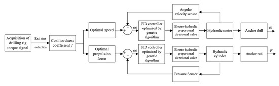
Figure 1.
The control strategy diagram of the adaptive rotary propulsion system of the air-borne bolting rig.
3. PID Controller Optimized by Genetic Algorithm
PID is the most mature and extensive control method in classical control theory. The control effect depends on the tuning and optimization of parameters. PID parameter tuning is a compromise between the rapidity and stability of system control. Because they are all empirical, it is difficult for traditional PID parameter tuning methods to take into account all indicators at the same time. Therefore, the PID controller designed is usually not optimal, and it is difficult to meet the requirements in actual control.
Genetic algorithm is adaptive probability algorithm for global optimization, which mimics the genetic mechanism of nature. Its theoretical basis is Darwin’s theory of evolution and survival of the fittest. According to the fitness function, the three genetic factors of replication, crossover and mutation are continuously modified. After a given genetic generation, the individual with the highest fitness is retained as the optimal value [29,30]. The main benefit of the genetic algorithm over other algorithms is that it avoids slipping into the local optimum solution. It has good global search capabilities, strong robustness, self-adaptability and the ability to find the global optimal solution without relying on initial conditions. It is so suitable for finding the optimal PID parameters to achieve optimal control. The solution process is shown in Figure 2.
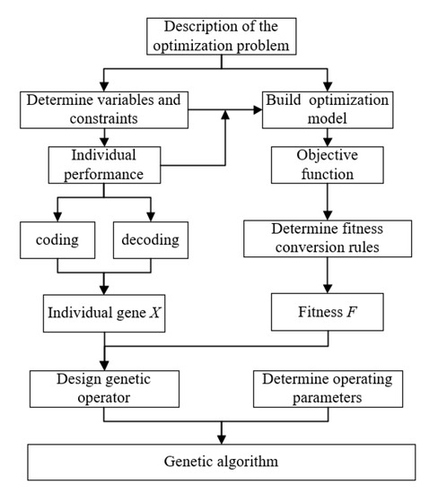
Figure 2.
Genetic algorithm for the optimal solution process.
3.1. Selection of Objective Function
The fitness function reflects the degree to which the seed in the genetic algorithm is close to the population optimum. This is an important indicator that directly affects the genetic algorithm. The essence of a genetic algorithm is to obtain the minimum value of the performance index after continuous optimization. Hence, we know that performance indicators will decrease when adaptability increases.
In order to reduce the error, this paper uses the objective function as the integral of the absolute value of the error. The objective function J is:
where e(t) is the systematic error.
3.2. Selection, Crossover and Mutation
The selection is based on the fitness of the new individual. Individuals with higher fitness have a higher chance of being selected, individuals with lower fitness have a lower chance of being selected:
where Fi is the fitness value of the i-th individual; hi is the probability that the i-th individual in each generation is selected.
Individual cumulative probability qi is:
The initial data can form a relatively optimized group through such a process. According to the crossover probability, two new individuals are generated by crossing two selected individuals. The primeval old individual is replaced by the new individual. The non-crossed individual is retained. The cross equation is:
where p1 and p2 are the individuals before crossing; c1 and c2 and the new individuals after crossing, respectively; a is the crossing probability, and the number between 0 and 1.
Mutation is based on the mutation probability to produce new individuals to join the population. The probability of mutation is usually 0.1. The mutation equation is:
where Cmax is the upper limit of gene cij; Cmin is the lower limit of gene cij; r is a random number from 0 to 1; g is the current evolutionary algebra; Gmax is the maximum evolutionary algebra.
Through a series of selection, crossover and mutation processes, the new generation of individuals differs from the first generation. They develop in the direction of population fitness from generation to generation. Because individuals with higher adaptability are always selected more often to produce the next generation, individuals with lower adaptability are more likely to be eliminated. This process repeats itself until the termination condition is met.
4. Modeling of the AMESim Hydraulic System of the Air-Borne Bolting Rig
4.1. Establishment of Hydraulic System Model of the Slewing System
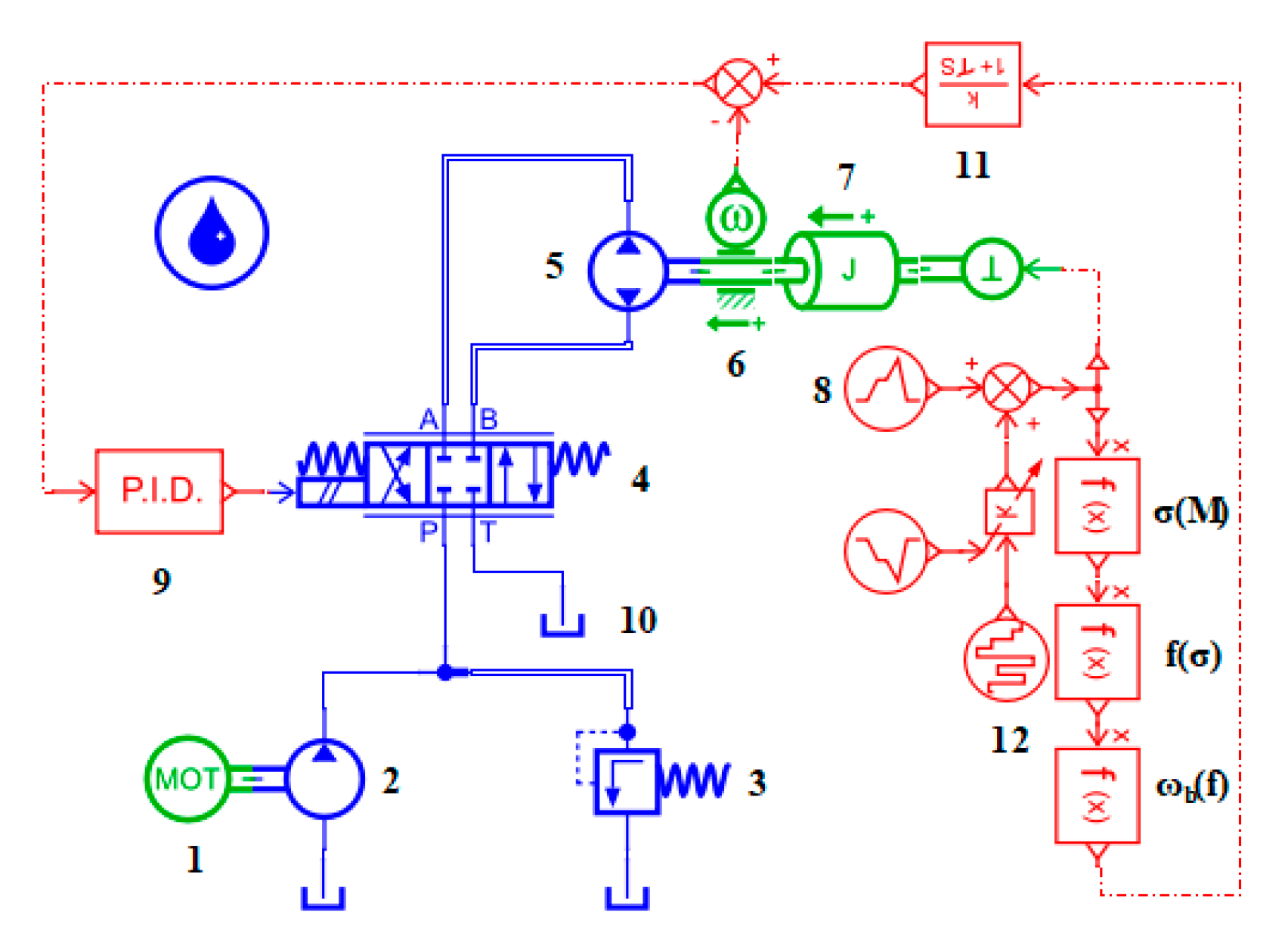
Rotary system of air-borne bolting rig is mainly composed of the hydraulic system and the electrical system [31]. The hydraulic system mainly consists of a hydraulic pump, a three-position four-way electro-hydraulic proportional reversing valve and a hydraulic motor. The hydraulic schematic diagram of AMESim is shown in Figure 3. The motor drives the hydraulic pump to extract hydraulic oil from the oil tank into the hydraulic system. The safety valve limits the working pressure of the rotary circuit to 16 MPa. The three-position four-way electro-hydraulic proportional directional valve adjusts the opening of the valve port according to the PID signal to regulate flow into the hydraulic motor. Finally, the rotation speed of the hydraulic motor is changed to realize the adaptive control of the rotation speed of the hydraulic motor. The parameters of each main component in the hydraulic slewing system are set as shown in Table 1.
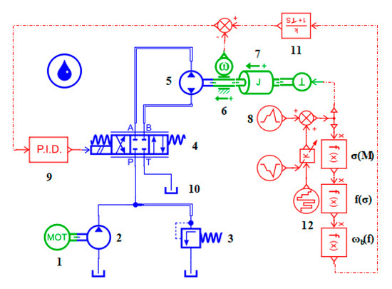
Figure 3.
AMESim hydraulic schematic diagram of the rotary system of the air-borne bolting rig. 1. Asynchronous motor; 2. Hydraulic pump; 3. Safety valve; 4. Three-position four-way electro-hydraulic proportional directional valve; 5. Hydraulic motor; 6. Angular velocity sensor; 7. Moment of inertia; 8. Load torque signal; 9. PID parameter controller; 10. Tank; 11. Low-pass filter; 12. Stochastic noise.

Table 1.
Parameter settings of main components of the slewing rotary model.
4.2. Establishment of the Hydraulic Model of Propulsion System
The propulsion system of the air-borne bolting rig is composed of a hydraulic pump, a safety valve, a three-position four-way electro-hydraulic proportional reversing valve, a hydraulic cylinder and other electrical components. The hydraulic schematic diagram of the AMESim is shown in Figure 4. The motor drives the hydraulic pump to pump the oil in the oil tank into the hydraulic circuit, and the safety valve stabilizes the pressure of the hydraulic system at 16 MPa. The PID controller controls the flow into the rodless cavity and the rod cavity of the hydraulic cylinder by sending the signal into the three-position four-way electro-hydraulic proportional reversing valve. Finally, the adaptive control of the propulsive force of the hydraulic cylinder is achieved. The parameters of each component in the hydraulic propulsion system are set as shown in Table 2.
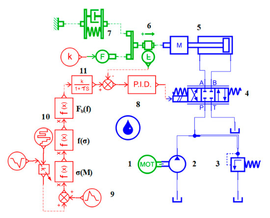
Figure 4.
Hydraulic schematic diagram of AMESim air-borne bolting rig propulsion system. 1. Asynchronous motor; 2. Hydraulic pump; 3. Safety valve; 4. Three-position four-way electro-hydraulic proportional directional valve; 5. Hydraulic cylinder with mass; 6. Pressure sensor; 7. Spring damping system; 8. PID parameter controller; 9. Load torque signal; 10. Stochastic noise; 11. Low-pass filter.
Table 2.
Parameter settings of the main components of the propulsion system model.
5. Simulation Experiment Results and Analysis
In the AMESim software, the adaptive control of the air-borne bolting rig is simulated according to the established hydraulic model of the air-borne bolting rig and the control above method. Compare the traditional PID and the GA-PID, the result of the rotation speed and propulsive force of the air-borne bolting rig is analyzed, and thus verify the superiority of the control strategy designed in this paper.
The outer diameter d of the rotary cutting drill selected in this paper is 27 mm. The inner diameter d0 is 7 mm. The drilling amount per revolution ∆ is 8 mm/r. The constant of cutting speed c is 8000 mm r/s. The proportional coefficient k is 4.
In the traditional PID, the PID parameters are selected by tuning rules based on ultimate parameters of the industrial process [32]. In the rotary system, the Kp, Ki, and Kd parameters are 0.66, 14.6, and 0.0198, respectively. In the propulsion system, the parameters of Kp, Ki, and Kd are 16.5, 47.1, and 1.93, respectively.
In the GA-PID, the population size is 100; the reproduction ratio is 0.8; the mutation probability is 0.1; the mutation amplitude is 0.2; the maximum generation is 20. In the speed control, the optimization range of Kp, Ki, Kd are set as [0, 1000]. After optimization by genetic algorithm, the parameters of Kp, Ki, and Kd are 998, 30, and 10, respectively. In the propulsion control, the optimization range of Kp, Ki, and Kd are [0, 500]. After optimization by genetic algorithm, Kp, Ki, and Kd are 493, 0.7, and 0.77, respectively.
5.1. Simulation of the Air-Borne Bolting Rig under a Single Coal Hardness
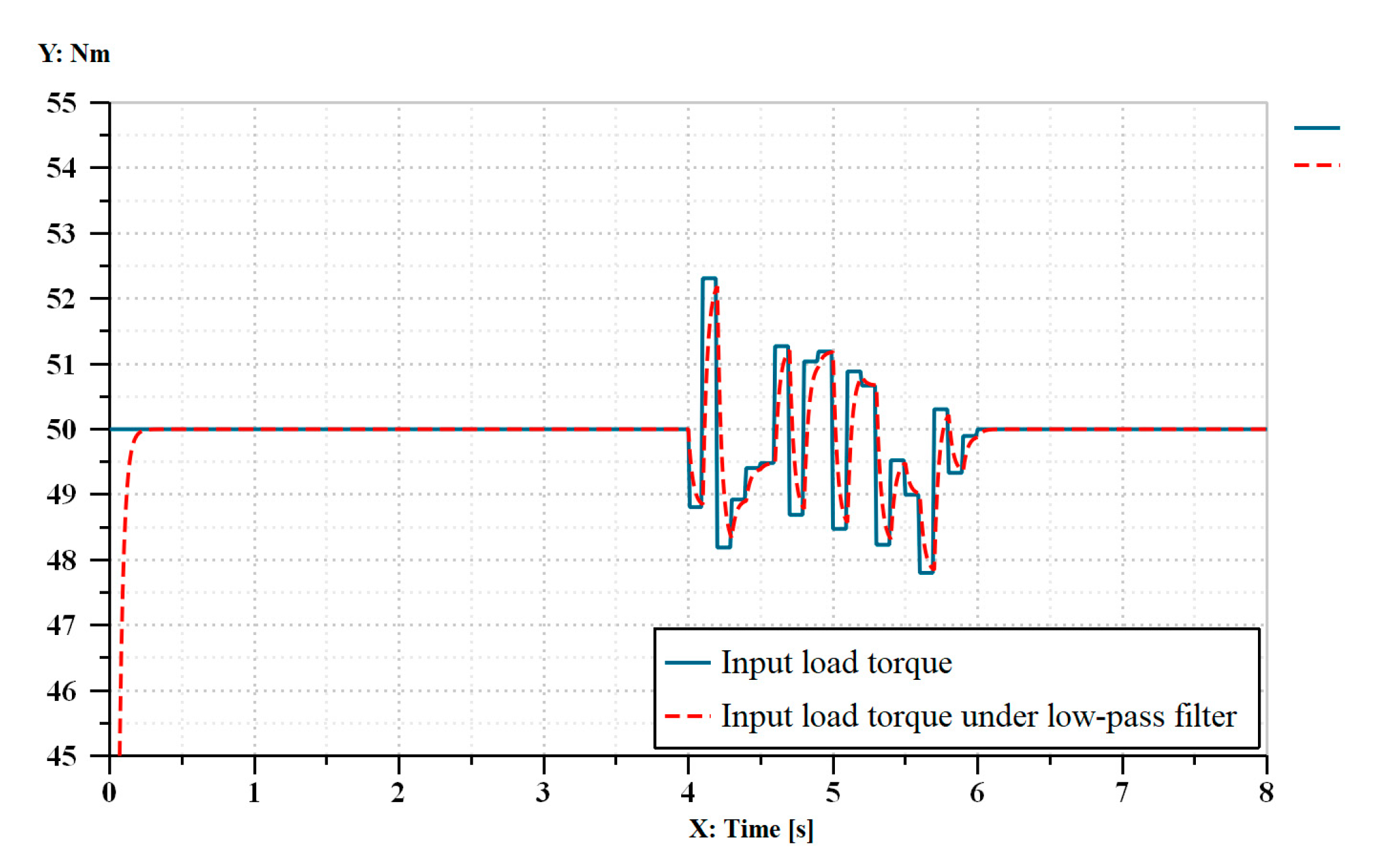
Under load conditions, input a 50 Nm torque signal to the system and add stochastic noise at 4 s, as shown in Figure 5. The traditional PID strategy and the GA-PID strategy are applied to the rotation speed and the propulsion control of the air-borne bolting rig, respectively. The sampling step is set to 0.01 s, and the simulation time is 8 s. The time constant of low-pass filter is 0.03 s.
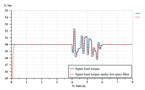
Figure 5.
The input torque signal under the single coal hardness.
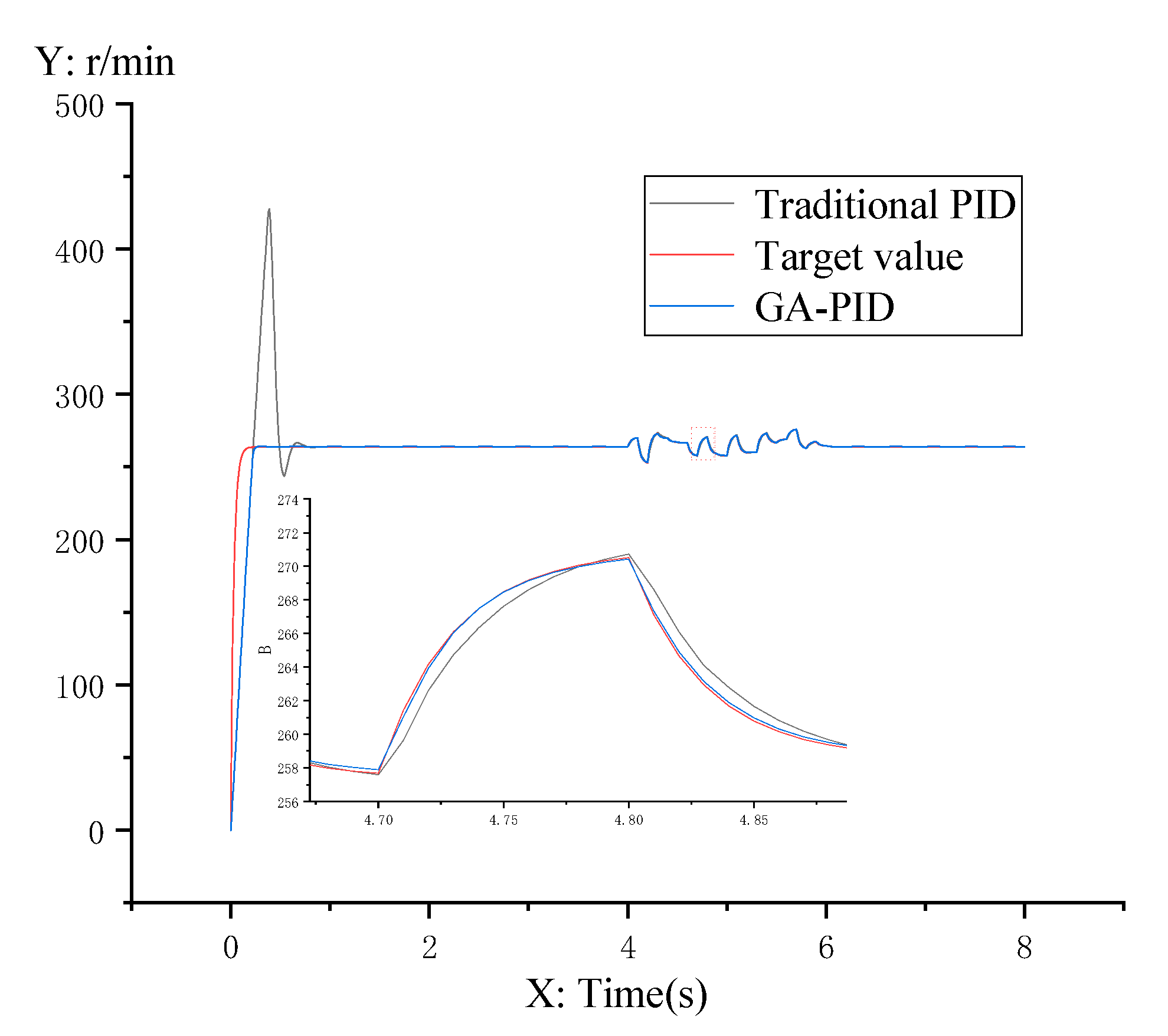
It can be seen from Figure 6 and Table 3 that the rotation speed of the air-borne bolting rig has been optimized by the PID controller optimized by the genetic algorithm under the condition of a single coal hardness. Compared with the traditional PID controller, the adjustment time of the system is reduced by 72.2%, the overshoot ratio is reduced by 99.7%, and the steady-state error is reduced by 62%. Thus, the GA-PID controller outperforms the traditional PID controller in any aspect.
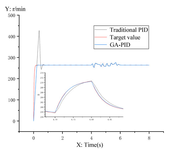
Figure 6.
Rotation speed control under the single coal hardness.
Table 3.
Simulation data of rotation speed under the single coal hardness.
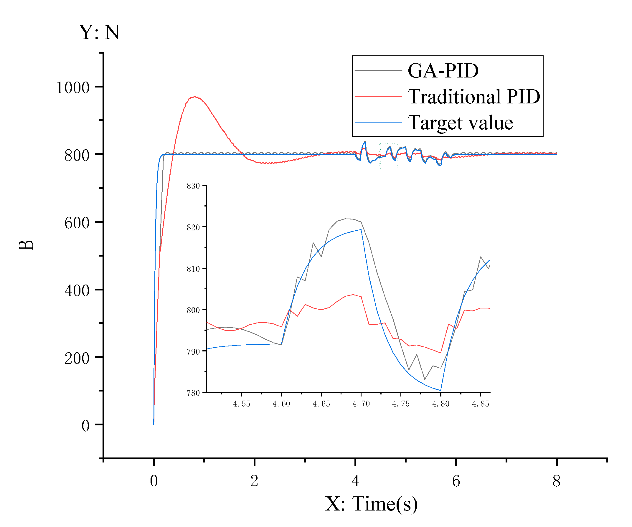
It can be seen from Figure 7 and Table 4 that the propulsive force of the air-borne bolting rig is optimized by the genetic algorithm under the condition of a single coal hardness. Compared to traditional PID, the adjustment time of the system is reduced by 92.5%, the overshoot ratio is reduced by 97%, and the steady-state error is reduced by 83.3%. It can be concluded that optimizing PID parameters through the genetic algorithm allows the system to reach the target value rapidly and accurately.
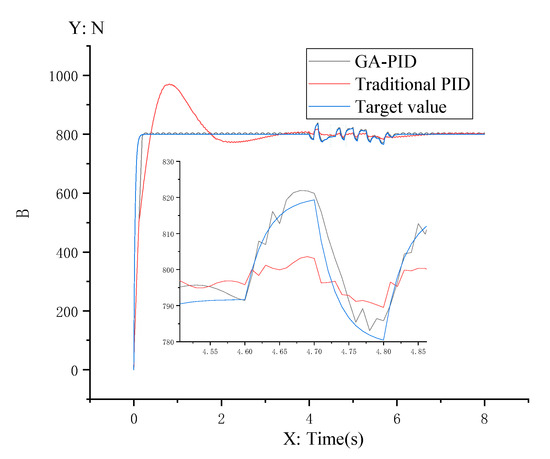
Figure 7.
Propulsion control under the single coal hardness.
Table 4.
Simulation data of propulsive force under the single coal hardness.
5.2. Simulation of the Air-Borne Bolting Rig under the Coal Hardness of Sudden Change
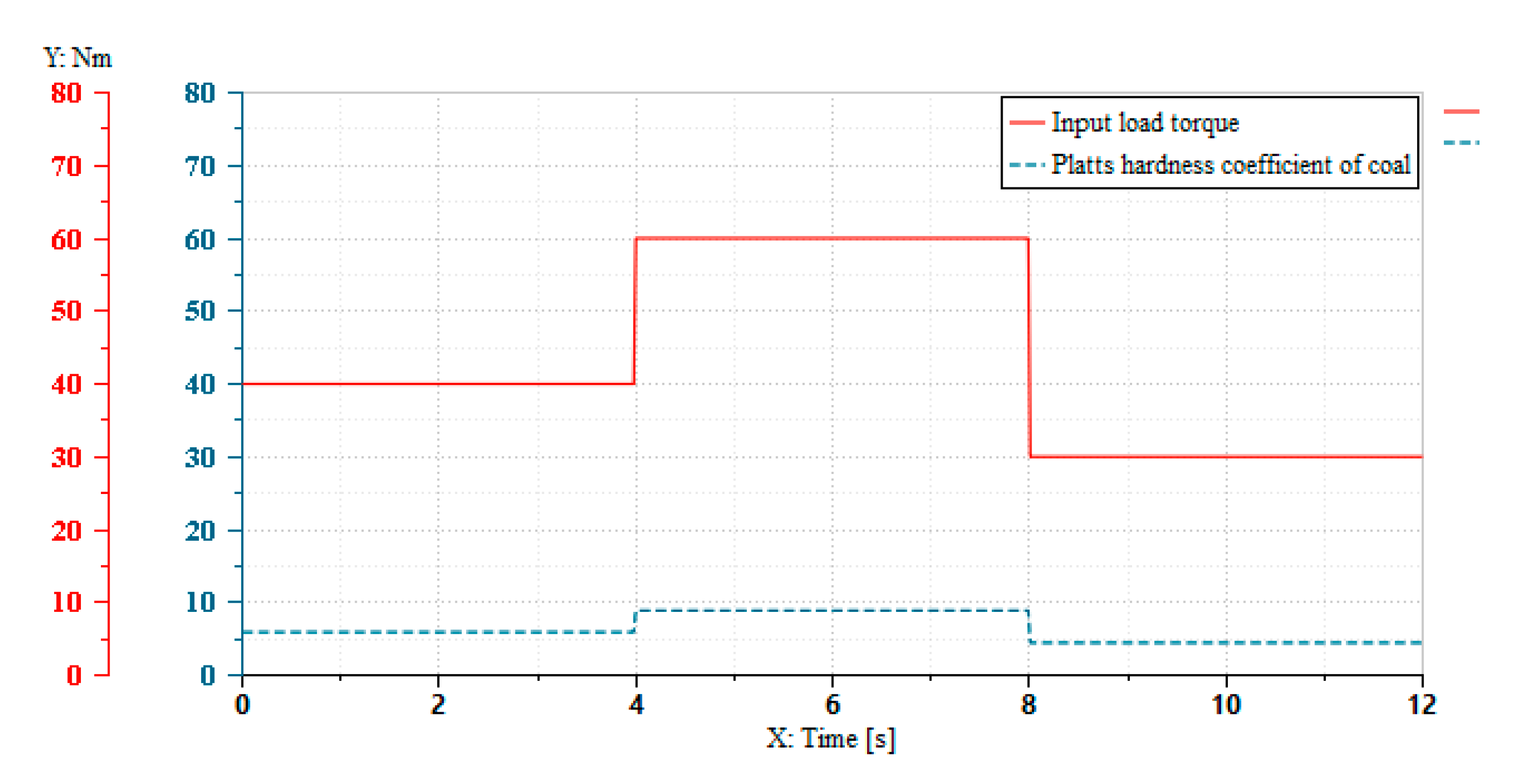
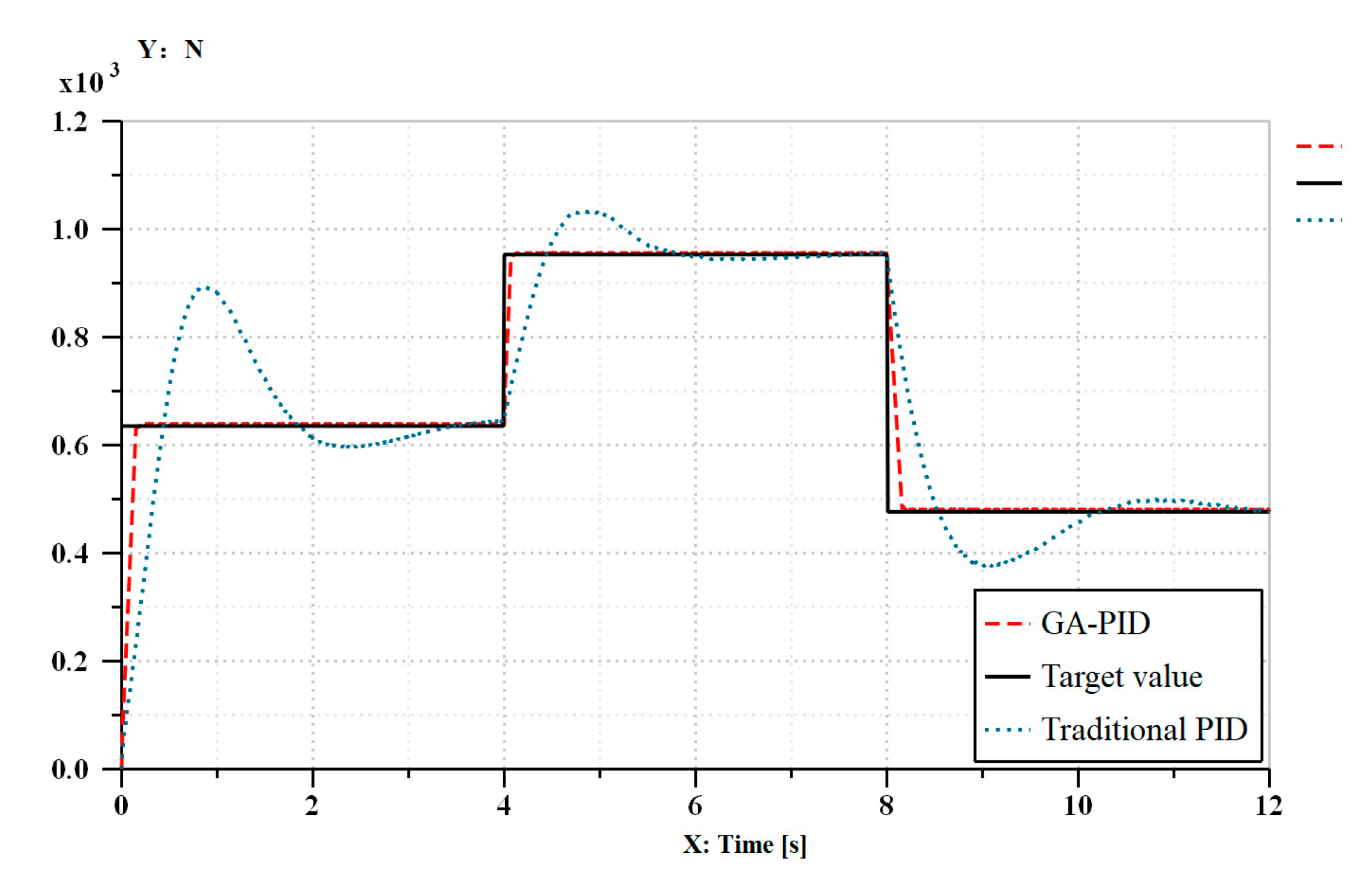
As illustrated in Figure 8, under load conditions, the system inputs 40 Nm torque from 0 s to 4 s, inputs 60 Nm torque from 4 s to 8 s and inputs 30 Nm torque from 8 s to 12 s. The traditional PID and the GA-PID are applied to control the rotation speed and propulsive force of the air-borne bolting rig, respectively. The sampling step is set to 0.01 s, and the simulation time is 12 s.
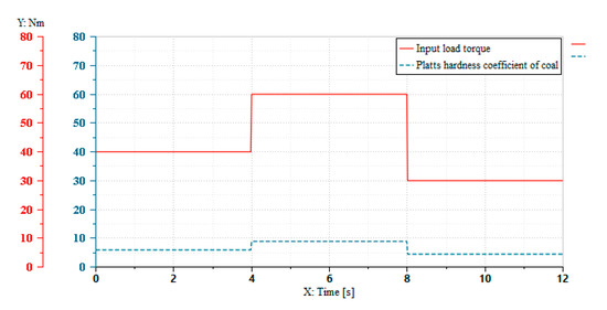
Figure 8.
The input torque signal and corresponding coal hardness coefficient under the coal hardness of sudden change.
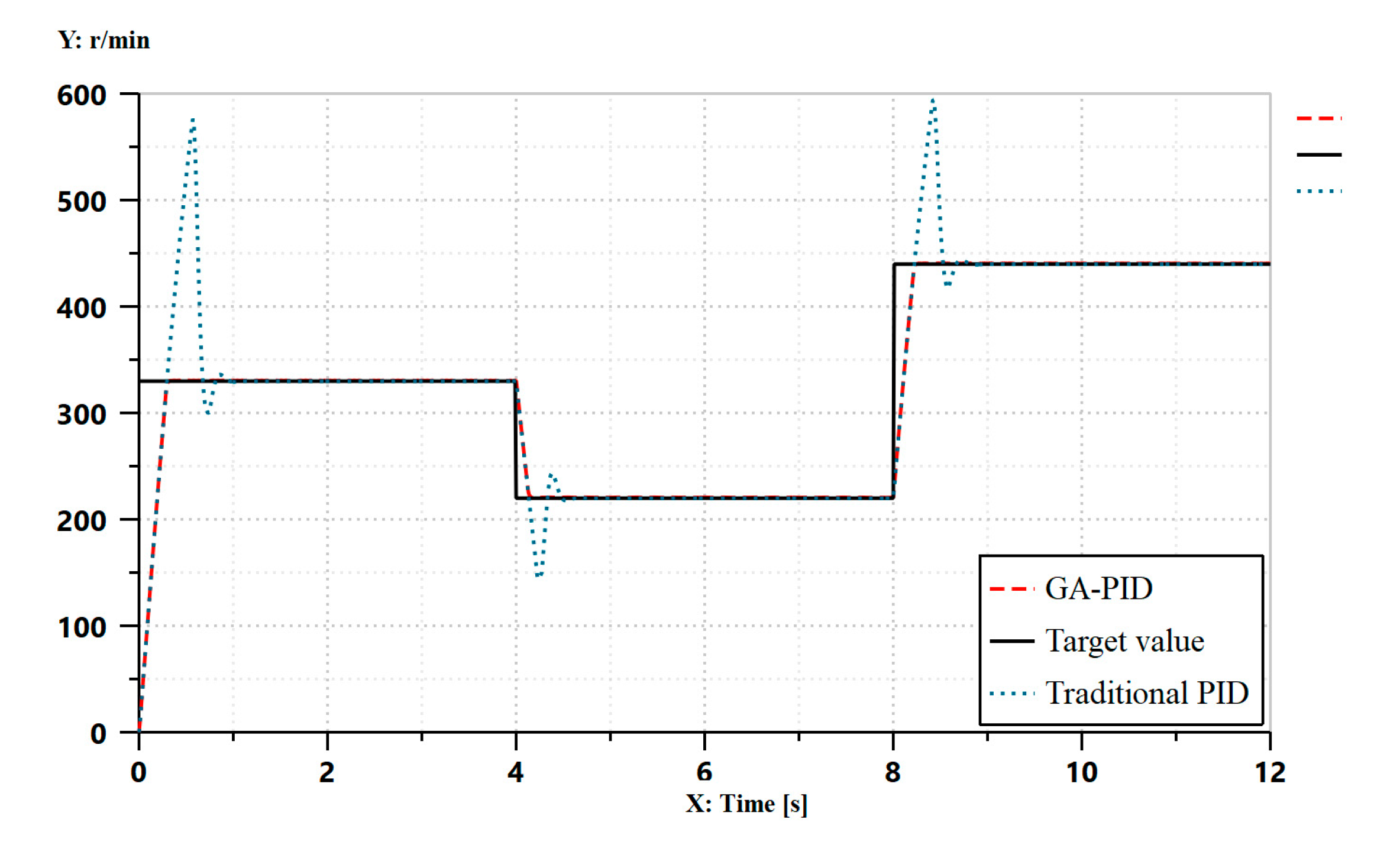
It can be seen from Figure 9 and Table 5 that the performance of GA-PID is still better than that of traditional PID in the rotation speed control of coal hardness of sudden change. The adjustment time of the system is decreased by 63.6% compared to the traditional PID controller, the overshoot ratio is reduced by 99.7% compared to the traditional PID controller, and the steady-state error is reduced by 5% compared to the traditional PID controller.
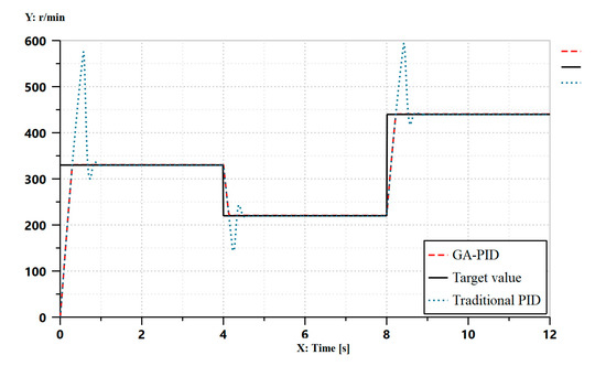
Figure 9.
Rotation speed control under the coal hardness of sudden change.
Table 5.
Simulation data of rotation speed under the coal hardness of sudden change.
It can be seen from Figure 10 and Table 6 that the genetic algorithm is used to optimize the propulsive force of the air-borne bolting rig under the condition of abrupt change of coal hardness. Compared to the traditional PID, the adjustment time of the system is reduced by 94%, the overshoot ratio is reduced by 98%, and the steady-state error is reduced by 45.7%.
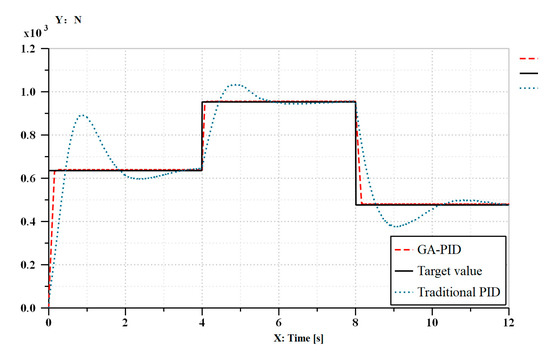
Figure 10.
Propulsion control under coal hardness of sudden change.
Table 6.
Simulation data of propulsive force under coal hardness of sudden change.
The above comparison reveals that the GA-PID has lower overshoot, faster response speed and better robustness than the traditional PID. It has a satisfactory effect to fulfill the system’s real-time requirements.
6. Analysis and Conclusions
After studying the drilling performance of air-borne bolting rig, it is found that the hardness of coal has a significant impact on the cutting performance. When the coal hardness is too high, the speed should be reduced, and the propulsive force should be increased to maximize the efficiency of the air-borne bolting rig. When the coal hardness is too low, the speed should be increased to reduce the propulsive force.
In the paper, we use the GA-PID and the traditional PID to control the rotation speed and propulsive force of the drilling rig under the condition of single coal hardness and coal hardness of sudden change. It was found that the GA-PID had smaller the rise time, adjustment time, overshoot of the system and the steady-state error of the system than traditional PID. The control method allows the rotation speed and propulsive force of the air-borne bolting rig to automatically adjust the hardness of coal, ensuring the realization of adaptive control.
Author Contributions
Conceptualization, Q.L. and Y.Z.; methodology, Y.Z. and T.L; software, Y.Z.; validation, Q.L., T.L. and C.L.; formal analysis, Y.Z.; investigation, Y.Z.; resources, Q.L.; writing—original draft preparation, Y.Z.; writing—review and editing, T.L. All authors have read and agreed to the published version of the manuscript.
Funding
This research was funded by Anhui Science and Technology Major Project (201903a05020029), the University Synergy Innovation Program of Anhui Province (GXXT-2019-048) and Open Project of Anhui Province Key Laboratory of Special and Heavy Load Robot (TZJQR006-2021).
Institutional Review Board Statement
Not applicable.
Informed Consent Statement
Not applicable.
Conflicts of Interest
The authors declare no conflict of interest.
References
- Jamal, R.; Sair, K.; Ali, N.; Craig, C. Rock characterization while drilling and application of roof bolter drilling data for eval-uation of ground conditions. J. Rock Mech. Geotech. Eng. 2015, 7, 273–281. [Google Scholar]
- Ove, S. Rock bolting: Theory and Application in Mining and Underground Construction. In Proceedings of the International Symposium, Abisko, Sweden, 28 August–2 September 1983; CRC Press: Boca Raton, FL, USA, 2021. [Google Scholar]
- Li, K.; Di, Z. Discussion on technical problems and development suggestions of engineering drilling rig automation. Front. Mechatron. Eng. 2020, 2, 49–52. [Google Scholar] [CrossRef]
- Yao, K. Research and development of intelligent drilling rig in coal mine and discussion on problems. In Proceedings of the 7th Academic Conference of Geology Resource Management and Sustainable Development, Beijing, China, 28–29 December 2019; pp. 223–227. [Google Scholar] [CrossRef]
- Chen, A.; Wang, Q.; Chen, Z.; Chen, J.; Chen, Z.; Yang, J. Investigating pile anchor support system for deep foundation pit in a congested area of Changchun. Bull. Int. Assoc. Eng. Geol. 2021, 80, 1125–1136. [Google Scholar] [CrossRef]
- Wang, F.; Gong, G.; Qin, Y.; Sun, C.; Yang, H. A novel cutterhead cascade control strategy for hybrid-driving tunnel boring machines. Proc. Inst. Mech. Eng. Part I J. Syst. Control. Eng. 2020, 234, 922–936. [Google Scholar] [CrossRef]
- Katz, Z.; Poustie, A. On the hole quality and drill wandering relationship. Int. J. Adv. Manuf. Technol. 2001, 17, 233–237. [Google Scholar] [CrossRef]
- Oh, J.-Y.; Lee, G.-H.; Kang, H.-S.; Song, C.-S. Modeling and performance analysis of rock drill drifters for rock stiffness. Int. J. Precis. Eng. Manuf. 2012, 13, 2187–2193. [Google Scholar] [CrossRef]
- Antonenkov, D.V.; Manusov, V.Z.; Tsarev, R.Y. Improvement of rock crushing quality based on load specifications set for electrically-driven hydraulic drilling rigs. IOP Conf. Series Mater. Sci. Eng. 2019, 560. [Google Scholar] [CrossRef] [Green Version]
- Wang, Y.; Yun, J.; Wei, T.; Zhang, T. Typical circuit performance analysis of multi-station tunnel drilling machine’s hydraulic system. J. Mechatron. 2013, 1, 73–79. [Google Scholar] [CrossRef]
- Jiang, H.; Luo, Y. Development of a roof bolter drilling control process to reduce the generation of respirable dust. Int. J. Coal Sci. Technol. 2021, 1–6. [Google Scholar] [CrossRef]
- Yang, S.G.; Li, L.; Lu, L.J. Static and dynamic characteristics of a novel mine roofbolter driven by non-circular planetary gear hydraulic motor. China J. Mech. Eng. 2015, 36, 333–340. [Google Scholar]
- Liu, Z.; Wang, H.; Xiong, Z.; Huo, J.; Zhan, J.; He, Y. Modeling and research of fuzzy PID control strategy for hydraulic rock drill propulsion system. J. Phys. Conf. Ser. 2021, 1820, 1–9. [Google Scholar] [CrossRef]
- Wu, W.R.; Xu, Z. Mechanical mechanics and application of high speed on/off valve to feeding system of hydraulic drilling rig. Adv. Mater. Res. 2014, 908, 330–334. [Google Scholar] [CrossRef]
- Liu, G.; Zhang, Y.; Cao, X. Research on automatic bit feeding control system with constant weight on bit based on fuzzy predictive control. J. Phys. Conf. Ser. 2021, 1894, 1–9. [Google Scholar] [CrossRef]
- Khadisov, M.; Hagen, H.; Jakobsen, A.; Sui, D. Developments and experimental tests on a laboratory-scale drilling automation system. J. Pet. Explor. Prod. Technol. 2019, 10, 605–621. [Google Scholar] [CrossRef] [Green Version]
- Anjum, Z.; Guo, Y.; Yao, W. Fault tolerant control for robotic manipulator using fractional-order backstepping fast terminal sliding mode control. Trans. Inst. Meas. Control. 2021, 43, 3244–3254. [Google Scholar] [CrossRef]
- Gupta, M.K.; Kumar, R.; Verma, V.; Sharma, A. Robust control based stability analysis and trajectory tracking of triple link robot manipulator. J. Eur. Systèmes Autom. 2021, 54, 641–647. [Google Scholar] [CrossRef]
- Li, J.; Wang, S.; Wang, J.; Li, J.; Zhao, J.; Ma, L. Iterative learning control for a distributed cloud robot with payload delivery. Assem. Autom. 2021, 41, 263–273. [Google Scholar] [CrossRef]
- Tian, K.; Xiao, Z.; Ji, P. Optimization and simulation of DMC algorithm with terminal weight based on LQR controller. J. Phys. Conf. Ser. 2021, 1961, 012044. [Google Scholar] [CrossRef]
- Bai, S.; Liu, Z.; Wang, J. Research on the dynamics of geological drilling rig against drill pipe impact. Shock Vib. 2021, 2021, 1–10. [Google Scholar] [CrossRef]
- The Driller, New PowerROC Quarrying Rig Saves on Fuel Consumption. 2017, 38. Available online: https://www.thedriller.com/articles/90779-new-powerroc-quarrying-rig-saves-on-fuel-consumption (accessed on 14 October 2021).
- Yang, L.; Guo, Y.; Liu, C. A comprehensive prediction model of rock strength and its application on classifying the rock during the drilling. Adv. Appl. Sci. 2020, 5, 82. [Google Scholar] [CrossRef]
- Zhou, B.; Yang, Y.; Yang, K.M.; Dong, Y.B. Analysis and research of hydraulic roof bolter in performance testing. Appl. Mech. Mater. 2015, 733, 607–610. [Google Scholar] [CrossRef]
- Biryukov, I.M. Roller-Bit Drilling in Mining; Gosgortekhizdat: Moscow, Russia, 1962. [Google Scholar]
- Alimov, O.D.; Dvornikov, L.T. Methods of rotary borehole drilling. J. Min. Sci. 1965, 1, 250–254. [Google Scholar] [CrossRef]
- Zhou, X.; Li, D.; Zhang, L.; Duan, Q. Application of an adaptive PID controller enhanced by a differential evolution algorithm for precise control of dissolved oxygen in recirculating aquaculture systems. Biosyst. Eng. 2021, 208, 186–198. [Google Scholar] [CrossRef]
- Ma, D.; Chen, J.; Chai, T. Role of integral control for enlarging second-order delay consensus margin under PID protocols: None. IEEE Trans. Cybern. 2021, 1–11. [Google Scholar] [CrossRef]
- Jordán, J.; Palanca, J.; del Val, E.; Julian, V.; Botti, V. Localization of charging stations for electric vehicles using genetic algorithms. Neurocomputing 2021, 452, 416–423. [Google Scholar] [CrossRef]
- Wang, X.; Zhu, S.; Zeng, Q.; Guo, X. Improved multi-objective Hybrid Genetic Algorithm for shape and size optimization of free-form latticed structures. J. Build. Eng. 2021, 43, 102902. [Google Scholar] [CrossRef]
- Fang, P.; Zhang, R.; Chen, X.; Hu, Y.; Meng, R. Application and development of electro hydraulic automatic control technology in drilling equipment. In Proceedings of the 8th Academic Conference of Geology Resource Management and Sustainable Development, Beijing, China, 19 December 2020. [Google Scholar]
- Chau, P.C. Stability of Closed-Loop Systems; Cambridge University Press (CUP): Cambridge, UK, 2002; pp. 129–146. [Google Scholar]


Publisher’s Note: MDPI stays neutral with regard to jurisdictional claims in published maps and institutional affiliations. |
© 2021 by the authors. Licensee MDPI, Basel, Switzerland. This article is an open access article distributed under the terms and conditions of the Creative Commons Attribution (CC BY) license (https://creativecommons.org/licenses/by/4.0/).