Article

Integral Modeling for Deviation Correction Trajectory of the Mechanical Vertical Drilling System

1
School of Engineering and Technology, China University of Geosciences, Beijing 100083, China
2
Key Laboratory of Deep Geological Drilling Technology, Ministry of Natural Resources, Beijing 100083, China
*
Author to whom correspondence should be addressed.
Machines 2021, 9(8), 161; https://doi.org/10.3390/machines9080161
Submission received: 9 July 2021 / Revised: 4 August 2021 / Accepted: 5 August 2021 / Published: 9 August 2021
(This article belongs to the Special Issue Dynamics and Diagnostics of Heavy-Duty Industrial Machines)

Abstract

:
The deviation correction trajectory of the mechanical vertical drilling system (MVDS) is very important because it is the final embodiment of performance. However, it is impossible to obtain it at the design stage, except when using simulation methods. In this paper, tool face angle model and other theoretical models were established, respectively, and the trajectory simulation method was created through model coupling. Next, the method was used to simulate the trajectory of MVDS under two typical working conditions. The results indicate that the critical deviation angle is the deviation control accuracy of the MVDS. The existence of critical deflection angle makes MVDS correct deviation and change azimuth at the same time, resulting in the trajectory being a three-dimensional curve, which has the tendency of drifting to the left. Furthermore, the deviation and azimuth change rate are constantly changing in the process of drilling. The results also show that the MVDS is unable to correct the horizontal displacement of the downhole. The proposed method and analysis results are helpful to find out and solve the problem of the current design as soon as possible, and to provide guidance for the subsequent structure optimization.

1. Introduction

Automatic vertical drilling technology is a kind of vertical well drilling technology which uses downhole drilling tools to prevent and correct deviation. It integrates the characteristics of the packed hole assembly and the pendulum assembly. This technology originated from the German continental deep drilling program (Kontinentales Tiefborh programm der Bundesrepublik Deutschland, KTB) in 1988. Due to the application of vertical drilling technology, the KTB well became the most vertical borehole in the world at that time [1,2,3,4]. As the originator of rotary steering technology, the automatic vertical drilling technology has the same steering principle as the rotary steering technology [5]. In recent years, with the progress of rotary steering technology, the automatic vertical drilling technology has been developed rapidly [6,7].
As the core technology of vertical drilling, the automatic vertical drilling system is mainly composed of two parts: one is the stable platform, the other is the actuator, as shown in Figure 1. The stable platform is a dynamic stability control system, which controls the deviation measurement and correction of vertical drilling system. The function of the actuator is to respond to the control signal of the stable platform, and provide the force required by the deviation correction for the drill bit. If the stable platform is regarded as the “brain” of the automatic vertical drilling system, the actuator can be viewed as the “limbs” of the vertical drilling system [8].
According to the structure of stable platform, the vertical drilling system can be divided into electric control vertical drilling system (EVDS) and mechanical vertical drilling system (MVDS). The EVDS uses a three-axis accelerometer and fluxgate to detect well deviation, while the MVDS uses gravity moment of eccentric block to sense well deviation. Compared with the EVDS, the MVDS has a relatively low deviation control accuracy, but it possesses a simple structure without any electronic components, which can reduce the sealing requirements of drilling tools. In addition, the MVDS has many advantages, such as low manufacturing cost, high reliability, high temperature resistance, and greater impact resistance [9,10]. Therefore, the MVDS has a better application prospect in the future and the key problem we are facing is the improvement of its deviation correction performance.
The deviation correction performance of MVDS is ultimately reflected by the trajectory formed in the inclined formation, and the only way to obtain the trajectory is to measure after drilling. However, this is impossible in the design stage. In order to verify the actual deviation correction ability of the tool and analyze the correlation between the design parameters and the performance, it is necessary to establish the deviation correction trajectory simulation method before the tool is put into the downhole testing. Only in this way can the working characteristics of the current tool in the downhole environment be obtained and further understood during the course of design, which is helpful to find out the existing problems of the current design as soon as possible and provide ideas for the subsequent structure optimization.
At present, there are relatively few researches on the MVDS because of its relatively short history [11]. For commercial confidentiality, most of the research results published by some international oil service companies were only about the technical parameters and application effects of their products. At the same time, some scholars in universities have done some research on MVDS. For the stable platform, Wang et al. have used experimental methods to study the variation of friction performance between the upper and lower plate valves under different working conditions [12]. Li et al. have derived the stable position model of the eccentric block and investigated the dynamic characteristics of it under the effect of torsional vibration by using multi-body dynamics simulation method [13]. For the actuator, Zhang have studied the output characteristics of the pushing force through experimental methods [14]. Besides, the influence of the pushing force on the drill string dynamics have been studied through theoretical derivation by Xue et al. [15,16]. In addition, Liu and Zahra [17,18] have optimized the trajectory control and measurement of the EVDS and RSS (Rotary steerable system). Elrayah et al. have researched the mechanical problems of drilling string related to the trajectory [19,20]. In summary, there are three main aspects to be improved.
  • The current research on MDVS mainly focuses on the mechanical characteristics of the stable platform or actuator separately. Coupling the action mechanism of the above two to simulate the deviation correction trajectory of drilling tool has not been conducted.
  • The stable position model is based on the principle of static moment balance and the influence of inertia and acceleration is ignored.
  • The methods of trajectory control and measurement cannot be applied to MVDS because it cannot realize artificial control at present.
In order to realize the well trajectory simulation of MVDS, this paper obtains the model of equivalent pushing force and tool face angle by the theoretical mechanics method. After coupling them with the subsequent established models, the deviation correction trajectory is extrapolated by cyclic iteration, thus the trajectory simulation of the MVDS under two typical working conditions is realized.

2. Working Principle

The working principle of MVDS is shown in Figure 2. In the drilling process, the lower plate valve rotates synchronously with the bit. The upper plate valve is fixed with the eccentric block of the stable platform circumferentially through the connecting key. The eccentric block is isolated from the shell by the bearing so that it can rotate freely around the tool center. When well deviation occurs, the eccentric block drives the upper plate valve to rotate to the lower side of the borehole under the effect of gravity. Therefore, the arc hole on the upper plate valve, which is opposite the eccentric block, can be located at the upper side of the borehole. When one of the flow channels on the lower plate valve rotates to the upper side of the borehole, it will be connected with the arc hole. At this moment, the high-pressure drilling fluid will flow in the connected channel and impel the corresponding steering rib of the actuator to push against the upper side of the wellbore, so as to make the bit produce side cutting force for deviation correction. When the flow channel rotates away from the upper side of the borehole, the drilling fluid pressure in the steering rib decreases, and the steering rib returns to the position before pushing out. The above behavior is a continuous cycle process, hence the periodic pushing force can be produced at the upper side of the borehole. By using the above working principle, MVDS is able to correct the deviated well or ensure the verticality of the vertical well.
As the kernel component of the stable platform, the eccentric block determines the pushing direction of the steering rib, hence its parking position directly affects the extension direction of the wellbore trajectory. When MVDS is working, the lower plate valve rotates with the bit. Because the upper plate valve closely fits with the lower plate valve under the mud pressure, the eccentric block fixed with the upper plate valve is disturbed by the friction torque between the upper plate valve and the lower plate valve at the same time. In addition, it is also disturbed by the bearing friction torque generated by the shell rotation. The above friction torques make the eccentric block unable to stop at the lower side of the borehole, but deflects a certain angle to overcome the friction torque. As a result, there is a critical deflection angle between the parking position and the lower side of the borehole (as shown in Figure 3). The existence of the critical deflection angle makes the angle difference between the pushing force direction and the lower side direction of the borehole, which will lead to the bit being subjected to both the force of deviation correction and the force of azimuth variation. In addition, the formation’s anisotropy and dip angle will cause azimuth drift and natural deflecting. Therefore, the drilling trajectory of MVDS is a complex three-dimensional curve, which is not only influenced by the tool itself, but also by the external environment.

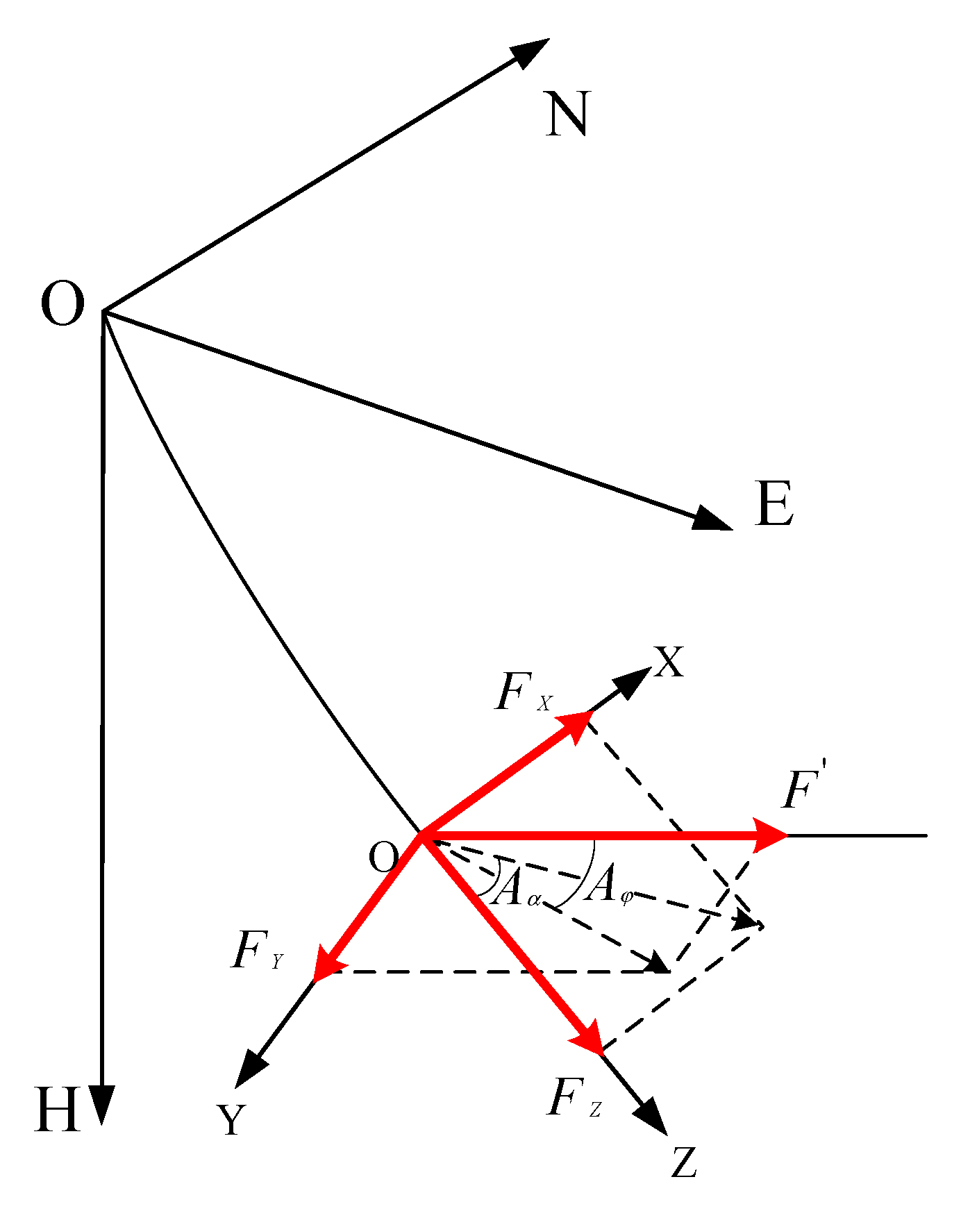
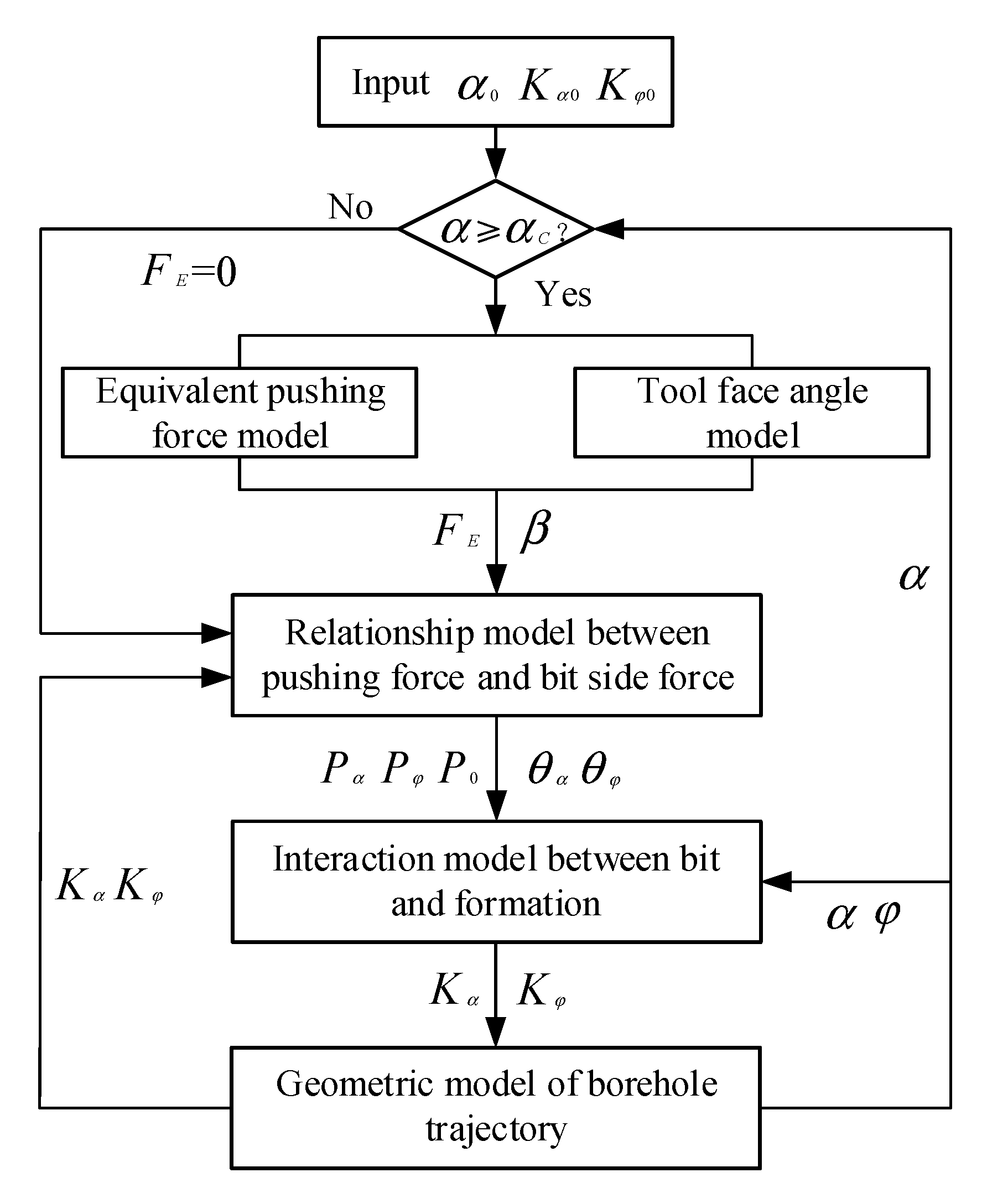
3. Mathematical Model

The establishment of deviation correction trajectory is a process in which bit interacts with formation and extends forward after being subjected to WOB (Weight on bit), torque, side cutting force, and constraint of borehole, so it is related to the dynamic characteristics of stable platform and actuator, structure, and stress of BHA (Bottom hole assembly), drilling process parameters, wellbore geometric parameters, bit characteristics, and formation characteristics. Therefore, in order to realize deviation correction trajectory simulation of MVDS, it is necessary to establish equivalent pushing force model, tool face angle model, relationship model between pushing force and bit side force, interaction model between bit and formation, and borehole trajectory geometry model, respectively. They are then coupled to get the deviation correction trajectory simulation method. Principle hypotheses are as follows.
  • The dynamic pushing force of MVDS is equivalent to the static pushing force.
  • Treat the components of the stable platform as rigid bodies.
  • Ignore the swing process of eccentric block before it is stabilized.
  • Ignore the influence of bearing friction.
  • Ignore the influence of the holes on the upper and lower plate valves.
  • BHA is regarded as a small deformation elastomer.

3.1. Equivalent Pushing Force Model

The deviation correction effect of MVDS depends on the periodic pushing against the wellbore by the steering rib. In each pushing cycle, the direction of the pushing force is constantly changing. Since the bit footage in each pushing cycle is very small, the dynamic pushing force will only cause a certain degree of hole enlargement, and will not bring about the left and right swing of the hole azimuth. In order to facilitate the analysis, the dynamic pushing force obtained by sliding and pushing against the wellbore can be simplified as a static equivalent pushing force [21]. Due to the symmetry of the dynamic pushing force, the static equivalent pushing force can be applied to the center line direction of the arc hole, as shown in Figure 4. The equivalent pushing force represents the average pushing force on the drilling tool in a cycle when BHA rotates at a constant speed. The force is obtained by the principle of equal deviation correction impulse. The solution process is as follows [21].
F E T P = F E θ A ω = θ A / 2 θ A / 2 F P cos θ d θ ω
wherein, F E —Equivalent pushing force (N), T P —Pushing time of steering rib in a cycle (s), θ A —Opening angle of arc hole (Rad), ω —BHA angular velocity (Rad/s), F P —Reaction force of steering rib pushing against wellbore (N). The equation of equivalent pushing force can be obtained by solving Equation (1) (as shown in Equation (2)).
F E = 2 F P sin θ A 2 θ A
MVDS is usually designed with three steering ribs. In order to make the pushing force continuous and uninterrupted, the opening angle of the arc hole of the upper plate valve is usually designed as 120°. Therefore, the equivalent pushing force is shown in Equation (3).
F E = 3 3 2 π F P

3.2. Tool Face Angle Model

The tool face angle of MVDS determines the direction of the bit extending to the formation at the next moment. According to the equivalent pushing force model of MVDS, the tool face of MVDS is the plane formed by the direction line of equivalent pushing force and the center line of tool. As the eccentric block is opposite to the arc hole of the upper plate valve, the calculation equation of MVDS tool face angle is shown in Equation (4) according to the definition of tool face angle of high side mode.
β = π + θ C
wherein, β —Tool face angle of MVDS (Rad), θ C —Critical deflection angle of eccentric block (Rad).
Therefore, after the critical deflection angle model is deduced, the tool face angle model of MVDS can be obtained from Equation (4). When MVDS is working, the eccentric moment caused by gravity, the friction torque caused by the friction between upper and lower plate valves, and the friction torque of bearing are simultaneously exerted on the eccentric block. Because the friction coefficient of ball bearing is small, the friction torque of bearing is very small in comparison with the eccentric moment and the friction torque of plate valve [22]. Therefore, the influence of bearing friction torque is ignored in the analysis, and only the influence of eccentric moment and friction torque of the plate valve on deflection behavior of eccentric block is discussed. The eccentric moment is the active torque, and the friction torque of the plate valve is the interference torque. Both of them determine the critical deflection angle.
In order to obtain the eccentric moment, it is necessary to get the radial position of the gravity center G. A plane rectangular coordinate system is established on the cross section of the eccentric block. Since the eccentric block is usually symmetrical, the center of gravity is located on the Y axis (as shown in Figure 5a). The Y coordinate value of the gravity center can be obtained by using Equation (5) [13].
Y C = A y d A A d A = 4 ( r 2 3 r 1 3 ) sin ( α 2 α 1 2 ) 3 ( r 2 2 r 1 2 ) ( α 2 α 1 )
wherein, r 1 ,   r 2 —Inner and outer radius of eccentric block (mm), α 1 , α 2 —Angle between both sides of the eccentric block and X-axis (Rad).
The gravity of the eccentric block can be obtained by Equation (6).
F G = ρ v g = α 2 α 1 2 ρ g l ( r 2 2 r 1 2 )
wherein, F G Gravity of eccentric block (N), ρ Density of eccentric block (kg/mm3), v Volume of eccentric block (mm3), g Acceleration of gravity (m/s2), l —Length of eccentric block (mm).
It can be seen from Figure 5b that the gravity of the eccentric block can be decomposed into three mutually perpendicular components ( F x ,   F Y ,   F Z ) in space. Because F Y ,   F Z , and the rotation axis of the eccentric block are in the same plane, the moment of these two forces on the rotation axis is zero, so there is only component force F x can produce moment on the rotation axis of the eccentric block, and its value is shown in Equation (7).
T E = F G sin α sin θ Y C = 2 3 ρ g l ( r 2 3 r 1 3 ) sin ( α 2 α 1 2 ) sin α sin θ
wherein, T E Eccentric moment of eccentric block (N·m), α Inclination angle (Rad), θ —The deflection angle of the eccentric block relative to the lower side of the borehole (Rad).
It can be seen from Equation (7) that, in order to make the eccentric moment of the eccentric block reach the maximum under a certain tool diameter, we can set r 1 as 0, α 1 as 0, α 2 as π , and the cross section of the eccentric block is semicircular. Therefore, the eccentric moment can be obtained as shown in Equation (8).
T E = 2 3 ρ g l r 2 3 sin α sin θ
The upper and lower plate valves of MVDS are usually designed to be circular, and the friction torque of the plate valve can be obtained by integral method after ignoring the influence of the holes on the upper and lower plate valves.
T p = 0 r P 2 μ P P π r 2 d r = 2 3 π μ P P r P 3
wherein, T p —Friction torque between plate valves (N·m), r P —Outer diameter of plate valve (mm), μ P Friction coefficient between plate valves, P —Pressure between plate valves (MPa).
According to the principle of statics balance, when the eccentric moment of the eccentric block is equal to the friction torque of the plate valve, the eccentric block can stop at the critical deflection angle position, and the value of the critical deflection angle θ C can be obtained by combining Equation (8) with Equation (9) (As shown in Equation (10)). The MVDS tool face angle model can be obtained by substituting Equation (10) into Equation (4), as shown in Equation (11).
θ C = sin 1 ( π μ P P r P 3 ρ g l r 2 3 sin α )
β = sin 1 ( π μ P P r P 3 ρ g l r 2 3 sin α ) + π
It can be seen from Equation (10) that the critical deflection angle is negatively related to the well deviation angle. When the critical deflection angle is set as 90°, the deviation angle is obtained by substituting Equation (10) as the minimum, which is the theoretical response deviation angle of the tool. When the deviation angle is greater than this value, Equation (10) has a real number solution, and when there is a critical deflection angle of the eccentric block then the drilling tool can start to correct the deviation. However, due to the inertia of the eccentric block, it needs a certain distance to decelerate to zero angular velocity. Therefore, the actual response deviation angle of the tool must be greater than its theoretical response deviation angle.
In order to facilitate the analysis, the circular coordinate system, as shown in Figure 6, is established clockwise, with the lower side of the borehole as the zero point. The coordinate system can represent the position of the gravity center relative to the lower side of the borehole when the eccentric block rotates clockwise, namely the deflection angle of the eccentric block. Since it is necessary to turn off the mud pump and stop the rotation of the drilling tool every time when connecting the MVDS or drill pipes, the pressure between the upper and lower plate valves is much smaller than when the pump is opened. Therefore, the eccentric block will fall to the lower side of the borehole due to the action of gravity, and the initial position and initial angular velocity of the eccentric block in the downhole are both 0. After opening the pump for circulation and rotary drilling, the eccentric block starts to move clockwise under the influence of plate valve friction torque.
The relation curve shown in Figure 7 can be obtained from Equations (8) and (9) in order to analyze the motion state of the eccentric block. The ordinate of Figure 7 is the difference between the eccentric moment of the eccentric block and the friction torque of the plate valve, and the abscissa is the deflection angle of the eccentric block. It can be seen from the figure that under different well deviation angles the shape of the relation curve is parabola, and the parabola is symmetrical with respect to the straight line (x = 90°). The abscissa of the intersection point of parabola and X axis is the critical deflection angle of the eccentric block. With the decrease of well deviation angle, the parabola gradually flattens. According to the characteristics of parabolas, they can be divided into three types.
  • When the well deviation angle is small, the eccentric moment of the eccentric block is always less than the friction torque of the plate valve, and there is no intersection point between the parabola and the x-axis. At this time, the real number solution of the critical deflection angle cannot be obtained by Equation (10). There is no deceleration area in the circumferential direction, and the eccentric block will rotate clockwise in one direction.
  • When the deviation angle increases to a certain value, the maximum eccentric moment of the eccentric block is equal to the friction torque of the plate valve. There is an intersection point between the parabola and X axis, and the abscissa of the intersection point (θ = 90°) is the critical deflection angle of the eccentric block under this well deviation. At this time, there will be a deceleration area in the circumferential direction. However, because of the little deceleration area and the large inertia of the eccentric block, the eccentric block cannot stop at the critical deflection angle position during working.
  • When the well deviation continues to increase, the eccentric moment of the eccentric block will be greater than the friction torque of the plate valve. There are two intersections between the parabola and X axis, which indicates that there are two critical deflection angles of the eccentric block. The area between the two critical deflection angles is the deceleration area. With the further increase of well deviation, the deceleration area gradually increases, and the acceleration area gradually decreases. Therefore, there must be a critical deviation angle. Under this well deviation condition, the eccentric block just stops at the upper critical deflection angle position under the combined action of acceleration and deceleration. When the deviation angle is less than the critical deviation angle the eccentric block is in a one-way unstable rotation state, and the steering rib will push against the surrounding of the wellbore in turn. At this time, the opening angle of the arc hole of the upper plate valve can be equivalent to 360° and the equivalent pushing force calculated from Equation (2) is 0. Therefore, the MVDS is in a stable inclined drilling state. When the deviation angle is greater than the critical deviation angle, the eccentric block will decelerate to the angular velocity of 0 in the deceleration area and then rotate anticlockwise. After many swings, the tool can gradually stop at the lower critical deflection angle position, and the MVDS will begin to correct the deviation.
To sum up, only when the deviation angle is greater than the critical deviation angle does the critical deflection angle calculated by Equation (10) have practical significance. At this juncture, the stable platform can sense the deviation and start to correct the deviation.
Under the critical deviation angle condition, the value of critical deviation angle can be obtained by kinetic energy theorem because the starting and ending boundary conditions of the eccentric block are known.
1 2 J ω 2 2 1 2 J ω 1 2 = W F + W G
wherein, J —Moment of inertia of eccentric block (kg·m2), ω 1 —Initial angular velocity of the eccentric block (Rad/s), ω 2 —Terminal angular velocity of the eccentric block (Rad/s), W F —Friction work of plate valve (J), W G —Work of gravity (J).
ω 1 = ω 2 = 0
W F = T p ( π θ C ) = 2 3 π μ P P r P 3 ( π sin 1 ( π μ P P r P 3 ρ g l r 2 3 sin α ) )
W G = 0 π θ C T E d θ = 0 π θ C 2 3 ρ g l r 2 3 sin α C sin θ d θ
After substituting Equations (13)–(15) into Equation (12), the critical deviation angle ( α C ) of the eccentric block can be obtained by the implicit function 16. Equation (16) is complex and cannot be solved by symbolic calculation. Therefore, it is necessary to take the design parameters of the stable platform into Equation (16) to obtain the value of critical deviation angle.
π μ P P r P 3 ( π sin 1 ( π μ P P r P 3 ρ g l r 2 3 sin α C ) ) ρ g l r 2 3 sin α C ( cos ( sin 1 ( π μ P P r P 3 ρ g l r 2 3 sin α C ) ) + 1 ) = 0

3.3. Relationship Model between Pushing Force and Bit Side Force

The essence of the MVDS’s mechanical behavior in borehole is the nonlinear problem of the longitudinal and transverse bending model of statically indeterminate continuous beam column under a transverse load. Therefore, a model can be established by the continuous beam theory [23,24,25,26]. The local rectangular coordinate system is established with the bottom hole center as the origin, the upper side direction line of the wellbore as the Y axis, and the tangent line of the wellbore center line as the X axis (as shown in Figure 8). After BHA is regarded as a small elastic deformation body, the three bending moment equation is derived through the continuous condition of equal rotation angle at each stabilizer and the boundary condition at the upper tangent point. After the bending moment at the first stabilizer is obtained by solving the equation with dichotomy method, the relationship model between the pushing force and the side force of the bit can be obtained through the static moment balance principle.
Because the well trajectory drilled by MVDS is a three-dimensional curve, it is necessary to establish a three-dimensional mechanical model. Therefore, in this paper, the three-dimensional problem is decomposed into two two-dimensional problems of well deviation plane and azimuth plane first. The corresponding three bending moment equations are established in the deviation plane and azimuth plane, respectively. The pushing force is decomposed into two planes through tool face angle, and deviation plane bit side force P α and azimuth plane bit side force P φ are obtained after independent solution. In order to reduce the constraint of the upper drill string on MVDS and increase its deviation correction ability, a flex joint is installed on the upper part of the first centralizer. After the variable cross section treatment is adopted for the connection between the flex joint and the drill collar, the three bending moment equation of well deviation plane is established as follows.
M 0 L 0 + L 1 6 E 1 I 1 Z u 2 + L 0 + L 1 3 E 1 I 1 Y u 1 + L 2 3 E 2 I 2 Y u 2 M 1 + M 2 L 2 6 E 2 I 2 Z u 2 + q 1 L 0 + L 1 3 24 E 1 I 1 X u 1 + q 2 L 2 3 24 E 2 I 2 X u 2 + Q α sin k L 0 P 1 sin k L 0 + L 1 Q α L 0 P 1 L 0 + L 1 + y 1 y 0 L 0 + L 1 y 2 y 1 L 2 = 0
M 1 L 2 6 E 2 I 2 Z u 2 + L 2 3 E 2 I 2 Y u 2 + L 3 3 E 3 I 3 Y u 3 M 2 + M 3 L 3 6 E 3 I 3 Z u 3 + q 2 L 2 3 24 E 2 I 2 X u 2 + q 3 L 3 3 24 E 3 I 3 X u 3 + y 2 y 1 L 2 y 3 y 2 L 3 = 0
M 2 L 3 6 E 3 I 3 Z u 3 + L 3 3 E 3 I 3 Y u 3 + L 4 3 E 4 I 4 Y u 4 M 3 + M 4 L 4 6 E 4 I 4 Z u 4 + q 3 L 3 3 24 E 3 I 3 X u 3 + q 4 L 4 3 24 E 4 I 4 X u 4 + y 3 y 2 L 3 y 4 y 3 L 4 = 0
q 4 L 4 3 24 E 4 I 4 X ( u 4 ) + M 4 L 4 3 E 4 I 4 Y ( u 4 ) + M 3 L 4 6 E 4 I 4 Z ( u 4 ) + y 4 y 3 L 4 K α ( L 0 + L 1 + L 2 + L 3 + L 4 ) = 0
1 L 2 M 1 ( 1 L 2 + 1 L 3 ) M 2 + 1 L 3 M 3 + P 2 ( e s e 1 ) L 2 + P 3 ( e s e 2 ) L 3 + 1 2 ( q 2 + q 3 ) L 2 = 0
wherein, M 0 —Bending moment at bit (N·m), M i —Internal bending moment at each centralizer and variable cross section (N·m), q i Horizontal uniform load of per drill string span ( N / m ), L 0 —Distance from steering rib to bit in first span drill string (m), L 1 —Distance from first stabilizer to steering rib in first span drill string (m), L 2 —The length of the second span drill string, i.e., the length of flex sub (m), L 3 —The length of the third span drill string, i.e., the distance from the upper part of the flex joint to the second stabilizer (m), L 4 The length of the fourth span drill string, i.e., the distance between the second stabilizer and the upper tangent point (m),   Q —Static pushing force, here is equivalent pushing force F E (N), Q α —Pushing force of deviation plane (N), Q α = Q cos β , P α —Bit side force of deviation plane (N), u i Stability factor of drill string, X ( u i ) , Y ( u i ) , Z ( u i ) —Magnification factor of drill string, k —Calculation factor ( m 1 ), E i —Elastic modulus of drill string (Pa), I i —Moment of inertia of drill string ( m 4 ), K α —Deviation plane borehole curvature (°/m), e 1 , e 2 —Half of the difference between the outer diameter of the first and the second stabilizer and the borehole diameter (m), e s —Deflection at variable cross section (m), y 0 , y 1 , y 2 , y 3 , y 4 —The longitudinal coordinates of the drill bit, the center of the first stabilizer, the variable cross section, the center of the second stabilizer, and the upper tangent point (m), P 0 —Weight on bit (N), P i —Axial force at midpoint of each drill string (N).
Equations (17)–(21) are solved simultaneously to obtain M 1 . Then, the moment balance analysis of the first span drill string is carried out, and the bit side force and rotation angle at the deviation plane can be obtained as follows.
P α = ( P 0 y 1 L 0 + L 1 + Q α L 1 L 0 + L 1 + q 1 ( L 0 + L 1 ) 2 + M 1 L 0 + L 1 )
θ α = q 1 ( L 0 + L 1 ) 3 24 E 1 I 1 X ( u 1 ) + M 1 ( L 0 + L 1 ) 6 E 1 I 1 Z ( u 1 ) + Q α sin k L 0 P 1 sin k ( L 0 + L 1 ) Q α L 0 P 1 ( L 0 + L 1 ) y 1 L 0 + L 1
The method to establish the three moment equation in azimuth plane is the same as that in well deviation plane. The difference is that the influence of transverse uniform load is not considered, WOB is used for axial loads of all beams, and the pushing force of the deviation plane Q α is replaced by the pushing force of the azimuth plane Q φ ( Q φ = Q sin β ). The bit side force and rotation angle at the azimuthal plane are obtained as follows.
P φ = ( P 0 y 1 Q L 0 + L 1 + Q φ L 1 L 0 + L 1 + M 1 Q L 0 + L 1 )
θ φ = M 1 Q ( L 0 + L 1 ) 6 E 1 I 1 Z ( u 1 Q ) + Q φ sin k Q L 0 P 0 sin k Q ( L 0 + L 1 ) Q φ L 0 P 0 ( L 0 + L 1 ) y 1 Q L 0 + L 1

3.4. Interaction Model between Bit and Formation

The formation of well trajectory is not only related to the force of BHA, but also the influence of stratum on bit in actual drilling. Through BHA mechanical analysis of deviation plane and azimuth plane, Bit force P = [ P α P φ P 0 ] T can be obtained. Because the stratum where MVDS works is steep with a large dip angle, under the influence of formation dip angle, azimuth angle of formation strike, and anisotropy of bit and formation, borehole trajectory will appear as a deviation change and azimuth drift, so that the bit will not drill in F direction. In this paper, UPC model is used as the interaction model between bit and formation, which is essentially the interaction model between bit and orthotropic formation [27,28]. Through this model, the effective drilling force of the bit can be obtained and used to simulate the drilling direction of the bit at the next moment. The effective drilling force F = [ F x F y F z ] T can be expressed as follows.
F = { I b I r 1 [ E ] + I b ( 1 I r 1 ) [ U ] + I r 1 ( 1 I b ) [ V ] + I b ( I r 2 I r 1 ) [ W ] + ( 1 I r 1 ) ( 1 I b ) [ U ] [ V ] + ( I r 2 I r 1 ) ( 1 I b ) [ W ] [ V ] } P
wherein, I b , I r 1 , I r 2 —Bit anisotropy index and formation anisotropy index, [ E ] —Identity matrix, [ U ] , [ V ] , [ W ] —All of them are real symmetric matrices, in which [ U ] and [ W ] are related to well deviation angle α , deviation azimuth φ , dip angle of stratum γ and azimuth of stratum strike φ f , [ V ] is related to bit rotation angle θ α and θ φ .
As shown in Figure 9, the bottom hole coordinate system is established with the bit o as the center. The x-axis points to the upper side of the borehole, the z-axis points to the tangent direction of the borehole axis, and the y-axis is determined by the right-hand rule. The bit is drilled under the action of deviation force F x , azimuth force F y and axial force F z . The drilling trend angle is defined as the angle between the drilling trend direction and the borehole axis direction, which can be used to characterize the drilling trend of the bit at the next moment. According to the effective drilling force, the calculation equation of deviation trend angle and azimuth trend angle can be deduced as follows.
A α = tan 1 ( F x F z )
A φ = tan 1 ( F y F )
F = F z sin α + F x cos α
Divide the deviation trend angle and azimuth trend angle by the appropriate well section length to obtain the corresponding deviation change rate and azimuth change rate [29], as shown in the following equation.
K α = A α Δ L
K φ = A φ Δ L

3.5. Geometric Model of Borehole Trajectory

In order to realize the three-dimensional visualization of MVDS deviation correction trajectory, this paper uses the natural parameter method as the geometric model of borehole trajectory (as shown in Figure 10), which assumes that the deviation change rate and azimuth change rate of each point in the well section are constant. When the length of well section is small, the borehole trajectory can be obtained with high accuracy [30]. The calculation equations of the model are as follows.
α = α 0 + K α ( L L 0 )
φ = φ 0 + K φ ( L L 0 )
Δ N = L 0 L sin α cos φ d L
Δ E = L 0 L sin α sin φ d L
Δ H = L 0 L cos α d L
Δ S = L 0 L sin α d L
wherein, Δ N —The displacement of bit in the north direction in a well section (m), Δ E —The displacement of bit in the east direction in a well section (m), Δ H —The displacement of bit in the vertical direction in a well section (m), Δ S —The horizontal projection length of wellbore trajectory in a well section (m).

4. Establishment and Verification of the Simulation Method

After coupling the five models derived above, the method to simulate the trajectory of MVDS deviation correction is established. The analysis method is shown in Figure 11. Firstly, the bit force is obtained by equivalent pushing force model, tool face angle model, and the relationship model between pushing force and bit side force. Then, deviation change rate and azimuth change rate are obtained by substituting bit force into the interaction model between bit and formation. Finally, the geometric coordinates of each point in this well section are obtained by substituting them into the geometric model of borehole trajectory. After the above analysis is completed, the deviation angle, azimuth angle, deviation change rate and azimuth change rate at the end of this well section are respectively substituted back into the tool face angle model, the interaction model between bit and formation, and the relationship model between pushing force and bit side force, so as to simulate the trajectory of the next well section. The complete trajectory can be extrapolated by cyclic iteration.
At present, the MVDS has not been widely used in the field due to its relatively low precision of well deviation control, hence it is difficult to obtain the drilling data of the field. In order to verify the accuracy of the above simulation method, this paper compared the data obtained by the simulation method with the measured data of borehole trajectory of a rotary steering system, which has the same guiding principle as MVDS. The validation results are shown in Table 1.
It can be seen from Table 1 that the average deviation error in this well section is 0.58° and the average azimuth error is 0.51°, which can meet the requirements of drilling site. Therefore, the method established above can be used to simulate the deviation trajectory of MVDS.

5. Analysis of Deviation Correction Trajectory

The application situations of MVDS in the downhole can be divided into two types. One is the deviation correction working condition. When the deviation exceeds the standard and the initial deviation angle is greater than the tool response deviation angle (critical deviation angle), the MVDS can immediately correct the deviation. The other is keeping the vertical working condition. When the MVDS is used at the beginning of drilling, the equivalent pushing force of the tool is 0 because the initial deviation is less than the tool response deviation angle. The bit is naturally deflected under the influence of the formation. When the deviation angle is greater than the response deviation angle of the tool, the MVDS can start to correct deviation. Thus, the tool is in the circulation process of rectifying deviation and deflecting at this moment. The structural parameters of stable platform and BHA, drilling process parameters, and characteristic parameters of formation and bit used in this paper are shown in Table 2.
Wherein, D b —Diameter of bit (mm), D m —Diameter of MVDS (mm), D f —Diameter of flex joint (mm), D c —Diameter of collar (mm). The definitions of other parameters have been described above.

5.1. Trajectory Analysis of Deviation Correction Working Condition

Before using MVDS to correct deviation, the bit will incline to updip direction of stratum under the influence of formation and bit anisotropy, and the resulting wellbore is in a vertical plane. Because of the azimuth of stratum strike φ f is set to 270°, the initial azimuth angle of the bit φ 0 is 0° when the tool is used for deviation correction, and the direction is due north. The initial deviation angle of bit α 0 is set as 15°. Initial deviation change rate K α 0 is 0.02°/m and initial azimuth change rate is 0°/m. The critical deviation angle α C calculated from the structural parameters of stable platform is 7°. After substituting the above initial parameters into the calculation program, the deviation correction trajectory curve is as follows.
It should be noted that for the convenience of viewing, the coordinate origin in the figure below is not at the wellhead, but at the point of the well where MVDS began to be used for deviation correction, and three coordinate axes in the figure adopt different display scales.
Figure 12a shows the three-dimensional curve of MVDS deviation correction trajectory, which shows a left drift trend under the combined action of tools and formation. Figure 12b is the vertical section of the three-dimensional curve, which is the expanded figure of the surface formed by the three-dimensional curve and the plumb lines of each point in Figure 12a. Therefore, the angle between the tangent line of each point on the curve in Figure 12b and the ordinate is the deviation angle. It can be seen from the figure that the deviation angle of MVDS gradually decreases in the process of deviation correction, and MVDS can effectively solve the problem of well deviation. Figure 12c is the horizontal projection of the three-dimensional curve. The angle between the tangent line of each point on the curve and the ordinate is the azimuth angle. It can be seen from the figure that in the process of MVDS deviation correction, the value of azimuth angle gradually decreases and the bit gradually drifts to the west.
Figure 13a shows the relation curves of deviation angle and deviation azimuth with vertical depth, which further verifies the above analysis. It can be seen from the figure that the vertical depth of deviation correction trajectory is about 70 m. With the use of MVDS, the deviation angle is gradually reduced from 15° to 7°, which is the critical deviation angle of the stable platform. The azimuth angle is reduced from 360° (0°) to 287°. It can be seen from Figure 13b that with the progress of deviation correction, the deviation change rate gradually decreases, and the initial change is more severe. During the drilling process of 10 m, the deviation change rate decreased from 0.133°/m to 0.112°/m. Then, the decline rate of deviation change rate tends to be stable. The reason for the above phenomenon is that BHA is in the state of deflection due to the influence of the formation at the initial moment, and its initial deviation curvature K α 0 is positive, hence the radius of curvature points to the upper side of the borehole. The direction of the bit side force produced by the rebound effect of the drilling tool is the same as that of the bit side force generated by the drilling tool pushing against the wellbore, which can be superimposed with each other to produce a large deviation change rate. With the deviation correction going on, BHA deviation curvature gradually turns from positive to negative, and the curvature radius points to the lower side of the borehole. The bit side force caused by the rebound effect of the drilling tool is opposite to the bit side force generated by the drilling tool pushing against the wellbore so that a part of the bit side force is offset, and the deviation change rate sharply decreases in a short well section. With the progress of deviation correction, the deviation angle decreases gradually, resulting in the tool face angle of MVDS increases, thus the pushing force distributed in the deviation plane Q α decreases gradually, and the pushing force distributed in the azimuth plane Q φ increases gradually. Therefore, the deviation change rate decreases and the azimuth change rate increases with the increase of vertical depth.

5.2. Trajectory Analysis of Keeping the Vertical Working Condition

The initial parameter setting under this working condition is the same as the deviation correction working condition, and the difference is that the initial deviation angle α 0 is set to 7.2°. After substituting the initial parameters into the calculation program, the deviation correction trajectory curve is as follows.
Figure 14a shows the three-dimensional curve of MVDS keeping the vertical trajectory, which also shows a left drift trend under the combined action of tools and formation. Figure 14b is the vertical section of the three-dimensional curve. It can be seen from the figure that there is an approximate linear relationship between the horizontal projection length S and the vertical depth H. Therefore, in the process keeping the vertical, MVDS can effectively control the deviation from increasing. Figure 14c is the horizontal projection of the three-dimensional curve. It can be seen from the figure that in the process of keeping the vertical, the azimuth of well deviation decreases gradually, but the change process is discontinuous.
Figure 15a shows the relation curves of deviation angle and deviation azimuth with vertical depth, which further verifies the above analysis. It can be seen that the relation curves of deviation angle and azimuth angle with vertical depth are approximately like a sawtooth wave. When the initial deviation angle is greater than the critical deviation angle of the tool (7°), the stable platform can sense the deviation, and the tool will decrease the deviation and reduce the azimuth under the influence of the tool face angle. When the initial deviation angle is less than 7°, the sensitivity of the stabile platform is lost, and the tool increases deviation and azimuth under the influence of the formation. Therefore, the MVDS is in the circulation process of the above two conditions. The deviation angle is always controlled at about 7°, and the azimuth angle decreases intermittently from 360° to 335°. During the working process of the MVDS the deviation angle is less than 7°, but the tool continues to correct the deviation. This is because when the initial deviation angle is greater than 7° and the rig is started after making a connection, the eccentric block can overcome the inertia brought by the start-up of the rig, and stably stop at the critical deviation angle position. Therefore, the tool begins to correct the deviation. With the progress of deviation correction, the deviation angle is gradually reduced to less than 7° and the critical deflection angle can continue to increase with the decrease of deviation angle due to the quasi-static state of the eccentric block in this process, without instability and unidirectional rotation, so that the tool can maintain a certain deviation correction ability before the next drill pipe connection or drilling stop. When the deviation angle is more than 7°, there is a situation in which the tool fails and continues to increase well deviation. This is because when the initial deviation angle is less than 7°, the rig is started after making a connection. The eccentric block cannot overcome the inertia brought by the start-up of the rig, thus it is in the state of instability and unidirectional rotation, and the tool begins to increase well deviation under the influence of the formation. With the progress of drilling, the deviation angle gradually increases to more than 7°. Because the average rotation speed of the eccentric block is fast in this process (when the position of the eccentric block is in the range of 180° to 360°, the direction of the eccentric moment and the friction torque are the same, resulting in the eccentric block having a larger angular acceleration), the eccentric block cannot overcome the inertia and stop at the critical deflection angle stably, and the tool will continue to increase well deviation until the next drill pipe connection or drilling stop. It can be seen from Figure 15b that the variation curves of deviation change rate and azimuth change rate with vertical depth are approximately like square wave. When the tool is in a deviation correction state, the deviation change rate and azimuth change rate are both positive. When the tool is in the deflecting state, the deviation change rate and azimuth change rate are both negative. In the process of deviation correction and deflecting, the change range of deviation change rate and azimuth change rate is very small, and the relationship curves of them with vertical depth are approximately horizontal straight lines.

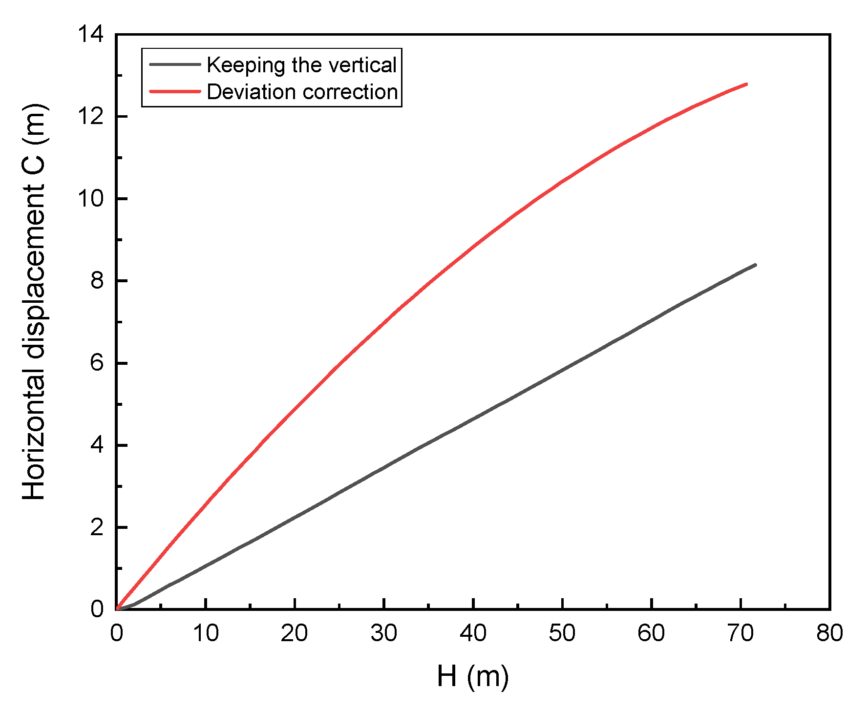
5.3. Comparison of Two Working Conditions

The horizontal displacement represents the horizontal projection distance between a point in the trajectory and the coordinate origin. It can indicate how far the trajectory deviates from the target. The calculation formula of horizontal displacement is as follows.
C i = E i 2 + N i 2
wherein, C i   —Horizontal displacement of a point (m), E i E coordinate value of a point (m), N i N coordinate value of a point (m).
Figure 16 shows the relationship between vertical depth and horizontal displacement under two working conditions. It can be seen from the figure that no matter what working conditions MVDS is in, it is unable to achieve the correction of downhole horizontal displacement. Furthermore, the horizontal displacement is accumulated with the increase of drilling depth. Due to the gradual decrease of deviation angle under the working condition of deviation correction, the growth rate of horizontal displacement is gradually increasing. By comparison, the growth rate of horizontal displacement is constant under the working condition of keeping the vertical, and that is because the variation range of deviation angle is very small during the process. In addition, because the deviation angle under the condition of deviation correction is larger than that under the condition of keeping the vertical, the horizontal displacement of the former condition is always greater than that of the latter. At the same time, it can be inferred from the above analysis that when the deviation control accuracy of MVDS is lower, it is possible to deviate from the downhole objective and miss the target because the horizontal displacement is too large. Therefore, it is necessary to optimize the relevant structure of the stable platform to improve its deviation control accuracy and enable it to be widely put into commercial application in the future.

6. Conclusions and Suggestion

This paper establishes the simulation method for deviation correction trajectory of mechanical vertical drilling system, and uses it to simulate and analyze the trajectory under two typical working conditions. The conclusions and suggestions are as follows:
  • The simulation method comprehensively considers the effects of tools, formation, BHA, and drilling process parameters. It can realize the simulation of deviation correction trajectory of the MVDS.
  • Only when the initial deviation angle is greater than the critical deviation angle can the eccentric block of MVDS sense the deviation and stop at the critical deflection angle position when the rig is started. From then, the tool can start to correct the deviation.
  • The existence of critical deflection angle makes MVDS correct deviation and change borehole azimuth at the same time. The borehole trajectory formed by drilling is a three-dimensional curve, which has the tendency of drifting to the left.
  • In the working condition of deviation correction, MVDS can effectively reduce deviation and gradually reduce azimuth. In the process of deviation correction, the deviation change rate decreases with the increase of vertical depth, and the azimuth change rate increases with the increase of vertical depth. Under the working condition of keeping the vertical, the MVDS is in the circulation process of deviation correction and natural deflecting. The deviation angle is always controlled at about the critical deviation angle, and the azimuth angle decreases intermittently. In the process of deviation correction and natural deflecting, the change range of deviation change rate and azimuth change rate is very small, and the relation curves of those with vertical depth are approximately horizontal straight lines.
  • MVDS cannot correct the horizontal displacement of the downhole. The deviation control accuracy of the current tool is lower, which easily leads to missing the target. It is necessary to optimize the structure of the stable platform to improve the deviation control accuracy (the critical deviation angle). For example, the length, radius, and density of the eccentric block should be increased as much as possible and the diameter and friction coefficient of the plate valves should be reduced to the best of one’s ability. At present, the trajectory of MVDS is a three-dimensional curve with a large dogleg angle, which increases the friction resistance of drill string and the possibility of downhole accidents. The force increasing measures can be used to compensate the error of the stable platform (the critical deflection angle) and make the critical deflection angle tend to 0° in the process of drilling, so that the trajectory of MVDS can be located in the vertical plane as far as possible with the aim of reducing the dogleg severity of the borehole.
Based on the above, the trajectory simulation method and analysis results are anticipated to not only provide a deeper understanding around the theoretical foundation of the MVDS, but to also provide guidance for the subsequent structure optimization.

Author Contributions

Methodology, software, writing—original draft, L.C.; Validation, writing—review & editing, project administration, K.Z.; Software, D.Y.; Supervision, B.L.; Resources, D.Z. All authors have read and agreed to the published version of the manuscript.

Funding

This work was supported by the National Key R&D Program of China (Grant No. 2018YFC0603405) and the National Natural Science Foundation of China (Grant No. 41802197).

Data Availability Statement

Data sharing not applicable.

Conflicts of Interest

The authors declare that there are no conflict of interest regarding the publication of this paper.

Nomenclature

F E Equivalent pushing force (N)
T P Pushing time of steering rib in a cycle (s)
θ A Opening angle of arc hole (Rad)
ω BHA angular velocity (Rad/s)
F P Reaction force of steering rib pushing against wellbore (N)
β Tool face angle of MVDS (Rad)
θ C Critical deflection angle of eccentric block (Rad)
r 1 , r 2 Inner and outer radius of eccentric block (mm)
α 1 , α 2 Angle between both sides of the eccentric block and X-axis (Rad)
F G Gravity of eccentric block (N)
ρ Density of eccentric block (kg/mm3)
v Volume of eccentric block (mm3)
g Acceleration of gravity (m/s2)
l Length of eccentric block (mm)
T E Eccentric moment of eccentric block (N·m)
α Inclination angle (Rad)
θ The deflection angle of the eccentric block relative to the lower side of the borehole (Rad)
T p Friction torque between plate valves (N·m)
r P Outer diameter of plate valve (mm)
μ P Friction coefficient between plate valves
P Pressure between plate valves (MPa)
J Moment of inertia of eccentric block (kg·m2)
ω 1 Initial angular velocity of the eccentric block (Rad/s)
ω 2 Terminal angular velocity of the eccentric block (Rad/s)
W F Friction work of plate valve (J)
W G Work of gravity (J)
α C Critical deviation angle (Rad)
P α Bit side force of deviation plane (N)
P φ Bit side force of azimuth plane (N)
M 0 Bending moment at bit (N·m)
M i Internal bending moment at each centralizer and variable cross section (N·m)
q i Horizontal uniform load of per drill string span (N/m)
L 0 Distance from steering rib to bit in first span drill string (m)
L 1 Distance from first stabilizer to steering rib in first span drill string (m)
L 2 The length of the second span drill string, i.e., the length of flex sub (m)
L 3 The length of the third span drill string, i.e., the distance from the upper part of the flex joint to the second stabilizer (m)
L 4 The length of the fourth span drill string, i.e., the distance between the second stabilizer and the upper tangent point (m)
Q Static pushing force, here is equivalent pushing force FE (N)
Q α Pushing force of deviation plane (N)
Q φ Pushing force of azimuth plane (N)
u i Stability factor of drill string
X ( u i ) , Y ( u i ) , Z ( u i ) Magnification factor of drill string
k Calculation factor (m−1)
E i Elastic modulus of drill string (Pa)
I i Moment of inertia of drill string (m4)
K α Deviation plane borehole curvature (°/m)
e 1 , e 2 Half of the difference between the outer diameter of the first and the second stabilizer and the borehole diameter (m)
e s Deflection at variable cross section (m)
y 0 ,   y 1 ,   y 2 ,   y 3 ,   y 4 The longitudinal coordinates of the drill bit, the center of the first stabilizer, the variable cross section, the center of the second stabilizer and the upper tangent point (m)
P 0 Weight on bit (N)
P i Axial force at midpoint of each drill string (N)
θ α Rotation angle at the deviation plane (Rad)
θ φ Rotation angle at the azimuth plane (Rad)
I b ,   I r 1 ,   I r 2 Bit anisotropy index and formation anisotropy index
[ E ] Identity matrix
γ Dip angle of stratum (°)
φ f Azimuth of stratum strike (°)
[ U ] , [ V ] , [ W ] All of them are real symmetric matrices, in which and [U] and [W] are related to well deviation angle α, deviation azimuth φ, dip angle of stratum γ and Azimuth of stratum strike φf, [V] is related to bit rotation angle θα and θφ
F x Deviation force (N)
F y Azimuth force (N)
F z Axial force (N)
A α Deviation trend angle (Rad)
A φ Azimuth trend angle (Rad)
K α Deviation change rate (Rad/m)
K φ Azimuth change rate (Rad/m)
Δ L Length of well section (m)
Δ N The displacement of bit in the north direction in a well section (m)
Δ E The displacement of bit in the east direction in a well section (m)
Δ H The displacement of bit in the vertical direction in a well section (m)
Δ S The horizontal projection length of wellbore trajectory in a well section (m)
D b Diameter of bit (mm)
D m Diameter of MVDS (mm)
D f Diameter of flex joint (mm)
D c Diameter of collar (mm)
C i Horizontal displacement of a point (m)
E i E coordinate value of a point (m)
N i N coordinate value of a point (m)

References

  1. Bram, K.; Draxler, J.; Hirschmann, G.; Zoth, G.; Hiron, S.; Kühr, M. The KTB Borehole—Germany’s Superdeep Telescope into the Earth’s Crust. Oilfield Rev. 1988, 7, 4–22. [Google Scholar]
  2. Chur, C.; Oppelt, J. Vertical Drilling Technology: A Milestone in Directional Drilling. In Proceedings of the SPE/IADC Drilling Conference; Society of Petroleum Engineers: Houston, TX, USA, 1993. [Google Scholar]
  3. Claus, C.; Thomas, B.; Bernhard, E.; Axel, S.; Trach, T.V.; Lothar, W. KTB-4 Years Experience at the Limits of Drilling Technology. In Proceedings of the SPE/IADC Drilling Conference; Society of Petroleum Engineers: Houston, TX, USA, 1995. [Google Scholar]
  4. Oppelt, J.; Chur, C.; Feld, D.; Juergens, R. New Concepts for Vertical Drilling of Boreholes. In Proceedings of the SPE/IADC Drilling Conference, Amsterdam, The Netherlands, 11–14 March 1991. [Google Scholar]
  5. Ma, T.; Chen, P.; Zhao, J. Overview on Vertical and Directional Drilling Technologies for the Exploration and Exploitation of Deep Petroleum Resources. Geomech. Geophys. Geo-Energy Geo-Resour. 2016, 2, 365–395. [Google Scholar] [CrossRef] [Green Version]
  6. Lin, C.; Zhang, K.; Liu, B.-L. Classification and Development Status of Automatic Vertical Drilling Tools. China Pet. Mach. 2020, 48, 1–11. [Google Scholar]
  7. Reich, M.; Oesterberg, M.; Montes, H.; Treviranus, J. Straight down to Success: Performance Review of a Vertical Drilling System. In Proceedings of the SPE Annual Technical Conference and Exhibition; Society of Petroleum Engineers: Houston, TX, USA, 2003. [Google Scholar]
  8. Chai, L.; Zhang, K.; Zhang, Y. Performance Test of the Pushing Actuator of the Small Diameter Vertical Drilling Tool. Explor. Eng. (Rock Soil Drill. Tunn.) 2020, 47, 87–93. [Google Scholar]
  9. Comeaux, B.; Gibb, J.; Kirkhope, K.; Shaw, P. New Automatic Vertical Drilling System For High Temperature, Harsh Environment and Performance Drilling Applications. In Proceedings of the Offshore Mediterranean Conference and Exhibition, Ravenna, Italy, 28–30 March 2007. [Google Scholar]
  10. Jones, S.; Feddema, C.; Castro, J.; Sugiura, J. Fully Mechanical Vertical Drilling System Delivers RSS Performance in Vertical Drilling Applications While Providing an Economical Alternative to Conventional Rotary Steerable Systems Set-Up for Vertical Hold Mode. In Proceedings of the IADC/SPE Drilling Conference and Exhibition; Society of Petroleum Engineers: Houston, TX, USA, 2016. [Google Scholar]
  11. Han, L.; Ni, H.; Zhao, J.; Liu, Z.; Wu, Z. Development of Mechanical Tool for Automatic Vertical Drilling. Acta Pet. Sin. 2008, 29, 766–768. [Google Scholar]
  12. Wang, J.; Xue, Q.; Liu, B.; Li, L.; Li, F.; Zhang, K.; Zang, Y. Experimental Measurement on Friction Performance of PDC Bearings for Oil Drilling under Different Working Conditions. Measurement 2020, 163, 107988. [Google Scholar] [CrossRef]
  13. Li, L.; Xue, Q.; Liu, B.; Wang, J.; Li, X. The Dynamics of Eccentric Block in a Fully Mechanical Vertical Drilling Tool under the Effect of Torsional Vibration. Adv. Mech. Eng. 2018, 10, 1687814018770497. [Google Scholar] [CrossRef] [Green Version]
  14. Zhang, Y. Design and Simulation Test of a Pushing Unit of Push-the-Bit Vertical Drilling System. Master’s Thesis, China University of Geosciences, Beijing, China, 2020. [Google Scholar]
  15. Wang, R.; Xue, Q.; Han, L.; Sun, F.; Yue, W. Torsional Vibration Analysis of Push-the-Bit Rotary Steerable Drilling System. Meccanica 2014, 49, 1601–1615. [Google Scholar] [CrossRef]
  16. Xue, Q.; Leung, H.; Huang, L.; Zhang, R.; Liu, B.; Wang, J.; Li, L. Modeling of Torsional Oscillation of Drillstring Dynamics. Nonlinear Dyn. 2019, 96, 267–283. [Google Scholar] [CrossRef]
  17. Liu, Z.; Samuel, R. Halliburton; Drilling; Engn Wellbore-Trajectory Control by Use of Minimum Well-Profile-Energy Criterion for Drilling Automation. SPE J. 2016, 21, 449–458. [Google Scholar] [CrossRef]
  18. Hadavand, Z. Reduction of Wellbore Positional Uncertainty During Directional Drilling. Master’s Thesis, University of Calgary, Calgary, AB, Canada, 2015. [Google Scholar]
  19. Elrayah, A. Deviation Control Mechanism Correlated Advanced 3D Automated Steering Techniques; LAMBERT Academic Publishing: Saarbruecken, Germany, 2012. [Google Scholar]
  20. Çağlayan, B.K. Torque and Drag Applications for Deviated and Horizontal wells: A Case Study. Master’s Thesis, Middle East Technical University, Ankara, Turkey, 2014. [Google Scholar]
  21. Li, L. Research on Dynamics and Optimization Method of Mechanical Stable Platform in Automatic Vertical Drilling Tools. Ph.D. Thesis, China University of Geosciences, Beijing, China, 2018. [Google Scholar]
  22. Wang, J.; Hu, Y.; Liu, Z.; Li, L.; Liu, B.; Huang, L. Dynamic Characteristics and Key Parameter Optimization of Mechanical Automatic Vertical Drilling Tools. Shock. Vib. 2021, 2021, 1–17. [Google Scholar]
  23. Bai, J. Bottom Hole Assembly Problems Solved by Beam-Column Theory. In Proceedings of the International Petroleum Exhibition and Technical Symposium; Society of Petroleum Engineers: Houston, TX, USA, 1982. [Google Scholar]
  24. Bai, J.; Huang, H.; Liu, Y. Three-Dimensional Analysis of Bottom Hole Assembly by Beam-Column Theory. Acta Pet. Sin. 1989, 10, 60–66. [Google Scholar]
  25. Liu, Y.; Gao, D. A Nonlinear Dynamic Model for Characterizing Downhole Motions of Drill-String in a Deviated Well. J. Nat. Gas Sci. Eng. 2017, 38, 466–474. [Google Scholar] [CrossRef]
  26. Yang, C.X.; Han, L.J.; Bu, Y.; Zhao, J. 2-D Model of BHA Mechanical Analysis for Automatic Vertical Drilling. Oil Drill. Prod. Technol. 2010, 32, 26–30. [Google Scholar]
  27. Gao, D.; Liu, X.; Huang, R. Three Dimensional Macro Analysis of Rock Bit Interaction. J. Univ. Pet. China Ed. Nat. Sci. 1989, 13, 23–31. [Google Scholar]
  28. Ho, H.S. Prediction of Drilling Trajectory in Directional Wells via a New Rock-Bit Interaction Model. In Proceedings of the SPE Annual Technical Conference and Exhibition; Society of Petroleum Engineers: Houston, TX, USA, 1987. [Google Scholar]
  29. Liu, Y.; Fu, J.; Liu, M.; Wu, H. Trajectory Prediction of Reentry Horizontal Well Based on Bit-Rock Interaction. Drill. Prod. Technol. 2006, 29, 9. [Google Scholar]
  30. Liu, X.; Qu, T.; Sun, Z.; Liu, K. Design of 3-D Drift Well-Path. Acta Pet. Sin. 1995, 16, 118–124. [Google Scholar]
Figure 1. Structure of automatic vertical drilling system.
Machines 09 00161 g001
Figure 2. Working principle of MVDS.
Machines 09 00161 g002
Figure 3. Critical deflection angle of eccentric block.
Machines 09 00161 g003
Figure 4. Simplified method of equivalent pushing force.
Machines 09 00161 g004
Figure 5. Structure and force diagram of eccentric block: (a) cross section of the eccentric block; (b) decomposition of gravity.
Machines 09 00161 g005
Figure 6. Circular coordinate system.
Machines 09 00161 g006
Figure 7. Movement diagram of eccentric block.
Machines 09 00161 g007
Figure 8. Mechanical model of BHA.
Machines 09 00161 g008
Figure 9. Schematic diagram of effective drilling force of bit.
Machines 09 00161 g009
Figure 10. Geometric model of natural parameter method.
Machines 09 00161 g010
Figure 11. Flow chart of deviation correction trajectory simulation method.
Machines 09 00161 g011
Figure 12. Deviation correction trajectory of MVDS: (a) three dimensional graph; (b) vertical section; (c) horizontal projection.
Machines 09 00161 g012
Figure 13. Data chart of deviation correction trajectory: (a) deviation and azimuth; (b) deviation and azimuth change rate.
Machines 09 00161 g013
Figure 14. Keeping the vertical trajectory of MVDS: (a) three dimensional graph; (b) vertical section; (c) horizontal projection.
Machines 09 00161 g014
Figure 15. Data chart of keeping the vertical trajectory: (a) deviation and azimuth; (b) deviation and azimuth change rate.
Machines 09 00161 g015
Figure 16. Horizontal displacement under two working conditions.
Machines 09 00161 g016
Table 1. Comparison of simulated and measured values.
Parameters of Drilling Process, Bit and FormationWell Depth/m Measured α Simulation α Error/° Measured φ Simulation φ / ° Error/°
F E = 20 kN
P 0 = 80 kN
β = 345°
I b = 0.75
I r 1 = 1
I r 2 = 1
1806.522.3221.85−0.47221.60222.32+0.72
1817.224.5124.62+0.11220.70221.82+1.12
1827.626.2227.26+1.04219.90219.80−0.10
1838.528.3528.86+0.51219.10218.82−0.28
1847.929.9229.76−0.16218.10217.63−0.47
1858.632.0633.22+1.16216.90217.26+0.36
Average error0.58 0.51
Table 2. Related parameters.
Structural Parameters of Stable PlatformDrilling Process ParametersCharacteristic Parameters of Formation and BitStructural Parameters of BHA
l = 1000 mm
r 2 = 40 mm
ρ = 7.8 × 10 6 kg/mm3
μ P = 0.08
P = 1 MPa
r P = 12 mm
P 0 = 50,000 N
F E = 10,000 N
I b = 0.75
I r 1 = 0.95
I r 2 = 0.95
γ = 30°
φ f = 270°
L 0 = 0.5 m
L 1 = 5 m
L 2 = 2 m
D b = 152 mm
D f = 100 mm
L 3 = 9 m
e 1 = 1 mm
e 2 = 1 mm
D m = 126 mm
D c = 120 mm
Publisher’s Note: MDPI stays neutral with regard to jurisdictional claims in published maps and institutional affiliations.

