1. Introduction
Modern medicine requires diagnostic imaging and preventive medicine. Most imaging medicine uses X-ray, MRI, CT, ultrasound, microscope, and cameras for precise diagnosis [
1]. The precision diagnosis camera enables the real-time observation of lesions [
2,
3,
4,
5]. The diagnostic camera adjusts the brightness of the LED to allow imaging in dark tissue [
6]. The disadvantage of the camera during the imaging process is the reflected light (specular reflection) from the lesion due to the light of the LED irradiated to the lesion. The light reflection generated by the LED interferes with the observation field of the lesion. In addition, the generation of light reflections prevents accurate diagnosis. Therefore, the emergence of light reflection makes it very difficult to observe the lesion [
7].
For tissue diagnosis, if light reflection is created due to the strong light intensity of the LED, the diagnostic field of view is blocked during the monitoring process of the camera. For example, when light reflection generates on the lesion for observation, the lesion cannot be seen, making it difficult to make an accurate diagnosis.
In order to suppress the occurrence of light reflection in the medical diagnosis field, there is a cumbersome need to change the orientation angle of the camera. In addition, the observer faces the cumbersome and complicated process of compensating for light reflection using separate software when shooting is completed. In these methods, it is difficult to expect a rapid diagnosis, and the color of the lesion may be lost in the course of the observer’s work. Then, the patient and the doctor in charge of diagnosis cannot expect accurate diagnosis results. To overcome this problem, several methods for light reflection suppression have been studied [
8]. However, research cases are still lacking, and the traditional trick method used in the field of medical diagnosis has been investigated. Most of the medical field has used a method of minimizing light reflection by adjusting the camera’s direction angle [
9].
To obtain the polarization effect of the camera, there is a method of irradiating the focal point of the LED in various directions and a method of controlling the beam focal length of the LED [
10]. However, it is not easy in the field to adjust the beam irradiation direction angle and focal length of the LED during the diagnosis process [
11]. In addition, the best imaging condition for light reflection suppression is to detect specular reflections generated in the spatial conversion process with RGB color functions for the brightness and color of the camera [
12]. The detected specular reflection removes the reflection region through deconvolution analysis in the wavelength band. The color image lost due to specular reflection removal restores the lost color through the use of a separate function [
12]. This reflected wave cancellation process requires a lot of data and calculation work, which requires complex mathematical operations [
12]. The method of collecting frames through continuous shooting requires that the reference image be trained in advance [
13]. In this method, the sum and difference are calculated by comparing the interval between the actual shooting frames and the reference training image interval. Then, the reflected light is removed by removing the image of the difference value [
13]. However, various cumbersome data collection processes for learning the reference image, lesion data, and normal tissue data follow [
14].
There is a method that involves using a polarizing filter in the camera and a method using a sensor that detects only the RGB values of the image by automatically detecting changes in the image [
15,
16,
17,
18]. However, the method of applying the polarizing filter reduces the shooting radius due to material loss of the filter and provides a dark image. Moreover, the RGB value detection method does not take into account the expected image loss and distortion due to material loss in the filter [
15,
16,
17,
18].
Research is needed to overcome the complex process of data collection and mathematical operation to suppress the light reflection of photographed data. This study is judged to be usefully applied to the field of medical diagnosis. This paper proposes a method for removing light reflection of an imaging camera. In order to remove light reflection, the filter controls vertical and horizontal polarizations through rotation with 90°, which induces the 90° difference from each other. At this time, the filter used is the linear polarized filter.
Section 1 introduces the motivation for this study.
Section 2 and
Section 3 present the research methods and results, and
Section 4 a discussion. Lastly,
Section 5 concludes the article.
2. Analysis for Removal of Specular Reflection
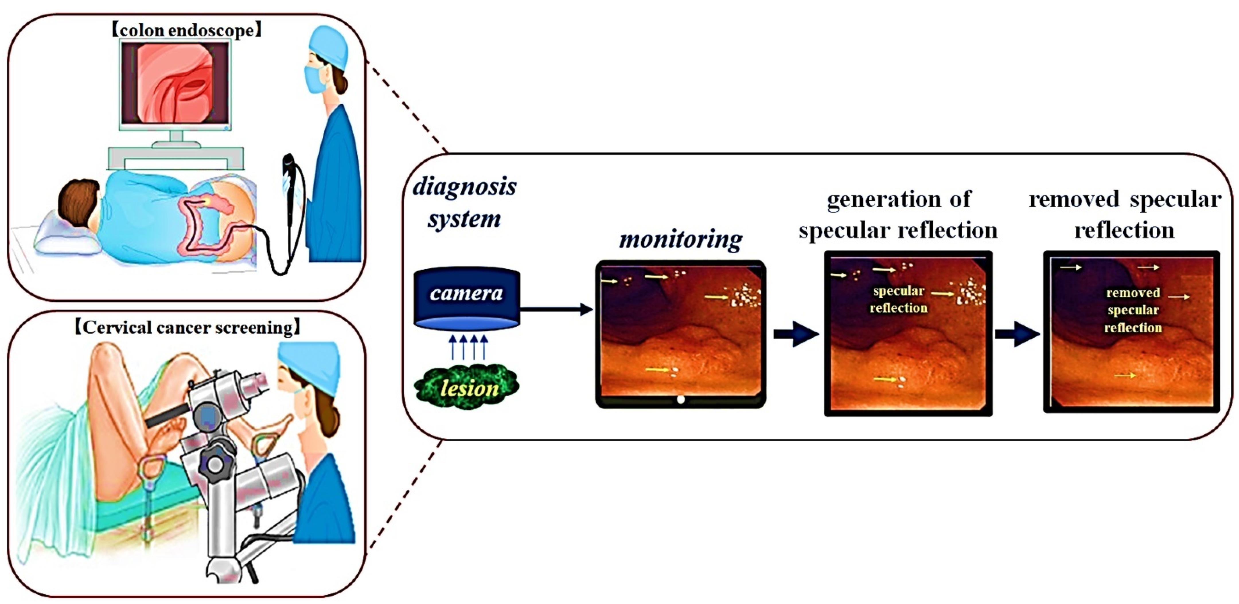
In the diagnostic endoscopy procedure, a camera is inserted into the organ as shown in
Figure 1, and the endoscope camera confirms the lesion status of the mucosa. When photographing a dark organ from a picture, the camera surroundings irradiate the LED on the tissue to capture a bright image.
The large problem in the endoscopic camera imaging process is the emergence of light reflection, as shown in
Figure 2 [
7]. The occurrence of light reflection obstructs the observation field of the lesion, making it difficult for an observer to make an accurate diagnosis. This light reflection controls the polarization direction of the filter by analyzing the characteristics of polarization and Malus’ law [
19,
20,
21]. In consequence, the light reflection can be eliminated.
To remove light reflection, two filters (
E1,
E2) are configured, as shown in
Figure 3. In
Figure 3,
E1 and
E2 are the first and second polarization filters, and the
E and H are the electric and magnetic fields of polarization. LPL is linear polarization.
p1,
p2, and
p3 are the positions where the image and light pass through the filter, and
Es is the sum of
Ez and
Hz (
Es =
EzHz). In this case,
Ez is vertical polarization and
Hz is related to horizontal polarization. Consequently, the image and light are mixed together.
Eo is a mixture of image and light with the same horizontal polarization as
E and
H.
Ep means an image from which the
Ex,y component (light reflection) is removed and the light reflection in which only the
Hy component remains.
In the figure, the light (
Escosθs) of
p1 incident on the camera through the imaging of the lesion has vertical polarization (
Ey) and horizontal polarization (
Ez) proceeding in the
x,
y, and
z directions as shown in Equations (1) and (3) (
Ey = 1,
Hx = 1) is assumed [
20,
21]. In the formula,
Ez(y, x) means
Ez of magnitude in the
y and
x directions.
θ denotes the filter rotation direction angles of
E1 and
E2. In the
z-direction light (
p2) passing through the polarization filter of
E1,
Eo, and
Es are changed to horizontal polarization (
Ey = 0,
Hx = 0), which is the sum of
Eo and
Es, resulting in
Eo =
Es = 0 [
20,
21].
The
z-direction light (
p3) passing through the filter of
E2 only passes through
E0 in the horizontally polarized state. Then,
Eo becomes
E0 ≠
Es, and
Eo becomes
Eo = 0. Since the phase of
Eo may differ by 0 or an integer multiple of 2π,
E0 proceeds in the
x-direction as in Equations (4) and (5). All of the polarized waves of
Eo moving in the
x-direction are changed to horizontal polarization (
Eo = 0), and the image is changed to a state in which light reflection is removed [
21]. Finally, concerning
E0 (
p2), as in Equation (6), vertical polarization and horizontal polarization differ by π in the
z direction. Eventually, only the horizontal polarization corresponding to π/2 passes through the polarization filter of
E2, resulting in reduced light reflection. An image (
Ep of
p3) is provided [
21].
where
p1 is polarized in the vector plane of
x,
y, and
z, and has vertical and horizontal vibration directions (
x,
y) at a direction angle (
θ) of 0°. The polarized waves
p1 of
Ey and
Hy passing through the first polarization filter
E1 oscillate
p2 in the vertical direction
y. When the direction angle
θ of the second polarizing filter
E2 is 90°, only the
Ey component passes through the vertical polarized wave of
p2 passing via the second polarizing filter
E2, and the
Hx intensity is weakened. The propagation angle of the polarization with respect to
Ep can be analyzed using the ABCD matrix shown in Equation (7) and
Figure 4 and
Figure 5 to reduce the light intensity according to the change in
θ [
21]. If the intensity of light
E(x, y) with respect to polarization rotates from
y to
z and
θ is
cos 90°, light reflection is reduced to the zero (0).
When
θ becomes Δ
Φi (Δ
Φi│i = Φz − Φx = 0, π/2, π/4, 3π/4, π), the light intensity (
Eo(x, y)) changes, as shown in
Figure 6.
For example, when the light reflection intensity (
Iref) passes through two filters (
θEp = 90° difference) (
E1 = 0°,
E2 = 90°), the light reflection intensity (
Iref) at the
p3 position is reduced by more than half. Eventually, the intensity of light reflection (
Iref) is lowered by more than half compared to the intensity of light (
IEp). The reason for this is that, as in Malus’s law in Equation (8), when the rotation angle of the first filter (
θref = 0°) is fixed, when the second filter is rotated at 90° (
cosθEp = 90°), the intensity of light reflection (
Iref) becomes 0 [
19,
20,
21].
If the
IEp is 0 mW/cm
2, the rotation angle (
θref) of the
E1 filter is 0°, and the rotation angle (
θEp) of the
E2 filter is 90°, as in Equation (9), the light reflection intensity (
Iref) is interpreted again as 50 mW/cm
2, as given in by
Table 1, when
IEp is 0 mW/cm
2 (
θEp = 90°). At this time, when the rotation angle
θref of the
E1 filter is 0°, the rotation angle
θEp of the
E2 filter corresponds to 0° to 360°.
When analyzing Equations (1)–(9) and
Table 1, since the first polarizing filter (
E1) was fixed at 0°, the second polarizing filter (
E2) was sequentially rotated from 0° to 360°. Similarly, a phenomenon in which the intensity of light reflection decreases and rises is repeated like a sine wave. When the rotation angle
θEp of the
E2 filter is 90° or 270°, the intensity of light reflection becomes 0 mW/cm
2, and a phenomenon in which light reflection is removed arises. For this reason, as shown in
Figure 7, when the rotation angle (
θEp) is 0°, light (light reflection) passes through the second polarization filter (
E2), and the light reflection intensity (
Iref) has a maximum value. That is, the intensities for
IEp and
Iref are the same and they have an equilibrium relationship with each other. When the second polarizing filter
E2 rotates from 10° to 80° during the rotation process,
IEp and
Iref are out of horizontal relationship.
When the rotation axis of the second filter (E2) reaches 90°, IEP and Iref (the difference between E1 ≠ E2 = 90° of the filter) intersect with each other, so that IEP has the maximum value (IEp = 1) and Iref will have the minimum a value of (Iref = 0). Consequently, the intensity of light reflection is lost, and the image quality is increased. If the rotation angle of the filter deviates from 90° (<100°), IEP changes to the minimum value (IEP = 0) and Iref changes to the maximum value (Iref = 1). At this time, the IEP and Iref will have the same value (IEP = Iref). This phenomenon is repeated. To summarize, the method for maximally suppressing light reflection is that when the first filter E1 is 0°, the second filter E2 should be 90°. As a result, the polarized wave p3 that has passed through E2 outputs only the polarized wave Ep with reduced light reflection. As a result, the intensity of light loses its maximum value, and eventually, the intensity of light starts to decrease slowly, and when the rotation angle θEp is 90° (270°), the intensity of light reflection (Iref) becomes 0.
3. Experiment Composition and Results
In order to obtain the effect of reducing light reflection, the experimental device is configured as shown in
Figure 8. The device for the experiment consists of a camera, an LPL filter, and an LED. The method followed to obtain the result uses phantom. The first polarizer filter connected in front of the camera has a rotation angle (
θ) of 0° and the filter is fixed. However, the filter is in a polarization state. The second filter has a rotation angle (
θ) of 0° and this filter is unpolarized. The filter connected to the LED changes the rotation angle (
θ) from 0° to 360°, and the filter is rotated.
The filter for connection to the camera and LED was made using 3D printer technology to make a fixed frame, and the LED and filter are connected in this frame. The installation angle of the camera is 0° and the irradiation direction angle of the LED (the angle between the camera and the LED) is 30°. Moreover, the number of irradiated LEDs is 10. The working distance (WD) between the camera and the LED and the phantom is 14 cm.
The main parameters of the LED (010C3UC020, DAKWANG, Yantai, China), camera (Dr. Cervicam C20, NTL Healthcare, Seongnam, Republic of Korea), and filter used for the experiment are presented in
Table 2.
For the use of a linear polarized filter (Schneider-Kreuznach, Schneider (1.25 inch), I55543, Bad Kreuznach, Germany), the wavelength band is 420–750 nm and the diameter of the lens is 27 mm. In addition, the thickness of the filter lens is 0.25 mm, and the transmittance is 34%. Extinction ratio is >10.000:1 and the LPL filter is uncoated.
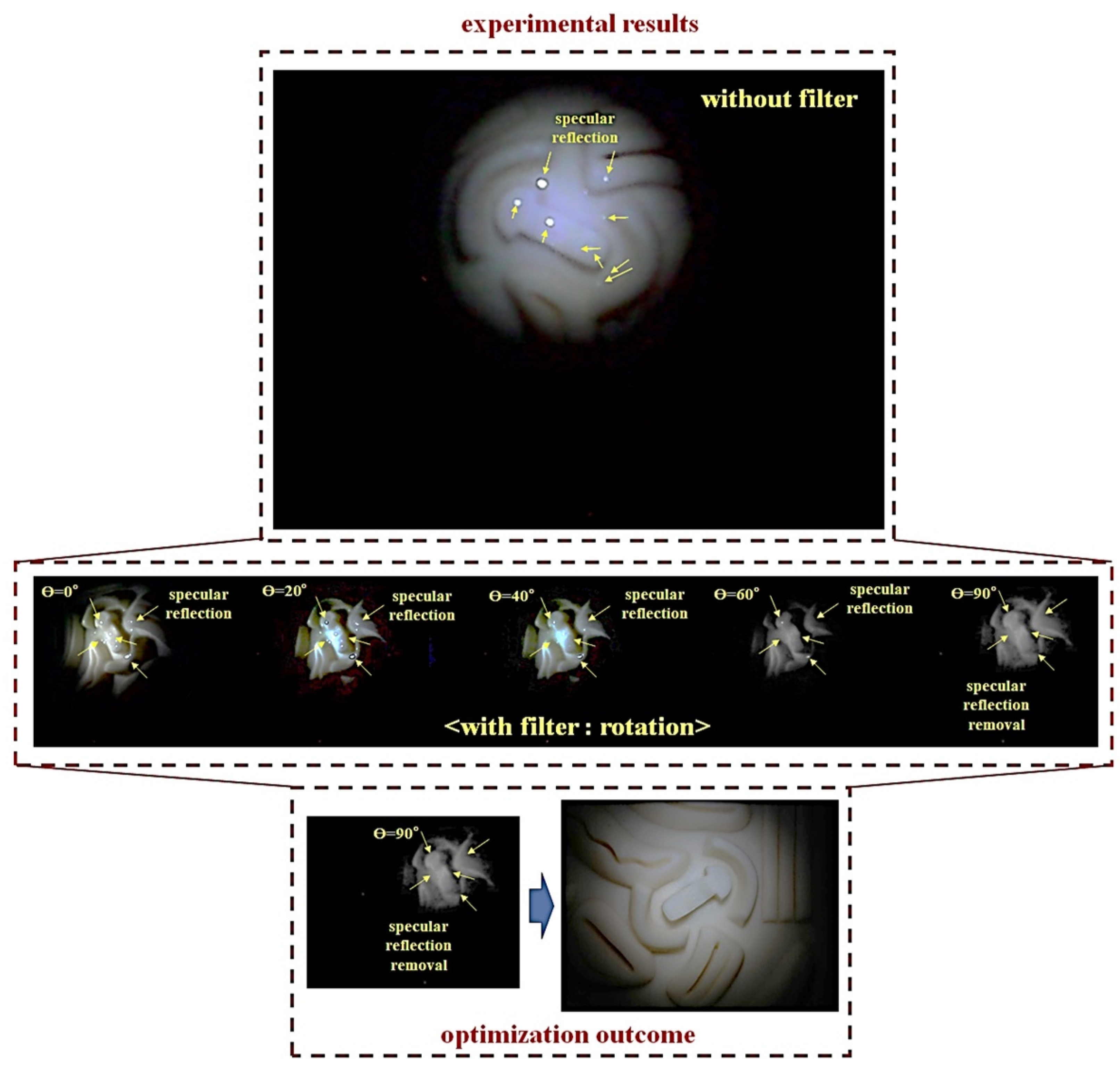
The experimental results using phantom are shown in
Figure 9. From the figure, specific reflection is generated on the phantom. The arising position of the specific reflection is indicated by a yellow arrow. As a result of using the filter, when the rotation angle (
θ) of the filter connected to the LED is 0°–360°, it can be observed that light reflection is reduced, and the rotation angle (
θ) is 90°. When it is analyzed, that light reflection is reduced.
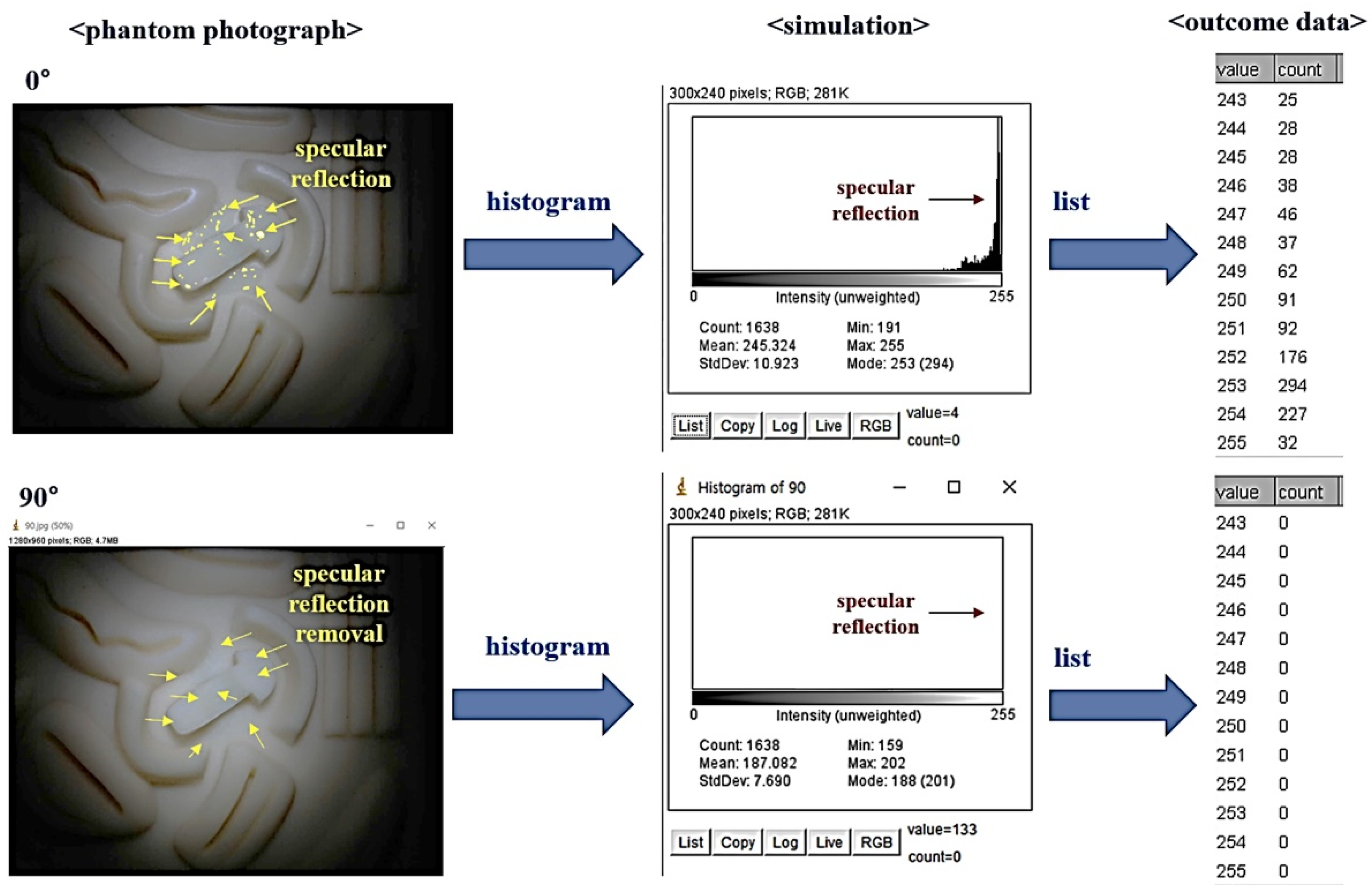
The captured image results were simulated using an ROI (region of interesting) program (PyCharm. JetBrains, Prague, Czech Republic), as shown in
Figure 10. In the simulation result, when the rotation angle
θ of the filter is 0°, the light reflection generation position is indicated by a yellow point. In this case, the intensity (intensity of light) corresponds to 0 in the area where light reflection does not occur in the histogram. However, since most of the light reflection is generated to the phantom, the light reflection intensity is no longer 0. Therefore, the intensity of light reflection has a value of 25–294, and the maximum intensity of light reflection is 294. However, when the rotation angle (
θ) of the filter was 90°, the intensity of light reflection changed to 0.
Figure 11 shows the human tissue test results for the phantom imaging results in
Figure 9 for the reliability performance test. For the reliability of the study, this experiment was conducted three times. In order to increase the reliability of the research methodology, direct pictures were taken using my own oral cavity instead of a phantom. In the experimental results, light reflection happens when the LPL filter was not applied, but when the rotation angle (
θ) of the filter is adjusted from 0° to 360° using the LPL filter, when the rotation angle was 90°, the light reflection was sufficient and could be removed.
In
Figure 11, when the LPL filter was used, the phantom, uvula, lingual frenulum, and palatine raphe had light reflections like yellow markers. When the LPL filter (first) is used, the phantom, uvula, lingual frenulum, and palatine raphe, like yellow markers, have light reflections removed so that the image looks clear. When the reproduction test (second and third) was performed to obtain a reliable image to obtain the effect of removing light reflection when the LPL filter is used, the image result of the first LPL filter was similar.
4. Discussion
This study proposes a method to efficiently reduce the light reflection of images generated by diagnostic systems, such as microscopes, endoscopes, and cameras.
The mention of the genesis of light reflexes in all tissues is cautious. However, soft fibrous tissues, such as the stomach, colon, and cervix, for endoscopic diagnosis are confirmed in the clinical field as light reflection generates. When the LED is irradiated to the tissue mucosa, light reflection rises according to Snell’s law. Ambient reflection, diffusive reflection, and specular reflection are highly likely to occur because of the difference between the density of the cavity, the tissue density, and the moisture density of the tissue as the cause of light reflection [
22].
In the light of the LED irradiated from the cavity, both the absorbed light and the reflected light are generated at the same time because of the density at the water surface interface or the tissue surface interface. The reflected light causes scattering, which prevents monitoring through camera shooting.
In the experimental process, the light reflection intensity is almost identical in the wavelength band of 400–1100 nm. Vertical polarization and horizontal polarization are generated together in the wavelength range. For that reason, it is important to eliminate all vertical polarizations. The wavelength band of 400–1100 nm is a white light source LED. During the endoscopic procedure, white light (LED) is used to brightly image the dark tissue space. Light reflections are severe in white illuminated LEDs (400–1100 nm). In order to reduce light reflection, it is inconvenient to adjust the orientation angle of the camera or adjust the brightness of the LED at the clinical diagnosis site [
9]. However, using these methods, it is not easy to obtain clear diagnostic results in the clinical diagnosis process. In particular, if the camera orientation angle is adjusted, the lesion shape observation angle may be changed. In addition, if the brightness of the LED is adjusted, it is observed with a dark background. Accordingly, it is time-consuming and cumbersome to correct the photographing result using an imaging process. For quick and accurate diagnosis, a clear image must be provided, and light reflection must be removed to secure the observation field of the lesion. Accordingly, it is judged that the evaluation of the method of removing light reflection of the camera will contribute a lot to the clinical diagnosis phenomenon.
In this study, a phantom (a silicone material for suturing practice) was used instead of an animal experiment to examine the effect of light reflection removal, and the tissue in
Figure 11 was taken using my oral cavity. Consequently, the experiment through oral imaging was repeated three times and the reliability of the results was increased. If a filter made of film material is used, it is judged that the proposed method can be sufficiently commercialized by applying it to a camera shooting system. Thereby, if excellent results are obtained through clinical trials, it is expected that the use value in the field of clinical diagnosis will increase.
5. Conclusions
This study proposes a method for removing light reflection in diagnostic imaging systems, such as microscopes, endoscopes, and cameras, and proves the possible results through experiments. The main method for the proposed study is to control the polarization using the rotation angle of the filter. Thus, by controlling the propagation directions of the vertical and horizontal polarizations, the light reflection for the vertical polarization is removed and only the horizontal polarization for the video image can pass through. A phantom was used to obtain the experimental results, and the photographic experiments were repeated three times through the oral tissue to prove the high reliability of results. In consequence, the oral imaging results were consistent with the phantom test results without any light reflection.
When an LPL filter was used, light reflection is generated to the phantom and tissue. However, when the LPL filter (first) was used, the image showed the light reflection removed from the phantom and tissue. Moreover, a reproduction test was conducted to obtain a reliable image, and the image result was similar to the image result of the first LPL filter.
The proposed method eliminates light reflection in real time at the diagnostic imaging site without additional imaging software correction processing, providing excellent imaging. Thus, it is possible to secure a field of view for observation of the lesion through clear imaging results and to obtain fast and accurate diagnosis results. In addition, the advantage of the proposed method can be connected to all cameras, microscopes, and endoscopes regardless of the size of the filter, so it can be applied to clinical diagnosis sites. So, the research method is highly practical. It is expected that this research method can be sufficiently applied to clinical diagnosis sites through product design and clinical trials in the future.


