Abstract
Purpose: The present study aims to describe a new 2D–3D fusion registration method in the case of endovascular redo aortic repair and compare the accuracy of the registration using the previously implanted devices vs. bones as landmarks. Materials and Methods: This single-center study prospectively analyzed all the patients that underwent elective endovascular re-interventions using the Redo Fusion technique between January 2016 and December 2021 at the Vascular Surgery Unit of the Fondazione Policlinico Universitario A. Gemelli (FPUG)—IRCCS in Rome, Italy. The fusion overlay was performed twice, first using bone landmarks (bone fusion) and the second using radiopaque markers of a previous endovascular device (redo fusion). The pre-operative 3D model was fused with live fluoroscopy to create a roadmap. Longitudinal distances between the inferior margin of the target vessel in live fluoroscopy and the inferior margin of the target vessel in bone fusion and redo fusion were measured. Results: This single-center study prospectively analyzed 20 patients. There were 15 men and five women, with a median age of 69.7 (IQR 42) years. The median distance between the inferior margin of the target vessel ostium in digital subtraction angiography and the inferior margin of the target vessel ostium in bone fusion and redo fusion was 5.35 mm and 1.35 mm, respectively (p ≤ 0.0001). Conclusions: The redo fusion technique is accurate and allows the optimization of X-ray working views, supporting the endovascular navigation and vessel catheterization in case of endovascular redo aortic repair.
1. Introduction
The use of endovascular techniques has increased over the last decade. The evolution of device technology has allowed physicians to perform more complex, minimally invasive aortic endovascular repairs. Imaging systems have also evolved to facilitate these challenging procedures [1]. The latest generation of hybrid operating rooms (HOR) is equipped with advanced imaging tools, such as fusion imaging (FI), associated with better procedural and short-term outcomes and potential clinical long-term benefits [2]. The use of image fusion guidance has been associated with several procedural benefits. Prior publications have reported a significant reduction in both operator and patient radiation exposure and contrast medium injection with the routine use of fusion guidance by trained operators applying the ‘as low as reasonably achievable’ (ALARA) principles [3,4].
Fusion imaging is a technique that allows three-dimensional (3D) visualization of intraoperative landmarks by projecting 3D images derived from the pre-operative computed tomography (CT) angiography (CTA) scan onto a two-dimensional (2D) intraoperative fluoroscopic image (2D–3D fusion imaging) [5]. Registration can be either 2D–3D, which is performed by superimposing the 3D bone model obtained from the CTA onto the bony structures on 2D fluoroscopic images (which requires two perpendicular 2D images), or 3D–3D by superimposing the CTA 3D bone model and aortic calcifications on to a 3D bone model obtained from an on-table cone-beam CT. However, performing a CBCT at the beginning of the procedure can at times be logistically challenging and is associated with significant radiation exposure [6].
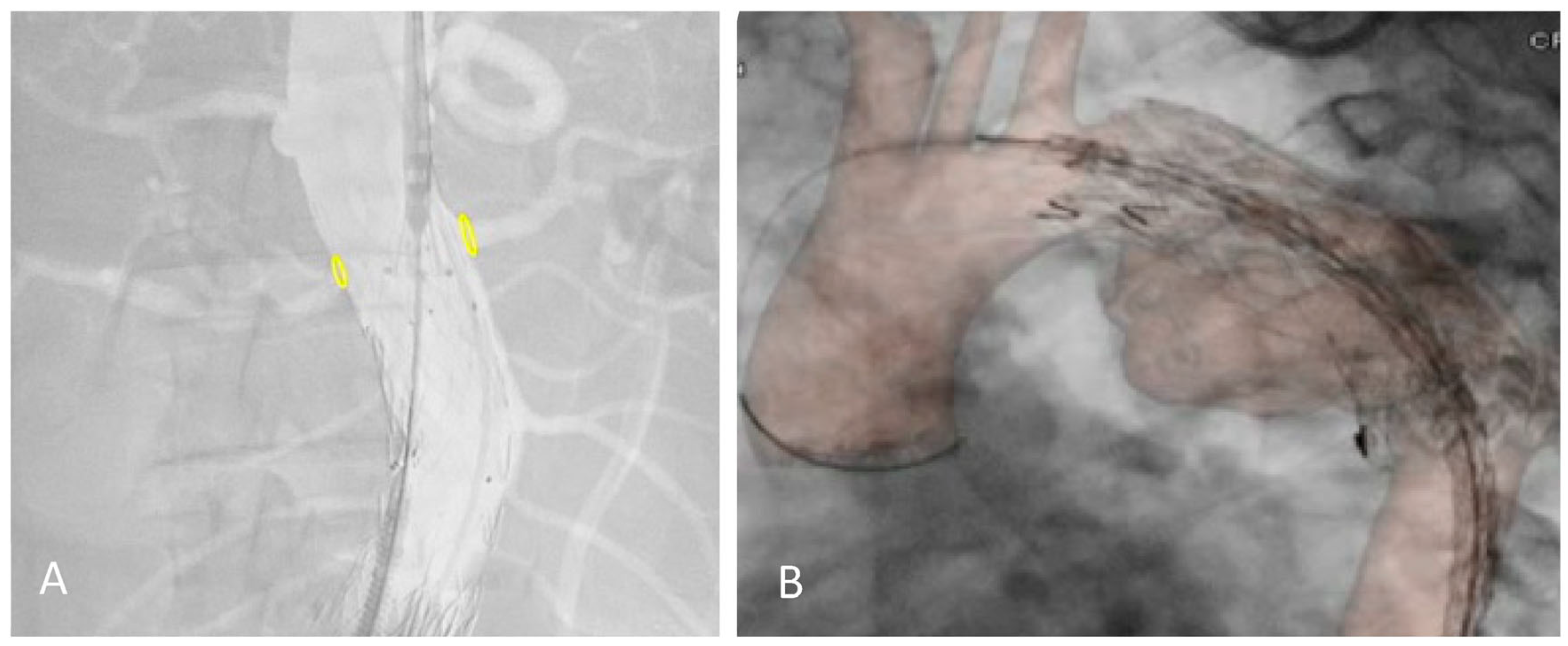
The 2D–3D FI technique relies on bones as anatomical landmarks. However, the pre-operative CTA is performed with the upper limbs in hyper-abduction, creating a potential mismatch with the intraoperative position of the patient (arms adducted with the elbows extended). A discrepancy between our fusion reconstruction and the real target vessels position can be observed, especially after stiff guide and shaft device insertion, and in the thorax overlay (Figure 1).
Figure 1.
Proximal relining for type IA endoleak in a previous EVAR (A) and TEVAR (B) under the redo fusion technique. Accuracy of the yellow markers on bilateral renal arteries after shaft device insertion and in the thoracic aorta.
Patients who undergo endovascular aortic repair remain at risk for re-intervention indefinitely. In the three years after endovascular aneurysm repair (EVAR), up to one-fifth of patients require a re-intervention procedure [7]. Re-interventions after EVAR, thoracic endovascular aneurysm repair (TEVAR) or complex fenestrated (F-) or branched (B-) EVAR are frequently treated with different endovascular strategies, which together comprise endovascular redo aortic repair. Redo aortic operations are technically demanding and are carried out with increased risks. Improving technology, such as fusion imaging, should mitigate some of this risk [8].
In case of patients with previous endovascular devices such as stents, vascular plugs, or endoprosthesis, it is possible to obtain a fusion image with the previously implanted devices as landmarks.
The present study aims to describe a new 2D–3D fusion registration method in the case of endovascular redo aortic repair and compare the accuracy of the registration using the previously implanted devices (redo fusion) vs. bones (bone fusion) as landmarks.
2. Materials and Methods
This single-center study prospectively analyzed all the patients that underwent elective endovascular re-interventions using the redo fusion technique between January 2016 and December 2021 at the Vascular Surgery Unit of the Fondazione Policlinico Universitario A. Gemelli (FPUG)—IRCCS in Rome, Italy.
Indications for re-interventions included: type I and II endoleaks; staged procedures for thoracic, thoraco-abdominal and complex abdominal aortic aneurysms; and chronic type B dissection treatment. Emergency procedures or procedures conducted without fusion imaging were excluded.
All of the procedures were performed in an HOR (Artis Zeego; Siemens Healthcare GmbH, Forchheim, Germany), under general anesthesia, by a single experienced operator. Imaging analysis and collection of measurement data were performed independently by two vascular surgeons experienced in aortic graft planning according to the standardized protocol. The two observers used the same standardized measurement technique, and each observer repeated all of the measurements two times for each patient.
Bone Fusion Technique
Before each procedure, bone and aortic 3D models were reconstructed from the preoperative CTA scan (performed within three months prior to the procedure) on a workstation (Leonardo, Healthcare Sector, Siemens AG, Forchheim, Germany) and sent to the X-ray system. The pre-operative CTA was processed by placing digital marks around the ostium of the target vessels on the CTA. It was then fused with live fluoroscopy. Registration of this 3D preoperative model was performed using bone landmarks visible on two fluoroscopic orthogonal shots (anterior–posterior and lateral) of the spine. During the procedure, this layout was used to center the region of interest, and to adjust collimation, without requiring fluoroscopy. The position of the target vessels was confirmed by a 6-cc contrast medium injection at 30 cc/s performed after the stiff wire insertion.
Redo Fusion Technique
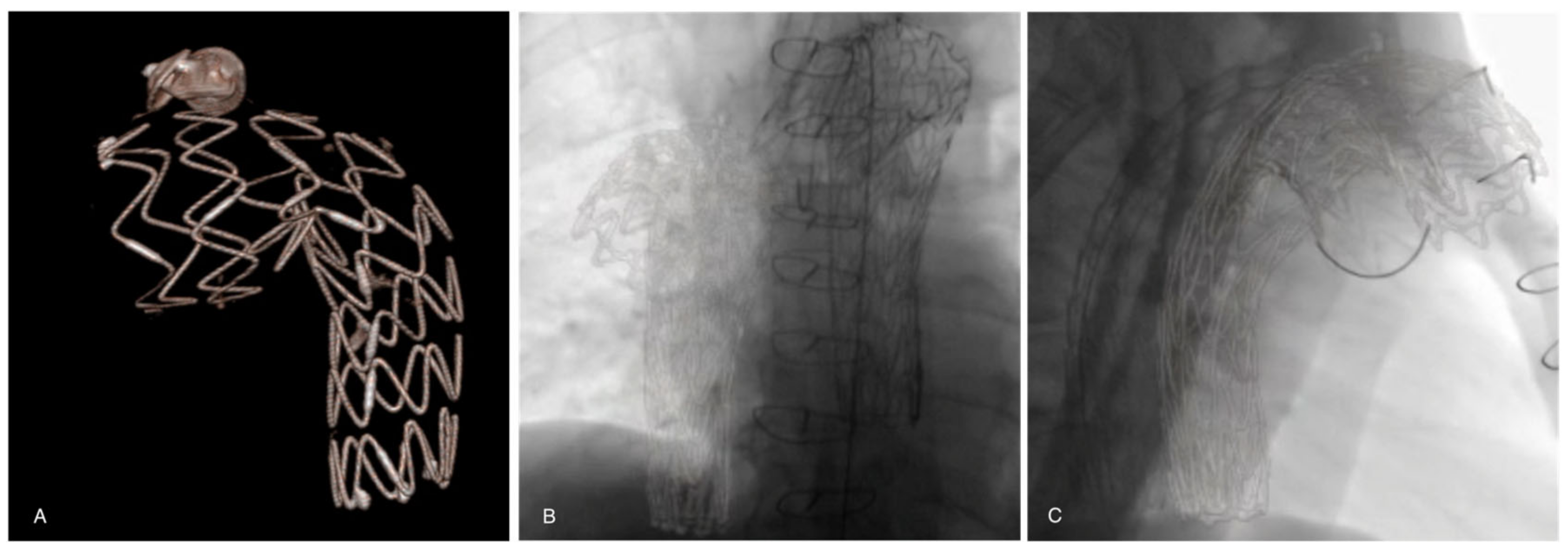
Before each procedure, aortic 3D models were reconstructed from the pre-operative CTA scan (performed within three months prior to the procedure) on a workstation (Leonardo, Healthcare Sector, Siemens AG, Forchheim, Germany) and sent to the X-ray system. The pre-operative CTA was processed by placing digital marks around the ostium of the target vessels on the CTA. It was then fused with live fluoroscopy. Registration of this 3D pre-operative model was performed using stent grafts, vascular plugs, coils, or other radiomarkers from a previous endovascular procedure visible on two fluoroscopic orthogonal shots (anterior–posterior and lateral) of the spine (Figure 2). During the procedure, this layout was used to center the region of interest, and to adjust collimation, without the need for fluoroscopy. The position of the target vessels was confirmed by a 6-cc contrast medium injection at 30 cc/s performed after the stiff wire insertion.
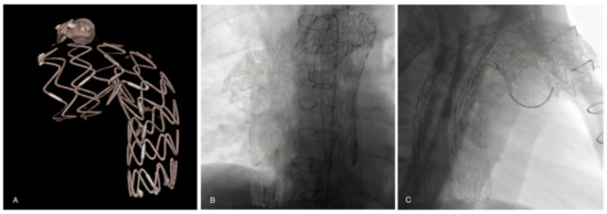
Figure 2.
(A) A previous thoracic stent-graft three-dimensional volume rendering model reconstructed from the preoperative CTA. Registration and overlay are performed with two fluoroscopic orthogonal antero-posterior (B) and lateral (C) shots.
Bone Fusion vs. Redo Fusion comparison
In the present study the overlay was performed twice: the first using bone landmarks (bone fusion), and the second using radiopaque markers of previous endovascular materials implanted in the aorta (redo fusion). Comparison of the accuracy of the alignment of the two techniques was performed by two operators with measurements taken twice for each technique.
All the definitions of the variables used are reported in Table 1. Longitudinal distances between the inferior margin of the ostium of the target vessel in live fluoroscopy and the inferior margin of the target vessel in bone fusion and redo fusion were measured. Intra-observer and interobserver variability, L1 and L2 distances, L1 and L2 measurements in two subgroups of patients with the predefined distance between fusion marker and target vessel (cut-off 3 cm), and L1 and L2 measurements in the two subgroups of patients with predefined aortic angle (cut-off 45°) were performed. Intra-observer variability was defined as the difference in repeated measurements by the same observer. Interobserver variability was defined as the difference in the measurements between the two observers.

Table 1.
List of the measurements obtained on the 3D workstation.
Statistical analysis
Continuous data are reported as the mean ± standard deviation (SD) or, in the case of Gaussian distribution, as the median with interquartile range (IQR). Two-group comparisons were performed with the paired t-test. The threshold for statistical significance was set at a p-value < 0.05. SPSS software (version 23; IBM Corporation, Armonk, NY, USA) was used for statistical analysis.
3. Results
This single-center study prospectively analyzed 20 patients who underwent elective endovascular re-interventions between January 2016 and April 2021 at the Vascular Surgery Unit of the FPUG in Rome, Italy. There were 15 men and five women, with a median age of 69.7 (IQR 42) years. Indications for re-interventions were type IA (n = 3) and II (n = 1) endoleaks, staged procedures for thoracic (n = 4), thoraco-abdominal (n = 7) and complex abdominal (n = 3) aortic aneurysms, and chronic type B dissection (n = 2) treatment. The patients’ details are reported in Table 2.

Table 2.
List of patients’ characteristics.
Table 3 shows the reproducibility of repeated distance measurements. The median difference of the intra-observer measurements was 0.85 mm and 0.81 mm for bone fusion and redo fusion, respectively (p = 0.2). The interobserver variation was 0.7 mm and 0.65 mm for bone fusion and redo fusion, respectively (p = 0.8).

Table 3.
Variation between intra-observer and interobserver measurement in L1 and L2.
The distance between the inferior margin of the target vessel ostium in DSA and the inferior margin of the target vessel ostium in bone fusion (L1) and redo fusion (L2) were 5.35 mm and 1.35 mm, respectively (p ≤ 0.0001) (Table 4).

Table 4.
Analysis of accuracy of measurement over 20 patients by paired t tests.
To confirm the accuracy of the redo fusion method, the measurements were performed on two subgroups of patients (Table 5). The criteria were established based on the distance between the fusion marker and the target vessel (> or ≤3 cm). The measurements were statistically significant for the first subgroup (>3 cm) of seven patients (p < 0.0008), with an average distance of 5.28 mm and 1.60 in group L1 and L2, respectively. The second subgroup (≤3 cm) of 13 patients had an average distance of 5.38 mm and 1.21 mm in the L1 and L2 group, respectively (p < 0.0001).

Table 5.
Analysis of accuracy of measurement over two patient subgroups.
Further measurements were performed on two other subgroups of patients, categorized based on an aortic angle of 45° at the level of new working area level (Table 6). The first subgroup of five patients (<45°) had an average distance of 4.40 mm and 1.40 mm in the L1 and L2 group, respectively (p < 0.01). The second subgroup of 15 patients (≥45°) had an average distance of 5.80 mm and 1.33 mm in the L1 and L2 group, respectively (p < 0.0001).

Table 6.
Analysis of accuracy of measurement over two patient subgroups.
4. Discussion
Over the decades, the development of endovascular aortic repair has revolutionized the treatment of different aortic pathologies. Endovascular repair has also gained widespread acceptance for thoraco-abdominal aortic diseases with F-BEVAR in a staged approach [9]. Endovascular repair is associated with lower peri-operative morbidity, mortality, and a shorter hospital stay when compared with open surgical repair. However, the primary tradeoff between endovascular and open surgery is the durability of the repair. Endovascular operations are associated with higher rates of re-intervention and late aneurysm rupture than open surgical repair [10]. A recent study from Columbo et al. on 12,911 patients reported a cumulative rate of re-intervention of 15% at three years and 33% at 10 years after EVAR [11]. The rates of re-intervention after TEVAR ranges from 10–15% for thoracic aortic aneurysms to 46% after complicated type B thoracic aortic dissections [12,13].
Risk factors for failure following aortic repair include larger abdominal aortic aneurysm in necks, severe neck angulation, as well as clinical variables [8]. Endovascular aortic repair is challenging, and redo aortic operations are technically demanding and are carried out with increased risks [8,14]. Most re-interventions are performed because of endoleak, stent migration, graft kinking with stenosis or occlusion, and proximal or distal disease progression [15]. Previous studies on aortic neck enlargement after endovascular repair of thoracic and infrarenal aortic aneurysms have found enlargement after endograft repair that could lead to device migration, endoleak, and rupture [16,17,18]. Moreover, many failed endovascular repairs could have been avoided if meticulous and accurate planning (with the significant contribution of pre-operative planning using 3D workstations) had been undertaken with an assessment of the potential for disease progression and endoprosthesis design [19]. In addition, suboptimal sealing is a significant determinant of endovascular treatment failure, whether due to severe angulation of the aorta or the presence of thrombi. All these factors should be considered in the initial planning of a 3D workstation [20,21].
With the ever-expanding applications of endovascular intervention, cases are growing in both quantity and complexity [22]. More complex cases inevitably lead to longer fluoroscopy time, more frequent DSA acquisitions, and greater radiation exposure to the patient and operator. Technologic innovation has played a key role in the evolution of the endovascular equipment during aortic repair. Several studies have reported the benefits of hybrid rooms reducing operators and patient radiation exposure, contrast medium volume or procedure time in standard or complex endovascular aortic repair [1,23,24,25].
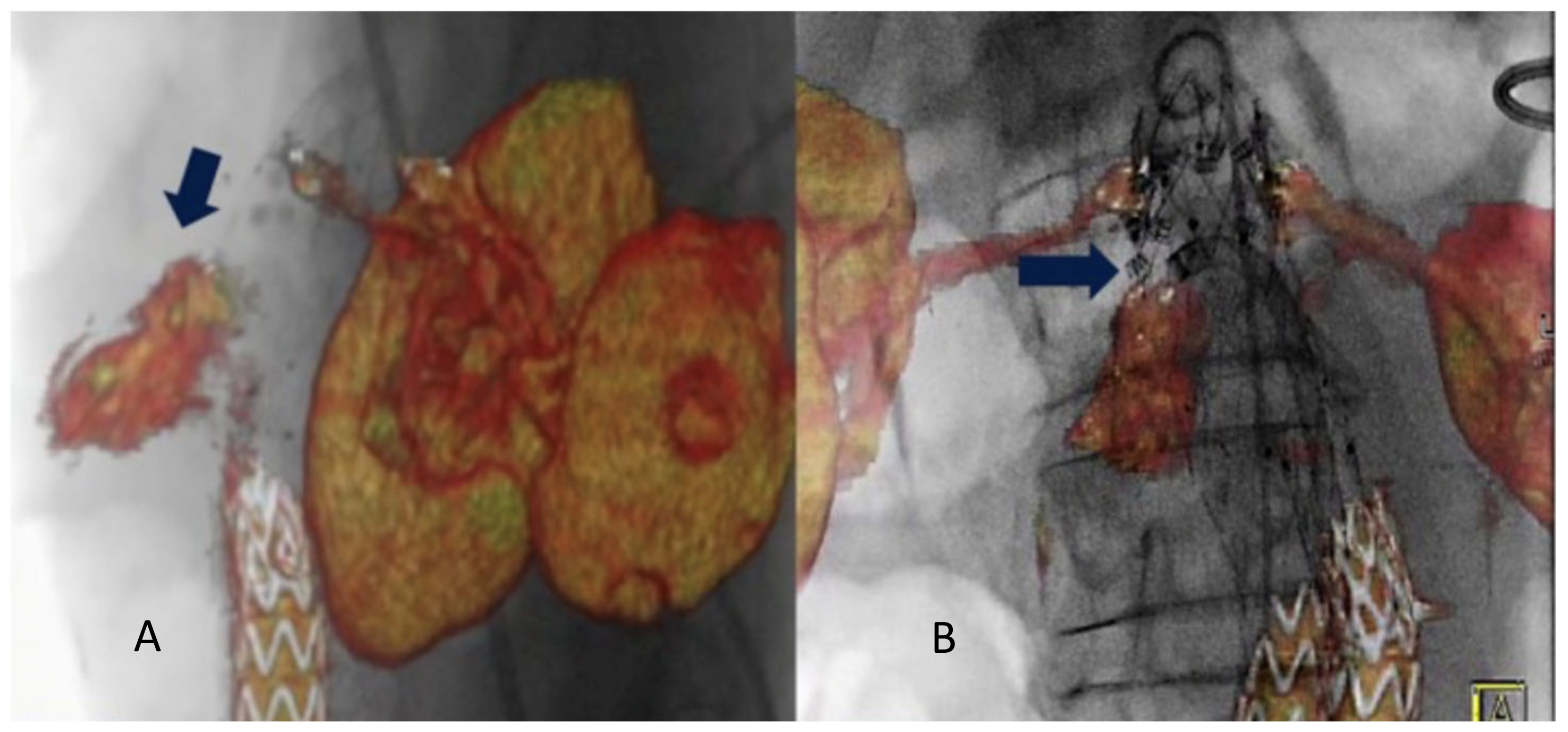
Other frequently reported benefits of hybrid rooms are the higher image quality and the available advanced imaging applications such as fusion imaging, which eases navigation and increases the accuracy of endografts deployment [2]. Fusion imaging provides a continuous display of the vascular structures without the need for fluoroscopy. This allows positioning of the gantry and table, choice of working C-arm angulations, and adjustment of collimation and magnification without x-ray use. This technique has significantly reduced contrast agent volume, radiation exposure, and procedure time compared with a standard endovascular repair procedure [1,26]. Two different registration methods can be used to obtain fusion images: the 2D–3D method and the 3D–3D method. The 3D–3D method has been shown to reduce the rate of secondary operations and their associated morbidity [27]. Chinnadurai et al. reported a higher accuracy using aortic wall calcifications-based vs spine-based image fusion during 3D–3D fusion for EVAR guidance [28]. However, Schulz et al. [5] have reported that the 3D–3D method requires a higher radiation dose and contrast agent injection. Our study obtained fusion registration with only two orthogonal fluoroscopic shots. This method is almost radiation-free. Routine use of this technology has contributed to increased short- and long-term technical success rates of all endovascular procedures, especially F-BEVAR [29]. Tenorio et al. observed a higher technical success rate when F-BEVAR was performed in a modern hybrid room with fusion imaging and CBCT and lower rates of 30-day mortality and early re-interventions [30]. In case of endovascular redo aortic repair (staged procedures or re-interventions), it is possible to use the redo fusion technique. As described, this technique uses the previously implanted devices as landmarks for the FI overlay. In the literature, only one case of type IA endoleak treatment with endo-anchors deployment under redo fusion guidance is reported [31] Figure 3.
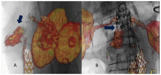
Figure 3.
Intraoperative projection of type IA endoleak channel (A). Positioning and deployment of the Heli-FX endo-anchors in the specific origin of the endoleak (arrow) for the “endosuture line” (B) from Tinelli et al. [31].
The present study established how, in real-time fusion imaging, the distance between the target vessel in 3D volume rendering and 2D fluoroscopy is effectively reduced by using endovascular markers to overlay the images. This is due to the proximity of the previously implanted marker (stent-graft, plugs, etc.) to the repair area, based on the intuitive concept that the closer the markers area, the lower the error rate of the fusion technique. At the same time, there is less use of contrast, also because the scaffold of the previously implanted prosthesis has several reference points to improve volume alignment during the fusion procedure itself.
In case of redo fusion, the markers are placed in the aorta or its principal branches, with more accurate overlay in terms of aortic spatial orientation. During endovascular aortic repair, the insertion of stiff guides and shafts modify the physiological aortic curvature. Therefore, it is essential to have markers that follow the adaptation of the vessel after the introduction of stiff guides, as in case of redo fusion. In this technique, the placed stent follows the “new” morphology of the vessel. Using the redo fusion technique, which utilizes the stent placed in the initial operation, allows the operator a greater orientation accuracy.
In addition, a high rate of accuracy of the redo fusion has been seen in the thorax; the discrepancy of the bone in the patient position during the pre-operative CTA (upper limbs in hyper-abduction) and the intra-operative position (arms adducted with the elbows extended) is overcome using endovascular markers.
In this context, redo fusion represents a high-precision technique compared with bone fusion, as the markers are not modified by the intra-operative setup. Our study showed that the accuracy was even higher when both the distance between fusion marker and target vessel was lower than 3 cm, and the aortic angle was greater or equal to 45°.
Several pathologies benefiting from this innovative fusion method following a previous operation have been identified, including descending thoracic aortic diseases (TEVAR), thoraco-abdominal aneurysms, type IA and type IB endoleak (F-BEVAR procedure) after EVAR and staged procedures of complex aortic diseases. Thus, redo fusion can be considered a highly refined method and currently represents a significant opportunity in endovascular redo surgery.
There are some limitations to this study. The study was observational, and the sample size was too small to draw strong conclusions. Moreover, advances could be made in image fusion registration workflow and the possible role of a learning curve was not analyzed.
5. Conclusions
In case of endovascular redo aortic procedures, a new registration protocol based on two single-frame images overlayed with previously implanted devices can be used. Support in endovascular re-interventions with 2D–3D IF can enable the safe alignment of anatomical structures shown in VR with 2D fluoroscopy, which can be accurately overlapped with landmarks from the previously placed stent graft. This redo fusion technique is accurate and allows the optimization of X-ray working views, supporting the endovascular navigation and vessel catheterization.
Author Contributions
Conceptualization, G.T. and Y.T.; methodology, G.T., F.M. and F.S.; formal analysis, F.D. and F.S.; data curation, S.S. and F.M.; writing—original draft preparation, S.S., F.S., F.D. and M.D.; writing—review and editing, G.T., F.M. and Y.T.; supervision, G.T. All authors have read and agreed to the published version of the manuscript.
Funding
This research received no external funding.
Data Availability Statement
Data sharing is not applicable to this article.
Conflicts of Interest
Fabrizio Minelli: none; Simona Sica: none; Federica Donato: none; Fadia Salman: none; May Dvir: none; Yamume Tshomba: consultant for Medtronic and Terumo Aortic; Giovanni Tinelli: consultant for Medtronic and Terumo Aortic.
References
- Hertault, A.; Maurel, B.; Sobocinski, J.; Gonzalez, T.; Azzaoui, R.; Midulla, M.; Haulon, S. Impact of Hybrid Rooms with Image Fusion on Radiation Exposure during Endovascular Aortic Repair. Eur. J. Vasc. Endovasc. Surg. 2014, 48, 382–390. [Google Scholar] [CrossRef] [PubMed]
- Tinelli, G.; Bonnet, M.; Hertault, A.; Sica, S.; Di Tanna, G.L.; Bianchini, A.; Fabre, D.; Sobocinski, J.; Haulon, S. Impact of Hybrid Operating Rooms on Long-Term Clinical Outcomes Following Fenestrated and Branched Endovascular Aortic Repair. J. Endovasc. Ther. 2021, 28, 415–424. [Google Scholar] [CrossRef] [PubMed]
- Van Schaik, T.G.; Blankensteijn, J.D.; Wisselink, W.; Nederhoed, J.H.; Lely, R.J.; Hoksbergen, A.W.J.; Yeung, K.K. Image Fusion During Standard and Complex Endovascular Aortic Repair, to Fuse or Not to Fuse? A Meta-analysis and Additional Data From a Single-Center Retrospective Cohort. J. Endovasc. Ther. 2021, 28, 78–92. [Google Scholar]
- National Council on Radiation Protection and Measurements. Implementation of the Principle of as Low as Reasonably Achievable (ALARA) for Medical and Dental Personnel. NCRP Report no. 107. Available online: http://www.ncrponline.org/Publications/Reports_100-119.html (accessed on 23 December 2022).
- Schulz, C.J.; Schmitt, M.; Böckler, D.; Geisbüsch, P. Feasibility and accuracy of fusion imaging during thoracic endovascular aortic repair. J. Vasc. Surg. 2016, 63, 314–322. [Google Scholar] [CrossRef] [PubMed]
- Edsfeldt, A.; Sonesson, B.; Rosén, H.; Petri, M.H.; Hongku, K.; Resch, T.; Dias, N.V. Validation of a New Method for 2D Fusion Imaging Registration in a System Prepared Only for 3D. J. Endovasc. Ther. 2020, 27, 468–472. [Google Scholar] [CrossRef]
- Wanken, Z.J.; Barnes, J.A.; Trooboff, S.W.; Columbo, J.A.; Jella, T.K.; Kim, D.J.; Khoshgowari, A.; Riblet, N.B.V.; Goodney, P.P. A systematic review and meta-analysis of long-term reintervention after endovascular abdominal aortic aneurysm repair. J. Vasc. Surg. 2020, 72, 1122–1131. [Google Scholar] [CrossRef] [PubMed]
- Budtz-Lilly, J.; Hongku, K.; Sonesson, B.; Dias, N.; Resch, T. Endovascular redo aortic surgery. J. Cardiovasc. Surg. 2017, 58, 854–860. [Google Scholar] [CrossRef]
- Tenorio, E.R.; Dias-Neto, M.F.; Lima, G.B.B.; Estrera, A.L.; Oderich, G.S. Endovascular repair for thoracoabdominal aortic aneurysms: Current status and future challenges. Ann. Cardio-Thorac. Surg. 2021, 10, 744–767. [Google Scholar]
- Schermerhorn, M.L.; Buck, D.B.; O’Malley, A.J.; Curran, T.; McCallum, J.C.; Darling, J.; Landon, B.E. Long-term outcomes of abdominal aortic aneurysm in the medicare population. N. Engl. J. Med. 2015, 373, 328–338. [Google Scholar] [CrossRef]
- Columbo, J.A.; Martinez-Camblor, P.; O’Malley, A.J.; Suckow, B.D.; Hoel, A.W.; Stone, D.H.; Schanzer, A.; Schermerhorn, M.L.; Sedrakyan, A.; Goodney, P.P. Society for Vascular Surgery’s Vascular Quality Initiative. Long-term Reintervention After Endovascular Abdominal Aortic Aneurysm Repair. Ann. Surg. 2021, 274, 179–185. [Google Scholar] [CrossRef]
- Duebener, L.; Hartmann, F.; Kurowski, V.; Richardt, G.; Geist, V.; Erasmi, A.; Sievers, H.-H.; Misfeld, M. Surgical interventions after emergency endovascular stent-grafting for acute type B aortic dissections. Interact. Cardiovasc. Thorac. Surg. 2007, 6, 288–292. [Google Scholar] [CrossRef]
- Lee, C.J.; Rodriguez, H.E.; Kibbe, M.R.; Malaisrie, S.C.; Eskandari, M.K. Secondary interventions after elective thoracic endovascular aortic repair for degenerative aneurysms. J. Vasc. Surg. 2013, 57, 1269–1274. [Google Scholar] [CrossRef]
- Hallett, J.W.; Marshall, D.M.; Petterson, T.M.; Gray, D.T.; Bower, T.C.; Cherry, K.J.; Gloviczki, P.; Pairolero, P.C. Graft-related complications after abdominal aortic aneurysm repair: Reassurance from a 36-year population-based experience. J. Vasc. Surg. 1997, 25, 277–286. [Google Scholar] [CrossRef]
- Pitoulias, G.A.; Schulte, S.; Donas, K.P.; Horsch, S. Secondary Endovascular and Conversion Procedures for Failed Endovascular Abdominal Aortic Aneurysm Repair: Can We Still Be Optimistic? Vascular 2009, 17, 15–22. [Google Scholar] [CrossRef]
- Resch, T.; Koul, B.; Dias, N.V.; Lindblad, B.; Ivancev, K. Changes in aneurysm morphology and stent-graft configuration after endovascular repair of aneurysms of the descending thoracic aorta. J. Thorac. Cardiovasc. Surg. 2001, 122, 47–52. [Google Scholar] [CrossRef]
- Matsumura, J.S.; Chaikof, E.L. Continued expansion of aortic necks after endovascular repair of abdominal aortic aneurysms. J. Vasc. Surg. 1998, 28, 422–431. [Google Scholar] [CrossRef]
- Hassoun, H.T.; Mitchell, R.S.; Makaroun, M.S.; Whiting, A.J.; Cardeira, K.R.; Matsumura, J.S. Aortic neck morphology after endovascular repair of descending thoracic aortic aneurysms. J. Vasc. Surg. 2006, 43, 26–31. [Google Scholar] [CrossRef]
- Schanzer, A.; Greenberg, R.K.; Hevelone, N.; Robinson, I.W.P.; Eslami, M.; Goldberg, R.J.; Messina, L.M. Predictors of Abdominal Aortic Aneurysm Sac Enlargement After Endovascular Repair. Circulation 2011, 123, 2848–2855. [Google Scholar] [CrossRef]
- Fulton, J.J.; Farber, M.A.; Sanchez, L.A.; Godshall, C.J.; Marston, W.A.; Mendes, R.; Rubin, B.G.; Sicard, G.A.; Keagy, B.A. Effect of challenging neck anatomy on mid-term migration rates in AneuRx endografts. J. Vasc. Surg. 2006, 44, 932–937. [Google Scholar] [CrossRef]
- Abbruzzese, T.A.; Kwolek, C.J.; Brewster, D.C.; Chung, T.K.; Kang, J.; Conrad, M.F.; LaMuraglia, G.M.; Cambria, R.P. Outcomes following endovascular abdominal aortic aneurysm repair (EVAR): An anatomic and device-specific analysis. J. Vasc. Surg. 2008, 48, 19–28. [Google Scholar] [CrossRef]
- Suckow, B.D.; Goodney, P.P.; Columbo, J.A.; Kang, R.; Stone, D.H.; Sedrakyan, A.; Cronenwett, J.L.; Fillinger, M.F. National trends in open surgical, endovascular, and branched-fenestrated endovascular aortic aneurysm repair in Medicare patients. J. Vasc. Surg. 2018, 67, 1690–1697. [Google Scholar] [CrossRef] [PubMed]
- McNally, M.M.; Scali, S.T.; Feezor, R.J.; Neal, D.; Huber, T.S.; Beck, A.W. Three-dimensional fusion computed tomography decreases radiation expo- sure, procedure time, and contrast use during fenestrated endovascular aortic repair. J. Vasc. Surg. 2015, 61, 309–316. [Google Scholar] [CrossRef] [PubMed]
- Tacher, V.; Lin, M.; Desgranges, P.; Deux, J.F.; Grünhagen, T.; Becquemin, J.P. Image guidance for endovascular repair of complex aortic aneurysms: Compari- son of two-dimensional and three-dimensional angiography and image fusion. J. Vasc. Interv. Radiol. 2013, 24, 1698–1706. [Google Scholar] [CrossRef] [PubMed]
- Dias, N.V.; Billberg, H.; Sonesson, B.; Törnqvist, P.; Resch, T.; Kristmundsson, T. The effects of combining fusion imaging, low-frequency pulsed fluoroscopy, and low-con- centration contrast agent during endovascular aneurysm repair. J. Vasc. Surg. 2016, 63, 1147–1155. [Google Scholar] [CrossRef]
- Dijkstra, M.L.; Eagleton, M.J.; Greenberg, R.K.; Mastracci, T.; Hernandez, A. Intraoperative C-arm cone-beam computed tomography in fenestrated/branched aortic endografting. J. Vasc. Surg. 2011, 53, 583–590. [Google Scholar] [CrossRef]
- Törnqvist, P.; Dias, N.; Sonesson, B.; Kristmundsson, T.; Resch, T. Intra-operative Cone Beam Computed Tomography can Help Avoid Reinterventions and Reduce CT Follow up after Infrarenal EVAR. Eur. J. Vasc. Endovasc. Surg. 2015, 49, 390–395. [Google Scholar] [CrossRef]
- Chinnadurai, P.; Chintalapani, G.; Bechara, C.F.; Bismuth, J.; Lumsden, A.B. 3D-3D Image Fusion for EVAR Guidance: Comparison of Spine-Based vs. Aortic Wall Calcification-Based Alignment. J. Vasc. Surg. 2015, 61, 139S–140S. [Google Scholar] [CrossRef]
- Sobocinski, J.; Chenorhokian, H.; Maurel, B.; Midulla, M.; Hertault, A.; Le Roux, M.; Azzaoui, R.; Haulon, S. The Benefits of EVAR Planning Using a 3D Workstation. Eur. J. Vasc. Endovasc. Surg. 2013, 46, 418–423. [Google Scholar] [CrossRef]
- Tenorio, E.R.; Oderich, G.S.; Sandri, G.A.; Ozbek, P.; Kärkkäinen, J.M.; Macedo, T.A.; Vrtiska, T.; Cha, S. Impact of onlay fusion and cone beam computed tomography on radiation exposure and technical assessment of fenestrated-branched endovascular aortic repair. J. Vasc. Surg. 2019, 69, 1045–1058.e3. [Google Scholar] [CrossRef]
- Tinelli, G.; De Nigris, F.; Flore, R.; Santoliquido, A.; Tshomba, Y. Endoanchors under 3D image fusion for a type IA endoleak after EVAR. Clin. Case Rep. 2019, 7, 529–532. [Google Scholar] [CrossRef]
Disclaimer/Publisher’s Note: The statements, opinions and data contained in all publications are solely those of the individual author(s) and contributor(s) and not of MDPI and/or the editor(s). MDPI and/or the editor(s) disclaim responsibility for any injury to people or property resulting from any ideas, methods, instructions or products referred to in the content. |
© 2023 by the authors. Licensee MDPI, Basel, Switzerland. This article is an open access article distributed under the terms and conditions of the Creative Commons Attribution (CC BY) license (https://creativecommons.org/licenses/by/4.0/).

