An Investigation into the Wear Behavior of Martensitically Transformed Nitrided Layers


1
Department Materials Technologies, Leibniz-Institut für Werkstofforientierte Technologien—IWT, 28359 Bremen, Germany
2
Faculty of Sciences and Technologies, Lorraine University, 54000 Nancy, France
3
Oerlikon Friction Systems GmbH, 28719 Bremen, Germany
4
MAPEX Center for Materials and Processes, University of Bremen, 28359 Bremen, Germany
*
Author to whom correspondence should be addressed.
Lubricants 2023, 11(11), 481; https://doi.org/10.3390/lubricants11110481
Submission received: 31 August 2023
/
Revised: 21 September 2023
/
Accepted: 2 November 2023
/
Published: 7 November 2023
(This article belongs to the Special Issue Advances in Plasma Surface Treatment and Modification)
Abstract
:To improve the service behavior of gears, surface heat treatments such as nitriding or induction hardening can be performed. Since these processes are limited in their achievable maximum hardness or depth of hardness, a combination treatment could allow benefits from the advantages of both processes. The aim of this work was to show the correlation between the microstructure resulting from combination treatment and the performance of the surface layer using the example of wear behavior. The investigations focused on the impact of different nitrided states, in the combination treatment of the material EN31CrMoV9, on wear resistance. The wear was evaluated after running the two-disc test gravimetrically and optically. Nitrided-only specimens showed better wear resistance compared to those subjected to induction hardening after nitriding. Substantial differences in weight loss indicate that induction hardening worsens the wear behavior. The variants with the compound layer removed in the nitride-only state as well as in the induction hardened state showed a better wear behavior compared to the respective conditions with a compound layer. This was attributed to the lower surface roughness and the higher hardness due to less retained austenite after combination treatment.
1. Introduction
Mechanical transmission components such as gears are often surface heat treated to extend their service life [1]. In addition to case hardening, which is often applied to low-alloyed gears to increase their surface hardness [2,3], nitriding and induction hardening are also suitable for this purpose [4,5,6,7,8].
Nitriding is a thermochemical surface heat treatment and is usually carried out at temperatures below the AC1 temperature by nitriding high hardness in the surface layer that can be reached by nitrogen enrichment of the material and the following precipitation of nitrides [9,10,11]. The nitrided layer consists of a few-micrometers thin nitride compound layer at the surface and an underlying diffusion zone. While the strength of nitrided components mainly depends on the diffusion zone, the wear and corrosion behavior is largely determined by the compound layer of nitrides that is formed on the very surface [12,13]. However, to achieve high nitriding hardness depths, due to the comparably low treatment temperature, treatment times of up to 200 h are necessary, which usually also result in a decrease in the strength of the base material and of the nitrided layer [14].
With induction heat treatment, on the other hand, high hardening depths can be achieved in only a few seconds [15]. In this process the hardness of the surface layer is increased by short-time austenitizing followed by quenching. The hardness and toughness of the hardened surface layer can then be specifically adjusted by tempering following induction hardening. The hardness profile after surface hardening generally exhibits a deep plateau at a high level. However, since no change is made to the chemical composition in only thermal surface treatments, the properties i.e., the maximum hardness that can be achieved, depend primarily on the carbon content of the treated material [16].
A combination treatment of nitriding and induction hardening can achieve high hardness depths in short treatment durations as an alternative to deep nitriding [17,18,19,20,21,22]. The process combination leads to an increase in hardness compared to the single treatments [19,23] due to an overlap of the increase in martensite hardness due to additional N atoms, precipitation hardening (by (carbo)nitrides) and fine grain size [23]. The achievable hardness also depends on the treated materials composition. In addition to the carbon content, the type and quantity of nitride-forming alloying elements of the treated material are decisive for the hardness increase, since the hardness increase depends on the type, quantity, size and distribution of (carbo)nitrides formed during nitriding and not dissolved during subsequent austenitization [24].
The compound layer is partially or completely decomposed during austenitization by nitrogen effusion as a result of the low nitrogen partial pressure at the workpiece surface. This results in an increase in the porosity at the very surface due to the formation of molecular nitrogen, and inner oxidation takes place [23,24,25]. Some approaches to avoid compound layer decomposition exist, using a low austenitizing temperature and a short austenitizing time [24]. Nevertheless, the compound layer undergoes a high thermal load, which can lead to crack formation in the compound layer.
When dissolving the compound layer, nitrogen is progressively released with increasing temperature, and the diffusion depth also increases [26]. Nitrogen loss from the compound layer results in the nitrogen concentration falling below the nitrogen solubility limit of the ε-carbonitride, thus austenite is formed during heating and retains during quenching depending on the nitrogen content [18].
A partial or complete decomposition of the compound layer during austenitization results in a layer with residual austenite forming below the (former) compound layer due to the high nitrogen concentration [24,25,26]. Furthermore, the corrosion resistance and the adhesive wear resistance are reduced if the compound layer no longer exists at the surface, since these properties are primarily determined by the compound layer [12].
Recent investigations have shown that negative effects such as pore formation and high amounts of retained austenite can be reduced by decreasing the compound layer thickness [17] and the process control during subsequent induction hardening [18].
This work was conducted to investigate the impact of the compound layer, which is no longer present after combination treatment, on the wear behavior. For this purpose, variations in the surface layer were investigated on the material EN31CrMoV9 using a two-disc test rig (Amsler test). Different nitriding treatments were used to vary the nitriding hardness depth and compound layer. The applied induction heat treatment parameters were kept constant. The wear was evaluated gravimetrically and optically using a confocal laser-scanning microscope (CLSM). In order to evaluate the wear behavior of the surface layers after the combination treatment, they were compared with corresponding nitrided-only conditions.
2. Materials and Methods
2.1. Investigation Materials
The investigations were carried out on the frequently used nitriding and heat treatable steel EN31CrMoV9 (for chemical composition see Table 1). For the wear tests, ring-shaped samples with an outer diameter of 46 mm, an inner diameter of 20 mm and a thickness of 8 mm were produced from the bar material, as also used in the previous studies on microstructure formed during nitriding and combination treatment [17,18]. Before applying the surface heat treatments, a preheat treatment was carried out to produce a homegeneous initial microstructure. The initial microstructure was a tempered martensite resulting from quenching (TA = 870 °C) and tempering at 630 °C for 2 h. The tempering temperature was selected to set a strength of about 1000 N/mm2, which is usual for gear applications. The initial hardness was about 324 HV10.
For the counterpart, the common cold-working steel ENX153CrMoV12 was used (for chemical composition see Table 1). The diameter of the counterpart is 50 mm. To avoid canting and reduce the contact area, the lateral surface had a crowned shape with a curvature radius of 5 mm. The counterparts were oil-quenched from 1080 °C and tempered three times for 2 h at 525 °C. The tempering temperature was selected above the secondary hardness maximum in order to completely precipitate the wear-resistant alloy carbides and thus achieve the hardest and most wear-resistant microstructure possible. The hardness of the counterparts was determined at approx. 699 HV10.
2.2. Surface Heat Treatment
2.2.1. Nitriding
For the investigations, pore-free compound layers with low thicknesses were produced with gas and plasma nitriding. Gas nitriding (see Table 2) was carried out in a pit-type furnace with controlled nitriding potential. In order to suppress the formation of a compound layer, the nitriding potential was chosen in the α-region following the Lehrer diagram [27]. Heating was carried out in an ammonia atmosphere to activate the sample surface. Cooling after nitriding was also performed with the addition of ammonia (phase-controlled cooling) to avoid nitrogen effusion and the resulting denitriding at the end of the process.
Plasma nitriding (see Table 3) was carried out in an industrial hot-wall furnace with a low nitrogen supply with the aim of producing compound layers in the γ‘-nitride region. The voltage used for the plasma nitriding experiments was 500 V, and the pressure was regulated to 4 mbar. The pulses had a pulse duration of 100 μs; the pulse pause was 200 μs. During heating, a hydrogen–argon plasma was ignited in the temperature range from 400 °C to 500 °C to clean and activate the sample surface. Cooling after plasma nitriding took place in an uncontrolled manner in the system.
Besides the compound layer, further variations in the nitrided layers were in the nitriding hardness depth (NHD). The NHD was determined at cross sections. The microstructural condition after the heat treatments was documented at metallographic cross sections (Figure 1). The characteristics of the nitrided layers (compound layer thicknesses (CLT)/nitriding hardness depths) are shown in Table 4. A detailed description of the microstructure of the nitrided layers can be found in [17].
In order to remove the compound layer, some samples were rotary barrel finished (trowalized) between plasma nitriding and induction hardening. These variants will be referred to as “PN1-CL” and “PN2-CL”.
2.2.2. Induction Heat Treatment
Induction hardening was carried out using a universal hardening system VL1000 SINAC 200/300 S MFC, manufactured by EFD Induction. The lateral surfaces of the disc specimens were heated with an inductor, which has an inner diameter of 50 mm, with high frequency (~200 kHZ) and a generator power of approx. 50 kW, for 1 s. Following induction heating, the samples were quenched with a polymer solution (12% aquatenside in water) in a continuous process.
Table 5 gives the hardening depth and the retained austenite amount at the surface after combination treatment. The hardening depth after induction hardening was determined at cross sections with a hardness limit of 424 HV1, which corresponds to a hardness of 100 HV1 above the hardness of the quenched and tempered condition. Since induction hardening has a significantly higher affected depth than nitriding, the total hardening depth of the combination treatment is determined by the parameters chosen for induction hardening. For the applied treatments, the hardening depth was approx. SHD = 1.0 mm after induction hardening only, as well as after the combination treatment.
The assessment of retained austenite content was conducted through X-ray diffraction, with a computer-controlled 3-circle 2θ diffractometer manufactured by GE Inspection Technology (Analytical X-ray MZ VI E XRD). This instrument utilized vanadium-filtered Cr-Kα radiation (with a wavelength λ(Kα12) of 0.2291 nm) at settings of 33 kV and 40 mA. The measurements were carried out using a primary beam collimator with a 1 mm diameter and a location-sensitive detector. The phase analysis spanned the 2θ range of 60–164°, employing a step size of 0.05° and requiring a measurement time of 1 h and 23 min. Quantitative assessment of the phases present was accomplished through Rietveld analysis using the Topas 4.2 software developed by Bruker-AXS, Karlsruhe [28].
Figure 2 shows the metallographical cross-sections of the six nitriding variants after induction hardening. The first thing to notice is that all variants have formed a dark oxide layer on the surface. In parts, this appears not to be closed, which may also be due to the preparation. The variants that were inductively heat treated with a compound layer show a darker shade in the area of the former compound layer. In this area pores were formed due to the released nitrogen. A more detailed description of the microstructure of the nitrided and induction-hardened layers can be found in [18].
The retained austenite detected in the first approx. 10 µm from the surface is not visible in the cross-sections, although the amount is up to 38 ma.%. The microstructure is very fine overall, so it is assumed that the retained austenite is finely distributed.
2.2.3. Experimental Design
Figure 3 illustrates the testing plan as a flow chart. The wear tests were performed for the as-nitrided state as well as for the combination treatment of nitriding and subsequent induction hardening. Inductive heat treatment was applied in the as-nitrided state for all nitriding variants DZ1, DZ2, PN1, PN2. Additionally the plasma nitrided variants PN1 and PN2 were induction hardened after removing the compound layer via barrel finishing.
2.3. Wear Testing
2.3.1. Two-Disc Test Rig
The wear behavior of the differently surface-heat-treated test discs was tested using the Amsler test (two-disc test rig) against discs made of hardened X153CrMoV12. In the test rig, the two discs were fixed on two driven shafts so that they were in contact with each other. The different sliding surface geometries results in an elliptical contact surface. The radial contact force was 50 N, which corresponds to a Hertz’sian pressure of approximately 1320 MPa. The two drive shafts of the test rig run in opposite directions, with the lower disc (sample) rotating at 1.1 times the speed of the upper disc (counterpart).
The tests were carried out without lubrication at room temperature as nitrided layers are suitable for use under insufficient lubrication and have good resistance to fretting, which is typical for unlubricated conditions. Since the tests were performed during the same test period, the climatic conditions were similar. A slight temperature increase in the discs was observed during the test, but the temperature could not be recorded. Active cooling was also not possible as the test rig has no temperature control option. During the interruptions to the test to determine the progress of wear, the discs cooled down completely. In order to perform the tests in a reasonable time schedule, a specimen speed of approximately 110 min−1 was set. The specimens were weighed after a wear distance of 250 m, 500 m, 1000 m, 1500 m and 2500 m to determine the mass loss. After 250 m and 2500 m, additional images of the wear lines were taken with a confocal laser microscope (CLSM, 3D Keyence VK-X1000, Keyence Deutschland, Neu-Isenburg, Germany).
To further characterize the surface, the roughness Sa of the wear track and the initial surface were also determined according to the standard DIN EN ISO 25178 [29]. The chosen magnification was 50x and the Gaussian filters were set to λS = 0.8 µm and λL = 0.5 mm.
For the presented investigations into the wear behavior, additional near-surface microhardness profiles were obtained by means of instrumented indentation testing.
2.3.2. Determination of the Wear Coefficients
Regarding the specimens, the depth tmax, width d and cross-sectional area AV of the wear track (see Figure 4) were determined from the images. The values were sampled at four different points of the wear track at angles of 0°, 90°, 180° and 270°, respectively (see Figure 4).
The wear coefficients for the specimens were calculated from the optical measurements according to DIN EN 1071-13 [30] with the help of the cross-sectional area using Equations (1) and (2).
- with VV→wear volume in mm3
- r→radius of the wear track in mm
- AV→wear area in mm2
- KS→wear coefficient of the specimen in mm3/Nm
- FN→normal force in N
- L→sliding distance in m
3. Results
3.1. Surface Roughness
Figure 5 shows the surface roughness after nitriding and after the combination heat treatment of nitriding and subsequent induction hardening. When looking at the nitrided-only conditions, it is noticeable that the gas-nitrided variants DZ1 and DZ2 with a very thin, partially unclosed compound layer exhibit lower roughness than the plasma-nitrided variants PN1 and PN2 with a 3–4 µm thick compound layer. During nitriding, a phase transformation takes place directly at the surface during compound layer formation (iron transforms into iron nitride), which is associated with a volume change. The higher roughness after plasma nitriding is therefore very likely to be due to the fact that the volume change at the thicker compound layer has a bigger impact on the surface structure.
Again, the grinding process to remove the compound layer significantly improves the roughness of the nitrided surfaces (PN1-CL and PN2-CL).
The subsequent induction heat treatment always leads to an increase in the roughness parameter Sa for all variants compared to the initial nitrided condition, but the amount of increase is not constant for all variants. Therefore, an interaction between the effect of induction hardening and the prior surface condition seems to take place.
The increase in roughness due to induction hardening is related to the changes in microstructure during inductive heating and subsequent quenching. The surface layer undergoes two phase transformations: during heating, the compound layer and the underlying diffusion zone are transformed into a nitrogen-rich austenite, which in turn becomes martensite during quenching.
3.2. Microhardness
The microhardness was determined close to the surface at a distance of 10 µm from the surface at the cross-sections. Figure 6 shows the results of the hardness indentations after nitriding with and without subsequent induction hardening. It should be noted that all hardness indentations are located in the diffusion zone, since the compound layers of the variants with compound layer (DZ1, DZ2, PN1 and PN2) are 3 µm and thinner.
In the nitrided state, the hardness of the diffusion layer is the result of the hardness of the basic microstructure (in this case a tempered martensite) and the hardening achieved by the precipitated nitrides. The specimens that were nitrided for 20 h (DZ2, PN2 and PN2-CL), and thus have a higher hardening depth than those that were nitrided for only 8 h (DZ1, PN1 and PN1-CL), have a higher hardness near the surface after nitriding. This is due to the drop in hardness at larger depths.
When the nitrides in the compound layer and the diffusion zone are inductively heated, they are dissolved because they are no longer stable at such high temperatures. The nitrogen is dissolved in the austenite and, like the carbon in the martensite, can be forcibly dissolved during the subsequent martensitic transformation and contribute to an increase in the martensite hardness. In fact, an increase in hardness caused by the subsequent induction hardening was only observed for the nitrided condition PN1-CL. Here, the near surface hardness after the combination treatment was more than 1100 Vickers. For the nitrided condition DZ1, a hardness of only about 600 Vickers was detected near the surface, which shows a clear decrease compared to the nitrided-only state.
3.3. Weight Loss
Figure 7 shows the evolution of the weight loss of the specimens for all nitrided layer variants, in each case in direct comparison to the nitrided-only initial condition with surface layer after the combination treatment. Additionally, the values of the weight loss after a sliding distance of 250 m and 2500 m are given in Table 6.
As can be seen from Table 6, at the beginning of the wear test (after 250 m sliding distance), for all nitrided layer variants, the wear behavior of the nitrided-only state (N) is much better than that of the nitrided and induction-hardened state (N + IH). In the evolution of the wear (Figure 7), it can clearly be seen that the curves of the nitride-only specimens at the beginning of the test are much flatter than those of the nitrided and induction-hardened specimens. This trend is independent of whether a compound layer is present or not. At the end of the wear test, the difference between the as-nitrided state and the surface after combination treatment is not so clear anymore. For the variant PN2 and the two variants without compound layer PN1-CL and PN2-CL, the weight loss after 2500 m was even lower after nitriding and subsequent induction hardening.
3.4. Wear Coefficients
Figure 8 shows the wear coefficients calculated from the cross-sectional area of the wear tracks after 250 m, which corresponds to the first stage of the wear test. Regarding the nitrided-only specimens at this early stage, the two technical-compound-layer-free variants DZ1 and DZ2 as well as the plasma nitrided variant PN2 have the highest wear coefficients in the as-nitrided state. The lowest wear coefficient was obtained for the plasma-nitrided variant PN1. Removing the compound layer decreases the wear coefficient for variant PN2, whereas that of variant PN1 is increased.
After induction hardening of the nitrided specimens, there is no clear tendency for the martensitic hardening to impact the wear coefficient. For the variants DZ2, PN1, PN1-CL and PN2-CL, the wear coefficient increases after induction hardening, while the wear coefficient of the induction hardened variants DZ1 and PN2 is decreased compared to the as-nitrided state.
Figure 9 shows the wear coefficients after 2500 m sliding distance. It is remarkable that the calculated wear coefficients for the nitrided-only variants (with except of variant PN2-CL) are very similar. The subsequent induction hardening decreases the wear coefficient for the variants DZ1, PN1, PN2 and PN1-CL, while those of variants DZ2 and PN2-CL increase.
4. Discussion
The wear behavior, which was the main focus of this work, was evaluated gravimetically and by optical measurements using CLSM. Both methods were used at the beginning of the wear test, after a sliding distance of 250 m, to compare the initial wear, and again after 2500 m sliding distance, which corresponds to the end of the test.
4.1. Wear Behavior of the Nitrided Only Condition
Nitrided layers are known for their good wear resistance, which results from the few-micrometer thin compound layer of iron nitrides present at the surface [12]. In the nitrided-only condition, two variants with a compound layer of 1–2 µm thickness (DZ1 and DZ2), two variants with a compound layer of about 3 µm thickness (PN1 and PN2) and two variants without a compound layer (PN1-CL and PN2-CL) were investigated.
Unexpectedly, the variants without compound layer showed lower weight losses than the variants with compound layer, both at the beginning of the test (250 m) and at the end (2500 m). The wear coefficients of these variants are also lower than those of the variants with a compound layer, which also stands in contradiction to the investigations in [31], which were carried out on the nitrided material 42CrMo4. The reason for the good behavior at the beginning of the test is presumably the low surface roughness achieved by grinding off the compound layer. At the end of the wear test, the roughness should no longer have such a great influence, since the initial surface has already worn off. This correlation can be found from the weight loss as well as from the wear coefficients that were calculated from the cross-sectional area of the wear track.
Regarding the variants with compound layer, PN1 with a compound layer of about 3 µm thickness is outstanding. After a sliding distance of 250 m a weight loss was hardly detectable and the corresponding wear coefficient, which resulted from the optical evaluation was also very low. In comparison, the other variant with a similar compound layer thickness (PN2) showed a higher weight loss and also a higher wear coefficient after the first 250 m sliding distance. Figure 10 shows representative images of the profile lines at two of the measuring positions for these two variants. The appearance of the wear track is quite different: for PN1 no distinct profile has developed at this time of the wear test (Figure 10a,b), whereas a clear wear track is visible for PN2 (Figure 10c,d). The depth of the wear track is in the range of the compound layer thickness, so it can be concluded, that the compound layer of variant PN2 is already worn off after a sliding distance of 250 m. At the end of the wear test the weight losses, as well as the wear coefficients, of variants PN1 and PN2 are very similar. It is assumed that the different behavior at the beginning of the wear test is due to an earlier failure of the compound layer of specimen PN2.
The two variants with a very thin compound layer are not noticeable. Due to the low thickness of the compound layer, which is, in addition, partially not closed, there is no reliable wear protection. This is underlined by the high wear coefficients already seen after a sliding distance of 250 m. The values are comparable to or higher than that of the variant PN2, where the compound layer was already worn off. At the end of the wear test the wear coefficients of all nitrided variants are at a similar level. The different hardening depths seem to have no impact in this experimental setting.
4.2. Wear Behavior of the Nitrided and Induction Hardened Condition
After induction hardening the compound layer developed during nitriding is no longer present. Instead, the microstructure consists of a nitrogen rich fine martensite with finely distributed nitrogen-stabilized austenite. For a direct comparison of the wear behavior, all six variants that were discussed for the nitrided only condition were also investigated after subsequent induction hardening.
All variants show an increased weight loss at the beginning of the wear test (250 m sliding distance). This is assumed to be a consequence of the missing compound layer at the surface in combination with an increase in the surface roughness due to the volume change during the phase transformations.
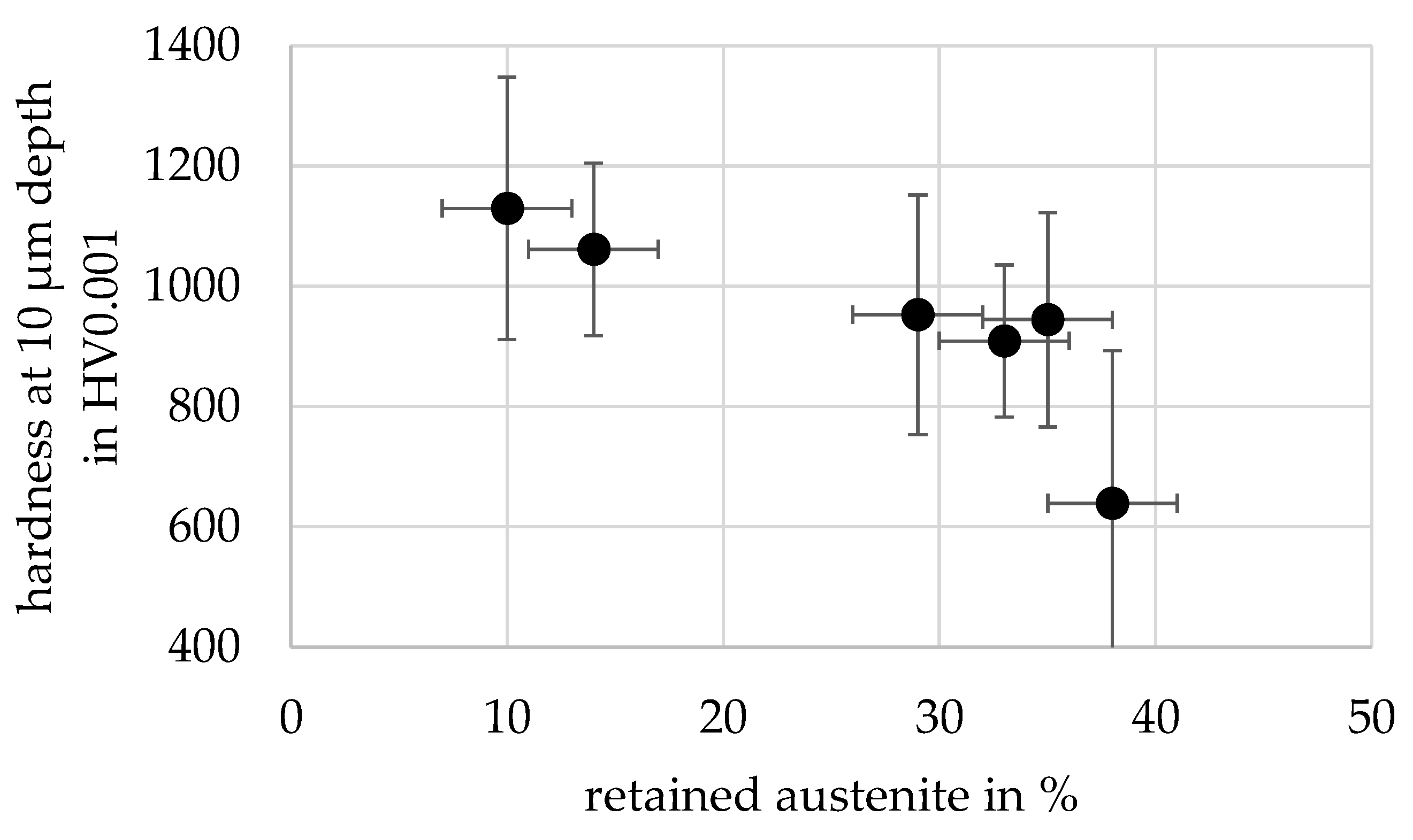
At the end of the wear test no clear correlation between induction hardening and wear behavior can be found from the wear coefficients. Regarding the weight losses, it is noticeable that the specimens that were induction hardened with a compound layer (DZ1, DZ2 and PN1) show a higher loss of weight compared to the corresponding variants that were only nitrided. The only exception is the PN2 variant, where the weight loss after 2500 m sliding distance for the nitrided and induction-hardened variant is lower than for the only nitrided variant. The specimens with the compound layer removed prior to induction heat treatment (PN1-CL and PN2-CL) show a lower weight loss than the nitrided-only specimens. This could be attributed to the hardness of the surface layer. Although for martensitic hardening after nitriding, additional nitrogen is present in the surface layer besides the carbon from the base material; for most variants a lower hardness is observed in the surface hardness plot in Figure 6 compared to the nitrided layer. This is related to the high amount of retained austenite that was determined near the surface. In Figure 11, therefore, the surface hardness is shown as a function of the retained austenite content from Table 5. The trend clearly shows that, with an increasing amount of retained austenite, a decrease in the surface hardness occurs. The highest surface hardness was determined for the two variants without a compound layer, which exhibit a much-less-retained austenite near the surface after induction hardening due to the lack of a nitrogen-rich compound layer.
5. Summary
The presented work investigated the effects of nitriding and subsequent induction hardening on the wear behavior of treated EN31CrMoV9 specimens in comparison with nitrided-only specimens. The wear was quantified gravimetrically and by optical measurements on the wear track. The results of the two methods differ slightly. While a significantly higher mass loss was observed at the beginning of the process for the nitrided and induction hardened specimens than for the nitrided-only specimens, no clear trend can be seen in the wear coefficients with respect to the effect of subsequent induction hardening. Although the weight loss shows a clearer impact of the subsequent induction hardening, it should be mentioned that large deviations during the weight measurements and the two decimal digits of the milligram range considered here are not reliable. Differences in the hundredths to tenths of a milligram range are therefore within the accuracy of weight measurement. Nevertheless, after a 250 m sliding distance, the difference in weight loss between the nitrided-only specimens and the corresponding specimens, which were nitrided and induction hardened, ranges from approx. 1 mm up to approx. 2.4 mg, so it can be concluded that the subsequent induction hardening worsens the initial wear behavior of the nitrided specimens. Over a longer duration (2500 m sliding distance), wear coefficients varied, but the subsequent induction hardening consistently worsened wear behavior in comparison to the nitrided-only state if the compound layer is not removed before induction heat treatment. The nitrided variants with the compound layer ground-off showed favorable wear behavior, attributed to the combined effects of reduced roughness achieved through grinding and higher surface hardness due to less retained austenite. In summary, the presence or absence of compound layers and induction hardening had varying effects on wear behavior, with initial surface conditions, surface roughness and retained austenite content playing significant roles in the wear performance of the tested materials.
6. Conclusions
The main conclusion from the presented investigations is that the surface layers produced by the combination of nitriding and induction hardening showed similar wear behavior compared to the nitrided only variants, although the hard an wear resistant compound layer was decomposed during inductive heat treatment. From the results the following conclusions can be drawn.
For the nitrided only condition:
- Variants without compound layers initially showed better wear resistance due to lower surface roughness.
- PN1 with a 3 µm compound layer excelled initially, while PN2 wore out its layer quickly.
- All nitrided variants had similar wear behavior when the compound layer was worn off.
For the nitrided and induction hardened condition:
- All variants showed increased initial wear due to the absence of the compound layer.
- Variants induction-hardened with a compound layer mostly had higher wear due to retained austenite and the resulting lower hardness, except for PN2.
- Removing the compound layer prior to induction hardening reduced retained austenite and in consequence wear.
- Surface hardness correlated with retained austenite content.
Author Contributions
Conceptualization, S.H.; methodology, S.H. and H.H.; investigation, S.H., H.H. and B.K.B.; writing—original draft preparation, S.H. and B.K.B.; writing—review and editing, J.E.; supervision, S.H., H.H. and J.E.; project administration, S.H.; funding acquisition, S.H. All authors have read and agreed to the published version of the manuscript.
Funding
The authors gratefully acknowledge support from the Arbeitsgemeinschaft Wärmebe-handlung und Werkstofftechnik e. V. The project IGF 21050 N was funded by the AiF (Arbeitsgemeinschaft industrieller Forschungsvereinigungen „Otto von Guericke“ e. V.) trough financial ressources from the BMWK (Bundesministerium für Wirtschaft und Klimaschutz).
![Lubricants 11 00481 i001]()

Data Availability Statement
Not applicable.
Acknowledgments
The authors would like to thank the technical staff from the Leibniz-Institut für Werkstofforientierte Technologien—IWT for their support.
Conflicts of Interest
For commercial affiliations, all authors must be accounted for. Author H.H. is employed by the company Oerlikon Friction Systems GmbH. While the research was conducted, he was employed at the Leibniz-Institut für Werkstofforientierte Technologien—IWT. The authors declare no conflict of interest. The funders had no role in the design of the study, in the collection, analyses, or interpretation of data, in the writing of the manuscript or in the decision to publish the results.
References
- Boniardi, M.; D’Errico, F.; Tagliabue, C. Influence of carburizing and nitriding on failure of gears—A case study. Eng. Fail. Anal. 2006, 13, 312–339. [Google Scholar] [CrossRef]
- Steinbacher, M.; Surm, H.; Clausen, B.; Lübben, T.; Hoffmann, F. Systematische Untersuchung verschiedener Einflussgrößen auf die Maß- und Formänderungen von einsatzgehärteten Stirnrädern. HTM J. Heat Treat. Mater. 2012, 67, 65–78. [Google Scholar] [CrossRef]
- Steinbacher, M.; Hoffmann, F.; Zoch, H.-W.; Lombardo, S.; Tobie, T. Neue Randschichtgefüge carbonitrierter Bauteile und deren Festigkeitseigenschaften: Teil 1: Untersuchungen werkstofftechnischer Eigenschaften. HTM J. Heat Treat. Mater. 2015, 70, 201–217. [Google Scholar] [CrossRef]
- Koenig, J.; Tobie, T.; Stahl, K. Nitriding of Heavily Loaded Gears—Potentials and Challenges. In Proceedings of the ECHT—European Conference on Heat Treatment Nitriding and Nitrocarburising, Friedrichshafen, Germany, 12–13 April 2018; pp. 45–50. [Google Scholar]
- Nöbauer, R.; Mozden, G.; Dallhammer, G.; Jansson, M. Nitriding of lightweight gears for space applications—A real challenge. In Proceedings of the ECHT—European Conference on Heat Treatment Nitriding and Nitrocarburising, Friedrichshafen, Germany, 12–13 April 2018; pp. 51–56. [Google Scholar]
- Sitzmann, A.; Tobie, T.; Stahl, K.; Schurer, S. Influence of the Case Properties After Nitriding on the Load Carrying Capacity of Highly Loaded Gears. In Proceedings of the ASME International Design Engineering Technical Conferences and Computers and Information in Engineering Conference, Anaheim, CA, USA, 18–21 August 2019. [Google Scholar]
- Hoja, S.; Geitner, M.; Zornek, B.; Hoffmann, F.; Tobie, T.; Stahl, K.; Fechte-Heinen, R. Influence of the Nitrided Layer Structure on the Micro-Pitting and Wear Behavior of Slow-Running Nitrided External Gears. Lubricants 2022, 10, 88. [Google Scholar] [CrossRef]
- Dobler, F. Einflüsse auf die Tragfähigkeit Induktiv Umlaufgehärteter Stirnräder. Ph.D. Thesis, TU München, Munich, Germany, 2018. [Google Scholar]
- Jonck, R.; Kunze, G. Gefügeausbildung und Härte von Verbindungs- und Diffusionsschichten bad- und gasnitrierter Werkzeugstähle. Z. Wirtsch. Fabr. 1978, 73, 213–220. [Google Scholar]
- Jonck, R.; Kunze, G. Gefügeausbildung und Härte von Verbindungs- und Diffusionsschichten bad- und gasnitrierter Baustähle. Z. Wirtsch. Fabr. 1979, 74, 445–454. [Google Scholar] [CrossRef]
- Hoffmann, R.; Mittemeijer, E.J.; Somers, M.A.J. Verbindungsschichtbildung beim Nitrieren und Nitrocarburieren: Deutung der Nitridbildung, der Diffusion, Porenbildung und Kohlenstoffanreicherung. HTM Härterei Tech. Mitt. 1996, 51, 162–169. [Google Scholar] [CrossRef]
- Hoffmann, F.; Bujak, I.; Mayr, P.; Löffelbein, B.; Gienau, M.; Habig, K.-H. Verschleißwiderstand nitrierter und nitrocarburierter Stähle. HTM Härterei Tech. Mitt. 1997, 52, 376–386. [Google Scholar] [CrossRef]
- Ebersbach, U.; Vogt, F.; Naumann, J.; Zimdars, H. Lochfraßbeständigkeit von oxidierten Verbindungsschichten in Abhängigkeit vom (N+C)-Gehalt der ε-Phase. HTM Härterei Tech. Mitt. 1999, 54, 241–248. [Google Scholar] [CrossRef]
- Hoja, S.; Hoffmann, F.; Steinbacher, M.; Zoch, H.-W. Investigation of the Tempering Effect during Nitriding. HTM J. Heat Treat. Mater. 2018, 73, 335–343. [Google Scholar] [CrossRef]
- Stiele, H.; Marquis, F. An overview of inductive gear hardening. In Proceedings of the International Symposium on Heating by Electromagnetic Sources, Padua, Italy, 19–22 June 2007; pp. 183–195. [Google Scholar]
- Vöhringer, O.; Macherauch, E. Struktur und mechanische Eigenschaften von Martensit. HTM Härterei Tech. Mitt. 1977, 32, 153–202. [Google Scholar] [CrossRef]
- Hoja, S.; Nadolski, D.; Steinbacher, M.; Fechte-Heinen, R. Optimized Nitriding for Subsequent Induction Heat Treatment. HTM J. Heat Treat. Mater. 2021, 76, 261–272. [Google Scholar] [CrossRef]
- Hoja, S.; Haupt, N.; Steinbacher, M.; Fechte-Heinen, R. Martensitic Induction Hardening of Nitrided Layers. HTM J. Heat Treat. Mater. 2022, 77, 393–408. [Google Scholar] [CrossRef]
- Kulka, M.; Panfil, D.; Michalski, J.; Wach, P. The effects of laser surface modification on the microstructure and properties of gas-nitrided 42CrMo4 steel. Opt. Laser Technol. 2016, 82, 203–219. [Google Scholar] [CrossRef]
- Panfil, D.; Kulka, M.; Wach, P.; Michalski, J.; Przestacki, D. Nanomechanical properties of iron nitrides produced on 42CrMo4 steel by controlled gas nitriding and laser heat treatment. J. Alloys Compd. 2017, 706, 63–75. [Google Scholar] [CrossRef]
- Panfil, D.; Kulka, M.; Wach, P.; Michalski, J. Microstructure and wear resistance of gas-nitrided 42CrMo4 steel after laser modification. J. Achiev. Mater. Manuf. Eng. 2017, 85, 12–20. [Google Scholar] [CrossRef]
- Panfil-Pryka, D.; Kulka, M.; Makuch, N.; Michalski, J.; Dziarski, P. The Effect of Temperature Distribution During Laser Heat Treatment of Gas-Nitrided 42CrMo4 Steel on the Microstructure and Mechanical Properties. Coatings 2020, 10, 824. [Google Scholar] [CrossRef]
- Bergmann, H.W.; Müller, D.; Amon, M.; Domes, J. Kombination des Laserstrahlhärtens mit einer Kurzzeitnitrierbehandlung. HTM Härterei Tech. Mitt. 1993, 48, 238–248. [Google Scholar] [CrossRef]
- Keidel, C. Nitrocarburieren Plus Induktives Randschichthärten. Ph.D. Thesis, TU Berlin, Berlin, Germany, 1995. [Google Scholar]
- Zenker, R. Kombinierte thermochemische/Hochgeschwindigkeitsbehandlung—Einige Grundlagen und Behandlungsergebnisse. Neue Hütte 1986, 31, 1–6. [Google Scholar]
- Zenker, R. Kombiniertes Nitrocarburieren/Widerstandshärten bzw.—Vergüten des Stahles 50CrV4. HTM Härterei Tech. Mitt. 1988, 43, 5–15. [Google Scholar]
- Spies, H.-J.; Berg, H.-J.; Zimdars, H. Fortschritte beim sensorkontrollierten Gasnitrieren. HTM J. Heat Treat. Mater. 2003, 58, 189–197. [Google Scholar]
- Epp, J. XRD Methods for Materials Characterization in Material Characterization Using Nondestructive Evaluation (NDE) Methods; Woodhead Publishing: Cambridge, UK, 2016; pp. 81–124. [Google Scholar]
- DIN EN ISO 25178-1:2016-12; Geometrical Product Specifications (GPS)—Surface Texture: Areal—Part 1: Indication of Surface Texture. ISO: Geneva, Switzerland, 2016.
- DIN EN 1071-13:2010-07; Advanced Technical Ceramics—Methods of Test for Ceramic Coatings—Part 13: Determination of Wear Rate by the Pin-on-Disk Method. Beuth Verlag: Berlin, Germany, 2010.
- Hoja, S.; Baustert, R.; Hasselbruch, H.; Steinbacher, M.; Fechte-Heinen, R. Investigation of combined surface treatments and coatings to increase the wear behavior of heat treatable steels. Surf. Coat. Technol. 2023, 472, 129929. [Google Scholar] [CrossRef]
Figure 1.
Cross-sections (etched with nital) of the different nitrided conditions (a) DZ1; (b) DZ2; (c) PN1; (d) PN2.
Figure 1.
Cross-sections (etched with nital) of the different nitrided conditions (a) DZ1; (b) DZ2; (c) PN1; (d) PN2.
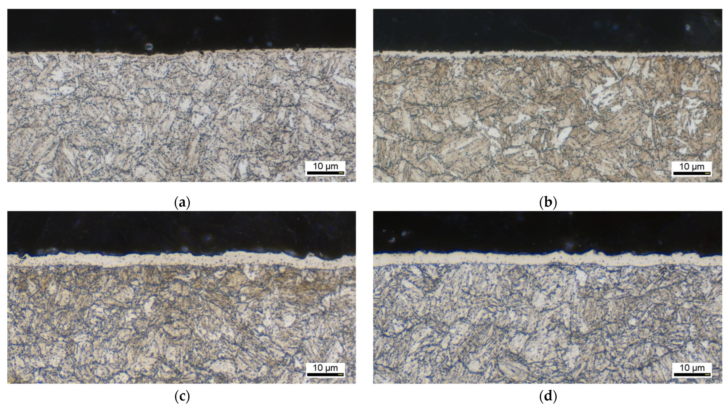
Figure 2.
Cross-sections (etched with nital) of the near surface area after induction hardening of different nitrided conditions (a) DZ1; (b) DZ2; (c) PN1; (d) PN2; (e) PN1-CL; (f) PN2-CL.
Figure 2.
Cross-sections (etched with nital) of the near surface area after induction hardening of different nitrided conditions (a) DZ1; (b) DZ2; (c) PN1; (d) PN2; (e) PN1-CL; (f) PN2-CL.
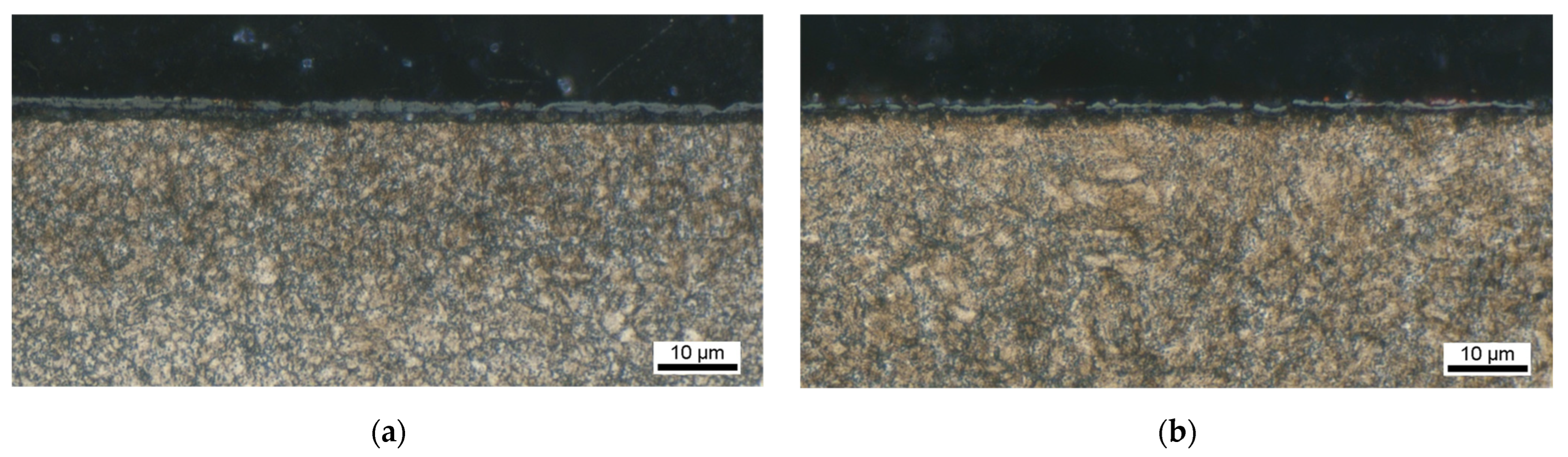
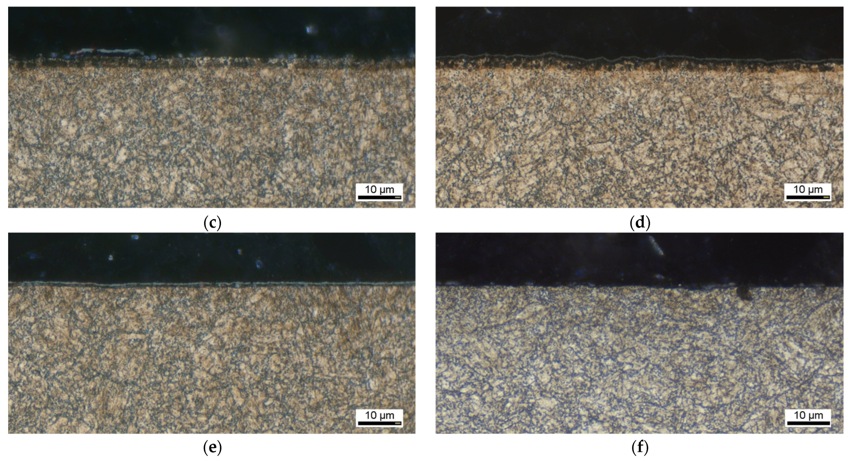
Figure 3.
Surface variants for the wear test.
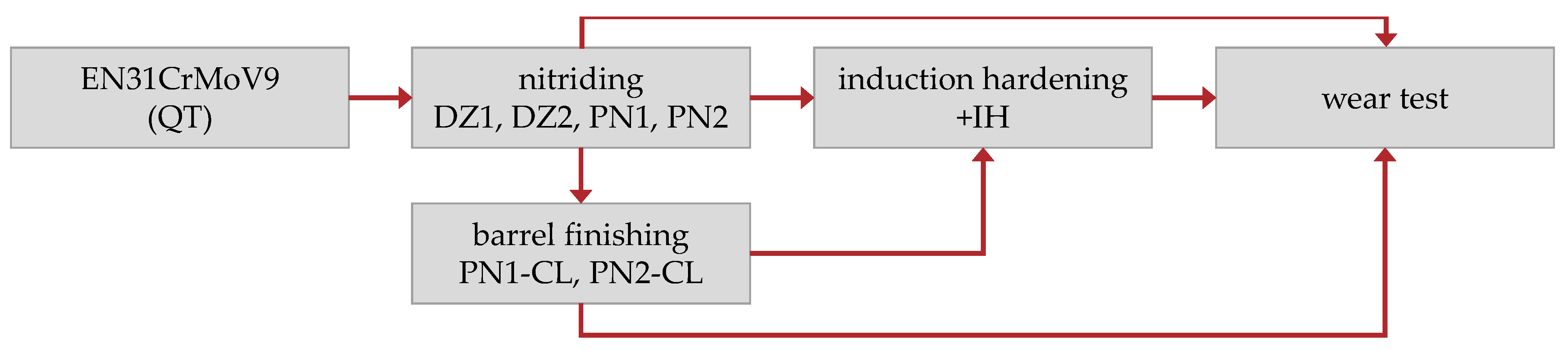
Figure 4.
(a) Schematic wear track geometry of the specimens; (b) sampling at four different points of the wear track (example cross-sectional area AV).
Figure 4.
(a) Schematic wear track geometry of the specimens; (b) sampling at four different points of the wear track (example cross-sectional area AV).
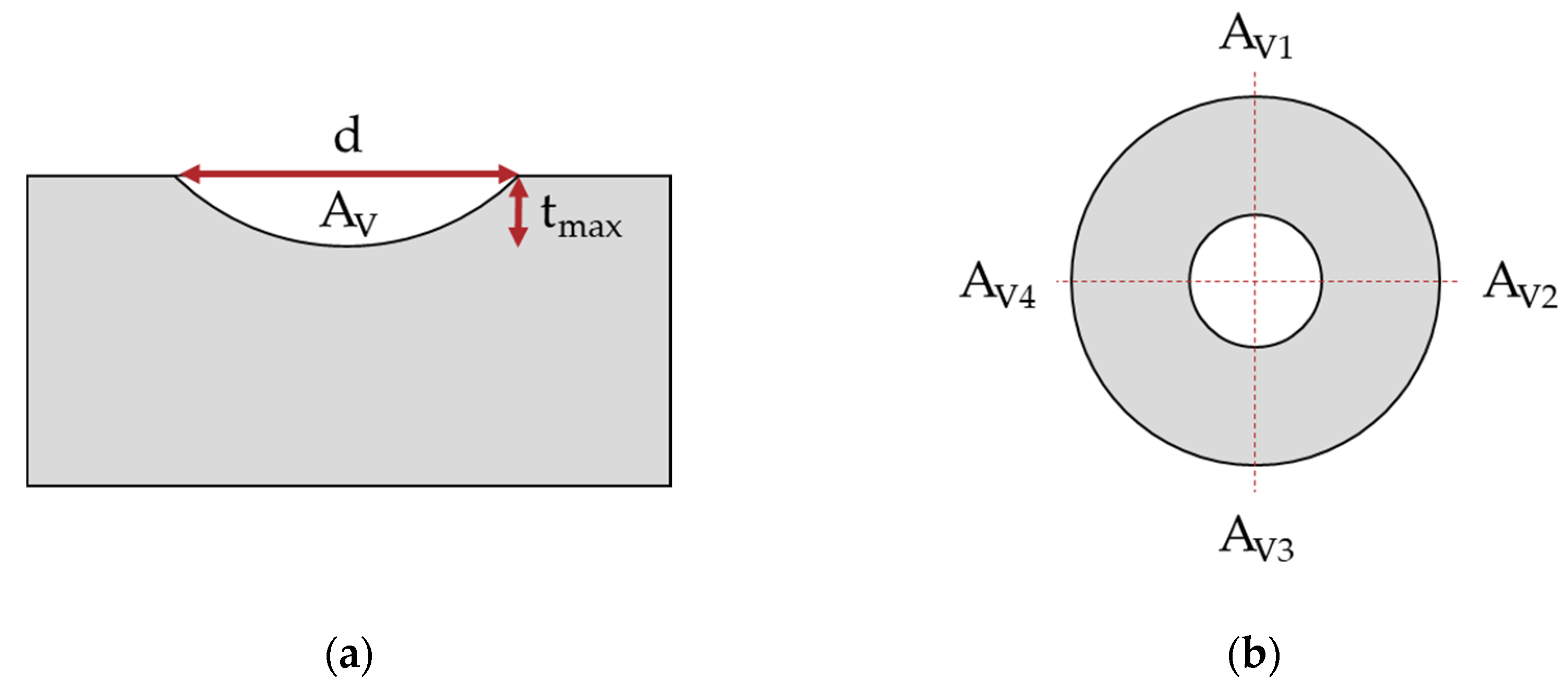
Figure 5.
Surface roughness Sa after nitriding and combination treatment (measured by CLSM with a 50× magnification).
Figure 5.
Surface roughness Sa after nitriding and combination treatment (measured by CLSM with a 50× magnification).
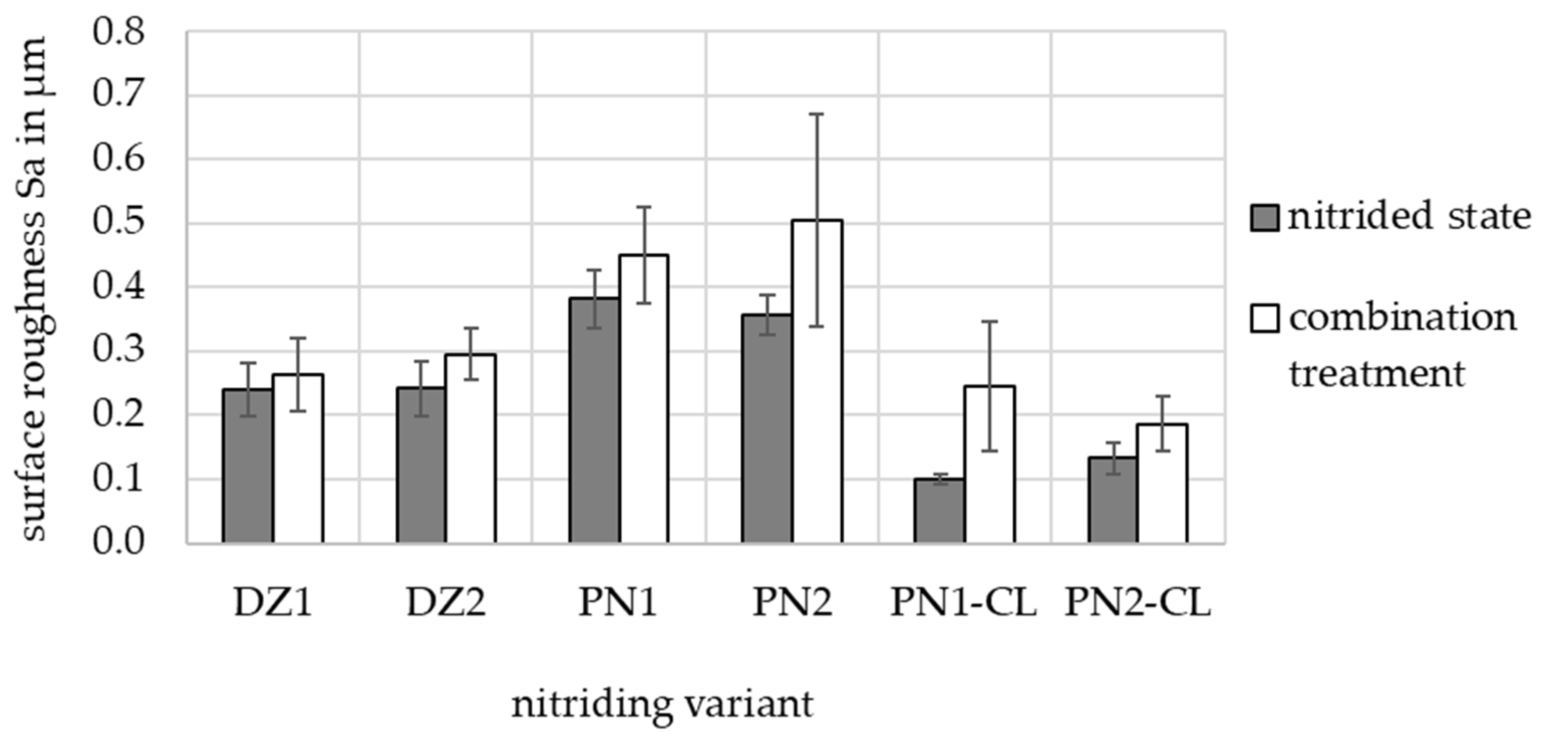
Figure 6.
Hardness in a depth of 10 µm from the surface after nitriding and combination treatment.

Figure 7.
Weight loss depending on the the sliding distance: (a–f) Comparison of the curves for the nitrided-only condition and the combination treatment for the six different nitrided layer variants.
Figure 7.
Weight loss depending on the the sliding distance: (a–f) Comparison of the curves for the nitrided-only condition and the combination treatment for the six different nitrided layer variants.
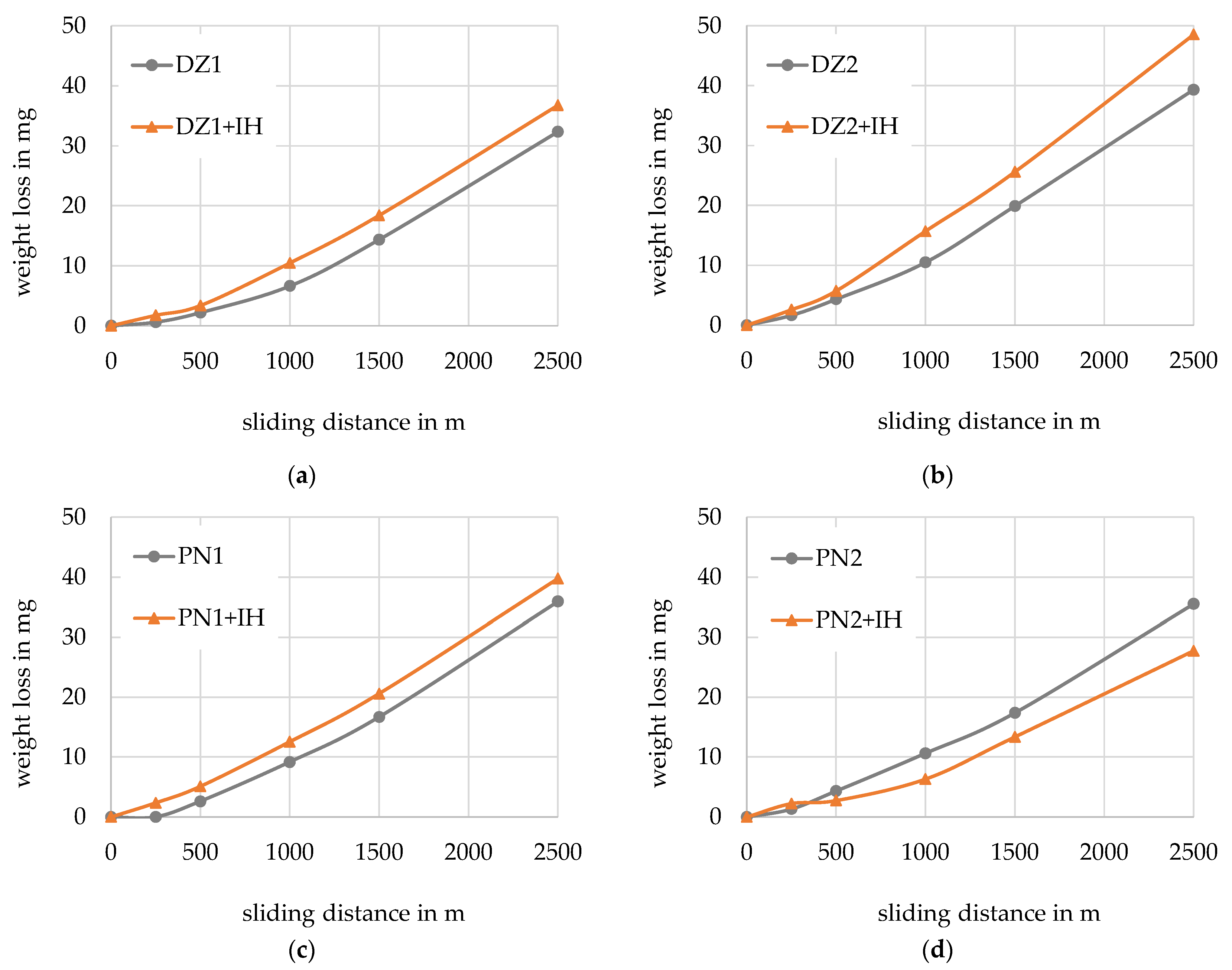
Figure 8.
Wear coefficients of the specimens after 250 m sliding distance (first stage of the wear test).
Figure 8.
Wear coefficients of the specimens after 250 m sliding distance (first stage of the wear test).

Figure 9.
Wear coefficients of the specimens after 2500 m sliding distance (end of wear test).
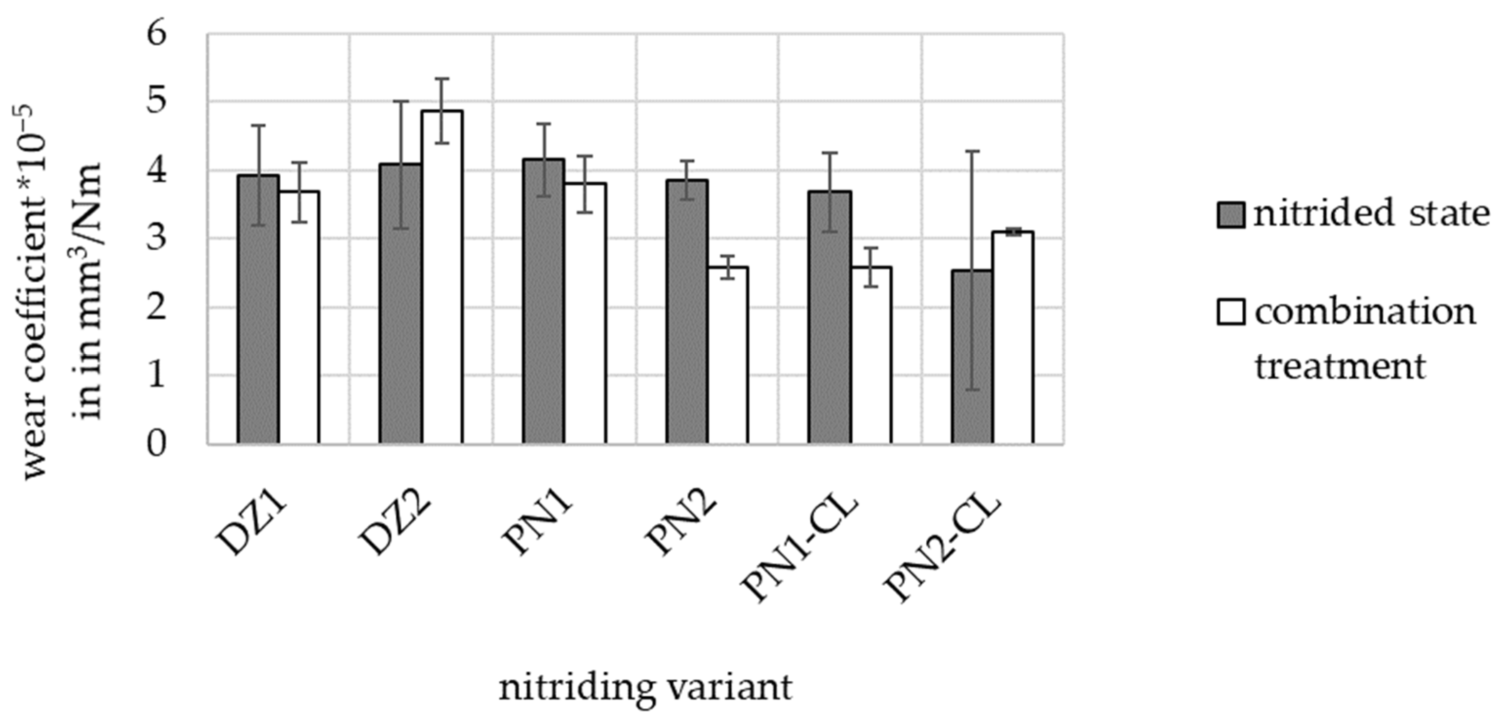
Figure 10.
Profiles of the wear track after a sliding distance of 250 m for the nitrided only conditions (a,b) two different positions on specimen PN1 and (c,d) two different positions on specimen PN2. Note that [1] and [2] are numbers for the optical measurements: value [1] is the depth tmax of the wear track; value [2] is the cross-sectional area AV of the wear track.

Figure 11.
Impact of the amount of retained austenite on the surface hardness.

Table 1.
Chemical composition of the materials under investigation in wt% (measured via optical emission spectroscopy (OES)).
Table 1.
Chemical composition of the materials under investigation in wt% (measured via optical emission spectroscopy (OES)).
| Material | Fe | C | Si | Mn | Cr | Mo | V |
|---|---|---|---|---|---|---|---|
| EN31CrMoV9 | balance | 0.33 | 0.21 | 0.47 | 2.31 | 0.16 | 0.12 |
| ENX153CrMoV12 | balance | 1.51 | 0.33 | 0.37 | 11.59 | 0.92 | 0.80 |
Table 2.
Conditions for gas nitriding (DZ = diffusion zone/technical compound layer free).
| Variant | Temperature in °C | Time in h | Nitriding Potential KN |
|---|---|---|---|
| DZ1 | 500 | 8 | 0.7 |
| DZ2 | 520 | 20 | 0.5 |
Table 3.
Conditions for plasma nitriding with low compound layer thickness (PN = plasma nitriding).
| Variant | Temperature in °C | Time in h | N2:H2 |
|---|---|---|---|
| PN1 | 500 | 8 | 1:4 |
| PN2 | 520 | 20 | 1:5 |
Table 4.
Nitrided variants for the wear testing (CLT = compound layer thickness, NHD = nitriding hardness depth).
Table 4.
Nitrided variants for the wear testing (CLT = compound layer thickness, NHD = nitriding hardness depth).
| Variant | CLT in µm | NHD in mm |
|---|---|---|
| DZ1 | <1 µm | 0.18 |
| DZ2 | <1 µm | 0.33 |
| PN1 | 2.7 | 0.22 |
| PN2 | 2.9 | 0.27 |
| PN1-CL | - | 0.22 |
| PN2-CL | - | 0.27 |
Table 5.
Nitrided and induction hardened variants for the wear testing.
| Variant | SHD in mm | Retained Austenite in ma. % |
|---|---|---|
| DZ1 | 1.02 | 38 |
| DZ2 | 1.05 | 29 |
| PN1 | 1.04 | 35 |
| PN2 | 1.02 | 33 |
| PN1-CL | 1.05 | 10 |
| PN2-CL | 1.03 | 14 |
Table 6.
Weight loss in mg at the beginning of the wear test (after 250 m) and the end of the wear test (after 2500 m) for the nitrided specimens (N) and the nitrided and induction-hardened specimens (N + IH).
Table 6.
Weight loss in mg at the beginning of the wear test (after 250 m) and the end of the wear test (after 2500 m) for the nitrided specimens (N) and the nitrided and induction-hardened specimens (N + IH).
| Variant | 250 m | 2500 m | ||
|---|---|---|---|---|
| N | N + IH | N | N + IH | |
| DZ1 | 0.62 | 1.76 | 32.32 | 36.74 |
| DZ2 | 1.65 | 2.59 | 39.30 | 48.51 |
| PN1 | 0.01 | 2.36 | 35.93 | 39.76 |
| PN2 | 1.33 | 2.25 | 35.52 | 27.74 |
| PN1-CL | 0.50 | 2.60 | 30.51 | 28.10 |
| PN2-CL | 0.24 | 1.19 | 31.70 | 27.39 |
Disclaimer/Publisher’s Note: The statements, opinions and data contained in all publications are solely those of the individual author(s) and contributor(s) and not of MDPI and/or the editor(s). MDPI and/or the editor(s) disclaim responsibility for any injury to people or property resulting from any ideas, methods, instructions or products referred to in the content. |
© 2023 by the authors. Licensee MDPI, Basel, Switzerland. This article is an open access article distributed under the terms and conditions of the Creative Commons Attribution (CC BY) license (https://creativecommons.org/licenses/by/4.0/).
Share and Cite
MDPI and ACS Style
Hoja, S.; Birjandi, B.K.; Hasselbruch, H.; Epp, J. An Investigation into the Wear Behavior of Martensitically Transformed Nitrided Layers. Lubricants 2023, 11, 481. https://doi.org/10.3390/lubricants11110481
AMA Style
Hoja S, Birjandi BK, Hasselbruch H, Epp J. An Investigation into the Wear Behavior of Martensitically Transformed Nitrided Layers. Lubricants. 2023; 11(11):481. https://doi.org/10.3390/lubricants11110481
Chicago/Turabian StyleHoja, Stefanie, Behrad Komeili Birjandi, Henning Hasselbruch, and Jérémy Epp. 2023. "An Investigation into the Wear Behavior of Martensitically Transformed Nitrided Layers" Lubricants 11, no. 11: 481. https://doi.org/10.3390/lubricants11110481
Note that from the first issue of 2016, this journal uses article numbers instead of page numbers. See further details here.