1. Introduction
The piston cylinder unit is the central part of an internal combustion engine and has significant influence on the mechanical and thermodynamic losses as well as the pollutant emissions resulting from the oil [
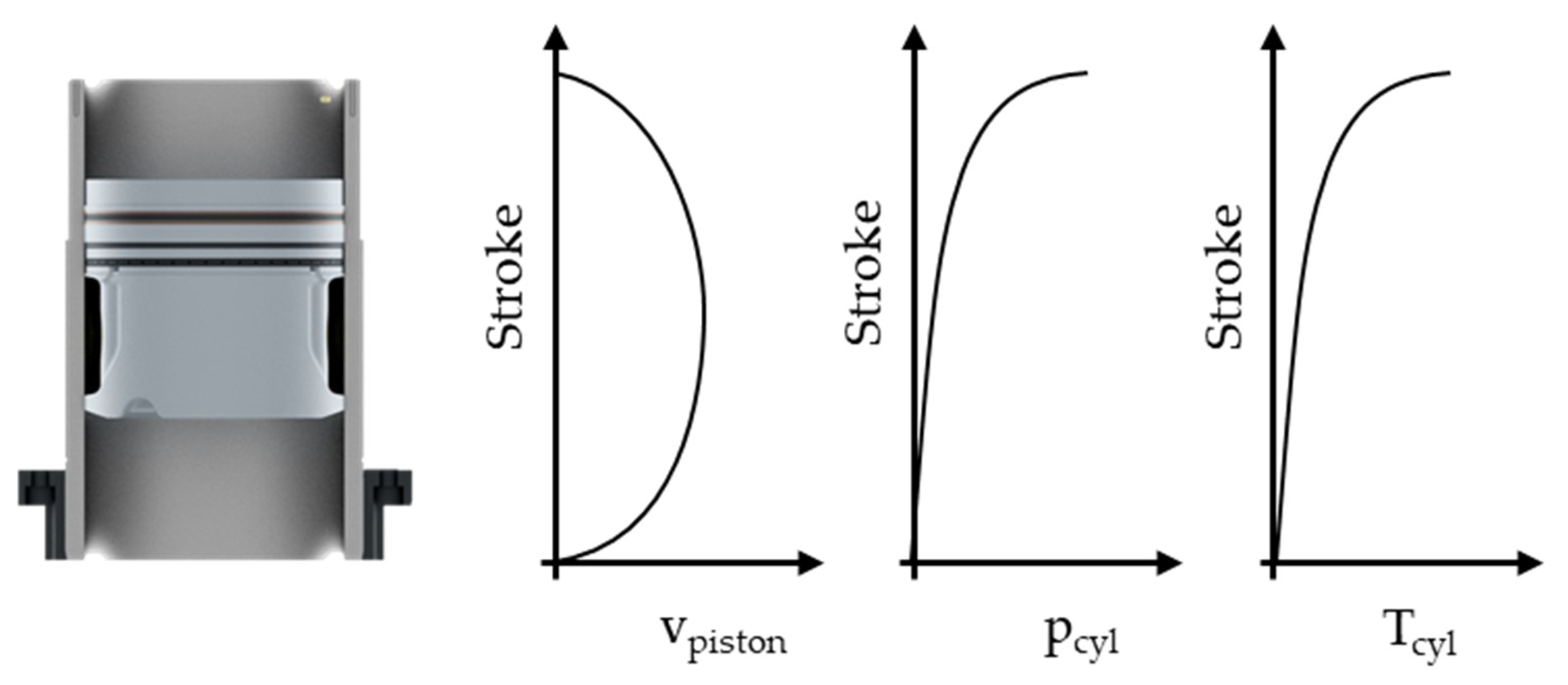
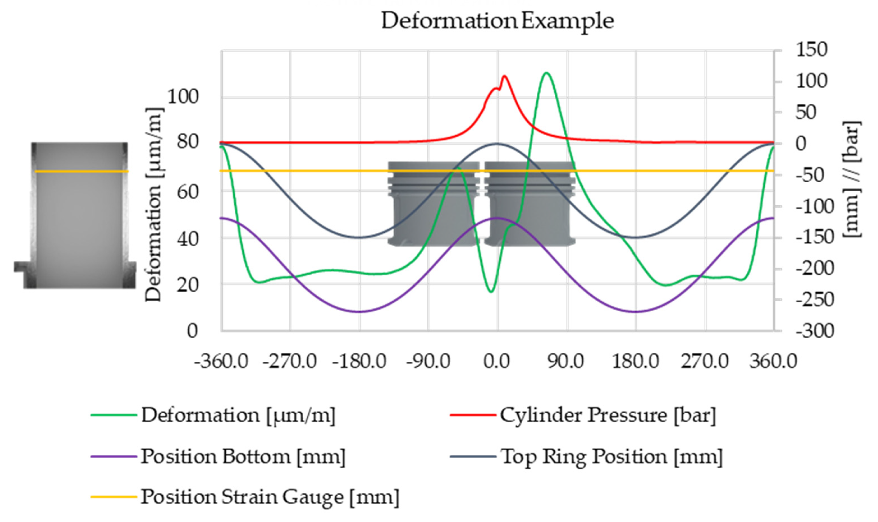
1]. The piston assembly consists of the piston, piston rings and the cylinder liner. The piston, which follows a sinusoidal forced motion from the crankshaft, carries the piston rings in their respective ring grooves. The piston rings are responsible for sealing the combustion chamber from the crankcase and are in tribological contact with the cylinder liner. Due to additional motion forms (hereinafter referred to as piston secondary motion), the piston is also in direct frictional contact with the cylinder liner. The components of the piston assembly form a tribological multibody system; each component forms a tribological system. Due to the different boundary conditions of each system, varying manifestations of friction forces result. In the following discussion, the individual components are reduced to a collaborative tribological system, allowing a holistic consideration of the piston assembly, whereby the resulting friction is a combination of the respective frictional states. The piston speed (v
Piston), cylinder pressure (p
cyl) and the corresponding temperature (T
cyl) are the essential variables depending on the crankshaft angle during the stroke.
Figure 1 exemplifies the variation in the boundary conditions during one working cycle and illustrates the complexity of the tribological investigation of the piston group.
Due to inhomogeneities resulting from the overall engine construction and uneven heat sources and sinks, deformations of the cylinder liner occur. The varying temperature distribution results, on the one hand, from heat flows from combustion combined with the cycle-dependent cooling performance of the coolant mass flow and, on the other hand, from mechanical loads arising from combustion pressure and assembly [
2,
3,
4]. However, some of these effects can be partially compensated during the production of the cylinder liner using honing processes with a pretensioned liner.
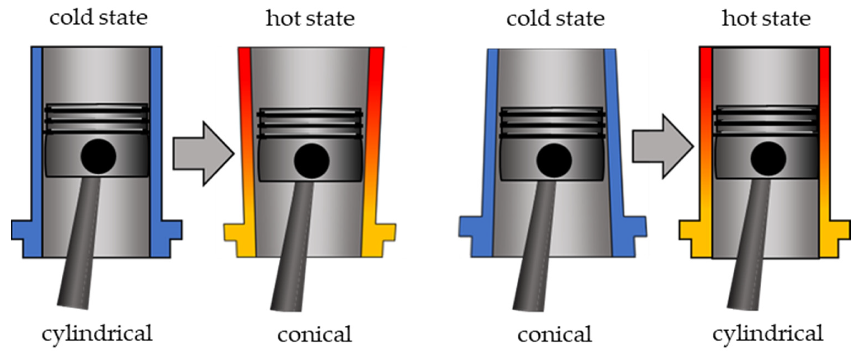
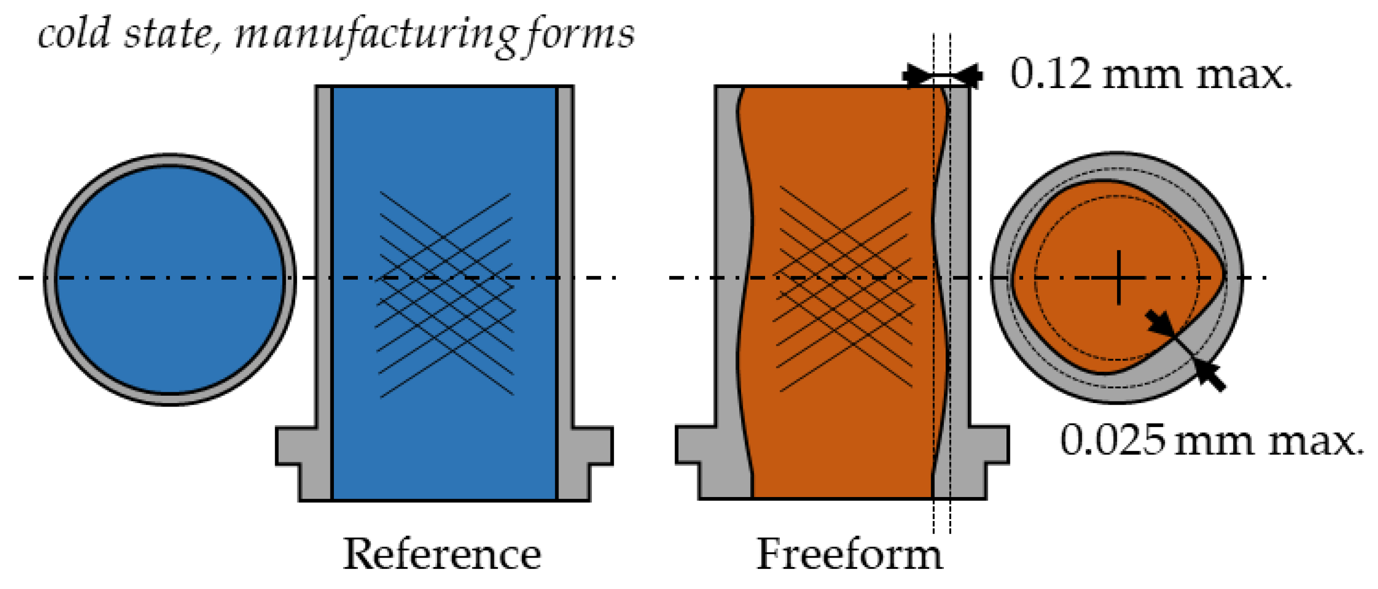
Figure 2 illustrates on the left a schematic deformation of a cylinder liner in the hot state. The conical-shaped deformation causes a narrowing of the lubrication gap between the cylinder liner and the piston skirt in the region of the Bottom Dead Center (BDC). An advance approach regards this deformation with an inverse conical shape in the cold state, shown on the right in
Figure 2. The advanced manufacturing process required for this is already partly applied in mass production [
5].
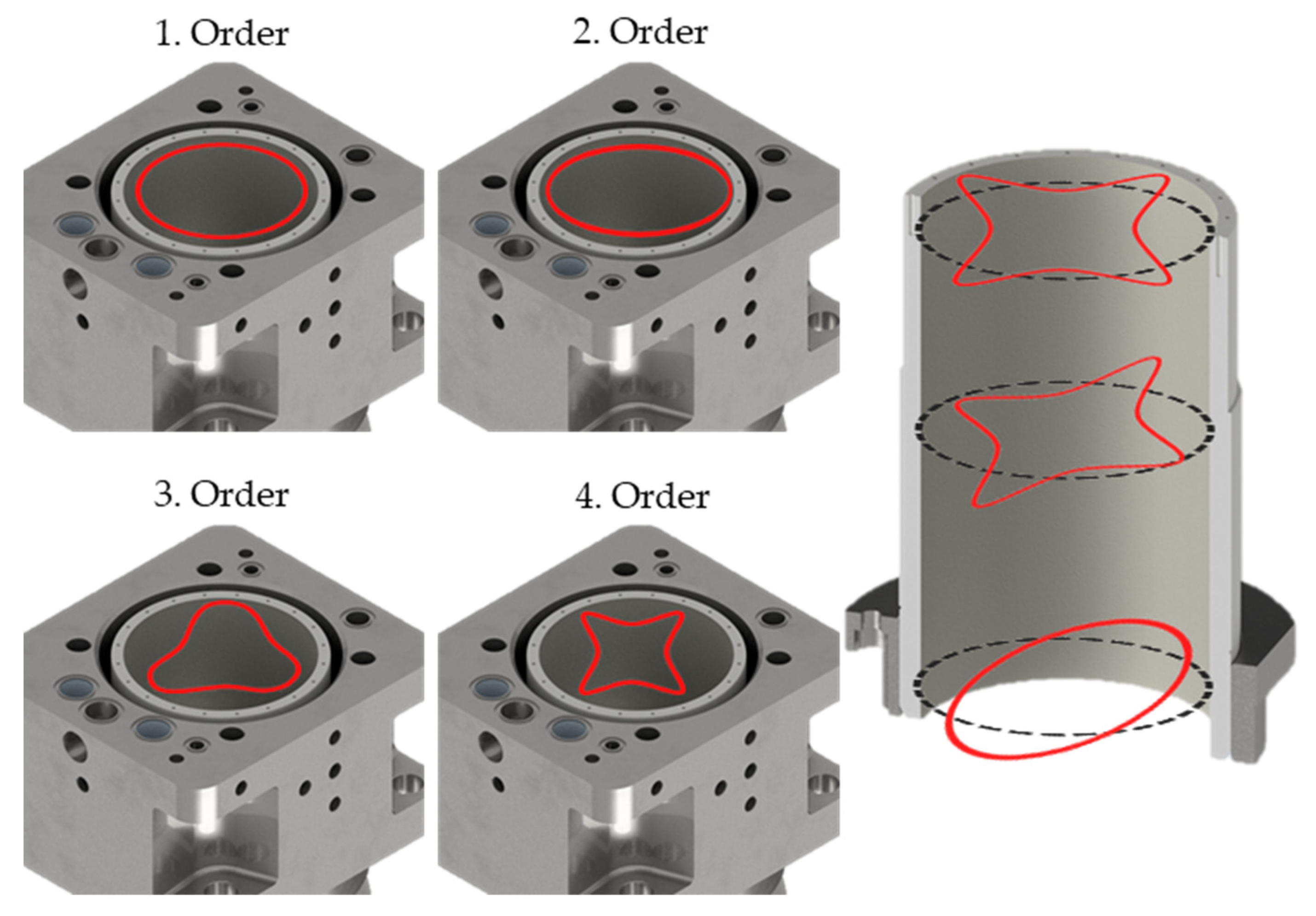
However, due to the varying wall thickness of the surrounding components and the resulting circumferentially changing heat transfer, different radial deformation forms are to be expected in the piston liner cross-section on each height (see
Figure 3), which can be approximated by Fourier series [
4]. During the operation of the internal combustion engine, uneven contact regions occur between the piston rings and the cylinder liner: this particularly affects the compression rings with tribological contact to the cylinder liner. In the presence of large clearances or lower-contact forces of the rings, leakages occur, negatively impacting the operation of the combustion chamber. Additionally, this can lead to oil entry into the combustion chamber (reverse blow-by) and it is one reason for higher emissions. Conversely, a tighter sealing results in a higher friction force [
5,
6,
7,
8,
9,
10,
11,
12,
13,
14,
15,
16].
As part of the “Powertrain 2025” project [
17], cylinder liners are being developed to reduce energy consumption in both manufacturing and operational phases. Therefore, the geometry of the liner has been modified to minimize friction and leakage losses. Reduced friction force directly decreases the mechanical losses and is one part of internal combustion engine investigations for higher efficiencies and lower CO
2 emissions. The deformation of the cylinder liner from the Floating-Liner engine at the Institute for Technical Combustion (ITV) of Leibniz University Hannover is determined by simulations [
17,
18], based on finite element methods described in [
19]. For this simulation, the thermal and mechanical load for one operation point (1300 rpm and 15.5 bar indicated mean effective pressure) is used. Based on this investigation, a free-form cylinder liner has been designed aiming to achieve a straight, cylindrical liner under warm-motored conditions. Subsequently, the liner was manufactured at the Institute of Production Engineering and Machine Tools (IFW) of Leibniz University Hannover with a novel milling process [
17,
20]. The aim of the study is to compare experimentally the friction forces for a reference liner, produced with a cylindrical form, and a liner produced with such a novel free-form honed liner design, which in the hot operation state is approximately cylindrical; also, the blow-by losses are determined [
21,
22,
23,
24]. In the following, at first the experimental setup is described with the test bench of the Floating-Liner single-cylinder engine. Then, more details of the two investigated liners and the investigated map of operation points are described, including an investigation of the experimentally determined deformation of the cylinder liner using strain gauges. Measurements of the two liners are described in a step-wise procedure: friction measurements with a disassembled cylinder head and motored engine for a first tribological characterization, and then friction measurements with an assembled cylinder head to investigate the influence of the combustion chamber pressure for motored and fired operations. In the
Section 4, these data are analyzed, allowing a detailed analysis of the geometry influence on the friction contribution in the different process steps of the moving piston. Here, and in the
Section 5, it will be discussed whether the following research questions can be answered: if a free-form cylinder liner design can reduce the friction from the piston group also in a broad range of operation conditions and if also the blow-by losses can be influenced.
3. Measurement Results
In the following, the friction force profiles of the cylinder liner variations are initially examined for measurements without pressure in the combustion chamber, followed by the corresponding profiles with the influence of cylinder pressure. For a detailed presentation of crank-angle resolved measured friction forces, only the operating points at n = 600 rpm are discussed here, as here a minimal influence from piston secondary movements and other disturbances is given. The profiles are derived from the averaged friction forces over 200 working cycles.
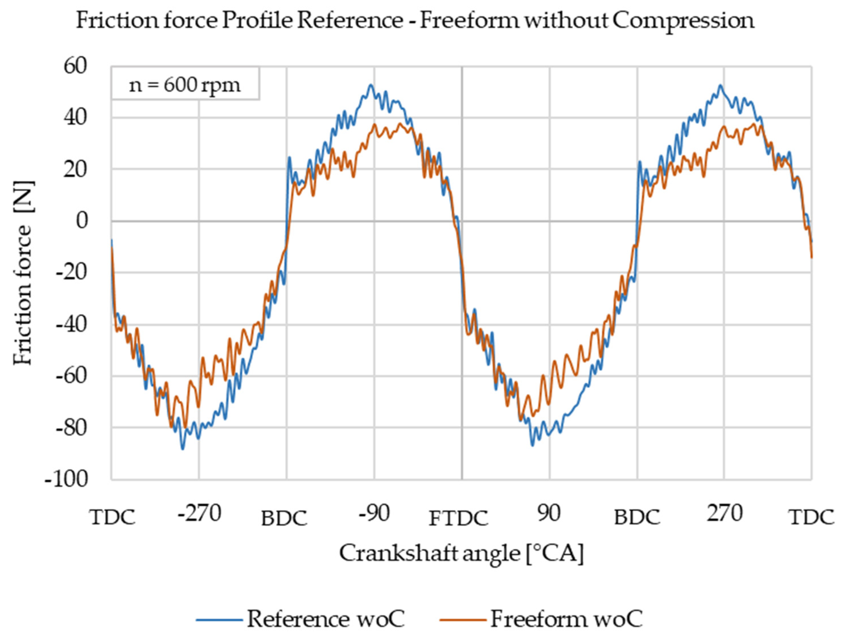
Figure 8 depicts the friction force profile of the cylinder liner during a drag operation without compression, recorded by the two force sensors (the sum of the signals is shown).
The measured friction force is plotted on the ordinate of the diagram, while the crankshaft angle is represented on the abscissa. The friction force is either positive when the piston movement is upwards directed or negative for the downwards movement. The friction value depends on the tribological process with fast jumps near the reversal points of the piston movement (dead center) and the piston movement speed in the hydrodynamic friction range with curved parts between the reversal points. Some oscillations are overlapping the force signal coming from vibration of the Floating-Liner system or the piston rings. The friction force of the reference liner is nearly symmetrically curved, while the free-form honed liner shows mostly lower friction, especially in the lower part of the liner, where the shape in this cold state is wider (see
Figure 6). The reference liner exhibits a pronounced friction force peak at the BDC (Bottom Dead Center). Analysis of other operating points without compression reveals that the free-form honed cylinder liner causes lower friction force across the entire speed range.
Figure 9 shows the friction force profile with the cylinder head mounted, where at the FTDC (Fired Top Dead Center) the cylinder pressure rises to about 80 bar. Note that this is still an example without combustion (IMEP = −2 bar), so that the temperature of the liner is still rather low. Near the FTDC, the measured friction forces are significantly enhanced, reaching values of up to 400 N, compared to the much-lower forces for the cases without compression. This is expected from the mechanical influence of the cylinder pressure.
The curved profile between the reversal points is also observed in the measurements with compression pressure. The lower friction force level in the hydrodynamic area of the free-form honed liner is not clearly pronounced under the influence of cylinder pressure. Contrary to the operation without cylinder pressure, the friction force at the FTDC is at a higher level for the reference liner. The free-form honed liner exhibits a decreasing behavior in the range of −30 °CA to 30 °CA. The friction work of the piston group is determined by an integration of the measured friction force (
) and the speed of the piston (
) over the crank-angle
resolved operation cycle (OC). The friction mean effective pressure of the piston (FMEP
P) results from the engine-displacement-related friction work.
Here,
=
r/
l is the ratio of the crank radius to the length of the rod, and
is the displacement volume of the cylinder. The piston velocity is calculated according to text books, e.g., [
1,
33,
34].
Near the fired top dead center (FTDC), the friction force reaches its maximum; therefore, the value ∆FFTDC is also evaluated. The friction mean effective pressure of the piston (FMEPP) is a part of the total engine friction, commonly described by the mean effective pressure (FMEP) of the whole engine. The values FMEPP and the effective engine power Pe serve as references for the friction force measurements. Additionally, blow-by flow and the maximum cylinder pressure (pmax) are considered to assess the sealing of the combustion chamber against the crankcase.
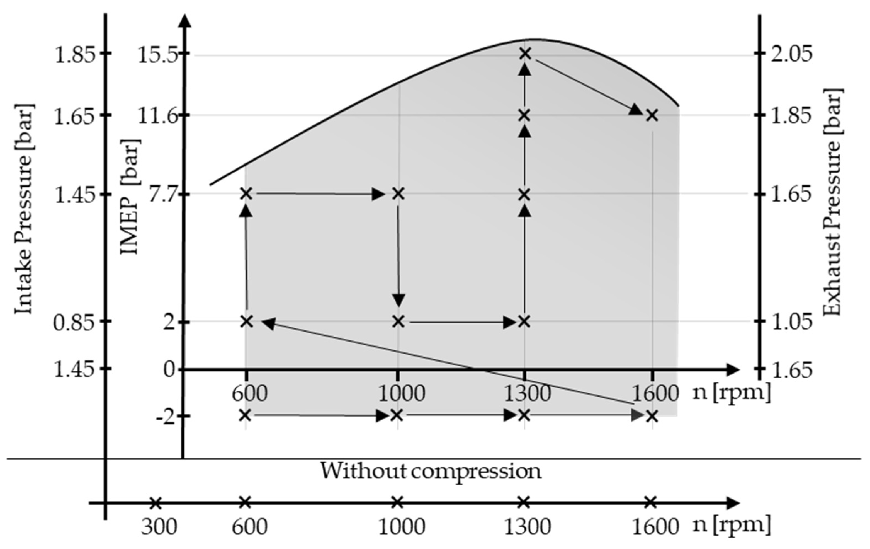
The following measurements are presented in the engine map, where the engine speed is plotted on the abscissa and the indicated mean effective pressure (IMEP) is shown on the ordinate. This representation allows the investigation of load and speed dependencies of the measurement quantities.
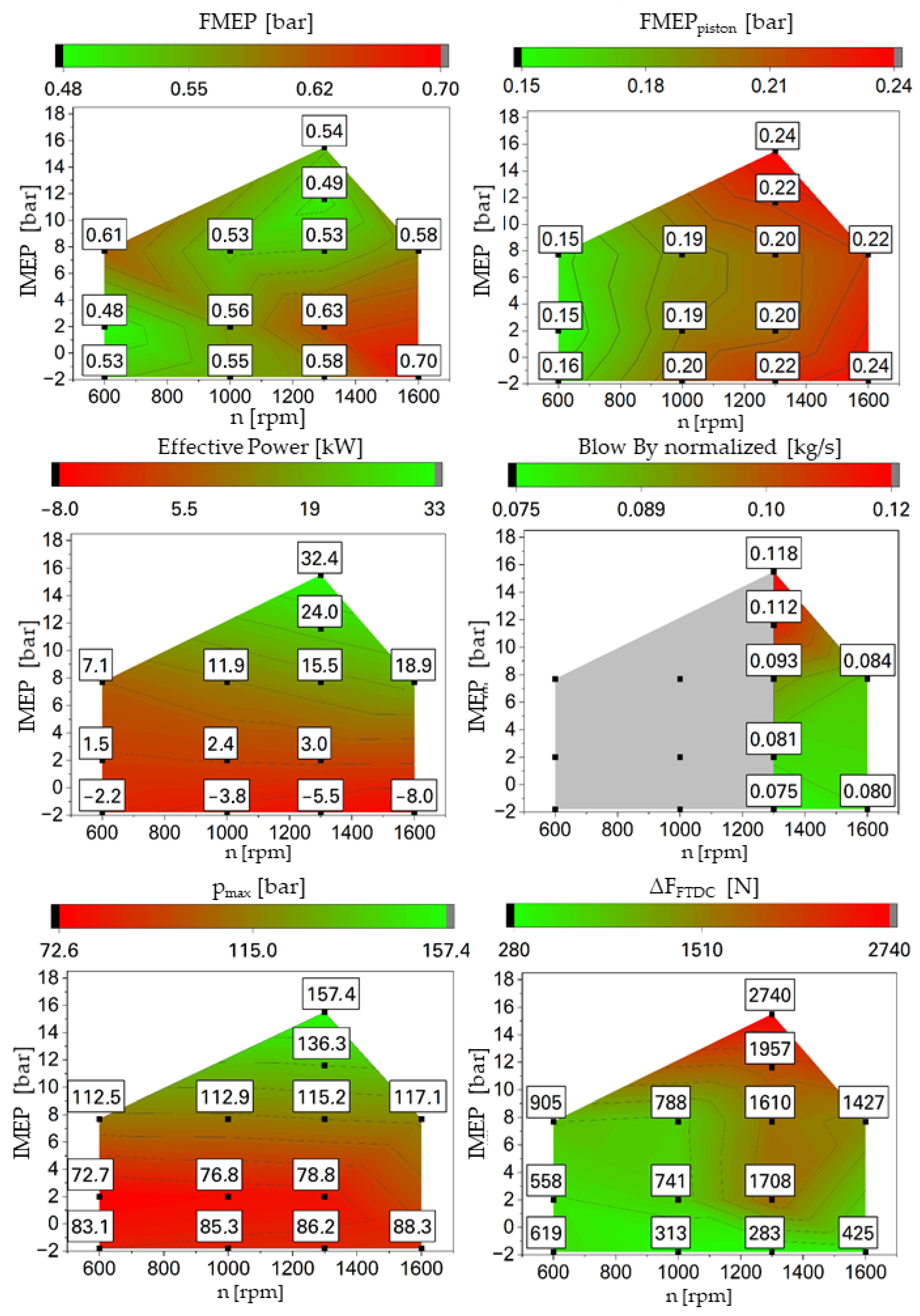
Figure 10 shows the measurement results of the cylinder liner with free-form honing. The total engine friction (friction mean effective pressure, FMEP) is determined from the difference between the measured break mean effective pressure, BMEP, and the measured indicated mean effective pressure, IMEP. It increases with higher engine speed for lower and medium load. For higher load and speeds of 1000 rpm and 1300 rpm, a significant reduction in total engine friction is observed with increasing IMEP. The FMEP
P, however, being determined from the measured forces of the Floating-Liner, exhibits a clear speed-dependent behavior, while only minor variations are found for varied load. The blow-by measurement is suitable only for higher speeds due to the measurement method. As a result, only a comparison of operating points around 1300 rpm and 1600 rpm is possible. For better characterizations of the blow-by, the measured values are normalized to the intake mass flow. The blow-by increases with rising IMEP but shows only a weak dependency on engine speed. The cylinder peak pressure shows a behavior equivalent to effective power (Pe). The friction force height at the fired top dead center ∆F
FTDC decreases with increasing speed during motored operation. For fired operating points, a reversed behavior is noticeable, with an alternating pattern observed at an IMEP of 7.7 bar. In terms of increasing IMEP, the ∆F
FTDC value rises. The largest amplitude is observed at a speed of 1300 rpm and an IMEP of 15.5 bar.
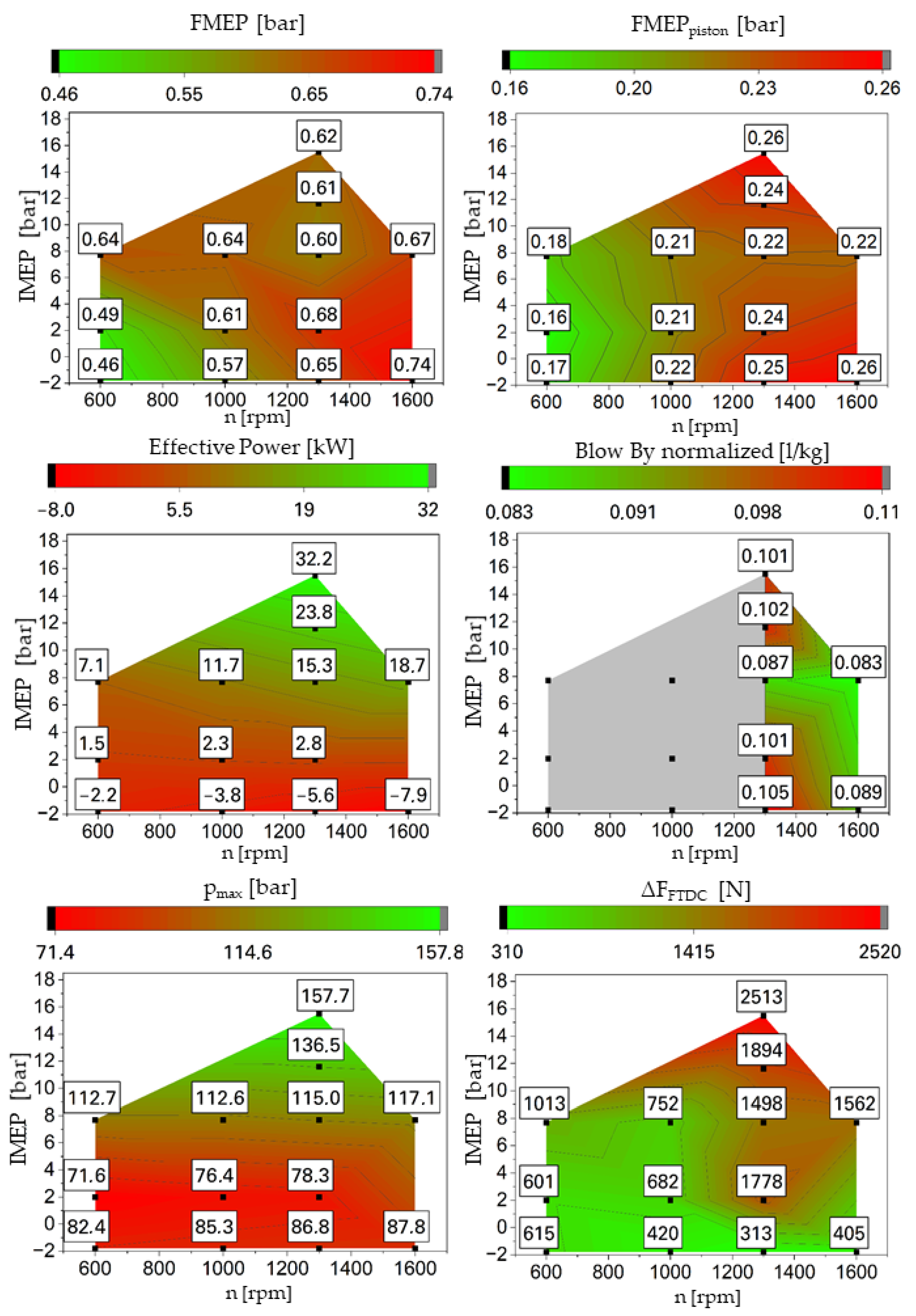
The measurement results for the reference liner are shown in
Figure 11. The friction contribution FMEP reaches its minimum at the lowest load points, increasing at higher speeds and IMEP. The drag operation points show increased friction for the piston group compared to points with identical speeds but at higher indicated mean pressures. The friction of the piston group also increases with higher speeds. The effective power, maximum cylinder pressure and force jump at the FTDC exhibit similar trends to the cylinder liner with free-form honing. The blow-by reaches its minimum at an engine speed of n = 1600 rpm. At an engine speed of n = 1300 rpm, a swelling behavior of blow-by is noticeable, while a reduction in leakage in the middle load range is distinguishable.
4. Discussion
The following analysis will delve into the previously presented results, specifically examining the impact of the shape of the cylinder liner and investigating associated dependencies.
4.1. Influence Analysis through Investigations without Compression
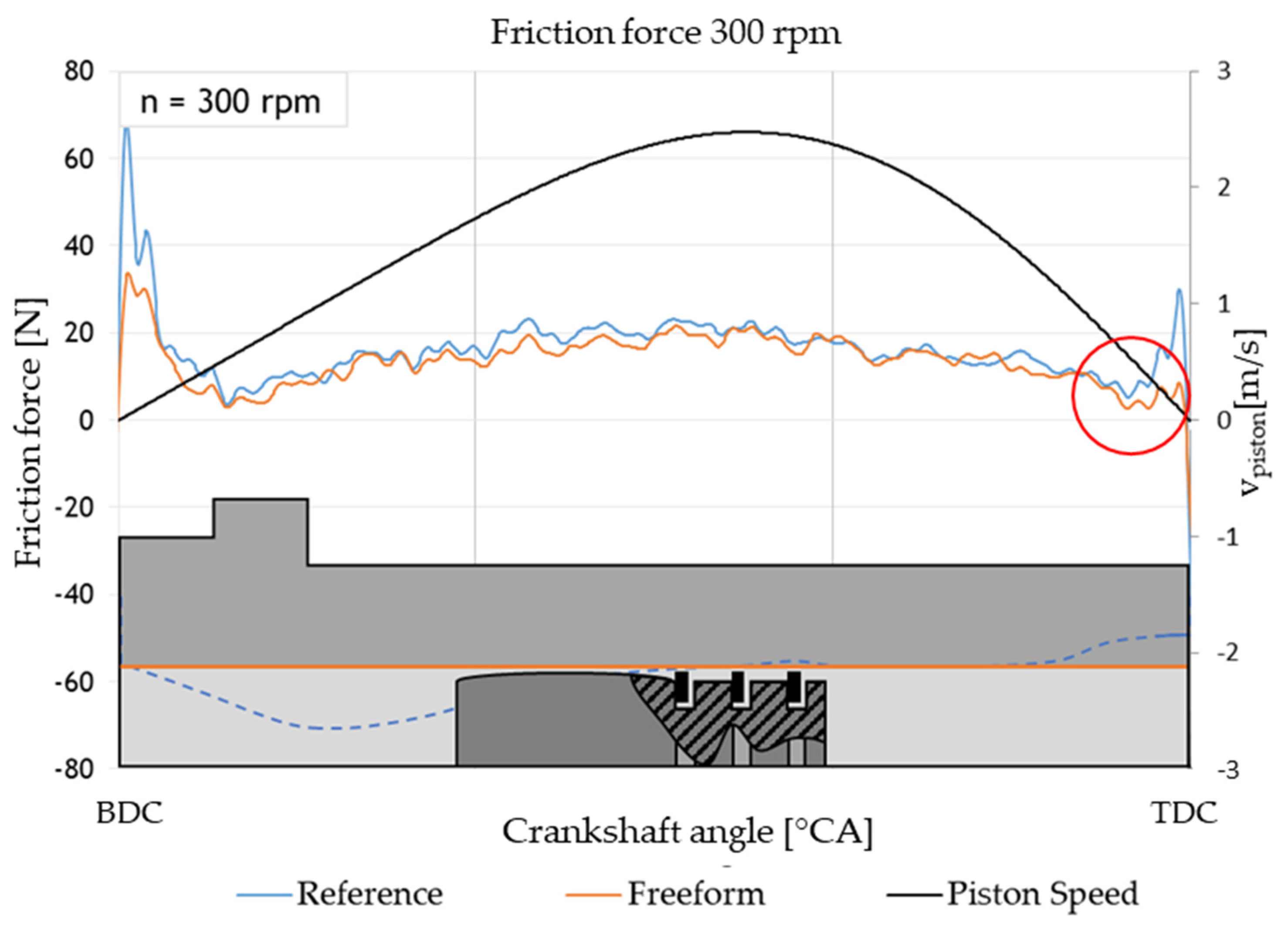
Figure 12 exemplifies the friction force profile for an upward stroke (−180 °CA–0 °CA) at 300 rpm without compression combined with a draft of the sectioned cylinder liner to depict the bore diameter in the warm operation state (only thermal deformation due to operation without compression).
The color codes for the sectioned cylinder liner correspond to the investigated variations in the cylinder liners and the friction force profiles. This representation aims to elucidate the influence of the varying bore diameters on the resulting friction force. In the hydrodynamic-predominated area, the free-formed honed liner shows slight advantages along the whole stroke. This is caused by the better alignment of the liner and the piston shaft over the height of the liner. Due to a larger lubrication gap, the shear stress is reduced. Towards the reversal points, the friction decreases for both liners due to slower piston speed. The minimum friction force can be associated with the Stribeck point, where the sum of hydrodynamic friction and boundary friction is minimal. For the reference liner, the Stribeck point towards the TDC is associated with a crankshaft angle of φ ≈ −10 °CA. For the free-form honed liner, a Stribeck point with a lower relative velocity is evident (marked detail), resulting in an enlarged hydrodynamic section and a smaller wear-related boundary friction part. At the reversal points, the better circular shape of the free-form honed liner reduces the contact pressure of ring pretension and leads to less boundary friction. At this operation point, the circular advantage is more pronounced than the deformation over the height; otherwise, the contrary clearances in the BDC and the TDC would create contrary friction results. For this operation point, the thermal deformation of the liner is only influenced by the supply medium temperature. In the design of the free-form liner, however, combustion temperature and pressure of the operation point at 15.5 bar IMEP and 1300 rpm have been considered, leading to the assumption that the deformation of both liners over the height is rather similar for the shown operation point. The circular deformation, however, is compensated and shows the measured friction advantages. Comparing the BDC with the TDC, the friction force amplitude of both cylinder liner variants is greater when the piston is at rest at the BDC. This difference can be attributed to the asymmetric convexity of the compression rings and the piston, causing the behavior of the existing lubricant in the lubrication gap to vary with changes in relative velocity. The lower oil volume during the upward stroke must be considered, since only the non-scraped oil from the previous downward movement is available for lubrication. Furthermore, it is possible that the deformation in each region is different. This is indicated by the different advantages of the free-form liner due to its circular deformation compensation.
4.2. Influence Analysis through Investigations with Compression
To investigate friction forces under engine-operating conditions, the cylinder liners are compared for varying load points across speed and indicated mean pressure (IMEP) in the following exposition.
For exemplary representation of the friction force profiles,
Figure 13 depicts the friction forces at the lowest speed, n = 600 rpm, without combustion. This minimizes the impact of oscillations on the overall trend in the measured data. This representation allows for a cycle-dependent analysis of friction forces. The friction force profiles over the 200 averaged working cycles show minimal macroscopic differences between the examined cylinder liners for the parts with higher velocity between the turning points. The effects elucidated in
Section 4.1 for hydrodynamic friction between the reversal points are not continuously evident along the stroke. In the region near the TDC, significant increases in friction force are observed due to the compression cycle. The free-form liner shows clearly reduced friction from about −30 °CA on, as it approaches the TDC. The improved roundness of the free form ensures an enlargement of the lubricating film-building surfaces of the piston rings, expanding the hydrodynamic region of friction. Despite the acting combustion chamber pressure, the collective load can be influenced in such a way that hydrodynamic friction persists at low relative velocities. Additionally, the force jump at the TDC for the free-form honed liner is smaller than that of the reference. This may result from the diminishing clearance and the consequent expansion of the hydrodynamic friction area at lower relative speeds, leading to a reduction in solid friction. This could additionally be supported by minimizing piston tilting, by a better guidance, leading to a substantial increase in the effective contact area and a decrease in contact pressure.
4.2.1. Analysis of Piston Group Friction
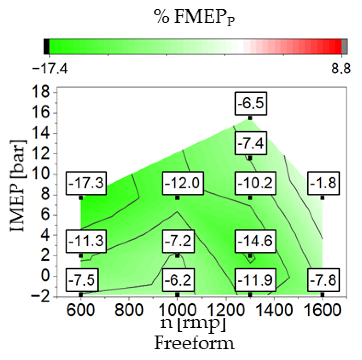
To analyze the friction reductions across the entire operating map, the percentage changes in piston group friction are depicted in
Figure 14. The reference liner serves as the baseline for comparison.
Figure 14 shows significant advantages for the free-form liner, particularly at low speeds and high indicated mean effective pressures. The most substantial reduction of 17.3% for the free-form honed cylinder liner occurs at a speed of n = 600 rpm and an indicated mean effective pressure of IMEP = 7.7 bar. The comparison shows, further, that the free-form variant induces reductions in piston group friction over the entire operating map. Here, the influence of the basic design idea is clearly visible. According to that design, the operated liner being heated from the combustion process has a form which is obviously nearer to a cylindrical shape, thus reducing the averaged friction. The presented results demonstrate that the designed free-form honed cylinder liner achieves significant reductions in the friction for the piston group of up to 17.3%, with an average reduction of 9.3% across the investigated operating map. This corresponds to an averaged power advantage of 0.103 kW.
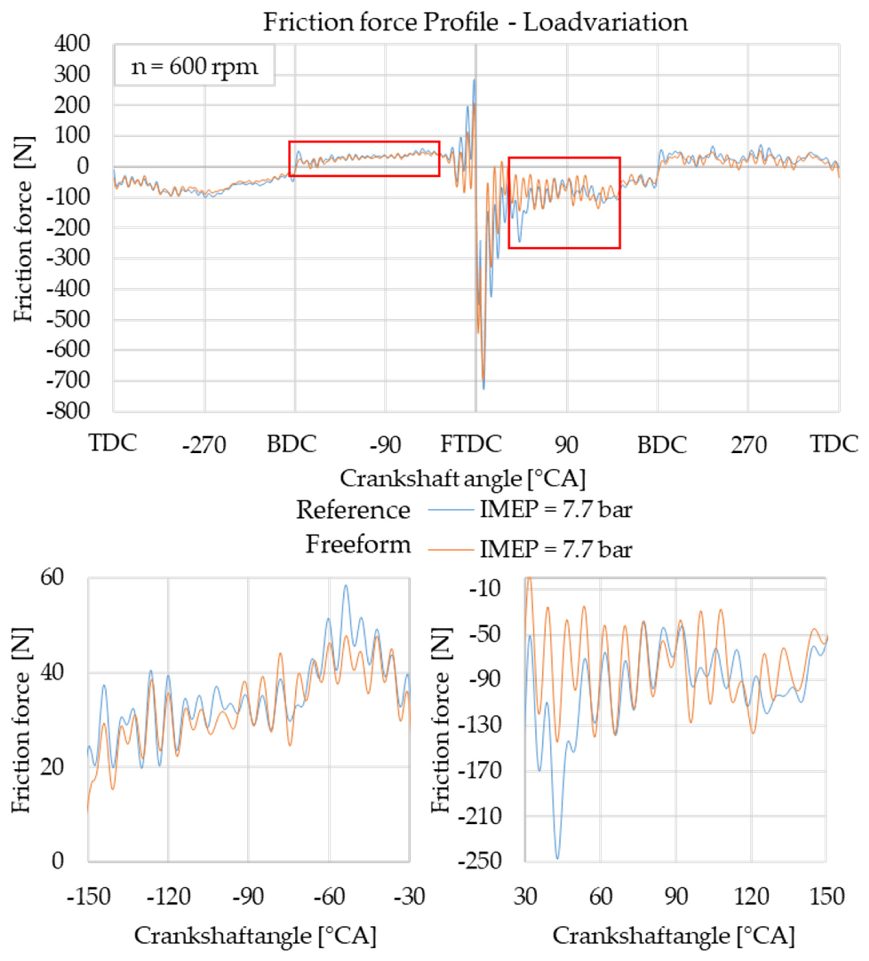
In order to analyze the difference in the friction forces in more detail, the direct visual comparison of the measured friction force is less easy than for the cases without combustion, as the force signal is biased by increasing oscillations. They have their source, on the one hand, from excitations of the Floating-Liner system, as the liner is partly movable in its upper part and forms its own dynamical system. On the other hand, the piston rings have their own dynamics, inducing some oscillations on the observed pressure signal. For the average friction, as has been evaluated before, these oscillations are suppressed due to the averaging over time. With some care, some observations can be made for the detailed friction process as a function of crankshaft angle.
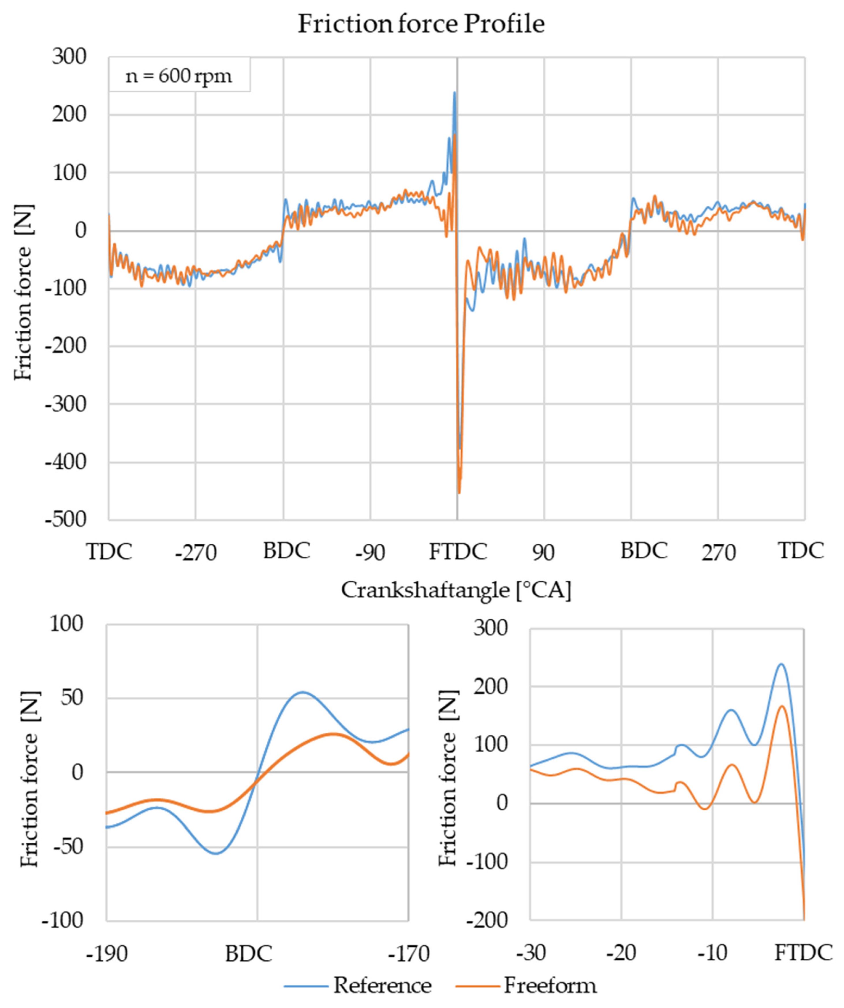
Figure 15 depicts a load of IMEP = 7.7 bar at a speed of n = 600 rpm for both the reference and the free-form honed cylinder liner as a function of the crankshaft angle. Due to the high piston speed in the mid-stroke range, and the existing hydrodynamic friction, a significant impact is observed. Additional disturbances from the combustion pressure occur during the combustion cycle, aligning in frequency, but complicating graphical interpretation. For a more detailed analysis, these areas are depicted separately for both the compression and combustion stroke. In this examination, a noticeable reduction in frictional force is evident in the higher combustion chamber pressures, which, due to the substantial volume change per crankshaft angle, exerts a significant influence on the FMEP
P. Additionally, due to the adapted shape of the free-form honing, a further reduction in friction is distinctly observed in the high combustion chamber pressure range. This relation results in reductions in frictional force of 13.1% for the compression stroke and 21.8% for the combustion stroke. The additional reduction for the first and the fourth stroke in the hydrodynamic friction range results in an overall reduction of the FMEP
P = 17.3% for the depicted load point IMEP = 7.7 bar.
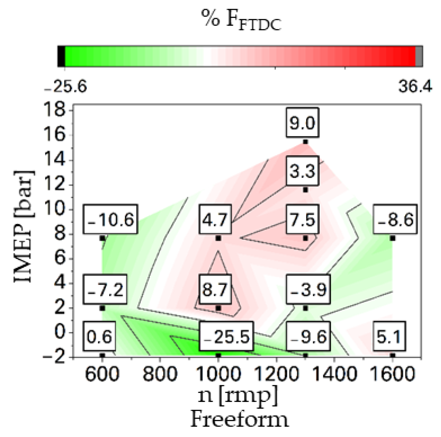
4.2.2. Analysis of the Peak Friction Force at the Fired Top Dead Center
To examine the peak friction forces at the fired top dead center (FTDC), the percentage changes are plotted in
Figure 16. Additionally, the value of the friction force peaks serves as an indicator for wear characteristics. For the free-form honing, it becomes evident that reductions in the friction force jump can be achieved in the lower and upper speed range of the operating map. However, increases in the peak friction force are observed in the middle and upper range of the indicated mean pressure. This behavior suggests that the designed shape of the cylinder liner or the resulting shape from the manufacturing process is not optimally adapted to the thermal influences in this load range.
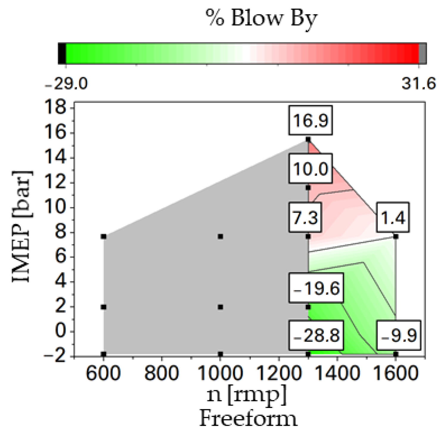
4.2.3. Analysis of Blow-By
Figure 17 presents the measured blow-by values for evaluating the sealing behavior of the piston group, again as the relative change in the free-formed liner in comparison to the reference liner. Due to the utilized measurement system, as indicated before and described in [
11], only speeds n > 1200 rpm can be considered. Generally, the blow-by losses increase with higher indicated mean effective pressure, as the compression and combustion pressure increases. For the investigated free-form honed liner the increase in blow-by at high IMEP is even stronger that for the reference form, as can be seen in the relative change in the blow-by in
Figure 17. For the highest operating point, the blow-by increases up to 16.9% of the reference. For lower IMEP, the free-form honed liner shows much smaller blow-by with measured reductions up to −28.8%. The measurements of the blow-by show an operating-point-dependent behavior, indicating a suboptimal design of the free-formed liner.


