Abstract
The complex sliding behavior inside ball bearings seriously affects the mechanical system’s performance. Current dynamic models for predicting this behavior suffer from poor generality and convergence. To address this issue, different interactions between the ball and raceway are proposed in this paper to simulate the dynamic behavior by analyzing the bearing assemblies’ motion features under typical operating conditions. The number of variables and equations to be solved is determined adaptively according to the bearing load characteristics, thus improving the efficiency and convergence of the model solution. The good agreement between simulation results and experimental test results validates the reliability of the model. The sliding behavior at the ball/raceway interface under different conditions is further investigated. The results show that the heavy external loads can avoid severe sliding at the interface but shorten the bearing’s fatigue. When the bearing is subjected to combined load conditions, the increased radial force inhibits bearing sliding while increasing the non-uniformity of the sliding velocity distribution.
1. Introduction
Ball bearings are widely used in rotating machinery systems due to their ability to withstand various types of loads. Because of the complex motion of the bearing components, the sliding behavior at the ball/raceway interface is inevitable. Once this behavior becomes very severe, the surface wear of the balls or raceways will be accelerated, shortening bearing life and even causing catastrophic accidents in machine systems [1,2,3,4]. Furthermore, severe sliding inside the bearing generates a lot of heat, which drives the bearing into thermal instability and thus increases the wear of the interface [5,6,7]. As a result, the sliding behavior inside the ball bearing is required to be investigated to guide structural design and improvement of the systems.
Since current experimental methods cannot accurately monitor the dynamic behavior inside bearings, numerical simulation models have become a common approach for studying bearing sliding. The quasi-static model was first used by some scholars to conduct the sliding investigation. Based on this model, Xu [8] investigated the critical load of the bearing without integral sliding under pure axial force conditions. Following this, the sliding behavior at the ball/raceway interface under combined axial and radial loads was investigated by Liao [9,10] using the Hirano criterion [11]. In addition, Tong [12] improved the quasi-static model and further examined the effect of load, rotational speed, and mounting errors on the bearing sliding at the contact interface. Regrettably, the transient behavior of the bearing components cannot be simulated by the quasi-static model because many factors, including covering lubricants and the cage dynamic effect, are ignored. In particular, the action of the lubricant has a strong influence on the dynamic performance of the ball at the interface [13]. Therefore, the bearing dynamic model, being the most complete model available [14], has become one of the most effective means to investigate the sliding behavior inside bearings. Meeks [15,16] first established a new bearing dynamic model by extending Jones’s quasi-static model [17,18]. Although this model can only investigate the cage’s dynamic behavior, it does provide ideas for further work. Subsequently, Jain [19] used the load distribution obtained from a simplified quasi-static model, in conjunction with elastic fluid theory, to construct differential equations for the ball’s rotational motion. The angular velocity features of the ball under a single operating condition were investigated by him. On this basis, Han [20,21] examined the sliding behavior at the ball/raceway interface under combined axial and radial load by considering the ball’s gyroscopic moment. However, these above models used nonlinear equations rather than differential equations to constrain the ball’s radial motion, suppressing the ball’s high-frequency vibration and failing to accurately predict the dynamic behavior inside the bearing [22]. To address these deficiencies, Wang [23,24,25,26] employed six differential equations to completely determine the ball’s complex motion and further developed a new bearing dynamic model. The sliding behavior at the contact interface under two typical operating conditions (pure axial force and combined axial and radial force) was investigated. Unfortunately, limited by the algorithm for solving the differential equations, the solution of this model depended heavily on the accuracy of the initial values [27]. To precisely simulate the dynamic behavior of the ball bearing components, these models must be solved in turn: the static model, the quasi-static model, and the dynamic model. The static model results are used as initial values for the quasi-static model interactions, and then the quasi-static model results are further used as initial values for the differential equations in the dynamic model. However, when these models are used to simulate the dynamic performance under various operating conditions, their solution efficiency and convergence can vary significantly [28]. The high-frequency dynamic behavior at the ball/raceway interface, in particular, can pose a significant challenge to model convergence for predicting the bearing’s performance under certain harsh operating conditions. In addition, some scholars have noticed that the tribological behavior inside the contact interface has a non-negligible effect on the bearing’s dynamic performance [29,30,31].
In summary, there is a lack of a general bearing dynamic model with efficient solutions and strong convergence under various operating conditions. Additionally, the sliding behavior under typical conditions has not been sufficiently investigated. To this end, different interactions between the ball and raceway are constructed for various operating conditions, and a general dynamic model of the ball bearing is further presented. By reducing the number of variables and equations, the solving efficiency and convergence of this model have been improved. On this basis, the sliding behaviors at the ball/raceway interface are investigated under three typical operating conditions: pure radial force, pure axial force, and combined axial and radial load.
2. Ball/Raceway Interaction Modeling
In this section, the corresponding numerical models are proposed for three different loading methods of ball bearing. Firstly, the spatial motion between the ball and ring under each loading method is thoroughly examined, and the relationship between motion and force, including the normal load and traction force at the ball/raceway interface, is established.
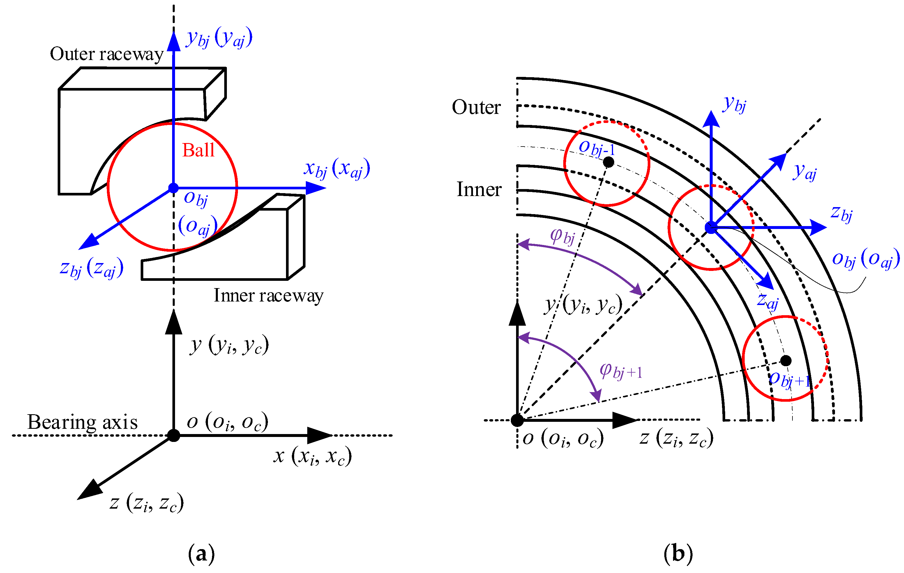
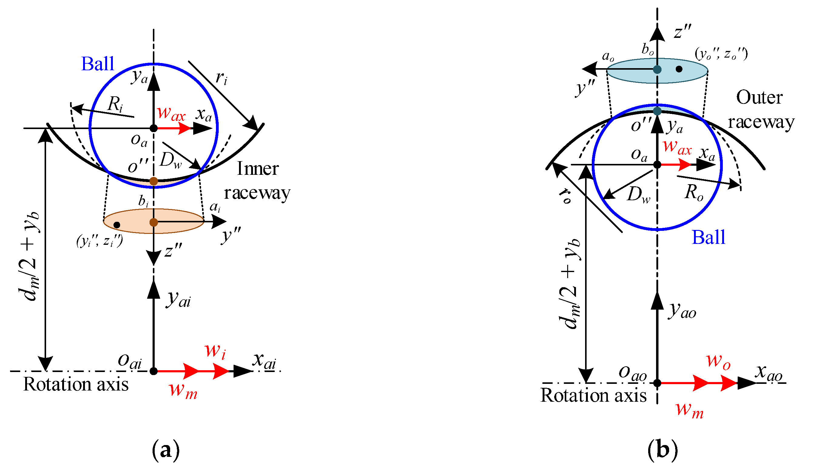
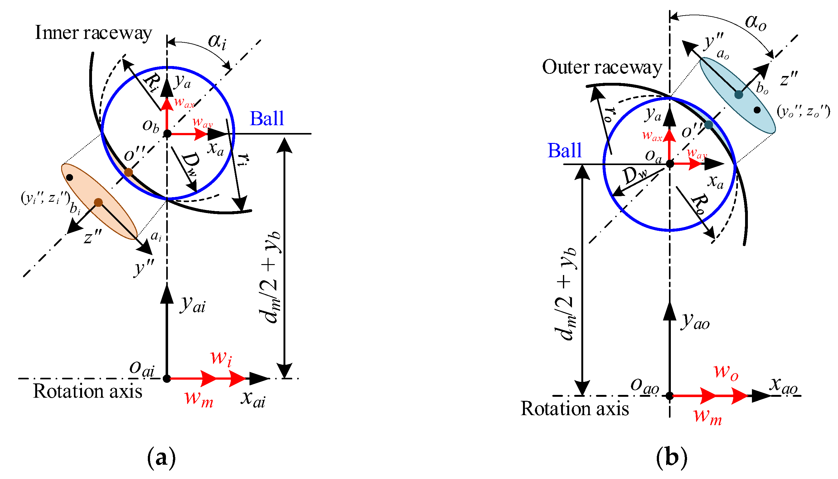
Four coordinate frames must be defined to describe the bearing components’ motion in space, as shown in Figure 1. The first one (o-xyz) is called the inertial coordinate frame; the second one (oi-xiyizi) is the inner-fixed coordinate frame; the third one (oc-xcyczc) donates the cage-fixed coordinate frame; and the fourth one (obj-xbjybjzbj) represents the ball-fixed coordinate frame. To determine the relative motion between the components, the connection between these coordinate frames needs to be created. Furthermore, the azimuthal coordinate frame (oaj-xajyajzaj) is defined to simplify the geometric relationships based on the characteristics of the ball motion.

Figure 1.
Bearing coordinate frames: (a) axial section; (b) radial section.
2.1. Pure Radial Force
- (1)
- Normal load
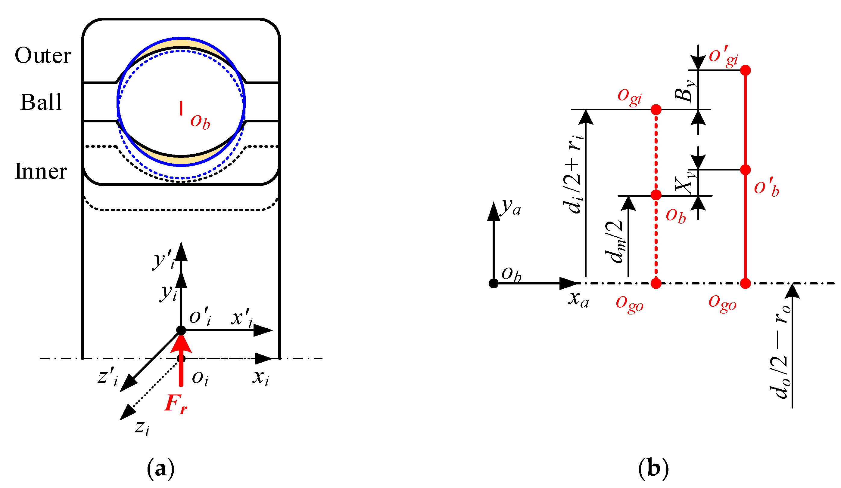
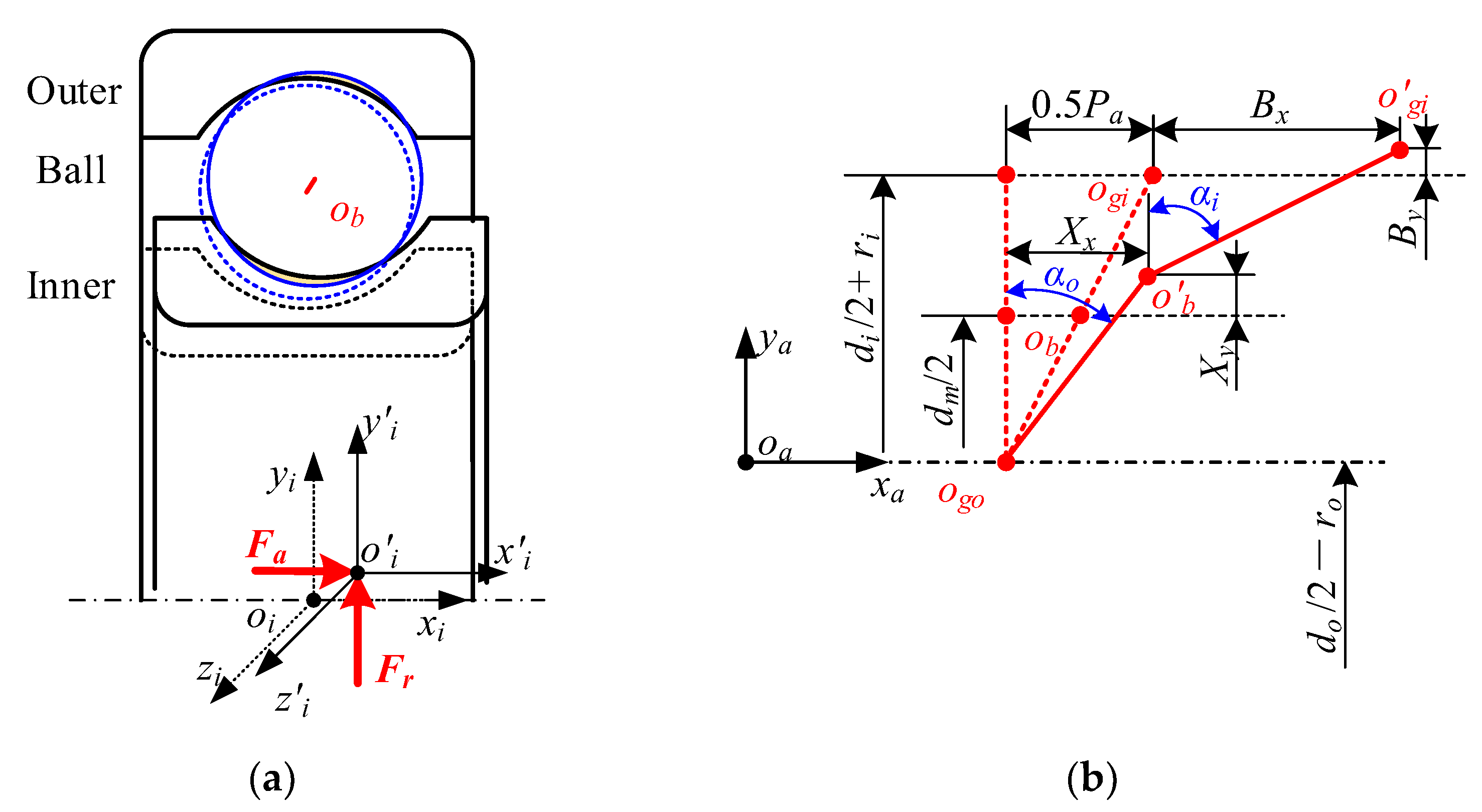
The relative position between the ball and the raceway under pure radial force is presented in Figure 2. The outer ring is assumed to be fixed to the ground, while the inner ring moves in the radial plane under radial load and gradually contacts the ball. The inner ring does move axially because it is not subjected to axial force. The contact deformation between the j-th ball and raceways can be expressed as:
where di/o represents the groove bottom circle diameter of the inner/outer ring. ri/o is the groove curvature radius of the inner/outer ring. Dw means the ball’s diameter. dm indicates the pitch diameter of the bearing, dm = (di + do)/2. By is the displacement of the inner groove curvature center in the azimuthal plane along the yaj-axis, defined by:
where φbj denotes the ball azimuth, φbj = arctan (zbj/ybj).
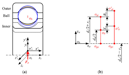
Figure 2.
Relative position relationship between the ball and raceway under pure radial force: (a) schematic diagram of bearings assemblies; (b) positions of the ball’s center and groove curvature centers.
Xy indicates the displacement of the ball’s center in the azimuthal plane, determined by:
The normal load between the ball and the raceway can be calculated by using the Hertzian point contact theory, formulated as [21,32]:
where Ki/o denotes the contact deflection coefficient.
Furthermore, since the ball motion is confined in the radial plane, the working contact angle is always 0°.
- (2)
- Traction force
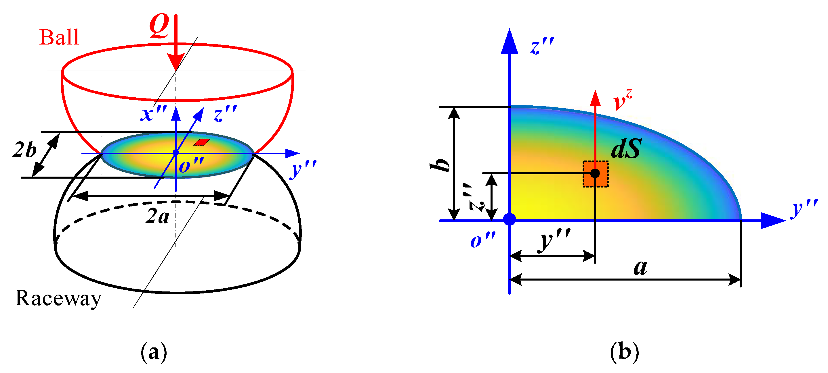
The traction force inside the ball/raceway interface is critical to the bearing’s dynamic performance. Unfortunately, the shear stress distribution in the contact zone is highly dispersed, making it difficult to calculate this force. The micro-element approach is generally used to first discretize the contact area, then solve for the shear stress at each point, and finally integrate to obtain the traction of the entire interface. Because of the presence of lubricant, the shear stress is a function of velocity and pressure. Therefore, the velocity and pressure distributions inside the contact zone must be specified before solving for the traction force. The distribution of these performance parameters in the contact zone under pure radial force is presented in Figure 3.
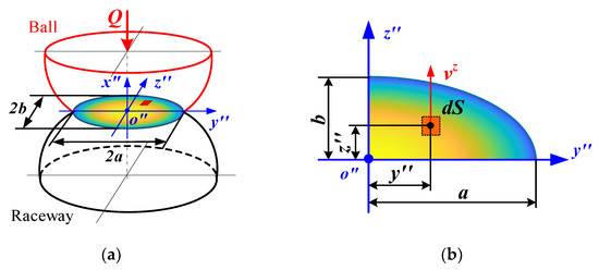
Figure 3.
Distribution of stresses and velocities at ball/raceway interface under pure radial force: (a) schematic diagram of ball/raceway interface; (b) interface discretization.
The velocity distribution inside the contact interface is first investigated, presented in Figure 4. By observing Figure 4a, the velocity vector at any point (yi″, zi″) in the inner raceway can be obtained by the following formula:
where wi denotes the angular velocity of the inner ring. Ri indicates the curvature radius of the contact surface, Ri = (2Dw·ri)/(Dw + 2ri). wm represents the ball orbital angular velocity, wm = (−vby·cos(φbj) + vbz·sin(φbj))/(ybj2 + zbj2)0.5. wax is the ball’s angular velocity about the x-axis in the azimuthal coordinate frame, wax = wbx.
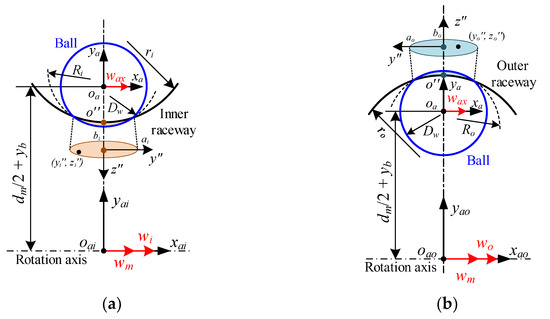
Figure 4.
Velocities distribution at ball/raceway interface under pure radial force: (a) inner raceway; (b) outer raceway.
Similarly, the velocity vector at any point (yo″, zo″) in the outer raceway can be determined by:
In addition, the stress at any point (y″, z″) inside the contact zone can be predicted using the Hertzian contact theory [23]:
where pmax is the maximum contact stress. a and b represent the length of the semi-major axis and the length of the semi-minor axis of the contact ellipse, respectively.
As shown in Figure 3, the shear stress at this point can be further derived as follows [27]:
where S denotes the area of the micrometeoroid. μ represent the traction coefficient, which can be approximated by a five-parameter rheological model [26]:
where A, B, C, and D are functions of lubricant physical parameters and dynamic performance parameters, etc. s indicates the ratio of the relative velocity to the rolling velocity, s = v/u.
The traction force between the ball and raceway can be estimated by integrating the shear stress, denoted as:
- (3)
- Differential equations
Since the bearing assemblies are assumed to be purely rigid bodies in this paper, the relationship between their motion and forces can be modeled by Newton’s law and Euler’s kinematical equations. When the bearing is subjected to radial force only, the inner ring has one degree of freedom (DOF) of translation, and the ball has two DOFs of translation and one DOF of rotation.
For the balls, the differential equations can be defined as follows:
where mb denotes the ball mass. Ib is the rotational inertia. Fcj indicates the ball centrifugal force, Fcj = 0.5·mb·dm·wm2. Fdj means the oil and gas mixture mixing resistance. Qcj represents the interaction between the ball and the cage pocket [33].
For the inner ring, the differential equations can be determined as follows:
where mi indicates the inner mass. Z is the number of the ball.
2.2. Pure Axial Force
- (1)
- Normal load
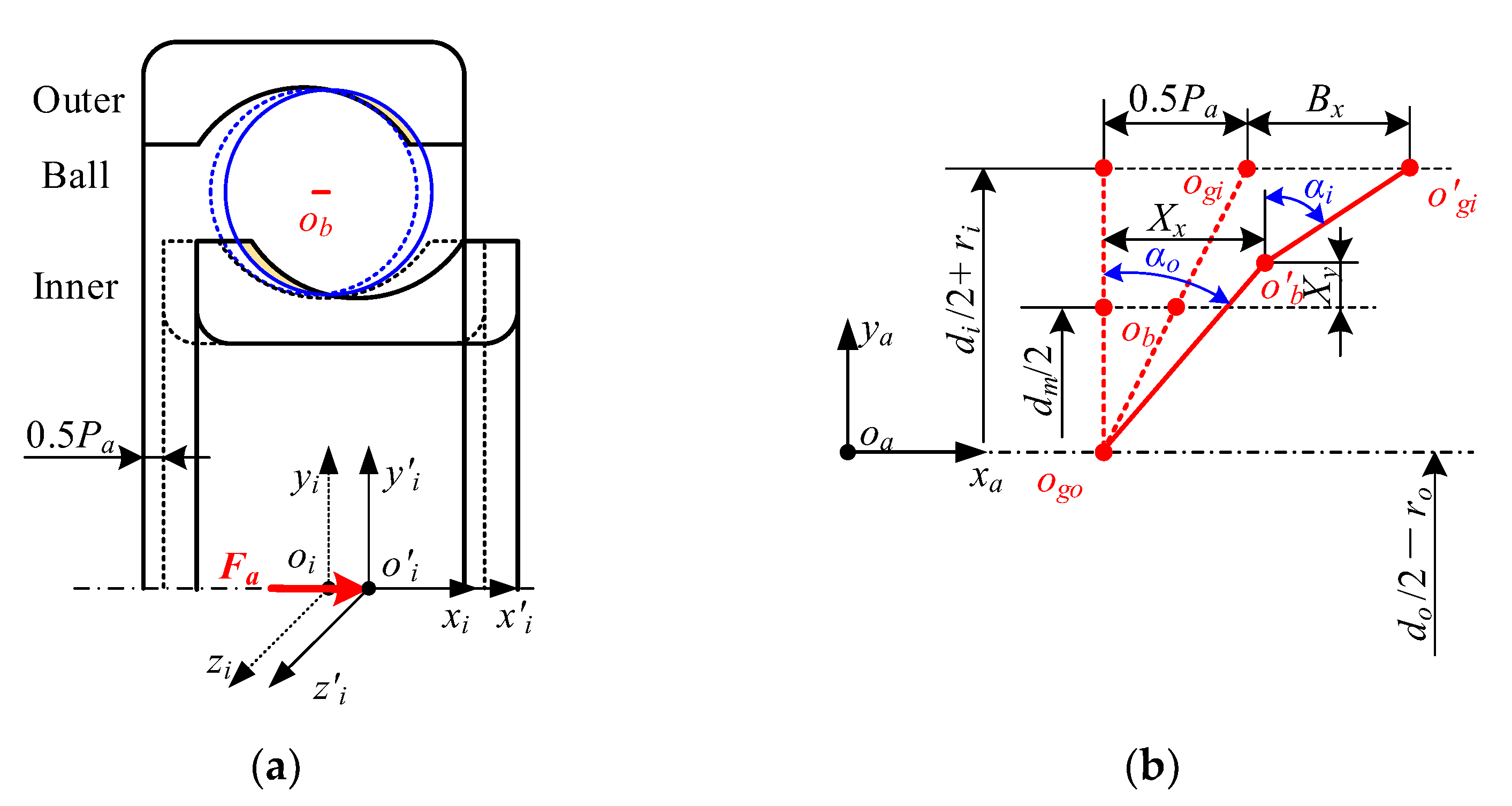
Figure 5 presents the relative position between the ball and the raceway under pure axial force. The axial force moves the inner ring axially, first closing the radial clearance and forming the initial contact angle before entering the preload phase. The ball’s motion changes from one-dimensional to two-dimensional due to the action of centrifugal load and axial force. Similar to pure radial force, the contact deformation between the j-th ball and raceway under pure axial force can be represented as:
where Pa denotes the axial clearance. Bx is the axial displacement of the inner ring and Bx = xi. Xx and Xy are the displacements of the ball in the radial direction and axial direction, respectively, determined by:
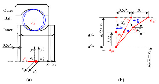
Figure 5.
Relative position relationship between the ball and raceway under pure axial force: (a) schematic diagram of bearing assemblies; (b) positions of the ball’s center and groove curvature centers.
Similarly, the Hertzian contact theory can be employed to establish the connection between the contact deflection and normal load.
The working contact angle under pure axial force can be further developed as:
- (2)
- Traction force
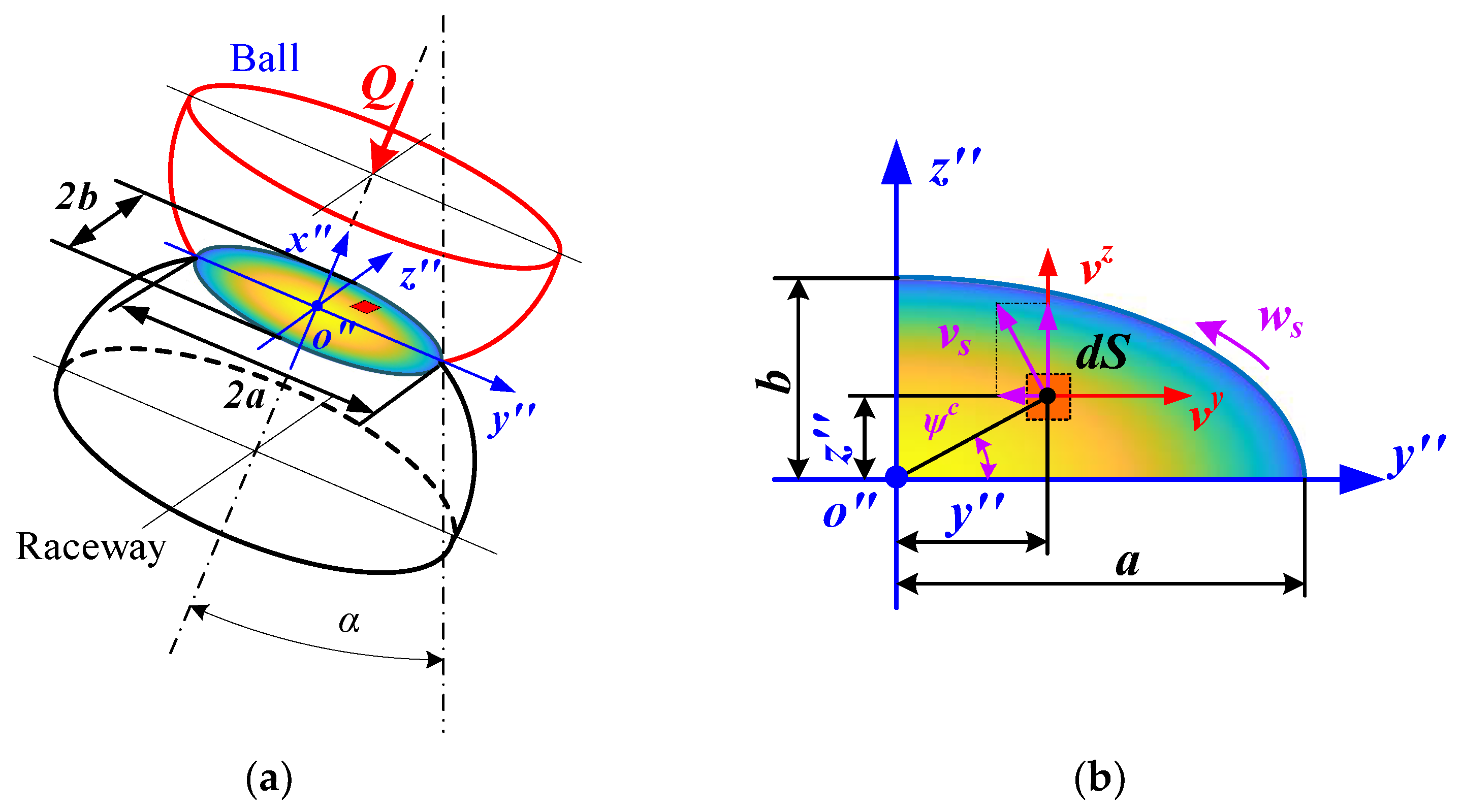
Under pure axial force, a working contact angle is formed between the ball and the inner/outer raceway. Considering the ball’s centrifugal force at high speed, the inner contact angle is larger than the outer contact angle, which can be seen in Figure 5. Figure 6 presents the velocity and stress distribution at the ball/raceway contact interface in the presence of the contact angle. As shown in Figure 6, the velocity distribution under pure axial force is significantly different from that under pure radial force, while the stress distribution is approximately the same for both. This means that the stresses at any point can continue to be predicted using Hertzian contact theory, while a new model needs to be proposed to elucidate the velocity distribution.
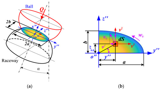
Figure 6.
Distribution of stresses and velocities at ball/raceway interface under pure radial force: (a) schematic diagram of ball/raceway interface; (b) interface discretization.
The presence of the contact angle leads to a linear relative velocity component between the ball and raceway along the major axis of the contact ellipse. The velocity vector inside the contact interface also changes from one-dimensional to two-dimensional. Furthermore, the difference in the two contact angles on the ball generates a rotational velocity at this interface. Therefore, before integrating the traction force, both the linear velocity in each direction and the spin angular velocity inside the contact area must be clarified.
Similar to pure radial force, the velocity distribution inside the contact interface is displayed in Figure 7. As shown in Figure 7a, for any point (xi″, yi″) in the interface of the inner raceway, the translational velocity vector is given by:
where way and waz are the angular velocities of the ball rotating about the y-axis and about the z-axis in the azimuthal coordinate frame, respectively, defined by:
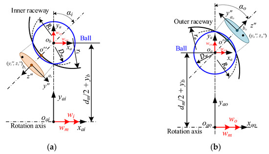
Figure 7.
Velocities distribution at ball/raceway interface under pure radial force: (a) inner raceway; (b) outer raceway.
In addition, the spin angular velocity inside the interface between the ball and the inner raceway can be deduced as follows:
Similarly, the translational velocity vector and the spin angular velocity at any point (xo″, yo″) of the outer raceway can be obtained by:
As shown in Figure 6b, the relative sliding velocity vector is synthesized from the velocity vector and the spin velocity, given by [27]:
Since the ball velocity at the contact interface with respect to the raceway is a two-dimensional vector under pure axial force, its traction force needs to be obtained by integrating the shear stress in both directions [27,34].
Furthermore, in addition to the sliding velocity inside the contact interface, there is a spin velocity around the contact normal, which produces the spin moment.
- (3)
- Differential equations
Once the bearing is subjected to axial force only, the inner ring has one degree of freedom (DOF) of translation, and the ball has three DOFs of translation and three DOFs of rotation.
For the balls, the differential equations can be defined as follows:
For the inner ring, the differential equations can be determined as follows:
where mi indicates the inner mass.
2.3. Combined Axial and Radial Load
- (1)
- Normal load
The position relationship of the bearing’s assemblies with and without the combined axial and radial load is displayed in Figure 8. By observing Figure 8, it can be seen that when the bearing is in this operating condition, the inner displacement changes from the original one-dimensional vector to a two-dimensional vector, greatly increasing the complexity of the spatial position relationship.

Figure 8.
Relative position relationship between the ball and raceway under pure axial force: (a) schematic diagram of bearings assemblies; (b) positions of the ball’s center and groove curvature centers.
Fortunately, the presence of radial force has no effect on the relative position between the ball and the outer raceway compared to the pure axial force condition, which means that the contact force and the contact angle between them can be obtained in this condition using the previous models. Therefore, the contact deformation and contact angle between the ball and inner raceway can be indicated as follows, respectively:
As for traction force, it is perfectly possible to use the previous model of pure axial force to obtain the force under combined axial and radial load. The reason is that in both conditions, the contact interface between the ball and the raceway is a two-dimensional plane.
- (2)
- Differential equations
When the bearing is subjected to combined axial and radial force, the inner ring has two degrees of freedom (DOFs) of translation, and the ball has three DOFs of translation and three DOFs of rotation. Furthermore, the differential equations of the ball are the same as those under pure axial force.
For the inner ring, the differential equations can be expressed as follows:
3. Theoretical Model Solving and Validation
In this section, the solution procedure of the previous numerical model is presented in detail. The validation of this model is further proven by comparing it with the experimental data of Han [35] and Pasdari [36]. Furthermore, the superiority of this model is highlighted by comparing it with the simulation results of Han [35] and Liu [26].
3.1. Model Solving
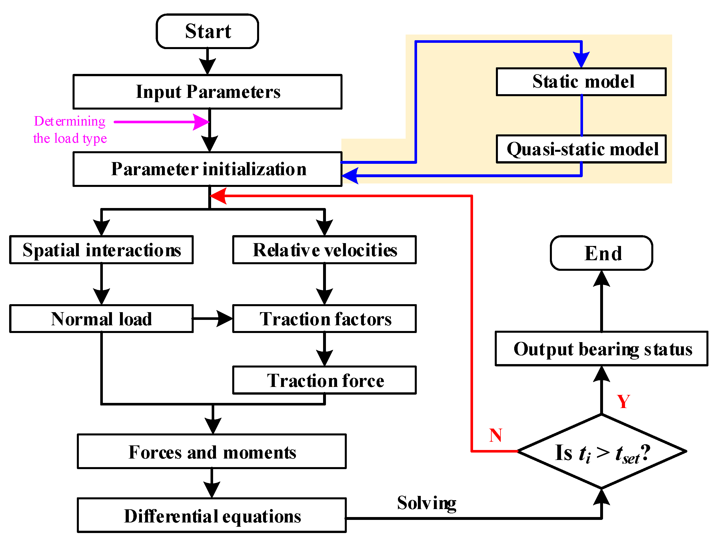
The flowchart for solving the general dynamic model of ball bearings is presented in Figure 9. This process can be divided into three steps, covering: parameters input and initialization, main calculations, and post-processing. Compared to the common ball bearing dynamics model, the improvement of this model is primarily reflected in the first two steps. After entering the parameters, the program quickly selects a model with a specific number of equations based on the load type entered. The issue of increasing the computational cost due to many unnecessary variables taking up memory is avoided, as is the problem of model divergence. Furthermore, because of the complex motion of the bearing components, it is necessary to ensure the accuracy of the initial values when solving the differential equations. This is commonly accomplished through the static model and the quasi-static model. The number of equations to be solved for the present model is listed in Table 1. The current model is capable of reducing iterative variables by reducing the dimensionality of the equation set, thus saving computational cost.
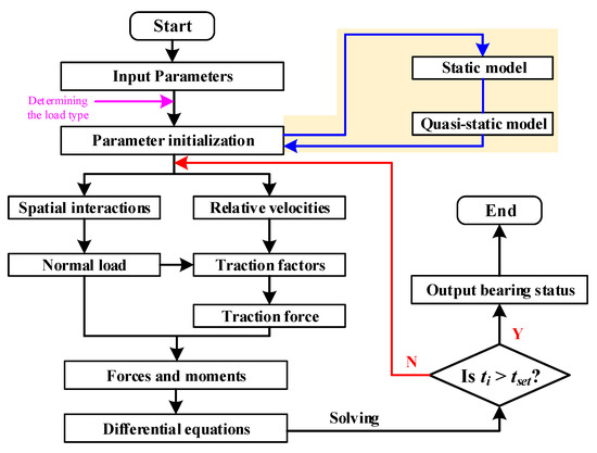
Figure 9.
Flowchart for solving the general dynamic model of ball bearings.

Table 1.
The number of equations to be solved for each operating condition.
3.2. Model Validation
To validate the reliability of the model proposed in this paper, its prediction results under two different operating conditions are compared with the experimental results [35,36], respectively. Since the bearing model for the pure axial force condition is approximately the same as the model for the combined axial and radial load, only the simulation results for the pure axial force are verified.
To verify the accuracy of the present model under pure radial force conditions, the driving speed of the bearing is kept at 1800 r/min and the radial force is incremented from 50 N to 300 N, and the model prediction results are compared with the experimental results in Ref. [35]. As for the pure axial force conditions, the radial force is increased from 10 N to 400 N at a driving speed of 4000 r/min, and the prediction is compared with the experimental results in Ref. [36]. The variations of cage speed with different loads for two operating conditions are described in Figure 10, respectively. The cage speed gradually increases and stabilizes with the growing load, indicating that the bearing sliding is suppressed. Furthermore, the good agreement between the model’s predicted results and the experimental test results suggests its accuracy under three different operating conditions.
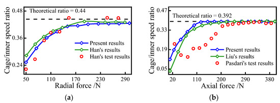
Figure 10.
Comparison of simulation results with experimental data; (a) radial force; (b) axial force.
Moreover, the simulation results of Han’s model [35] and Liu’s model [26] are shown in Figure 10, and the number of equations to be solved for these models is listed in Table 1 as a general model. The results of the model in this paper do not differ much from those of other models, which proves that it reduces the number of variables and equations and improves efficiency without losing computational accuracy. Therefore, the superiority of the model in this paper over the general models is emphasized.
4. Results and Discussion
In this section, angular contact ball bearing 7008 is chosen to investigate the bearing skidding behavior under 3 operating conditions. Its structural parameters and material properties are listed in Table 2. The bearing speed is always kept at 5000 r/min.
Table 2.
Structural parameters and material properties of 7008.
4.1. Case 1: Pure Radial Force
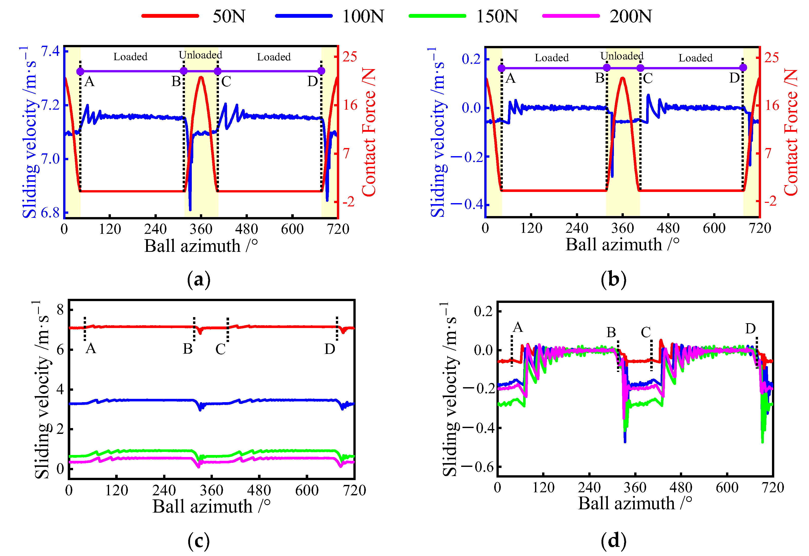
Applying radial forces of 50, 100, 150, and 200 to the bearing, the sliding behavior of ball bearings under pure radial force is first discussed. The variation of the sliding velocity at the ball/raceway under different loads is presented in Figure 11. Figure 11a,b displays the relationship between the sliding velocity and the normal load for a radial force of 50 N. As shown in Figure 11a, the ball’s sliding velocity is strongly influenced by the load exerted on the ball. To further clearly illustrate the relationship between them, the two running cycles of the ball can be divided into four phases: AB, BC, CD, and DA stages. AB region and CD region denote the loaded zone, while the other two regions represent the unloaded zones. Interestingly, at the intersection of the two phases, the sliding velocity fluctuates considerably, indicating that the abrupt changes in the sliding velocity tend to occur near the boundary of the loaded zone. In addition, for the inner raceway, the steady value of the sliding velocity in the non-loaded zone is greater than in the loaded zone. The opposite phenomenon is observed in the outer raceway, as shown in Figure 11b. This is because the driving force provided by the inner raceway in the loaded zone is heavier than the resistance of the outer ring, whereas, in the unload zone, only the outer resistance exists. Furthermore, the sliding velocity between the inner raceway and the ball is up to 7 m/s or more in the loaded zones, indicating severe sliding inside the bearing under a radial force of 50 N.
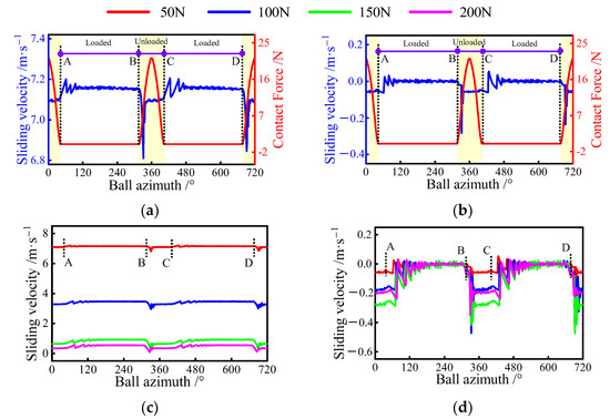
Figure 11.
Sliding velocity variation at ball/raceway interface under pure radial force condition, A denotes the exit of the previous loaded area, B is the entrance of the current loaded area, C represents the exit of the current loaded area, D is the entrance of the next loaded area: (a) sliding velocity of the inner raceway for different azimuths; (b) sliding velocity of the outer raceway for different azimuths; (c) sliding velocity of inner raceway; (d) sliding velocity of the outer raceway.
To further discuss the effect of radial force on the bearing sliding, the trend of sliding velocity between the raceways and the ball under different radial loads is provided in Figure 11c,d. It can be seen that as the radial force increases, the sliding velocity between the inner raceway and the ball decreases significantly, while the amount of the change in sliding velocity at the loaded zone boundary increases. Interestingly, the radial load has little effect on the sliding velocity in the unloading zone of the outer raceway as compared to the inner raceway. However, in the load zone, the velocity increases with the gradual increase of the radial load and then decreases.
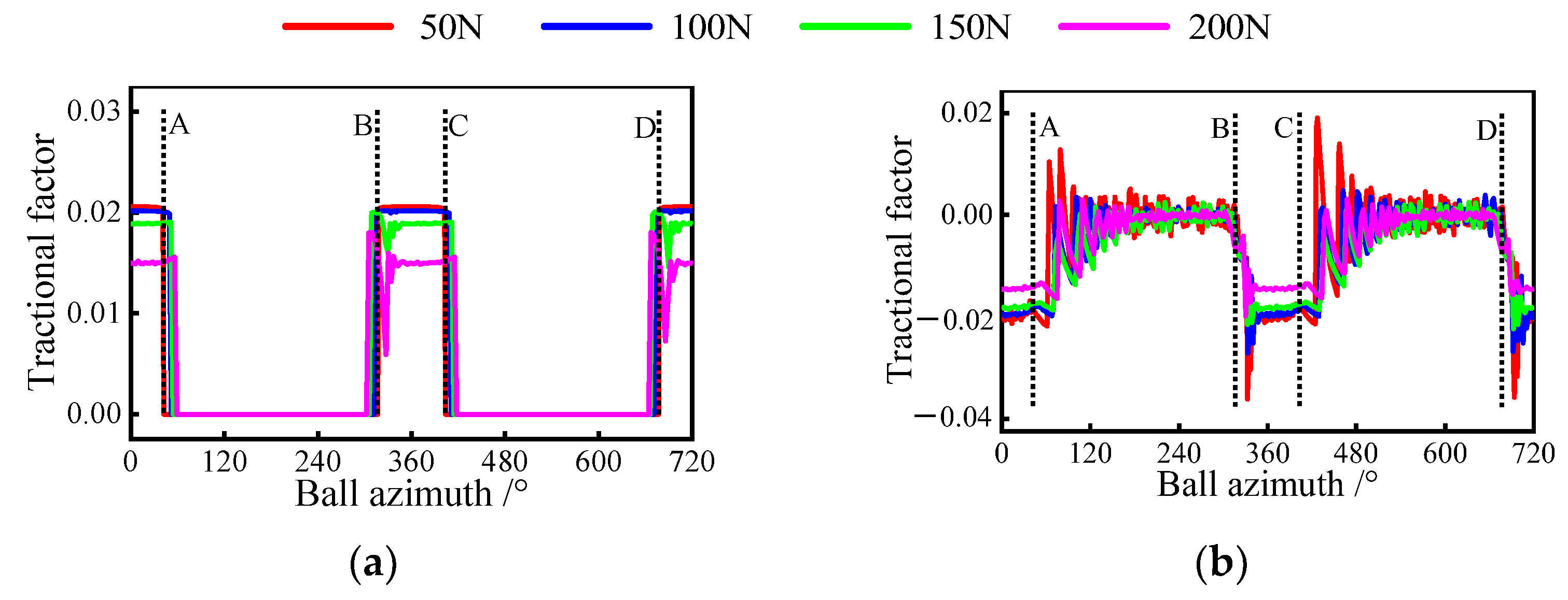
Furthermore, as an essential dynamic indicator, the traction factor has been also investigated. Figure 12 presents the variation of this factor with different loads under pure radial force conditions. By observing Figure 12a, it can be seen that the traction factor between the inner ring and the ball exists only in the load zone. This is because there is no contact load to form a lubricant film in the unloading zone. In addition, the factor first remains constant and then decreases with the gradual growth of the radial force in the loaded zone. A similar phenomenon can be observed in the outer raceway, as shown in Figure 12b. The reason for this is that when the radial load is too tiny to inhibit severe sliding inside the bearing, the traction factor is mainly determined by the sliding velocity. Once the bearing skidding is suppressed, the traction factor is a function of normal load and sliding velocity. Furthermore, the inhibition of sliding leads to an increase in the ball’s centrifugal force, which helps to reduce the flotation of the traction factor between the ball and the outer raceway in the unloading zone.
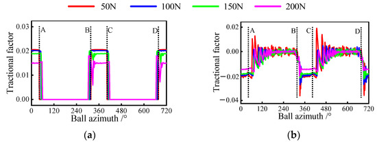
Figure 12.
Tractional factor variation at ball/raceway interfaces under pure radial force condition, A denotes the exit of the previous loaded area, B is the entrance of the current loaded area, C represents the exit of the current loaded area, D is the entrance of the next loaded area: (a) tractional factor of inner raceway; (b) tractional factor of the outer raceway.
4.2. Case 2: Pure Axial Force
The sliding behavior at the ball/raceway interface under pure axial force is then considered. Figure 13a,b shows the sliding velocity on the ball at different azimuths when an axial force of 50 N is applied to the bearing. It can be seen that the velocity between the ball and the raceway remains constant at each revolution. In addition, the sliding velocity on the inner raceway is always greater than that of the outer raceway. This is due to the fact that the contact features of the ball at different azimuths are equal when the bearing is operating in pure axial condition. Therefore, the effect of axial force on the sliding behavior is further investigated with a certain ball.
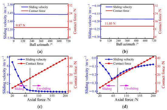
Figure 13.
Sliding velocity variation at ball/raceway interface under pure axial force condition: (a) sliding velocity of the inner raceway for different azimuths; (b) sliding velocity of the outer raceway for different azimuths; (c) sliding velocity of inner raceway; (d) sliding velocity of the outer raceway.
Increasing the axial force from 20 N to 200 N, the change in sliding velocity on the ball is presented in Figure 13c,d. Similar to the pure radial force condition, the sliding inside the bearing is inhibited as the load is gradually increased. Once the axial force exceeds 80 N, the sliding velocity on the inner raceway stays in a small variation, while the outer velocity tends to become smaller. In addition, the sliding velocity on the inner raceway is gradually equal to the velocity of the outer, indicating that the skidding inside the bearing is completely suppressed. Interestingly, the inflection point of the sliding velocity on the outer occurs before the axial force reaches 80 N. This means that the normal load on the ball does not completely determine the degree of sliding at the ball/outer raceway interface.
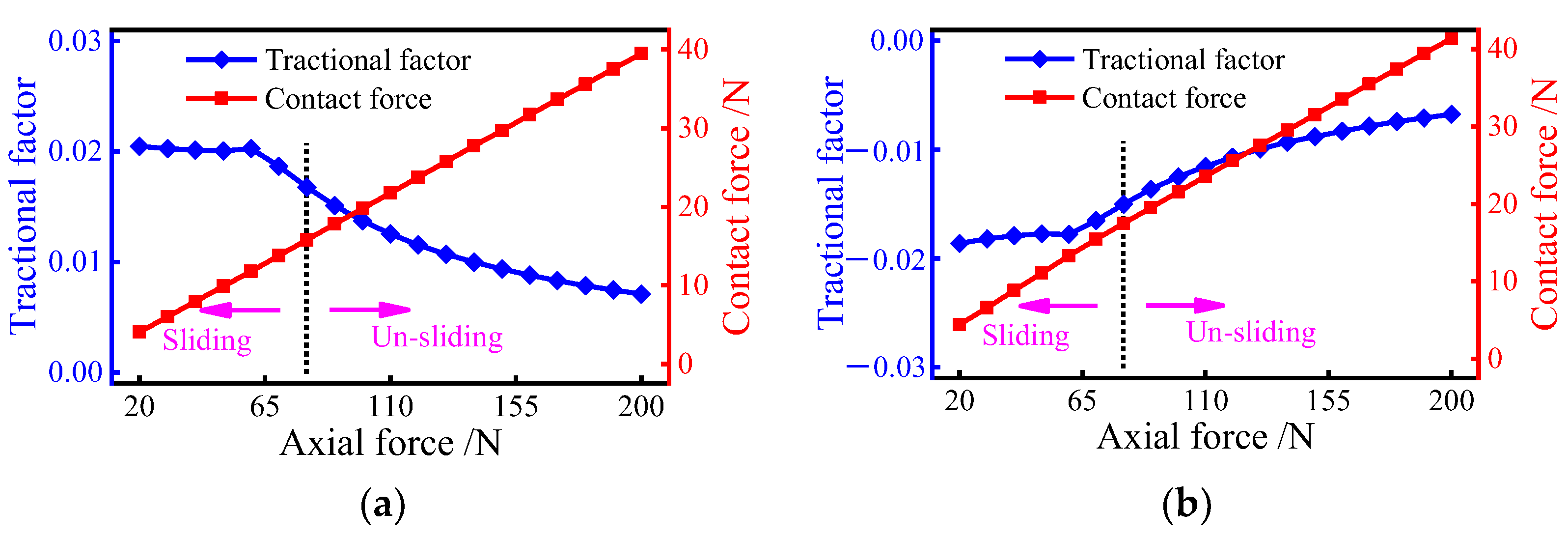
The effect of the axial force on the traction factor is further discussed. As shown in Figure 14, when the axial load is less than 60 N, the traction factor of the inner and outer raceways keeps fluctuating around a large value. Meanwhile, the factor of the inner raceway is bigger than that of the outer raceway. This is because, for ball bearings subjected to axial loads only, the traction coefficient at the ball/raceway interface is greatly influenced by the slip-roll ratio. When the load is too tiny to suppress severe sliding inside the bearing, the slip-roll ratio at the interface will be larger, resulting in a larger value of the traction coefficient. Once the axial force exerted on the bearing is greater than 60 N, the traction factor of the inner and outer raceways tends to decrease. Although the traction factor tends to decrease when the axial force is between 60 N and 80 N, the sliding velocity is still high, which significantly reduces the bearing performance. This indicates that the load causing the shift in the traction factor is less than the critical load to prevent bearing sliding. As a result, it is better to choose an axial force of 80 N or greater as the bearing’s normal working load to avoid serious sliding.
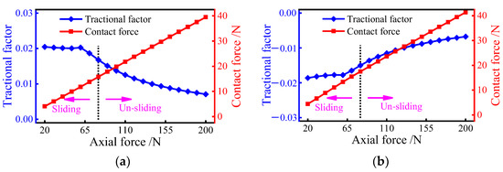
Figure 14.
Tractional factor variation at ball/raceway interfaces under pure axial force condition: (a) tractional factor of inner raceway; (b) tractional factor of the outer raceway.
4.3. Case 3: Combined Axial and Radial Force
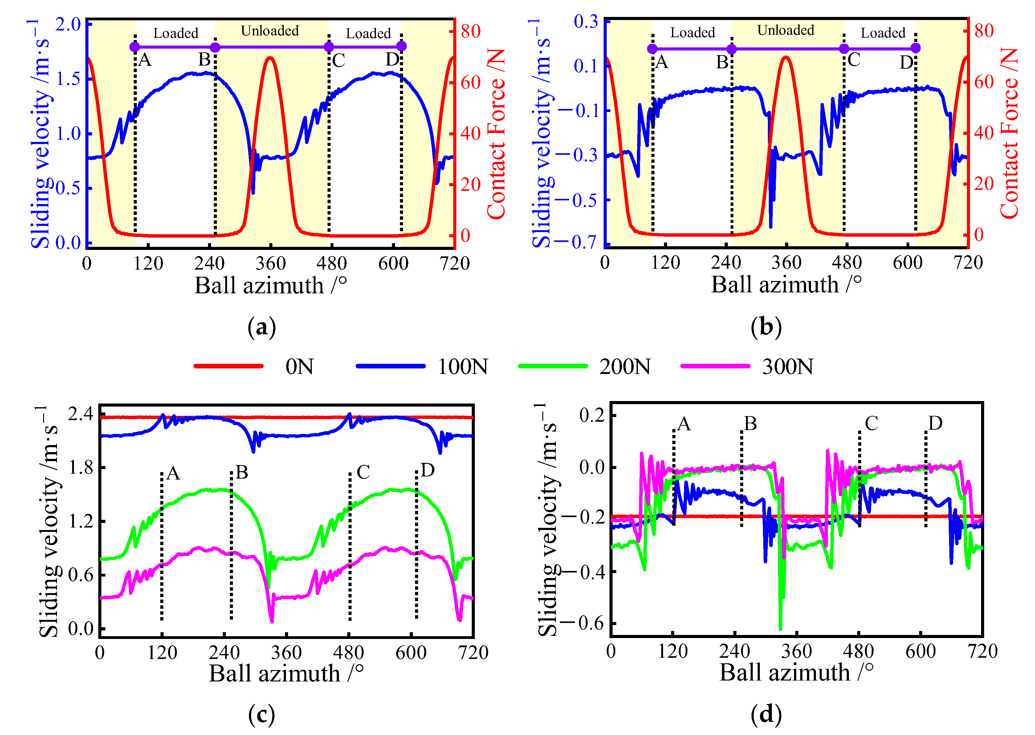
Under combined axial and radial force conditions, the load distribution on the ball is non-uniform due to the presence of radial load. Once the radial load is too larger, the ball experiences the loaded and unloaded zones in turn for each revolution. Therefore, the sliding behavior of the ball at different azimuths is significantly different. Figure 15a,b display the variation of the ball’s sliding velocity for an axial force of 100 N and a radial force of 200 N. Similar to pure radial force condition, the ball goes through four stages in sequence for every two revolutions, covering: the AB phase, BC phase, CD phase, and DA phase. In the AB phase, the sliding velocity on the inner raceway tends to increase and the velocity of the outer remains constant; in the BC phase, the inner raceway’s sliding velocity is smaller and stabilizes as the normal load increases, while the sliding velocity of the outer changes in the opposite trend. The sliding behavior of the ball changes in the other two phases in the same way as in the first two phases. In fact, the sliding variation at the ball/raceway interface is mainly influenced by its contact features.
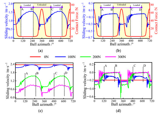
Figure 15.
Sliding velocity variation at ball/raceway interface under combined axial and radial load conditions, A denotes the exit of the previous loaded area, B is the entrance of the current loaded area, C represents the exit of the current loaded area, D is the entrance of the next loaded area: (a) sliding velocity of the inner raceway for different azimuths; (b) sliding velocity of the outer raceway for different azimuths; (c) sliding velocity of inner raceway; (d) sliding velocity of the outer raceway.
The radial force is gradually increased from 0 N to 300 N to further investigate the sliding behavior under this condition. Figure 15c,d presents the changes in the sliding velocity under different radial forces. Although the floating range of the speed is small when the radial force is small, the overall sliding velocity inside the bearing is severe. With the gradual increase of the radial force, the variation of sliding velocity on the ball increases, but its maximum value decreases. In addition, a similar phenomenon can be observed at the ball/outer raceway interface.
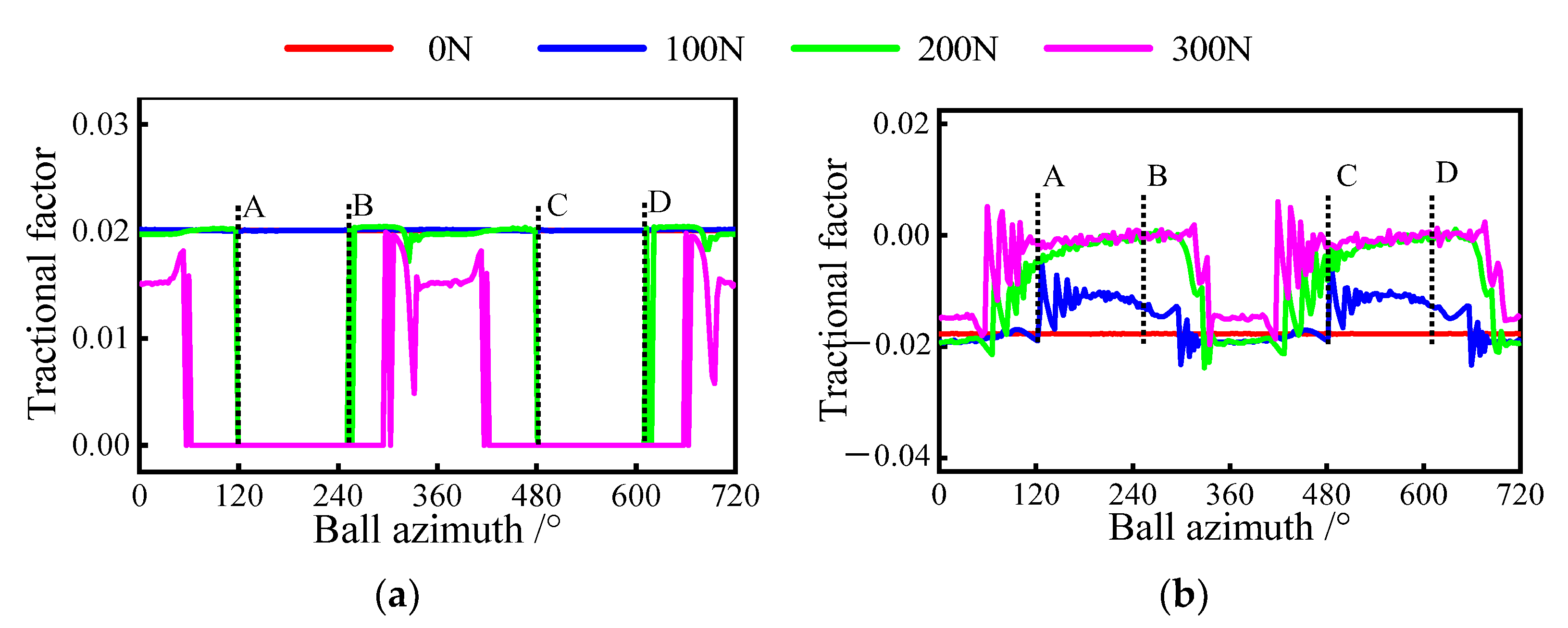
As shown in Figure 16a,b, the traction factors of the outer and inner raceway are strongly influenced by the radial load in this case. Once the load exceeds 200 N, the traction factor in the inner raceway starts to appear as 0. This is due to excessive radial forces, which cause a portion of the loaded zone to become an unloaded zone. By observing Figure 16a, the unloaded zone gradually expands with the increase of radial force. It is noteworthy that the traction factor on the outer raceway is never zero regardless of the radial force, which is due to the non-zero contact force at the ball/outer raceway interface. Furthermore, when the bearing’s sliding is inhibited, the traction factor gradually decreases as the load decreases, similar to the first two operating conditions.
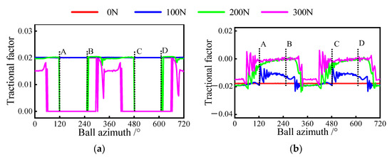
Figure 16.
Tractional factor variation at ball/raceway interface under combined axial and radial load condition, A denotes the exit of the previous loaded area, B is the entrance of the current loaded area, C represents the exit of the current loaded area, D is the entrance of the next loaded area: (a) tractional factor of inner raceway; (b) tractional factor of the outer raceway.
5. Conclusions
In this paper, a generic ball-bearing dynamic model for predicting sliding behavior is presented. Specific geometric interactions between the ball and raceway are constructed based on the motion features between the components under different operating conditions. The number of iteration variables and equations are determined by the load vector exerted on the bearing to improve the convergence and efficiency of the model. The sliding behavior under three typical operating conditions is further discussed. The conclusions are as follows:
- (1)
- When the bearing is subjected to pure axial force, the sliding velocity in the outer raceway first increases and then decreases as the load increases;
- (2)
- Under combined load conditions, the heavy radial forces inhibit the bearing sliding while exacerbating the non-uniformity of the sliding distribution;
- (3)
- Once the unloaded zone occurs, the sliding velocity between the ball and the inner raceway is less in the loaded zone than in the unloaded zone. While the velocity on the outer raceway has the opposite trend;
- (4)
- The increased load helps to suppress severe sliding behavior inside the bearing but shortens the bearing fatigue life.
The presented investigations show that the increase in load helps to inhibit sliding inside the bearing, thus extending the bearing’s fatigue life. However, excessive loads can lead to premature fatigue damage of the bearing and shorten its fatigue life. Therefore, during the bearing design process, dynamic models can be used to investigate bearing sliding to guide the optimization of its performance. In addition, the traction model for the ball/raceway interface in the proposed model is too simplified to ignore the viscous temperature and pressure effects within the interface. Hopefully, future research will remedy this deficiency.
Author Contributions
Conceptualization, S.M., F.C., B.F., K.Y. and J.H.; Data curation, S.M.; Formal analysis, S.M. and Y.Y.; Funding acquisition, J.H.; Investigation, S.M. and K.Y.; Methodology, S.M., and Y.Y.; Project administration, K.Y. and J.H.; Resources, J.H.; Software, S.M.; Supervision, K.Y.; Validation, Y.Y.; Visualization, Y.Y. and J.H.; Writing—original draft, S.M. and K.Y.; Writing—review & editing, K.Y., Y.Y. and J.H. All authors have read and agreed to the published version of the manuscript.
Funding
This research was founded by the National Key R&D Program of China (2020YFB2007901).
Data Availability Statement
Not applicable.
Conflicts of Interest
The authors declare no conflict of interest.
Abbreviations
| Symbols | Meaning |
| δ | Contact deformation |
| Bx/y | Inner groove curvature center’s displacement |
| Xx/y | Ball center’s displacement |
| Qi/o | Inner/outer normal load |
| Qc | Ball/pocket interaction force |
| Mx | Spin moment |
| p | Contact stress |
| τ | Shear stress |
| μ | Traction coefficient |
| Ti/o | Inner/outer traction load |
| αi/o | Working contact angle |
| m | Mass |
| I | Rotational inertia |
| Fc | Ball centrifugal force |
| Fdj | Oil and gas mixture mixing resistance |
| di/o | Groove bottom circle diameter of inner/outer ring |
| ri/o | Groove curvature radius of inner/outer ring |
| Dw | Ball diameter |
| dm | Bearing pitch diameter |
| Ri | Curvature radius of the contact surface |
| Z | Ball number |
| Pa | Axial clearance |
| φbj | Ball azimuth |
| Ki/o | Contact deflection coefficient |
| v | Sliding velocity |
| u | Rolling velocity |
| wm | Ball orbital angular velocity |
| wbx | Ball rotation angular velocity |
| ws | Spin velocity |
| pmax | Maximum contact stress |
| S | Micrometeoroid’s area |
| A, B, C, D | Lubricant parameters |
| s | Slide-roll ratio |
| Fa | Axial load |
| Fr | Radial load |
| o-xyz | Inertial coordinate frame |
| oi-xiyizi | Inner-fixed coordinate frame |
| oc-xcyczc | Cage-fixed coordinate frame |
| ob-xbybzb | Ball-fixed coordinate frame |
| oa-xayaza | Azimuthal coordinate frame |
References
- Cocks, M.; Tallian, T.E. Sliding Contacts in Rolling Bearings. ASLE Trans. 1971, 14, 32–40. [Google Scholar] [CrossRef]
- Qian, D.; Xu, X.; Deng, S.; Jiang, S.; Hua, L. Sliding behavior of high speed ball bearings based on improved nonlinear dynamic model. Proc. Inst. Mech. Eng. Part K J. Multi-Body Dyn. 2021, 235, 627–640. [Google Scholar] [CrossRef]
- Gupta, P.K. Minimum Energy Hypothesis in Quasi-Static Equilibrium Solutions for Angular Contact Ball Bearings. Tribol. Trans. 2020, 63, 1051–1066. [Google Scholar] [CrossRef]
- Zhang, P.; Pan, A.; Yan, K.; Sun, J. High stability temperature sensors by CdTe quantum dots encapsulated in SiO2/PVA hybrids for bearing rotating elements. Mater. Today Commun. 2023, 34, 105456. [Google Scholar] [CrossRef]
- Jorgensen, B.R.; Shin, Y. Dynamics of Machine Tool Spindle/Bearing Systems Under Thermal Growth. J. Tribol. 1997, 119, 875–882. [Google Scholar] [CrossRef]
- Aramaki, H.; Shoda, Y.; Morishita, Y.; Sawamoto, T. The Performance of Ball Bearings With Silicon Nitride Ceramic Balls in High Speed Spindles for Machine Tools. J. Tribol. 1988, 110, 693–698. [Google Scholar] [CrossRef]
- Harris, T. Rolling Bearing Analysis, 2nd ed.; John Wiley & Sons: New York, NY, USA, 1984. [Google Scholar]
- Xu, T.; Xu, G.; Zhang, Q.; Hua, C.; Tan, H.; Zhang, S.; Luo, A. A preload analytical method for ball bearings utilising bearing skidding criterion. Tribol. Int. 2013, 67, 44–50. [Google Scholar] [CrossRef]
- Liao, N.T.; Lin, J.F. Ball bearing skidding under radial and axial loads. Mech. Mach. Theory 2002, 37, 91–113. [Google Scholar] [CrossRef]
- Liao, N.-T.; Lin, J.F. Rolling-Sliding Analysis in Ball Bearing Considering Thermal Effect. Tribol. Trans. 2006, 49, 1–16. [Google Scholar] [CrossRef]
- Hirano, F. Motion of a Ball in Angular-Contact Ball Bearing. ASLE Trans. 1965, 8, 425–434. [Google Scholar] [CrossRef]
- Oktaviana, L.; Tong, V.-C.; Hong, S.-W. Skidding analysis of angular contact ball bearing subjected to radial load and angular misalignment. J. Mech. Sci. Technol. 2019, 33, 837–845. [Google Scholar] [CrossRef]
- Nelias, D.; Bercea, I.; Paleu, V. Prediction of Roller Skewing in Tapered Roller Bearings. Tribol. Trans. 2008, 51, 128–139. [Google Scholar] [CrossRef]
- Cao, H.; Niu, L.; Xi, S.; Chen, X. Mechanical model development of rolling bearing-rotor systems: A review. Mech. Syst. Signal Process. 2018, 102, 37–58. [Google Scholar] [CrossRef]
- Meeks, C.R.; Ng, K.O. The Dynamics of Ball Separators in Ball Bearings—Part I: Analysis. ASLE Trans. 1985, 28, 277–287. [Google Scholar] [CrossRef]
- Meeks, C.R.; Tran, L. Ball Bearing Dynamic Analysis Using Computer Methods—Part I: Analysis. J. Tribol. 1996, 118, 52–58. [Google Scholar] [CrossRef]
- Jones, A.B. Ball Motion and Sliding Friction in Ball Bearings. Trans. ASME J. Basic Eng. 1959, 81, 1–12. [Google Scholar] [CrossRef]
- Jones, A.B. A General Theory for Elastically Constrained Ball and Radial Roller Bearings Under Arbitrary Load and Speed Conditions. J. Basic Eng. 1960, 82, 309–320. [Google Scholar] [CrossRef]
- Jain, S.; Hunt, H. A dynamic model to predict the occurrence of skidding in wind-turbine bearings. J. Phys. Conf. Ser. 2011, 305, 012027. [Google Scholar] [CrossRef]
- Han, Q.; Chu, F. Nonlinear dynamic model for skidding behavior of angular contact ball bearings. J. Sound Vib. 2015, 354, 219–235. [Google Scholar] [CrossRef]
- Gao, S.; Chatterton, S.; Naldi, L.; Pennacchi, P. Ball bearing skidding and over-skidding in large-scale angular contact ball bearings: Nonlinear dynamic model with thermal effects and experimental results. Mech. Syst. Signal Process. 2020, 147, 107120. [Google Scholar] [CrossRef]
- Gupta, P. Advanced Dynamics of Rolling Bearings; Springer: Boston, MA, USA, 2013. [Google Scholar] [CrossRef]
- Wang, Y.; Wang, W.; Zhang, S.; Zhao, Z. Investigation of skidding in angular contact ball bearings under high speed. Tribol. Int. 2015, 92, 404–417. [Google Scholar] [CrossRef]
- Wang, Y.; Wang, W.; Zhao, Z. Effect of race conformities in angular contact ball bearing. Tribol. Int. 2016, 104, 109–120. [Google Scholar] [CrossRef]
- Yunlong, W.; Wenzhong, W.; Shengguang, Z.; Ziqiang, Z. Effects of raceway surface roughness in an angular contact ball bearing. Mech. Mach. Theory 2018, 121, 198–212. [Google Scholar] [CrossRef]
- Liu, Y.; Wang, W.; Qing, T.; Zhang, Y.; Liang, H.; Zhang, S. The effect of lubricant temperature on dynamic behavior in angular contact ball bearings. Mech. Mach. Theory 2020, 149, 103832. [Google Scholar] [CrossRef]
- Ma, S.; Li, W.; Yan, K.; Li, Y.; Zhu, Y.; Hong, J. A study on the dynamic contact feature of four-contact-point ball bearing. Mech. Syst. Signal Process. 2022, 174, 109111. [Google Scholar] [CrossRef]
- Xu, H.; Wang, P.; Ma, H.; He, D.; Zhao, X.; Yang, Y. Analysis of axial and overturning ultimate load-bearing capacities of deep groove ball bearings under combined loads and arbitrary rotation speed. Mech. Mach. Theory 2021, 169, 104665. [Google Scholar] [CrossRef]
- Li, B.L.; Zeng, L. Fractional Calculus Control of Road Vehicle Lateral Stability after a Tire Blowout. Mechanika 2021, 27, 475–482. [Google Scholar] [CrossRef]
- Walczak, M.; Caban, J. Tribological characteristics of polymer materials used for slide bearings. Open Eng. 2021, 11, 624–629. [Google Scholar] [CrossRef]
- Gil, L.; Przystupa, K.; Pieniak, D.; Kozłowski, E.; Antosz, K.; Gauda, K.; Izdebski, P. Influence of Contamination of Gear Oils in Relation to Time of Operation on Their Lubricity. Appl. Sci. 2021, 11, 11835. [Google Scholar] [CrossRef]
- Fang, B.; Zhang, J.; Hong, J.; Yan, K. Research on the Nonlinear Stiffness Characteristics of Double-Row Angular Contact Ball Bearings under Different Working Conditions. Lubricants 2023, 11, 44. [Google Scholar] [CrossRef]
- Wang, M.; Yan, K.; Zhang, X.; Zhu, Y.; Hong, J. A comprehensive study on dynamic performance of ball bearing considering bearing de-formations and ball-inner raceway separation. Mech. Syst. Signal Process. 2023, 185, 109826. [Google Scholar] [CrossRef]
- Ma, S.; Yin, Y.; Chao, B.; Yan, K.; Fang, B.; Hong, J. A real-time coupling model of bearing-rotor system based on semi-flexible body element. Int. J. Mech. Sci. 2023, 245, 108098. [Google Scholar] [CrossRef]
- Han, Q.; Li, X.; Chu, F. Skidding behavior of cylindrical roller bearings under time-variable load conditions. Int. J. Mech. Sci. 2018, 135, 203–214. [Google Scholar] [CrossRef]
- Pasdari, M.; Gentle, C.R. Effect of Lubricant Starvation on the Minimum Load Condition in a Thrust-Loaded Ball Bearing. ASLE Trans. 1987, 30, 355–359. [Google Scholar] [CrossRef]


Disclaimer/Publisher’s Note: The statements, opinions and data contained in all publications are solely those of the individual author(s) and contributor(s) and not of MDPI and/or the editor(s). MDPI and/or the editor(s) disclaim responsibility for any injury to people or property resulting from any ideas, methods, instructions or products referred to in the content. |
© 2023 by the authors. Licensee MDPI, Basel, Switzerland. This article is an open access article distributed under the terms and conditions of the Creative Commons Attribution (CC BY) license (https://creativecommons.org/licenses/by/4.0/).