Article

Coated Piston Ring Pack and Cylinder Liner Elastodynamics in Correlation to Piston Subsystem Elastohydrodynamic: Through FEA Modelling

1
Department of Mechanical Engineering, Veer Surendra Sai University of Technology, Burla 768018, India
2
School of Mechanical Engineering, KIIT University, Bhubaneswar 751024, India
3
School of Electrical Engineering, Veer Surendra Sai University of Technology, Burla 768018, India
4
Department of Production Engineering, Veer Surendra Sai University of Technology, Burla 768018, India
5
Department of Mechanical Engineering, DIT University, Dehradun 248001, India
*
Authors to whom correspondence should be addressed.
Lubricants 2023, 11(5), 192; https://doi.org/10.3390/lubricants11050192
Submission received: 21 March 2023 / Revised: 20 April 2023 / Accepted: 24 April 2023 / Published: 27 April 2023
(This article belongs to the Special Issue Sustainable Elastohydrodynamic Lubrication)

Abstract

:
A finite element model is developed to assess the effects of the TiSiCN thin film coating of the piston ring on the structural strength of the piston subsystem. The complex, cyclically variable forces are considered in load and boundary conditions. The model included combustion dynamics, contact kinetics, piston subsystem primary and secondary motions, and lubricated contact conditions to evaluate the applied forces. A comparative analysis is performed for coated and uncoated cases. Four different crown geometries are tried for selecting the best case of crown design for coated piston subsystem components. The analysis predicts better strength in coated cases compared to uncoated ones. The type-A crown design develops less stress, while the compression ring suffers the most due to elastic deformation and is more prone to fatigue failure.

1. Introduction

The automotive sector is growing rapidly due to the exponential demand for all types of vehicles. It is a challenging task to meet customer demand in a competitive market, where multiple brands are available as choices. This prompts automotive manufacturers to adopt the latest technology to upgrade their products from time to time in order to sustain their position in the market. Reduced cost, improved features, and after-sale services are crucial to the survival of the product. Green manufacturing, green logistics, green fuel use, etc., are some of the latest techniques used to achieve the lowest cost of production, quality, and durability of the system. Saraeea et al. [1] developed a green fuel from Pistacia Khinjuk and found that the fuel quality is promising to replace traditional fuels. For the development of new technology, real-time rescheduling of the remanufacturing of automotive engines is possible through computer simulations [2]. Such soft computing helps in optimizing repeated manufacturing costs. For sustainable automotive manufacturing and green product development, Fraccascia et al. [3] argue that green logistics [4] are worth adopting, which can reduce production time and minimize waste. Apart from manufacturing challenges, the energy issue is also demanding. The concept of green energy, which deals with renewable alternatives, efficient energy management, and economy–energy interrelationships [5], could develop methods for the best use of fuel resources in the automotive sectors. Apart from these managerial corrective actions, the mechanistic approach to improving sustainability is to reduce friction between relatively moving parts in contact. Reeves et al. [6] and Zareh-Desari [7] developed environmentally sustainable, functional bio-lubricants called room-temperature ionic liquids (RTILs). Such green fluid has shown improved tribological performance to reduce friction and wear. Further investigation depicted the use of micro texturing [8] in bearing surfaces, which reduced the sliding friction and improved the life of moving surfaces in contact. Based on these evaluations, it is realized that green engine technology is a needy concept that can be initiated to address the losses in internal combustion engines. Among the losses, the mechanical frictional loss is significant and accounts for more than 15% of the total input energy. Further, the majority of this loss is due to piston subsystem loss, which happens out of errant dynamics, contacting, and connecting actions [9], hence the need for technological development to reduce losses.
The piston subsystem is part of the internal combustion engine subjected to elevated temperatures and stress fluctuations. Cyclic heating and cooling of such systems occur due to repeated stop-and-start operations [10]. It leads to the degradation of component materials because of thermal fatigue. Additionally, there are many contact locations where wear occurs due to the relative motion of components in contact. In order to avoid the failure of the subsystem components prior to their expected life, thermal barriers and wear-resistant coatings are applied through various metallurgical processes, such as physical/chemical vapor deposition (PVD) [11,12,13]. It is desirable to understand the strength of these components, at first, through virtual reality [14] and then through experimental methods such as engine durability testing.
Piston subsystems consist of the piston block, compression ring, scraper ring, and oil control ring [15]. In a running engine, the components are subjected to complex non-linear dynamics and contact kinetics [16]. Even in a lubricated state, the life expectancy of such components is reduced due to elevated thermal boundaries and the repeated/reverse nature of loading conditions [17]. Hence, a finite element method is required to understand this fatigue-prone situation. In order to conduct the FEM analysis for strength, it is necessary to understand the details of the forces acting on the piston subsystem. Forces acting on different parts and their ways of evaluation are very complex [18,19,20,21]. Some of those can be evaluated numerically but are not easy to monitor experimentally, while the rest are easy to monitor experimentally but difficult to evaluate due to unpredictable thermo-chemical changes. There have been many predictions of inertial dynamics forces and lubrication-related forces, which are derived through complex non-linear dynamics and lubrication mechanisms [22,23,24,25,26].
To calculate inertial and other dynamic forces, evaluating primary dynamics parameters like piston reciprocating acceleration from the crank-slider concept and secondary acceleration (top and bottom piston bodies) through an iterative method is the first step for evaluation. The forces thus obtained are the primary force due to the motion of the pin and piston, the secondary force due to the tilting motion of the pin and piston, the force on the connecting rod, and the inertia force. Some components of forces due to lubricating action arise at the skirt liner, ring-liner, ring–ring groove contact, and co-action [27,28]. Such forces can be estimated through transient, thermo-elastohydrodynamic areal integration of lubricant pressure and shear stress in a hydrodynamic or mixed regime [29,30]. Furthermore, the areal integration of asperity contacts pressure and shear stress in the boundary regime, where such a regime prevails not only in compression ring-liner conjunction in the vicinity of dead centers; it is also possible in ring–ring groove land contact. To address such boundary phenomena, the asperity density, asperity tip radius, and composite contact surface roughness are necessary. The solution of transient thermo-elastohydrodynamics accompanied ring-bore conformability analysis, lubricant bulk rheology properties, thermal effects on forces, pressure convergence through the Newton–Raphson method, and film relaxation through load convergence at each crank angle of the engine cycle [31]. The maximum value of all such forces obtained in an engine cycle is retained for the load boundary condition of the FEM model.
As mentioned earlier, the piston subsystem operates in conditions of elevated temperature fluctuation. It leads to the degradation of the component much before the expected engine life. Functionally graded materials (FMG) are found to be suitable for automotive pistons in situ with A390 (silicon-reinforced aluminum). Centrifugal casting of such piston leaves improved thermomechanical properties at desired locations. A required hardness toward the head is achieved by selecting an FMG that shows the graded distribution of primary silicon from the piston head toward the skirt. Further eutectic composition in the skirt region resulted in elevated hardness towards the head region [32]. Functionally graded material (FMG) has the ability to mitigate the wear and fatigue of a piston ring. A compression ring made of Al-Si-CNT, such as FMG, results in balanced yield strength, ultimate tensile strength, strain, and fatigue life [33].
In order to increase the hardness of the piston ring to 2000+/−400 HV compared to 123 HV for the uncoated case, a coating of molybdenum nitride (MoN) through PVD is desirable [34]. Piston manufacturers often face the situation of developing new materials that can sustain better in high thermal and highly nonlinear dynamic environments [35]. Furthermore, a thermal barrier coating on top of the piston decreases the thermal conductivity, thereby increasing the oxidation of unburnt charge and the flame’s temperature [36]. From the experiment, the CrN coating in the cylinder through the PVD process improves the hardness of the surface, surface topography, microstructure, and wear behavior [37]. In order to reduce the friction, wear, thick and low friction TiSiCN nanocomposite coating in the ring is found to be more useful. The depositing of coatings through titan targets using argon, nitrogen, hexamethyl disilazane (HMSDSN), and acetylene (C2H2) using plasma-enhanced magnetron sputtering gives excellent adhesion, good mechanical properties, and a dry COF range of 0.17–0.2. The wear rate is reduced by 50% in comparison to the uncoated baseline engine test [38]. Ti-Si-CN, as a coating material, exhibits very good tribological properties. With 5.2 to 5.8 nm crystalline size, it has good morphological quality. Higher substrate power density gives good erosion resistance and corrosion resistance [39,40,41,42].
As mentioned earlier, a simulation such as FEM is considered a virtual reality that can save on experimentation costs. It is widely used in automotive and aerospace research to predict failure modes and suggest the design strength of the material. Hence, we have decided to carry out a FEM analysis of a piston subsystem mounted with coated rings, using TiSiCN as the coating material. Such simulation can predict the effect of crown geometry modification effect of coating on the strength parameters of the piston subsystem components. This will help set the stage for the green manufacturing of pistons for better life and sustainability.

2. Materials and Methods

2.1. Coated Piston Subsystem Analysis: A Case Study

The piston subsystem consists of the piston body, compression ring, scraper ring, and oil control ring. The rings, as per construction, are mounted on their respective ring grooves. Both the piston body and piston rings execute highly non-linear motion during an engine cycle. The simultaneous sealing and sliding requirement place the piston subsystem as the most friction-contributing element. Its failure may lead to the breakdown of the engine. In order to know the cause and rate of failure, it is necessary to understand the nonlinear dynamics and contact kinetics of the piston subsystem. This is possible through FEM simulations using the available software infrastructure. In order to do such an analysis, it is first required to make a solid model of various system components.

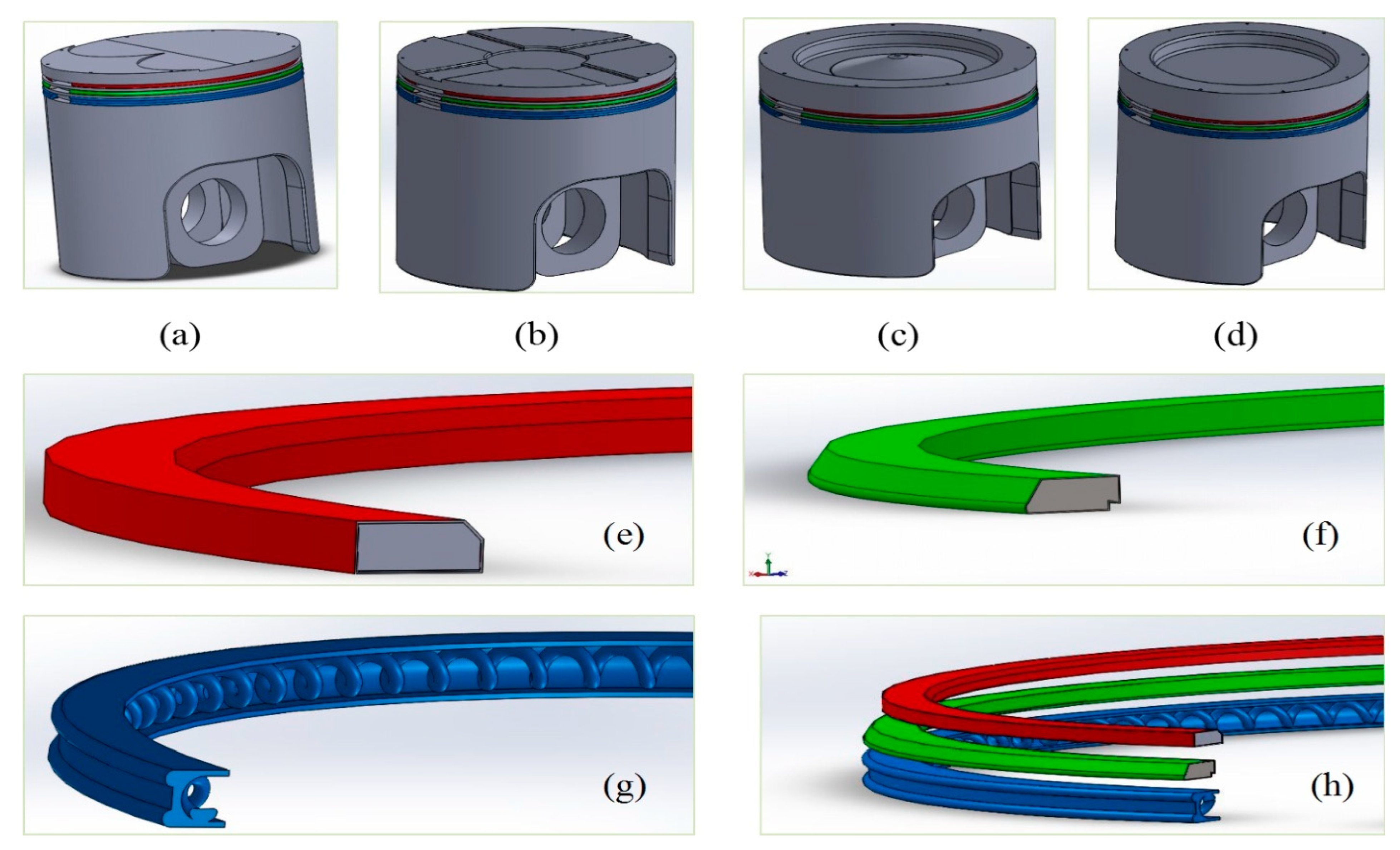
2.2. Solid Modeling for Variable Piston Crown and Ring Geometry

Before proceeding with structural strength analysis, it is necessary to prepare the solid model of all constituent components of the piston subsystem using CATIA. The layout drawing for each case was first prepared prior to converting the same to the 3D model of desired dimensions, clearance, and tolerances. Figure 1a–d shows the 3D model of type-A, type-B, type-C, and type-D crowns, respectively. The aim of ‘giving variable crown’ is to create different clearance volumes for the combustion chamber at the TDC location for improved clearance volume that helps in better combustion and power. The model contains suitable ring grooves and other details, as specified in commercially available pistons. The orifice provision is given on the crown to allow gas to enter the back of the first ring to create pressure. Figure 1e–h present the coated solid models of the compression ring, scraper ring, oil control ring, and total ring assembly, which are the essential design for finite element analysis. The details of the material parameters, such as volume (mm3) and mass (kg) required for the finite element analysis, are now given in Table 1.
The further requirement of the FEA is to create discrete models by creating the mesh wires of the piston assemblies under investigation. The details of the mesh characteristics, such as number of elements, number of nodes, transition ratio, minimum edge length, and growth, are presented in Table 2. The reason for the variation of such parameters is due to dimensional difference of the model out of different piston design considerations. Figure 2 shows the meshed models of compression ring (a), scraper ring (b), oil control ring (c), and assembled rings with the relative location (d) with stated mesh characteristics. The core and coating are quantified in the model through different material properties. The details of material for different components are given in Table 3. The piston, upper compression ring (UCR), scraper ring (SR), and oil control ring (OCR) core materials are chosen to be structural steel, whereas the rings are considered to be coated with Nickasil, TiSiCN thin film, as it provides an excellent adhesion bonding in reciprocating components in contact such as piston ring, thereby inducing corrosion resistant and wear resistance of the coated-components.
TiSiCN coating is a high-performance coating that has gained popularity in various industrial applications due to its unique properties. The motivation for selecting TiSiCN coating could vary depending on the specific application and requirements, but some common reasons include the following.
  • High-temperature resistance: TiSiCN coating can withstand high temperatures up to 1200 °C, making it an excellent choice for applications that involve high-temperature environments.
  • Wear and corrosion resistance: TiSiCN coating exhibits excellent wear and corrosion resistance properties, making it ideal for applications that involve abrasive and corrosive environments.
  • High hardness: TiSiCN coating has a high hardness of up to 40 GPa, making it suitable for applications that require high wear resistance and durability.
  • Low friction coefficient: TiSiCN coating has a low friction coefficient, which makes it ideal for applications that require reduced friction and wear.
Overall, the motivation for selecting TiSiCN coating would be to enhance the performance and durability of components or tools in various industrial applications. The coating layer of 5 µm in case all rings are considered in the simulation. They are implanted through PVD/CVD for analysis.
To characterize a thin coating in a Finite Element Model (FEM), the following steps can be taken.
  • Material properties: The material properties of the coating need to be defined, including its thickness, density, elastic modulus, Poisson’s ratio, and other relevant mechanical properties. These properties can be obtained from experimental data or literature review.
  • Mesh generation: A suitable mesh must be generated to accurately represent the coating’s geometry and thickness. The mesh should be fine enough to capture the coating’s behavior but not too fine, as it may increase the computational cost.
  • Interface elements: Interface elements need to be defined to connect the coating to the substrate. Interface elements are used to model the adhesion behavior between the coating and substrate.
  • Boundary conditions: Appropriate boundary conditions need to be defined to simulate the coating’s behavior under the given loading conditions. These boundary conditions may include applied loads, temperature changes, and other environmental factors.
  • Verification: Once the FEM has been developed, it should be verified by comparing its results with experimental data or analytical solutions. This process helps to ensure that the FEM accurately represents the coating’s behavior under different loading conditions.
  • Overall, characterizing a thin coating in an FEM requires careful consideration of the coating’s material properties, mesh generation, interface elements, boundary conditions, and verification methods. By following these steps, it is possible to develop an accurate FEM that can be used to study the coating’s behavior under different conditions.

2.3. TiSiCN Coating of Piston Ring

TiSiCN coating can be produced on ring surface through plasma-enhanced chemical vapor deposition technique [20,43]. Components produced through such coating techniques show high hardness (up to 50 MPa) and good wear resistance. Therefore, they are most suitable for high-temperature tribological applications such as piston ring–cylinder liner co-action. Such coating technique involves the method of growing nanocomposite film on substrate surface through complete controlled deposition. The deposition is faster compared to sputter deposition or thermal/electron beam evaporation [43,44,45,46].

2.4. Meshing of Piston Subsystem Components

It is necessary to develop the mesh model of the piston subsystem components for structural analysis. The meshing is conducted using Ansys workbench. The steps include importing the CAD model of subcomponents developed in CATIA to hyper mesh and repairing for refinement. The model files are stored in .stp or .iges format. There is need for free edges and duplicating surfaces. The surface is subjected to trimming with proper tolerance.

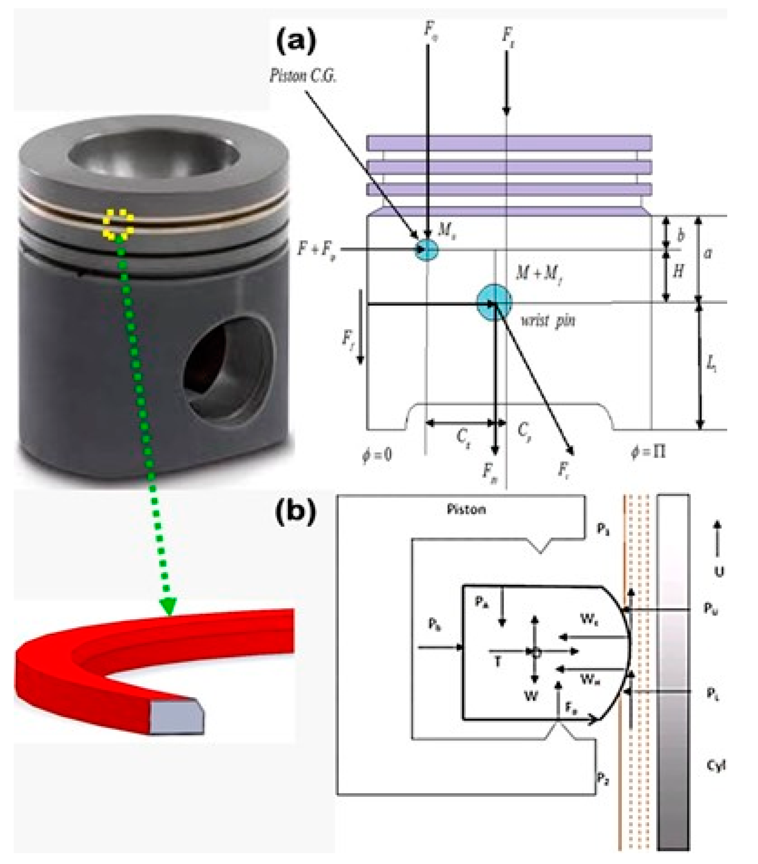
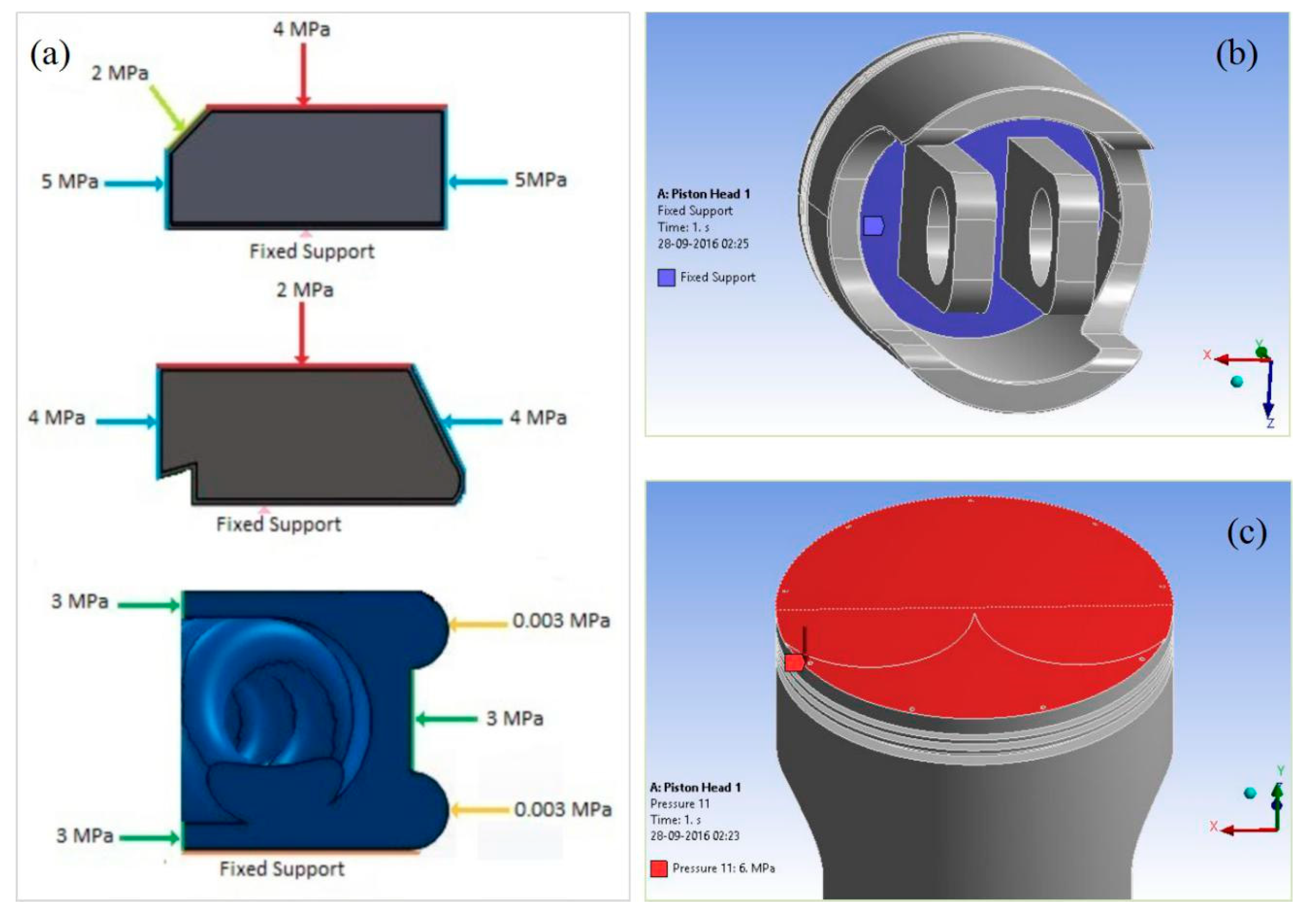
2.5. Loading Conditions in a Dynamic Piston Assembly and the Forces Affecting the FEA

In order to find out the forces and dynamic parameters involved in the piston subsystem components, it is necessary to know the theoretical or analytic basis on which the evaluation of such force involves so that later, these parameters can be regulated for improving strength. Figure 3a,b shows the all-possible forces acting on a piston block and dynamic ring, which include inertial forces caused due to primary/reciprocating motion, inertial force caused due to secondary motion, gas dynamics force, lubricant reaction, friction force, and ring elastic forces.
The forces involved due to elastohydrodynamic action are estimated by solving Reynolds equation, energy equation, and rheological equation simultaneously as per Mishra [9] and Mishra et al. [16,25,29]. It also addresses the asperity contact issue through Greenwood and Tripp model for boundary co-action [47]. The tribodynamic forces are linked to the elastodynamic model for further analysis as part of correlation. The ring pack elastohydrodynamic follows the elastodynamic correlation of compression rings by Biswal and Mishra [38]. However, for subsequent rings, they are considered with reduced gas pressure and specific geometry.
Figure 4a–i address the cyclic variation of piston tribodynamic parameters. In Figure 4a, the cyclic variation of combustion chamber pressure is presented. It is significant during compression and power stroke transition [25]. The highest being 120 MPa at power stroke (273° crank location). The total piston subsystem friction is presented in Figure 4b. The sign of the friction force changes due to change in direction at each stroke. Parameters such as top and bottom eccentricities and lateral tilt, as given in Figure 4c,f,e, control the cyclic variation of inertia forces due to secondary motion. The force due to hydrodynamic action largely depends on the film of the conjunctions. Figure 4g shows the skirt-liner film at various rpm. The friction force (Figure 4h) is of maximum 70 N during power stroke resulting near to 1100 W of power loss. The details of forces and their depending parameters are enlisted in Table 4. These parameters are structural as well as fluid flow induced/elastohydrodynamic forces. Hence, in the piston subsystem, the correlational analysis of elastic and elastodynamic parameters can help develop an iteration algorithm to reduce error and implement more realistic and ‘near to experimental evaluation’ of both elastic and elastohydrodynamic variables.

2.6. Boundary Conditions for the Elastodynamics and Elastohydrodynamic Correlation Analysis

The boundary conditions of piston subsystem problems are dynamic in nature, where moving boundaries are implemented for solutions. The initial and final positions of the boundary are assumed to be operated in higher temperature and pressure differences. In the upper-end boundary of the piston, the maximum value of cyclic pressure is 12 MPa, while that of combustion temperature is 450 °C. On the other side, in the lower boundary, pressure and temperature are assumed to be that of crankcase zone pressure and temperature. In reciprocating piston and cylinder systems, reversal of sliding direction is frequent due to rapid alteration of leading and trailing edges [15]. The lubricant entrainment is considered in the x-direction with fully flooded in let boundary [25]. Pressure boundary is influenced by combustion gas pressure, inter-ring gas pressure, and crankcase pressure that creates a moving boundary. It is also influenced by ring residing positions [17,18]. The rings are set on top land of the respective groove at the instant the piston assembly is set to downward motion (suction/power stroke), whereas during upward motion (compression/power stroke), it resides on the bottom lands of the respective grooves. All the information on the forces is given in Figure 3a,b. Due to more influence of other forces acting in piston assembly, effect of cavitating is currently ignored. The exit boundary of contact conditions is considered those of Swift–Stieber, hence: ph(xc,y) = pc and (dph/dx)x=xc = 0.
Here, such boundary fixation decides the position of oil film rupture [25]. Piston is assumed to be pinned in the piston pin bore by gudgeon pin, as given in Figure 5b. For the strength analysis, four different crown geometries are taken for finite element analysis. Compression ring is coated with TiSiCN [25]. The bonding strength between coating and substrate is due to inter-molecular adhesion, and the correlation to interfacial toughness is well adjusted [44,45]. Contact friction due to other contacting regions, such as that due to groove land-ring contact and gudgeon piston bore contact, are assumed to be negligible compared to ring-liner and skirt-liner contact friction. Though there is cyclic variation of forces, we have considered maximum value of all those to evaluate the optimum design stress and strain for the periodic loading. All forces considered working on the ring pack are shown in Figure 5a. Figure 5b shows that the crown is given fixed support for FEA analysis. The gas pressure built up on the top of the piston is pressure-type force as given in Figure 5c. Table 5 shows the mesh convergence test of the FEA model. Through this trial run, the element size is fixed to 1.1 mm with corresponding number of elements generated are 203,121 with 402,605 number of nodes.
Figure 6 gives the tribodynamic information of the piston ring liner lubrication.

2.7. Fluid Structure Interactive Process Diagram

Figure 7 shows the iterative link of elastodynamic and elastohydrodynamic conditions of piston assembly. Such process can be set with some error convergence for interlinking.

3. Results and Discussion

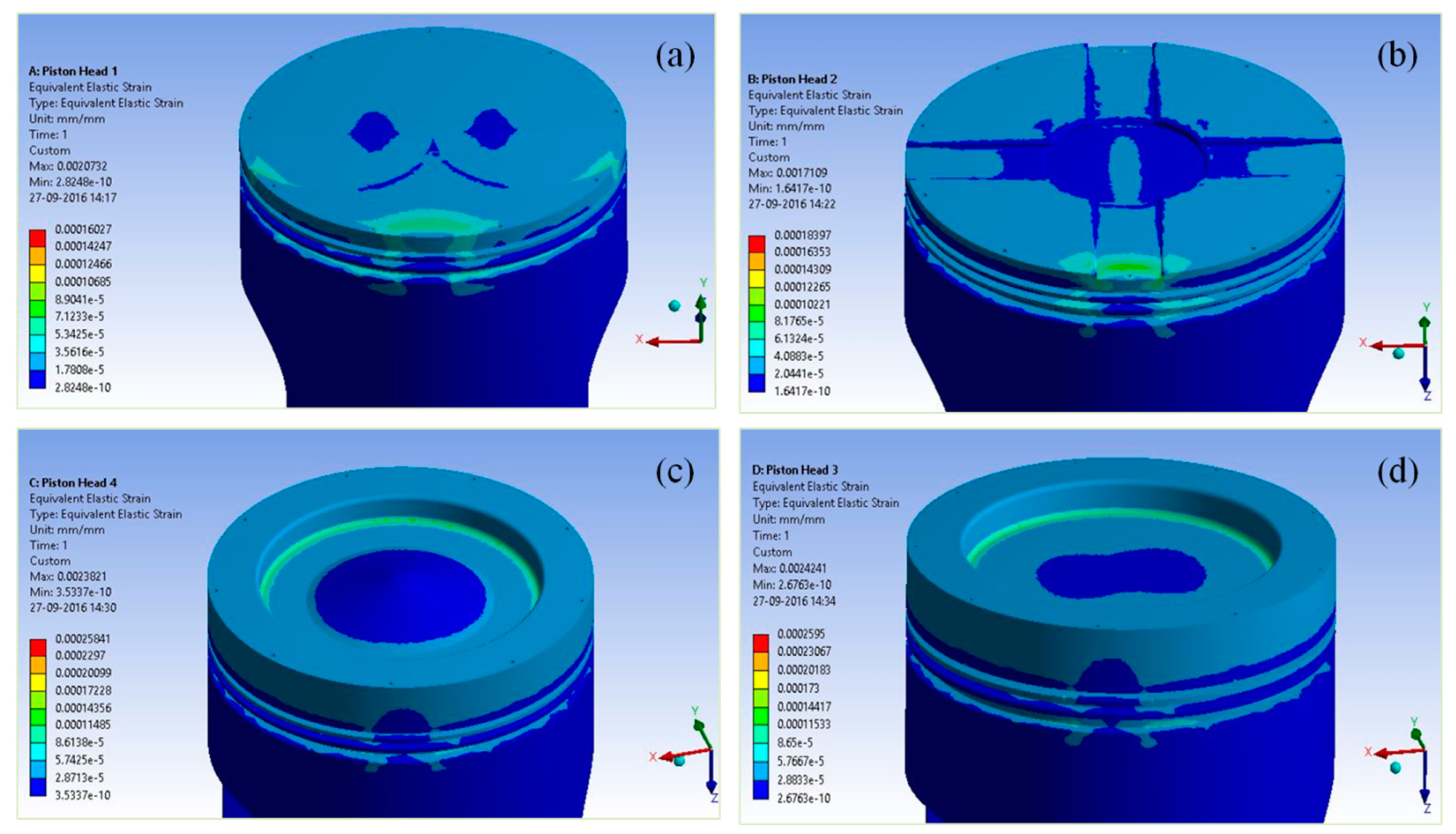
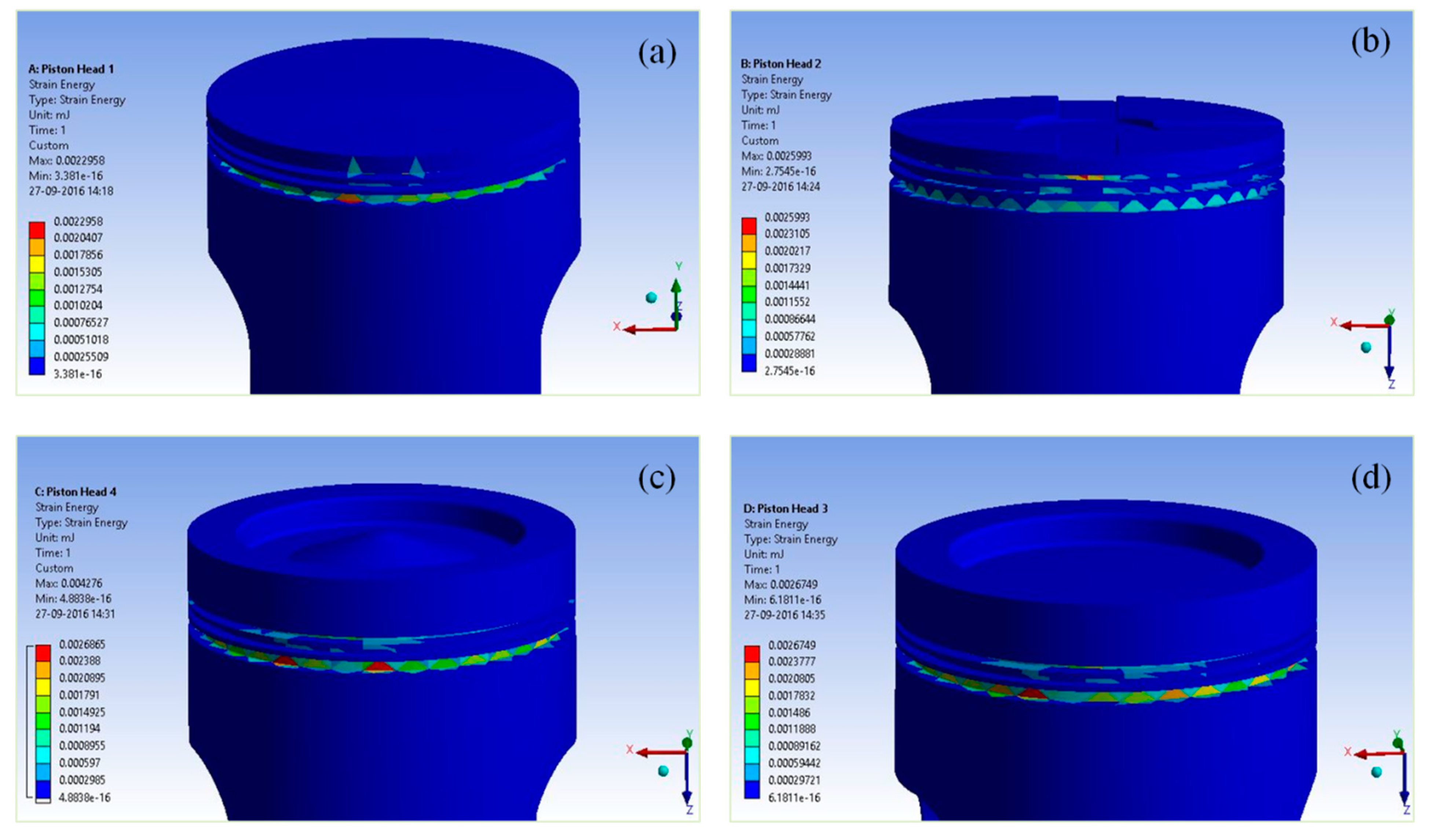
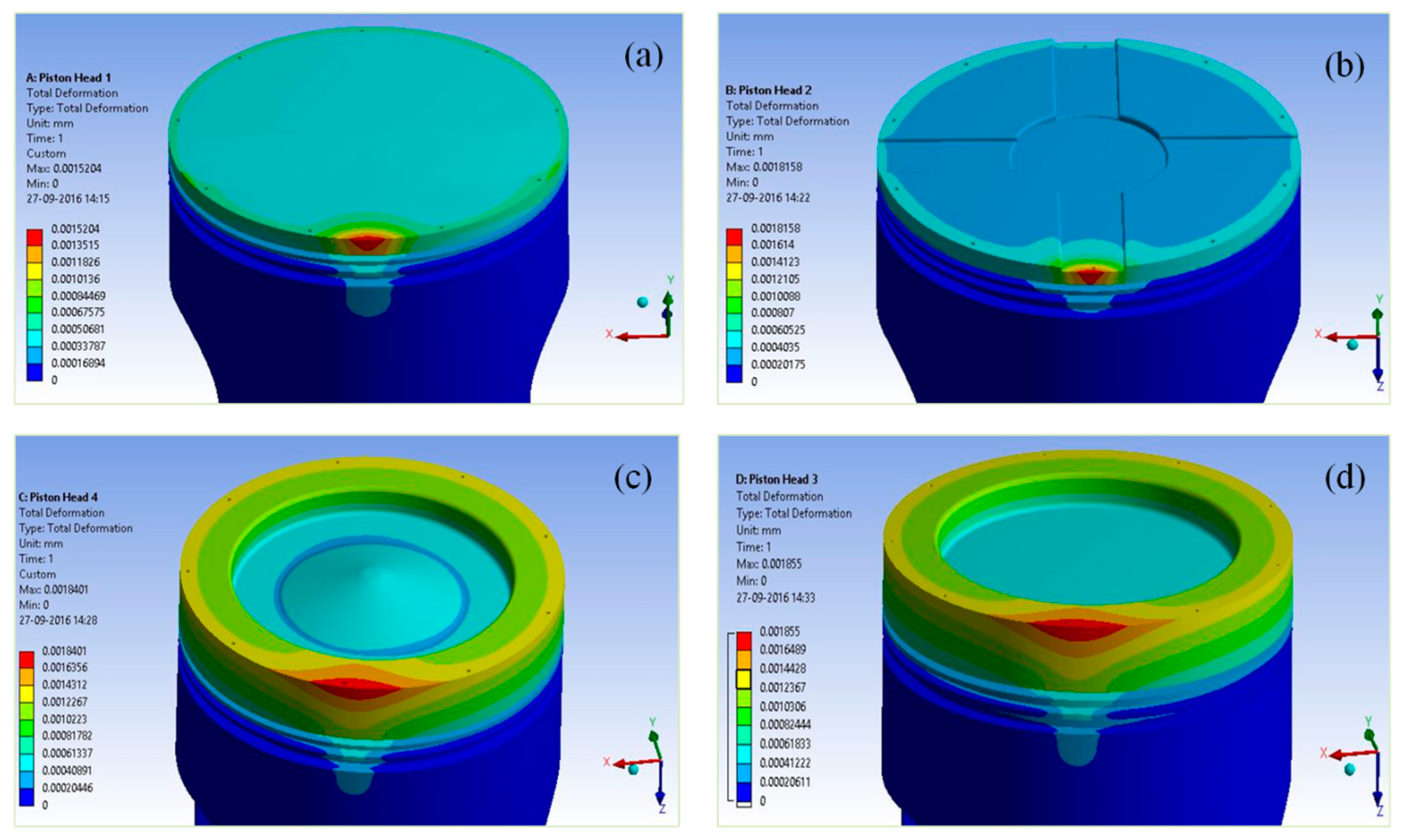
3.1. Structural Strength of Piston with Variable Crown

Piston bodies are subjected to repetitive loading due to cyclic reciprocation. Even within the elastic limit, there may be a fracture of the piston because of the high thermal and stress environment. Designated piston crowns facilitate the necessary clearance volume. Change in crown geometry can modify the control volume in clearance. Such modification affects the combustion dynamics, thereby changing the chamber pressure. For the current analysis, we have chosen four different crown designs to study such changes in piston strength. In the stated load and boundary conditions, Figure 8a–d shows the equivalent elastic strain of the piston for type-A, type-B, type-C, and type-D pistons, respectively. The type-A crown develops a minimum strain of 0.00016, while the type-C and type-D crown are subjected to the maximum elastic strain of 0.0002595. It may be due to the variation in combustion dynamics resulting from crown design modification.
The von Misses stress criterion is most widely used for failure analysis because it is based on maximum principal shear strain energy and is applicable to all types of material. Figure 9 shows the equivalent von Misses stress fringe on the piston surface for considered four different designs. In the stated load and boundary conditions, 31.18/30, 25/36.5, 47/35, and 47/35 are the ratio of coated to the uncoated piston of type-A, B, C, and D von Misses in MPa. Type-B shows a reduction in strength. Figure 10 represents the von Misses strain energy. More energy content is observed in the vicinity of ring grooves near the thrust side of the piston. It is due to numerous forces active in this region during an engine cycle. Figure 11 shows the total deformation for four different designs. With simultaneous action of all forces, the type-A crown shows the least total elastic deformation. The high deformation regions are because of the stress localization at the thrust side top end.

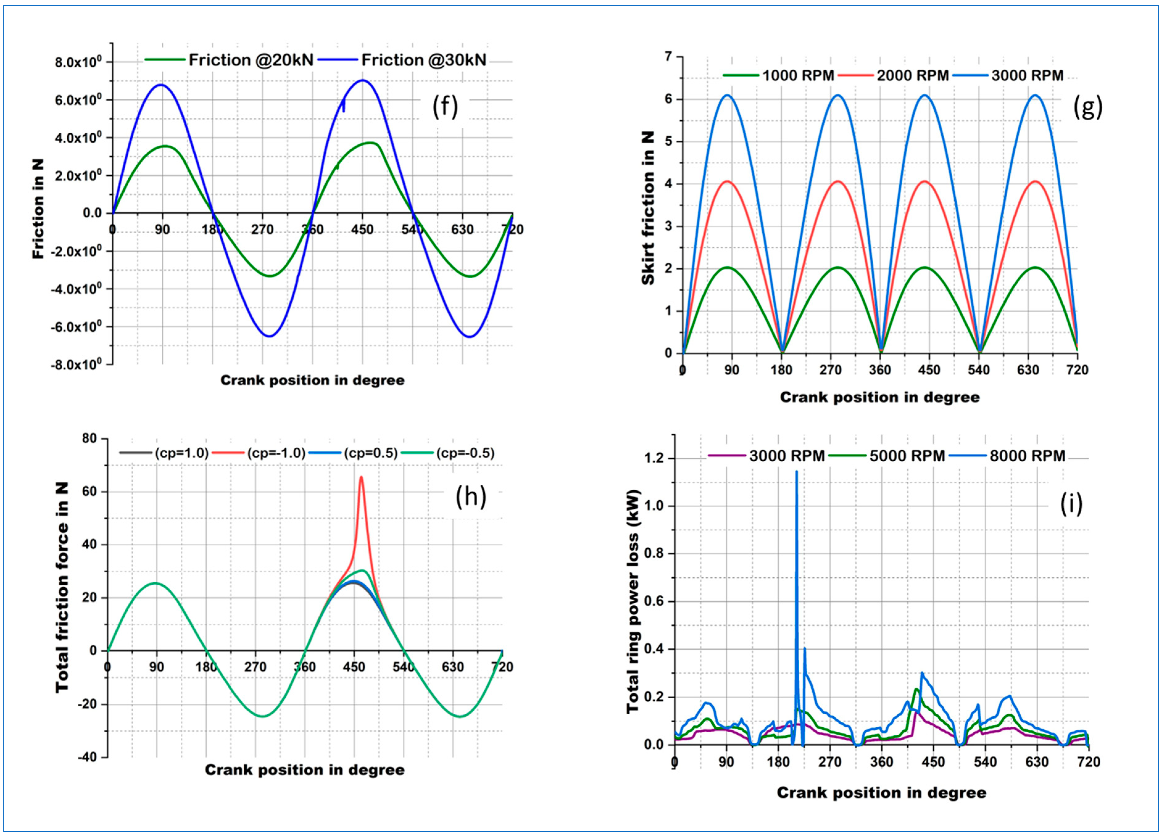
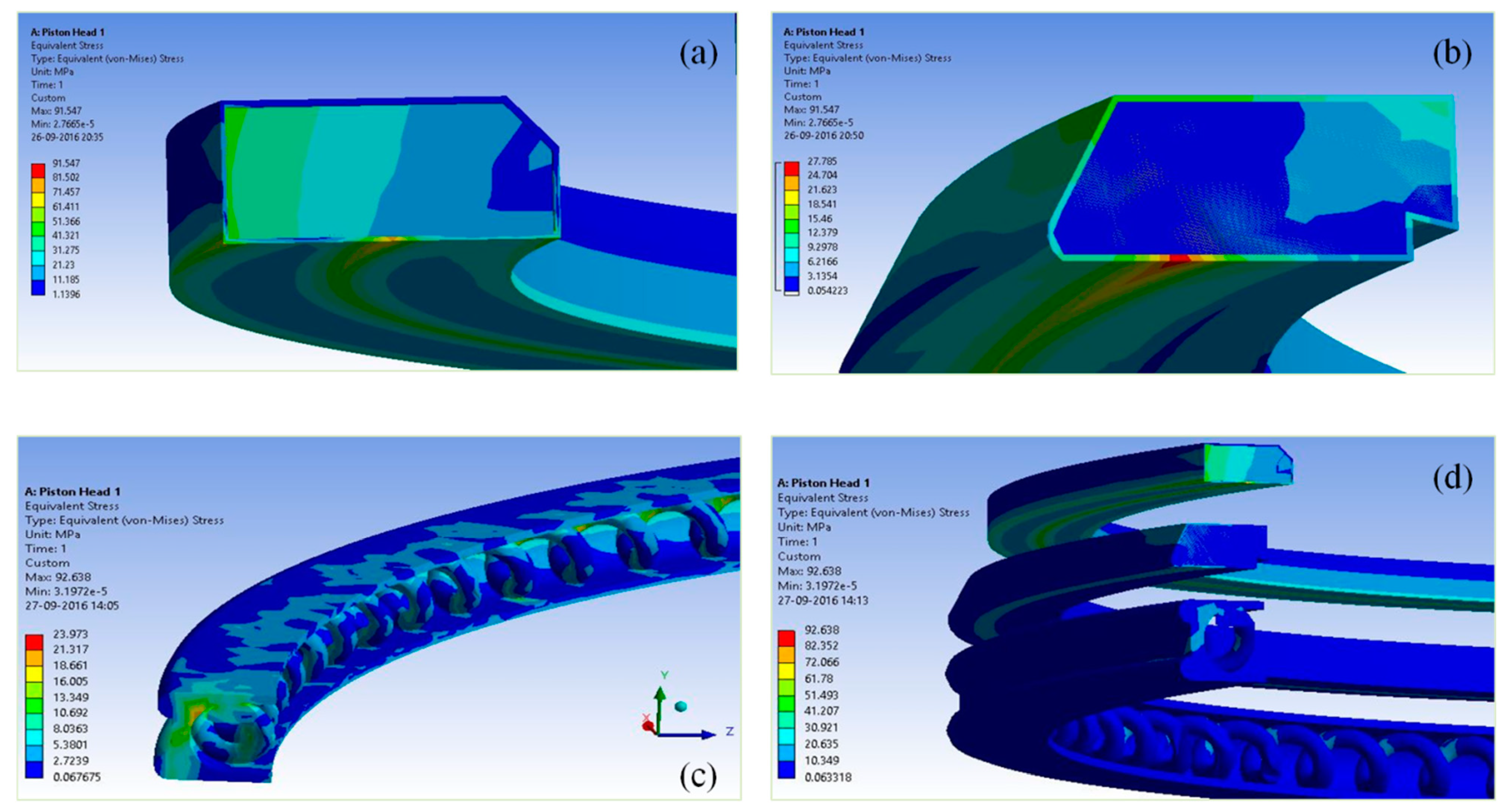
3.2. Structural Strength of Coated Piston Rings

In the piston subsystem, piston rings are in direct contact with the cylinder liner. Direct contact with the piston and liner is avoided to reduce the cost of repair or replacement. Rings because of springing action, go beyond the level of the piston and touch the liner to conform [20]. Even though there is lubrication in contact, there is rapid wear in the ring liner interface out of frequent sliding and mixed lubrication. For enhancing the life of the engine, a highly durable coating is desirable, which can sustain severe temperatures and stress environments.
Figure 12 presents the equivalent elastic strain of the compression ring, scraper ring, oil control ring, and entire ring pack. The compression ring suffers maximum elastic deformation of 0.00203, while the scraper ring with 0.0005 and the oil control ring with 0.0001, respectively. The reason being a few highly influential forces, such as the gas pressure effect diminished beyond the top ring, where inter-ring gas pressures drop rapidly because of proper sealing. Further, Figure 13 represents the von Misses stress in the three different rings and the ring pack. The stress in the case of the compression ring is 92.64 MPa, while 27.7 MPa and 24 MPa for the scraper and oil control ring, respectively. The corresponding total deformations are 0.62 µm, 0.38 µm, and 0.28 µm.

3.3. Summary of Uncoated and Coated Results

In order to understand the effect of coating and the effect of crown design modification, both coated and uncoated subsystem components are simulated. The results thus obtained are presented in Table 6, Table 7, Table 8 and Table 9. The results include the strength parameters for the piston, compression ring, and scraper ring. Furthermore, Figure 14 shows the comparative analysis of stress, elastic deformation, and strain for all the considered cases. Type-D uncoated piston has better strength (50 MPa von Misses). The compression ring fitted in the type-C crown offers the least strength of 80 MPa. While the type-A crown shows the least elastic deformation. Elastic strain is less in the coated ring compared to uncoated ones. Coated ring offers at least 20% less elastic strain compared to uncoated ones because of strong implantation.
Figure 15 shows the comparative analysis of von Misses stress, elastic deformation and elastic strain respectively.

4. Conclusions

For the better life of the engine, it is necessary to replace coated components subjected to contact dynamics. Based on the strength analysis, the following can be predicted: the order of hardness required for a particular application such that an appropriate coating technique would be adopted for the specific cases. In this case, TiSiCN coating is chosen to counter high temperatures and complex loading conditions. The results of the elastodynamic and elastohydrodynamic correlation simulation show some interesting outcomes as follows:
  • Based on the strength analysis, the type-D design is found to be stronger than others because of favorable combustion dynamics due to such a crown shape;
  • There is near to 50% variation in the strength of the compression ring observed due to coated against the uncoated condition. It is because of most force actions near the vicinity of the top ring, mostly combustion pressure force is more active;
  • In most cases, elastic deformation and strain are more for coated components compared to uncoated ones. The compression ring suffers the most in deformation and strain reason being the highest back pressure on it due to its immediate presence in the combustion chamber;
  • Crown design type-A resulted in less stress level because of producing better turbulence due to combustion, hence suggested.
Improved strength parameters have a direct relation to friction modification and lubrication effectiveness. After coating, the selection of suitable geometry can help decide the best design for the piston subsystem. This analysis can help establish green manufacturing of piston components for a more sustainable future engine with enhanced life. The future work in this research area is to add the FTIR characterization data of the fabricated coating on the piston and to carry out a simulation of the adhesive bonding of the core and coating interface along with the future experimental method of nano indention.

Author Contributions

Conceptualization, P.C.M. and A.B.; Methodology, A.R. and S.R.D.; Software, P.C.M., A.R. and A.B.; Validation, P.C.M. and S.R.D.; Formal analysis, A.B., N.S., S.R.D. and A.D.; Resources, N.S. and A.D.; Data curation, P.C.M., N.S. and A.D.; Writing–original draft, P.C.M. and N.S.; Funding acquisition, A.D. All authors have read and agreed to the published version of the manuscript.

Funding

This research received no external funding.

Institutional Review Board Statement

Not applicable.

Informed Consent Statement

Not applicable.

Data Availability Statement

Data is included in the manuscript.

Conflicts of Interest

The authors declare no conflict of interest.

References

  1. Saraeea, H.S.; Jafarmadar, S.; Sayadi, M.; Parikhani, A.; Kheyrollahi, J.; Pourvosoughi, N. Green fuel production from Pistacia Khinjuk and its engine test analysis as a promising alternative. J. Clean. Prod. 2017, 156, 106–113. [Google Scholar] [CrossRef]
  2. Zhang, Y.; Liu, S.; Liu, Y.; Yang, H.; Li, M.; Huisingh, D.; Wang, L. The ‘Internet of Things’ enabled real-time scheduling for remanufacturing of automobile engines. J. Clean. Prod. 2018, 185, 562–575. [Google Scholar] [CrossRef]
  3. Fraccascia, L.; Giannoccaro, I.; Albino, V. Green product development: What does the country product space imply? J. Clean. Prod. 2018, 170, 1077–1088. [Google Scholar] [CrossRef]
  4. Chhabra, D.; Garg, S.; Singh, R.K. Analyzing alternatives for green logistics in an Indian automotive organization: A case study. J. Clean. Prod. 2017, 167, 962–969. [Google Scholar] [CrossRef]
  5. Oncel, S.S. Green energy engineering: Opening a green way for the future. J. Clean. Prod. 2017, 142, 3095–3100. [Google Scholar] [CrossRef]
  6. Reeves, C.J.; Siddaiah, A.; Menezes, P.L. Tribological study of imidazolium and phosphonium ionic liquid-based lubricants as additives in carboxylic acid-based natural oil: Advancements in environmentally friendly lubricants. J. Clean. Prod. 2018, 176, 241–250. [Google Scholar] [CrossRef]
  7. Zareh-Desari, B.; Davoodi, B. Assessing the lubrication performance of vegetable oil-based nano-lubricants for environmentally conscious metal forming processes. J. Clean. Prod. 2016, 135, 1198–1209. [Google Scholar] [CrossRef]
  8. Niketh, S.; Samuel, G. Surface texturing for tribology enhancement and its application on drill tool for the sustainable machining of titanium alloy. J. Clean. Prod. 2017, 167, 253–270. [Google Scholar] [CrossRef]
  9. Mishra, P.C.; Kumar, S. Modeling for Design Optimization of Piston Crown Geometry Through Structural Strength and Lubrication Performance Correlation Analysis. Front. Mech. Eng. 2019, 5, 17. [Google Scholar] [CrossRef]
  10. Baker, A.; Gazzard, S. Developments in materials for pistons. Mater. Des. 1988, 9, 28–33. [Google Scholar] [CrossRef]
  11. Carvalho, O.; Buciumeanu, M.; Madeira, S.; Soares, D.; Silva, F.; Miranda, G. Optimization of AlSi–CNTs functionally graded material composites for engine piston rings. Mater. Des. 2015, 80, 163–173. [Google Scholar] [CrossRef]
  12. Arsha, A.; Jayakumar, E.; Rajan, T.; Antony, V.; Pai, B. Design and fabrication of functionally graded in-situ aluminium composites for automotive pistons. Mater. Des. 2015, 88, 1201–1209. [Google Scholar] [CrossRef]
  13. Hazar, H. Characterization of MoN coatings for pistons in a diesel engine. Mater. Des. 2010, 31, 624–627. [Google Scholar] [CrossRef]
  14. Zhang, P.; Liu, Z. On sustainable manufacturing of Cr-Ni alloy coatings by laser cladding and high-efficiency turning process chain and consequent corrosion resistance. J. Clean. Prod. 2017, 161, 676–687. [Google Scholar] [CrossRef]
  15. Holmberg, K.; Andersson, P.; Erdemir, A. Global energy consumption due to friction in passenger cars. Tribol. Int. 2012, 47, 221–234. [Google Scholar] [CrossRef]
  16. Mishra, P.C. Modeling the root causes of engine friction loss: Transient elastohydrodynamics of a piston subsystem and cylinder liner lubricated contact. Appl. Math Model 2015, 39, 2234–2260. [Google Scholar] [CrossRef]
  17. Shahmohamadi, H.; Rahmani, R.; Rahnejat, H.; Garner, C.P.; King, P.D. Thermo-Mixed Hydrodynamics of Piston Compression Ring Conjunction. Tribol. Lett. 2013, 51, 323–340. [Google Scholar] [CrossRef]
  18. Liu, K.; Xie, Y.B.; Gui, C.L. A comprehensive study of the friction and dynamic motion of the piston assembly. Proc. Inst. Mech. Eng. Part J J. Eng. Tribol. 1998, 212, 221–226. [Google Scholar] [CrossRef]
  19. Bolander, N.W.; Steenwyk, B.D.; Sadeghi, F.; Gerber, G.R. Lubrication regime transitions at the piston ring-cylinder liner interface. Proc. Inst. Mech. Eng. Part J J. Eng. Tribol. 2005, 219, 19–31. [Google Scholar] [CrossRef]
  20. Ma, M.-T.; Smith, E.H.; Sherrington, I. A Three-Dimensional Analysis of Piston Ring Lubrication Part 1: Modelling. Proc. Inst. Mech. Eng. Part J J. Eng. Tribol. 1995, 209, 1–14. [Google Scholar] [CrossRef]
  21. Ma, S.L.; Ma, D.Y.; Guo, Y.; Xu, B.; Wu, G.Z.; Xu, K.W.; Chu Paul, K. Synthesis and characterization of super hard, self-lubricating Ti–Si–C–N nanocomposite coatings. Acta Mater. 2007, 55, 6350–6355. [Google Scholar] [CrossRef]
  22. Froelund, K.; Schramm, J.; Tian, T.; Wong, V.; Hochgreb, S. Analysis of the piston ring/liner oil film development during warm-up for an SI-Engine. J. Eng. Gas Turb. Power–Trans. ASME 2001, 123, 109–116. [Google Scholar] [CrossRef]
  23. Chong, W.; Howell-Smith, S.; Teodorescu, M.; Vaughan, N. The influence of inter-ring pressures on piston-ring/liner tribological conjunction. Proc. Inst. Mech. Eng. Part J J. Eng. Tribol. 2012, 227, 154–167. [Google Scholar] [CrossRef]
  24. Akalin, O.; Newaz, G.M. Piston ring-cylinder bore friction modeling in mixed lubrication regime: Part I: Analytical results. Trans. ASME J. Tribol. 2001, 123, 211–218. [Google Scholar] [CrossRef]
  25. Mishra, P.C.; Balakrishnan, S.; Rahnejat, H. Tribology of compression ring-to cylinder contact at reversal. Proc. Inst. Mech. Eng. Part J-J. Eng. Tribol. 2008, 222, 815–826. [Google Scholar] [CrossRef]
  26. Usman, A.; Park, C.W. Numerical investigation of frictional behaviour and energy loss in mixed hydrodynamic contact of piston ring pack with deformed cylinder liner during warm up period of SI engine. Energy Conserv. Manag. 2016, 117, 115–131. [Google Scholar] [CrossRef]
  27. Prata, A.T.; Fernandes, J.R.S.; Fagotti, F. Dynamic Analysis of Piston Secondary Motion for Small Reciprocating Compressors. J. Tribol. 2000, 122, 752–760. [Google Scholar] [CrossRef]
  28. Dursunkaya, Z.; Keribar, R.; Ganapathy, V. A Model of Piston Secondary Motion and Elastohydrodynamic Skirt Lubrication. J. Tribol. 1994, 116, 777–785. [Google Scholar] [CrossRef]
  29. Mishra, P.C. Tribodynamic modelling of piston compression ring and cylinder liner conjunction in high pressure zone of engine cycle. Int. J. Adv. Manuf. Technol. 2012, 66, 1075–1085. [Google Scholar] [CrossRef]
  30. Morris, N.; Rahmani, R.; Rahnejat, H.; King, P.D.; Fitzsimons, B. Tribology of piston compression ring conjunction under transient thermal mixed regime of lubrication. Tribol. Int. 2013, 59, 248–258. [Google Scholar] [CrossRef]
  31. Akalin, O.; Newaz, G.M. Piston Ring-Cylinder Bore Friction Modeling in Mixed Lubrication Regime: Part II—Correlation With Bench Test Data. J. Tribol. 1999, 123, 219–223. [Google Scholar] [CrossRef]
  32. Pereira, O.; Martin-Alfonso, J.E.; Rodríguez, A.; Calleja-Ochoa, A.; Fernández-Valdivielso, A.; Lopez de Lacalle, L.N. Sustainability analysis of lubricant oils for minimum quantity lubrication based on their tribo-rheological performance. J. Clean. Prod. 2017, 164, 1419–1429. [Google Scholar] [CrossRef]
  33. Thakur, A.; Gangopadhyay, S. Dry machining of nickel-based super alloy as a sustainable alternative using TiN/TiAlN coated tool. J. Clean. Prod. 2016, 129, 256–269. [Google Scholar] [CrossRef]
  34. Liu, Y.; Li, Y.; Tian, T. Development and Application of Ring-Pack Model Integrating Global and Local Processes. Part 2: Ring-Liner Lubrication. SAE Int. J. Engines 2017, 10, 1969–1983. [Google Scholar] [CrossRef]
  35. Baker, C.; Theodossiades, S.; Rahmani, R.; Rahnejat, H.; Fitzsimons, B. On the Transient Three-Dimensional Tribodynamics of Internal Combustion Engine Top Compression Ring. J. Eng. Gas Turbines Power 2017, 139, 062801. [Google Scholar] [CrossRef]
  36. Durat, M.; Kapsiz, M.; Nart, E.; Ficici, F.; Parlak, A. The effects of coating materials in spark ignition engine design. Mater. Des. 2012, 36, 540–545. [Google Scholar] [CrossRef]
  37. Öner, C.; Hazar, H.; Nursoy, M. Surface properties of CrN coated engine cylinders. Mater. Des. 2009, 30, 914–920. [Google Scholar] [CrossRef]
  38. Biswal, S.; Mishra, P.C. Piston Compression Ring Elastodynamics and Ring–Liner Elastohydrodynamic Lubrication Correlation Analysis. Lubricants 2022, 10, 356. [Google Scholar] [CrossRef]
  39. Lin, J.; Wei, R.; Bitsis, D.C.; Lee, P.M. Development and evaluation of low friction TiSiCN nano composite coatings for piston ring applications. Surf. Coat. 2016, 298, 121–131. [Google Scholar] [CrossRef]
  40. Shypylenko, A.; Pshyk, A.; Grześkowiak, B.; Medjanik, K.; Peplinska, B.; Oyoshi, K.; Pogrebnjak, A.; Jurga, S.; Coy, E. Effect of ion implantation on the physical and mechanical properties of Ti-Si-N multifunctional coatings for biomedical applications. Mater. Des. 2016, 110, 821–829. [Google Scholar] [CrossRef]
  41. Abd, A.M.; Rahman, E.I.; Wei, R. A comparative study of conventional magnetron sputter deposited and plasma enhanced magnetron sputter deposited Ti–Si–C–N nanocomposite coatings. Surf. Coat. Technol. 2014, 258, 320–328. [Google Scholar]
  42. Morris, N.; Mohammadpour, M.; Rahmani, R.; Johns-Rahnejat, P.M.; Rahnejat, H.; Dowson, D. Effect of cylinder deactivation on tribological performance of piston compression ring and connecting rod bearing. Tribol. Int. 2018, 120, 243–254. [Google Scholar] [CrossRef]
  43. Guo, Y.; Shengli, M.; Xuand, K.; Bell, T. The nanostructured phase transition of superhard Ti–Si–C–N coatings. Nanotechnology 2008, 19, 215603. [Google Scholar] [CrossRef]
  44. Hadad, M.; Marot, G.; Démarécaux, P.; Chicot, D.; Lesage, J.; Rohr, L.; Siegmann, S. Adhesion tests for thermal spray coatings: Correlation of bond strength and interfacial toughness. Surf. Eng. 2007, 23, 279–283. [Google Scholar] [CrossRef]
  45. Di, Y.; Cai, Z.; Zhang, P. The Tribological Performance of CrMoN/MoS2 Solid Lubrication Coating on a Piston Ring. Lubricants 2017, 5, 13. [Google Scholar] [CrossRef]
  46. Wang, H.; Ou, Y.; Zhang, X.; Liao, B.; Ou, X.; Luo, J.; Pang, P.; Chen, L.; Hua, Q.; Bao, M. Tribocorrosion behaviors of TiSiCN nanocomposite coatings deposited by high power impulse magnetron sputtering. Mater. Res. Express 2020, 7, 076407. [Google Scholar] [CrossRef]
  47. Greenwood, J.A.; Tripp, J.H. The Contact of Two Nominally Flat Rough Surfaces. Proc. Inst. Mech. Eng. 1970, 185, 625–633. [Google Scholar] [CrossRef]
Figure 1. Solid models of piston assembly with different crown designs (a) type-A crown, (b) type-B crown, (c) type-C crown, (d) type-D crown, (e) coated compression ring, (f) coated scraper ring, (g) coated oil control ring, and (h) piston ring pack 3D relative location.
Lubricants 11 00192 g001
Figure 2. Mesh models of piston assembly with different crown designs (a) type-A crown, (b) type-B crown, (c) type-C crown, (d) type-D crown, (e) coated compression ring, (f) coated scraper ring, (g) coated oil control ring, and (h) piston ring pack 3D relative location.
Lubricants 11 00192 g002
Figure 3. (a) Free body diagram of piston subsystem [25] and (b) free body diagram of coated piston ring.
Lubricants 11 00192 g003
Figure 4. (a,b) Tribodynamic parameters for elastodynamic and elastohydrodynamic correlation(set_1): (a) combustion gas pressure (MPa) and (b) friction force (N) due to ring-liner co-action. (ce) Tribodynamic parameters for elastodynamic and elastohydrodynamic correlation (set_2): (c) top eccentricity (et) (m) for different loading, (d) bottom eccentricity (eb) (m), and (e) angle of twist (rad). (fi) Tribodynamic parameters for elastodynamic and elastohydrodynamic correlation(set_3): (f) friction force (N) due to due to skirt-liner co-action, (g) skirt-liner conjunction film thickness (μm), (h) friction force (N) due to ring-liner co-action, and (i) total ring power loss (kW) of the whole ring pack.
Lubricants 11 00192 g004aLubricants 11 00192 g004b
Figure 5. Load and boundary conditions. (a) Loading conditions in different rings, (b) bottom hinge support, and (c) top gas pressure loading.
Lubricants 11 00192 g005
Figure 6. Tribodynamic information: (a) quantification of geometry of bore irregularity in 2nd order bore, (b) 4th order bore, (c) 8th order bore, (d) measurement of irregular bore, (eg) 3D film at a crank location in suction, compression, power, and exhaust, (h) maximum 3D asperity contact pressure, (i) maximum viscosity variation in 3D, (j) maximum lubricant temperature in contour form, (k) total shear rate due hydrodynamic and asperity contact action, (l) liner roughness pattern, and (m) deep valley and smooth top formation due to double honing.
Lubricants 11 00192 g006
Figure 7. Fluid structure interactive simulation process diagram for piston assembly elastodynamics and elastohydrodynamic correlation.
Lubricants 11 00192 g007
Figure 8. Equivalent elastic strain of (a) type-A crown, (b) type-B crown, (c) type-C crown, and (d) type-D crown.
Lubricants 11 00192 g008
Figure 9. Equivalent von Misses stress of (a) type-A crown, (b) type-B crown, (c) type-C crown, and (d) type-D crown.
Lubricants 11 00192 g009
Figure 10. Strain energy of (a) type-A crown, (b) type-B crown, (c) type-C crown, and (d) type-D crown.
Lubricants 11 00192 g010
Figure 11. Total deformation in piston of (a) type-A crown, (b) type-B crown, (c) type-C crown, and (d) type-D crown.
Lubricants 11 00192 g011
Figure 12. Equivalent elastic strain of different rings: (a) coated compression ring, (b) coated scraper ring, (c) coated oil control ring, and (d) piston ring pack 3D relative location.
Lubricants 11 00192 g012
Figure 13. Equivalent von Misses stress of different rings: (a) coated compression ring, (b) coated scraper ring, (c) coated oil control ring, and (d) piston ring pack 3D relative location.
Lubricants 11 00192 g013
Figure 14. Total deformation of different rings: (a) coated compression ring, (b) coated scraper ring, (c) coated oil control ring, and (d) piston ring pack 3D relative location.
Lubricants 11 00192 g014
Figure 15. Comparative analysis of von Misses stress (v1–v4), total elastic deformation (d1–d4), and elastic strain (e1–e4).
Lubricants 11 00192 g015
Table 1. Design specification (volume and mass) of subsystem components.
DesignVolume (in mm3)Mass (in kg)
Piston assembly using type-A crown1.8737 × 1051.463
Piston assembly using type-B crown1.8572 ×1051.4501
Piston assembly using type-C crown2.1603 × 1051.688
Piston assembly using type-D crown2.1328 × 1051.6665
Table 2. Details of meshing information of the piston assembly.
DesignNo. of ElementsNo. of NodesTransition RatioMinm Edge Length (in mm)Growth Rate
Piston crown type-A 239,158467,9480.2728.3561 × 10−21.2
Piston crown type-B245,079478,7030.2728.3561 × 10−21.2
Piston crown type-C262,226506,9050.2728.3561 × 10−21.2
Piston crown type-D261,052505,6470.2728.3561 × 10−21.2
Table 3. Material details of piston assembly components.
Sl No.ComponentMaterialYoungs Modulus, E (N/mm2)Poisson’s Ratio, υ
1Piston with crown design—A, B, C, DStructural steel2.09 × 1090.3
2 Compression ring Scraper Ring Oil control ring Core Structural steel2.09 × 1090.3
3 Compression ring Scraper Ring Oil control ring Coat TiSiCN (Nikasil)0.5 × 1090.2
Table 4. Details of forces working in piston assembly.
Sl. No.Force ComponentGoverning ParametersFormulationMethod of Evaluation
1Gas dynamics forceAir fuel mixture, cylinder temperature, fuel type, etc.Experimental methodExperimental [6]
2Piston body inertial force (pin and piston) due to primary/reciprocating motion.Piston mass, pin mass, primary reciprocation velocity/acceleration, crank location.Numerical method through iterative algorithm.Finite difference method
3Piston body inertial force (pin and piston) due to secondary motion.Piston mass, pin mass, secondary velocity/acceleration due to lateral tilting of the piston, crank location.Numerical method through iterative algorithmFinite difference method
4Lubricant reaction forceOil film, oil rheological parameters, contact surface roughness, sliding/rolling velocity.Numerical method using iterative algorithm through pressure error convergence, load convergence through film relaxationFinite difference method
5Lubricant friction forceFilm parameter, asperity density, asperity tip radius, surface roughness.Numerical method using iterative algorithm through pressure error convergence, load convergence through film relaxation.Finite difference method
6Asperity contact forceFilm parameter, asperity density, asperity tip radius, surface roughness.Using a subroutine to the original code for lubricated contact analysis.Finite difference method
7Force due to asperity contact frictionFilm parameter, asperity density, asperity tip radius, surface roughness.Using a subroutine to the original code for lubricated contact analysis.Numerical method through computer coding
8Force due to ring elastic strengthRing elasticity, ring geometry, tangential force.Using a subroutine to the original code for lubricated contact analysis.Numerical method through computer coding
9Connecting rod forceOscillatory dynamics of connecting rod, mass of connectingUsing a subroutine to the original code for lubricated contact analysis of skirt-liner contact.Numerical method through computer coding.
Table 5. Mesh convergence test.
SL. No.Element Size (in mm)No of NodesNo. of ElementsMax/Min von Misses Stress (in MPa)Max/Min Deformation (in mm)
11467,948239,158(92.638/3.1972) × 10−50.00152/0
21.1402,605203,121(174.06/2.1519) × 10−50.0016017/0
31.2343,983173,757(121.91/1.9541) × 10−50.001625/0
41.3304,700153,617(111.89/1.2521) × 10−50.001429/0
51.4279,002139,987(174.65/2.3835) × 10−50.001495/0
Table 6. Summary of results (von Misses stress in MPa) for uncoated piston subsystem.
σvon misses (Max)
Assembly 1
σvon misses (Max)
Assembly 2
σvon misses (Max)
Assembly 3
σvon misses (Max)
Assembly 4
σvon misses (Min)
Assembly 1
σvon misses (Min)
Assembly 2
σvon misses (Min)
Assembly 3
σvon misses (Min)
Assembly 4
Piston30.4625.27635.11735.5251.52 × 10−52.7371 × 10−53.8781 × 10−55.277 × 10⁻⁵
Compression ring101.1742.49253.11149.3521.43771.4220.435080.42835
Scraper ring29.09577.99148.26139.9031.34930.0378660.556470.55153
Oil ring21.63721.88831.73332.1080.089960.0716760.0379850.040564
Table 7. Summary of results (maximum deformation in mm and strain) for uncoated piston subsystem.
ΔMax
Assembly 1
ΔMax
Assembly 2
ΔMax
Assembly 3
ΔMax
Assembly 4
εmax
Assembly 1
εmax
Assembly 2
εmax
Assembly 3
εmax
Assembly 4
Piston1.48872 × 10−32.28785 × 10−32.4355 × 10−32.449 × 10−32.04953 × 10−41.54999 × 10−41.7867 × 10−42.449 × 10⁻⁴
Compression ring5.38947 × 10−45.04377 × 10−46.22698 × 10−46.40207 × 10−49.69604 × 10−44.42675 × 10−45.82993 × 10−46.40207 × 10⁻⁵
Scraper ring2.69453 × 10−42.39789 × 10−43.89758 × 10−44.03378 × 10−42.54789 × 10−44.84848 × 10−43.44125 × 10−44.03378 × 10⁻⁴
Oil ring2.57333 × 10−42.58764 × 10−43.75095 × 10−43.81418 × 10−41.45373 × 10−41.46930 × 10−42.07970 × 10−43.81418 × 10⁻⁴
Table 8. Summary of results (von Misses stress in MPa) for coated piston subsystem.
σvon misses(Max)
Assembly 1
σvon misses (Max)
Assembly 2
σvon misses (Max)
Assembly 3
σvon misses (Max)
Assembly 4
σvon misses (Min)
Assembly 1
σvon misses (Min)
Assembly 2
σvon misses (Min)
Assembly 3
σvon misses (Min)
Assembly 4
Piston31.1836.67947.10347.0163.1972 × 10−52.7371 × 10−51.6893 × 10−53.2901 × 10⁻⁵
Compression ring92.63885.063101.97103.641.12041.4221.79011.8117
Scraper ring28.51927.20834.20534.7580.0633180.0378660.0566510.075169
Oil ring23.97324.25529.09630.1920.0676750.0716760.0566850.096292
Table 9. Summary of results (maximum deformation in mm and strain) for coated piston subsystem.
ΔMax
Assembly 1
ΔMax
Assembly 2
ΔMax
Assembly 3
ΔMax
Assembly 4
εmax
Assembly 1
εmax
Assembly 2
εmax
Assembly 3
εmax
Assembly 4
Piston1.52043 × 10−31.86241 × 10−31.8401 × 10−31.85499 × 10−30.0001602730.0001859980.0002584130.00025949
Compression ring6.25745 × 10−46.04565 × 10−47.15219 × 10−47.22795 × 10−40.002073210.00199080.002383050.0024241
Scraper ring3.53936 × 10−43.34378 × 10−44.22744 × 10−44.34028 × 10−40.0005929470.0005752320.0006786070.000692927
Oil ring2.86537 × 10−42.75348 × 10−43.45923 × 10−43.52729 × 10−40.0001623250.0001625260.000196850.000202129
Disclaimer/Publisher’s Note: The statements, opinions and data contained in all publications are solely those of the individual author(s) and contributor(s) and not of MDPI and/or the editor(s). MDPI and/or the editor(s) disclaim responsibility for any injury to people or property resulting from any ideas, methods, instructions or products referred to in the content.

