Abstract
Aiming at the impact of bearing bushes on the lubrication and friction and wear of diesel engine connecting rod big-end bearings, a certain type of diesel engine connecting rod big-end bearing bush was taken as the research object and a multi-body dynamics numerical calculation model of the connecting rod group was built. The connecting rod big-end bearing bushes with four profiles: exponential, hyperelliptic, barrel and trapezoid were used to study the effect on bearing lubrication. The study found that the hyperelliptic bush has the best lubrication performance for the connecting rod big-end bearing. On the basis of the hyperelliptic bush, the bearing clearance, bearing width, journal oil hole diameter and oil supply pressure are used as design variables, using the Box–Behnken experimental design and radial basis function (RBF) neural network method to construct an approximate multi-objective model, which the minimum oil film thickness (abbreviated as MOFT) and average rough contact effective pressure are the objectives. A non-dominated sorting genetic algorithm (NSGA-II) is used for multi-objective optimization. The optimization results show that the bearing clearance remains basically unchanged, the bearing width, journal oil hole diameter and oil supply pressure increase, so that MOFT of the connecting rod big-end bearing rises from 1.56 μm to 1.97 μm, and the average rough contact effective pressure increases from 3.97 MPa decreases to 0.25 MPa. The research results can provide a reference for the analysis and optimization of the lubrication performance of the connecting rod big-end bearing.
1. Introduction
Diesel engines are facing stringent design challenges such as high power density and high torque. These demands impose strict requirements for sliding bearing design and manufacturing. The connecting rod big-end bearing is a sliding bearing subject to high-speed rotation, complex alternating loads produced by the in-cylinder pressure, and reciprocating forces. Lubricant oil film rupture and poor lubrication are prone to occur, resulting in friction and wear, even seizure and pitting [1].
Domestic and foreign studies in recent years on lubrication characteristics of connecting rod bearings of internal combustion engines mainly focused on the “macroscopic” structure of bearings (e.g., oil holes, grooves, and oil storage pools between the bearing bush and the journal), bearing clearance, viscosity-temperature characteristics of lubricant oil, surface roughness, and assembly errors [2,3,4,5].
He et al. studied bearing clearances and oil holes to evaluate bearing performance and used a bi-orthogonal method, a stepwise regression model, and a support vector machine model to predict and optimize the surface roughness contact of a connecting rod bearing [6].
Lavie et al. conducted elastohydrodynamic lubrication and multi-body dynamics analyses of connecting rod bearings and used the design of experiments (DoE), surrogate models, and optimization algorithms to improve bearing lubrication performance [7].
Bi et al. used the thermal elastic hydrodynamic lubrication and the asperity contact theory and analyzed the influences of bearing surface roughness and bearing radial clearance on the lubrication characteristics of connecting rod small-end bearings [8].
Wu et al. used multi-body dynamics to analyze the vertical loads, oil film pressure, and journal orbit trajectories of big-end and small-end bearings of connecting rods in a two stroke marine diesel engine [9].
Ruan et al. studied how the roughness of the contact edge affects both ends of a connecting rod big-end bearing caused by the expansion stroke of engine. They adjusted the geometric bearing profile according to the deformation of the bearing’s inner hole as an input boundary condition [10].
Zhang et al. proposed a geometric design structure for a U-shaped connecting rod big-end bearing for profile designs of the journal and the bush. Their results showed that the new structure could improve lubrication performance compared with the traditional bearing design [11].
Bernhauser et al. used the non-circular bearing shapes in turbocharger structures and found that non-circular bearing shapes are an effective measure to reduce or even prevent self-excited tonal noise [12].
Offner et al. presented a generic friction modeling approach for radial slider bearings to be applied to lubricated contact regimes, which was considered the viscous friction and the particular boundary friction approach. Furthermore, the friction reduction effects of a connecting rod big end using the AlSn-based and polymer-coated bearing shells were analyzed and compared running-in behavior and thermal load capabilities [13].
Razavykia et al. used a hydrodynamic lubrication model to evaluate the tribological performance of connecting rod big-end bearings, and the instantaneous eccentricity between the journal and bearing was calculated using Newton–Raphson’s scheme. The finite difference method was applied to calculate hydrodynamic pressure at connecting rod big-end and crankpin interface as well as frictional power loss [14].
In summary, many scholars have used finite element analysis and experimental methods to study the bearing lubrication characteristics of connecting rod big-ends in internal combustion engines. Most studies focused on the influence of the structural parameters of the bearing on the lubrication performance and the interactions between different parameters were not considered inadequately, and there are very few studies on bearing profiles of the connecting rod big-end bearing. Therefore, it is important to analyze bearing performance based on the comprehensive impacts of all major design parameters that affect connecting rod bearing lubrication.
The paper uses the finite element analysis method and analyzes the lubrication characteristics of the four types of geometric profiles of a connecting rod big-end bush, namely exponential, hyperelliptic, barrel, and trapezoidal profiles. Each profile type has two levels of maximum radial variations. The MOFT in an engine cycle and the rough contact pressure were used as evaluation criteria for lubrication performance. The radial basis function (RBF) neural network was used to develop a model to link the input factors and output responses of the DoE data. The non-dominated sorting genetic algorithm (NSGA-II) was used in the analysis software Isight to conduct multi-objective optimization.
2. Development of a Flexible Multi-Body Dynamics Model of the Connecting Rod
The research was carried out for an in-line horizontal two-cylinder diesel engine, which is water-cooled and has intercooled turbocharging. Its rated speed is 3200 r/min. Its main parameters are listed in Table 1. The structural and operating parameters of its connecting rod big-end bearings are listed in Table 2.

Table 1.
Main parameters of the diesel engine.
Table 2.
Structural and operating parameters of the connecting rod big-end bearing.
The above parameters were used in the numerical simulation model of bearing dynamics. The AVL software Power Unit was used to develop the multi-body dynamics model for the connecting rod big-end bearings, as shown in Figure 1. The model contains rigid-body components linked with stiffness and damping coefficients but is regarded as “flexible” because it contains the elastohydrodynamic lubrication models of the bearings.
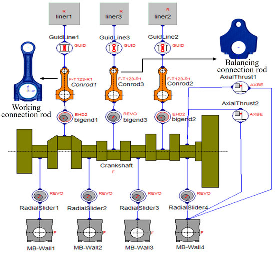
Figure 1.
Flexible Multi-Body Dynamics Model of Connecting Rod Group.
3. Bush Profile Design and Equation
A comparison between the traditional straight bush profile and an innovative arc-shaped bush profile is shown in Figure 2. Ignoring the bearing clearance for illustration purposes, the traditional bush profile along the axial direction shows two straight lines, while the arc-shaped bush profile has radial variation as a function of the axial distance. The geometric center on the bearing surface on the bearing surface is defined as zero. As the bearing profile’s axial position moves away from the middle point, the radial variation becomes greater and reaches the maximum at the edge.
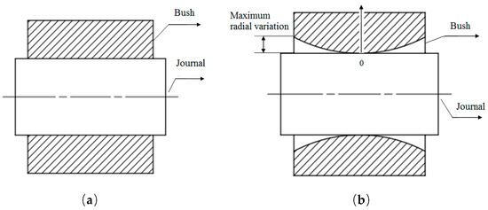
Figure 2.
Illustration of arc-shaped bush profile design. (a) Traditional straight bush profile; (b) Research bush profile.
At present, there are no widely recognized functional relationships between the bush profile and the bearing width, and there are no standard approaches to deduce the profile mathematically [15,16]. Therefore, four types of symmetric curves were used to model the bush profile in this study, namely the exponential, hyperelliptic, barrel, and trapezoidal profiles. The bearing profile definition is shown in Figure 3.

Figure 3.
Bush profile definition along the bearing axial direction.
The mathematical equations of the four types of bearing profiles are shown below.
The exponential profile’s equations
The hyperelliptic profile’s equations
The barrel profile’s equations
The trapezoidal profile’s equations
where Scam is the radial offset of the nominal diameter of the journal, Stop and Sbot are the radial variations at the left and right ends of the bearing profile, respectively, x is the bearing axial direction, Sr is the sum of Scam and the radial variation, x1 and x2 are the axial coordinates of the two ends of the bearing profile’s middle segment, and xm is the bearing width. T1 and T2 are the power exponents of the left and right segments of the bearing profile—each with a value of three—a and b are the lengths of the half major axis and half minor axis of the hyperelliptic profile, respectively, n is the power exponent of the hyperelliptic profile representing ovality, and n is six in this paper.
The radial variation refers to the y value shown in Figure 2, measured from the straight journal surface. Two maximum radial variation levels were used for each type of profile, 0.005 mm (5 μm) and 0.01 mm (10 μm), respectively. Therefore, eight different bearing profiles, as shown in Figure 4, were analyzed in a parametric simulation to study the effects of the maximum radial variation and profile types on lubrication performance before the DoE analysis was conducted.
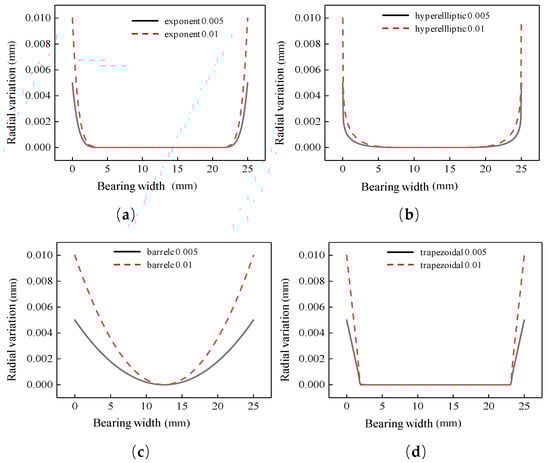
Figure 4.
Comparison between different bearing profiles with different maximum radial variations. (a) Exponential profiles; (b) hyperelliptic profiles; (c) barrel profiles; (d) trapezoidal profiles.
4. Influence of Bush Profiles on the Lubrication Performance of Connecting Rod Big-End Bearing
4.1. Exponential Bush Profiles
The influence of the maximum radial variation of the exponential profile on the MOFT of the connecting rod big-end bearing was studied by using the bearing dynamics simulation model. Figure 5 shows that the MOFT occurred at approximately 1090° crank angle. As the maximum radial variation increased from zero (baseline profile without any curvature) to 0.005 mm and then 0.01 mm, the MOFT first increased from 1.11 μm to 1.54 μm and then decreased to 1.25 μm. The 0.005 mm profile provided an increase of 0.43 μm in the MOFT relative to the baseline, and the 0.01 mm profile provided an increase of 0.14 μm. This simulation result indicates that an appropriate radial variation in the exponential profile can increase the MOFT. When the maximum radial variation exceeds a certain value, the MOFT may decrease to cause lubrication deterioration.
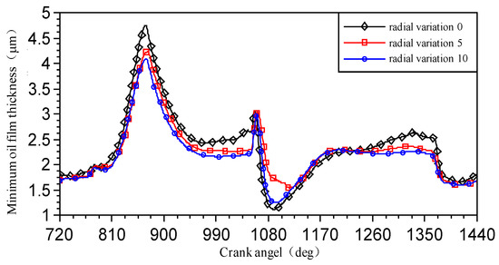
Figure 5.
Minimum oil film thickness given by exponential bush profiles.
Figure 6 shows the surface roughness contact pressures given by the exponential bush profiles. The maximum contact pressure also occurred at approximately 1090° crank angle. As the maximum radial variation increased from zero to 0.005 mm and then 0.01 mm, the maximum contact pressure first decreased from 71.57 MPa to 19.54 MPa and then increased to 48.92 MPa, corresponding to changes of 52.03 MPa and 22.65 MPa, respectively, relative to the baseline profile. The connecting rod journal has bending deformation under the impact of the in-cylinder firing pressure. An appropriate radial variation in the exponential profile can increase the load-carrying contact area, thus reducing the roughness contact pressure. However, as the maximum radial variation further increases, the load-carrying contact area becomes smaller, leading to an increase in the contact pressure.
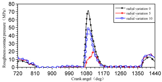
Figure 6.
Surface roughness contact pressure given by exponential bush profiles.
4.2. Hyperelliptic Bush Profiles
Figure 7 shows that the MOFT given by the hyperelliptic profiles also had minimum values at approximately 1090° crank angle. As the maximum radial variation increased from zero to 0.005 mm and then 0.01 mm, the MOFT first increased from 1.11 μm to 1.56 μm and then decreased to 1.26 μm. The 0.005 mm profile provided an increase of 0.45 μm in the MOFT relative to the baseline, and the 0.01 mm profile provided an increase of 0.15 μm.
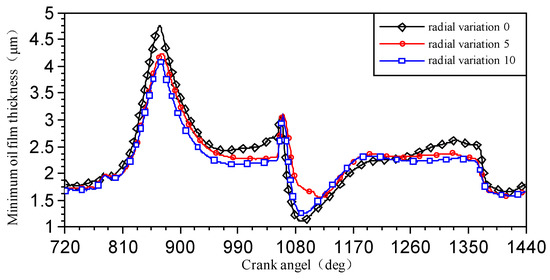
Figure 7.
Minimum oil film thickness given by hyperelliptic bush profiles.
The simulation result of the hyperelliptic bush profiles indicates the same mechanism affecting lubrication performance as shown by the exponential profiles. Both types of profiles have three segments in the profile design. The difference between these two types is that the middle segment of the exponential profile is a straight line with a changeable length, while the middle segment of the hyperelliptic profile is a curve with a slight curvature. Therefore, the latter is more advantageous in conforming to deformation by the middle part of the bush, hence providing better lubrication performance.
Figure 8 shows the surface roughness contact pressure given by the hyperelliptic bush profiles. The maximum contact pressure occurred at approximately 1090° crank angle. As the maximum radial variation increased from zero to 0.005 mm and then 0.01 mm, the maximum contact pressure first decreased from 71.57 MPa to 18.32 MPa and then increased to 47.06 MPa, corresponding to changes of 53.25 MPa and 24.51 MPa, respectively, relative to the baseline profile. Both the 0.005 mm and 0.01 mm profiles had lower contact pressures than the baseline profile, indicating better load-carrying capabilities and more uniform bearing load distributions.
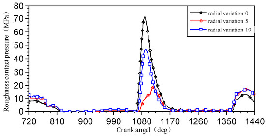
Figure 8.
Surface roughness contact pressure given by hyperelliptic bush profiles.
4.3. Barrel Bush Profiles
Figure 9 shows that the MOFT given by the barrel profiles had a minimum value at approximately 1090° crank angle. As the maximum radial variation increased from zero to 0.005 mm and then 0.01 mm, the MOFT first increased from 1.11 μm to 1.39 μm and then decreased to 1.07 μm. The 0.005 mm profile provided an increase of 0.28 μm in the MOFT relative to the baseline, and the 0.01 mm profile provided a decrease of 0.04 μm.
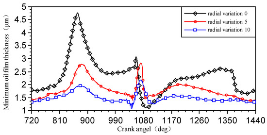
Figure 9.
Minimum oil film thickness given by barrel bush profiles.
At other crank angle locations, the MOFT given by the barrel profiles was all basically less than that given by the baseline profile. The overall reduced oil film thickness indicates worse lubrication performance of the connecting rod’s big-end bearing. The barrel profile has a greater transition gradient from the middle segment to the left or right end, and hence the effective load-carrying area is greatly reduced. Therefore, local metal-to-metal contact is prone to occur. It is more difficult to maintain effective hydrodynamic lubrication.
Figure 10 shows the surface roughness contact pressure given by the barrel profiles. The contact pressure had great variations within an engine cycle from 720° to 1440° crank angle and existed within the entire cycle. When the maximum radial variation of the barrel profile was 0.01 mm, the peak roughness contact pressure changed dramatically around the 1040° crank angle, reaching a maximum of 81.27 MPa. When the maximum radial variation increased from zero to 0.005 mm and then 0.01 mm, the roughness contact pressure first decreased from 71.57 MPa to 32.28 MPa and then increased to 81.27 MPa. Compared with the baseline profile, the 0.005 mm barrel profile reduced the roughness contact pressure by 39.29 MPa, and the 0.01 mm barrel profile increased the contact pressure by 9.7 MPa. The main reason is that the non-smooth transition in the barrel profile causes difficulties in maintaining an effective hydrodynamic lubrication oil film.
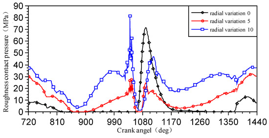
Figure 10.
Surface roughness contact pressure given by barrel bush profiles.
4.4. Trapezoidal Bush Profiles
Figure 11 shows that the MOFT had a minimum value at approximately 1090° crank angle. As the maximum radial variation increased from zero to 0.005 mm and then 0.01 mm, the MOFT first increased from 1.11 μm to 1.51 μm and then decreased to 1.23 μm. The 0.005 mm profile provided an increase of 0.40 μm in the MOFT relative to the baseline, and the 0.01 mm profile provided an increase of 0.12 μm. The trapezoidal profile consists of three segments, and its effect on lubrication is similar to the exponential profile. It can effectively conform to the deformation of the crank pin. When the maximum radial variation is appropriate, it can increase the oil film thickness. However, when the maximum radial variation exceeds a certain value, the oil film thickness may decrease, leading to worse lubrication.
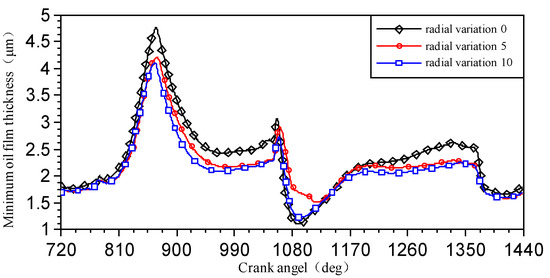
Figure 11.
Minimum oil film thickness given by trapezoidal bush profiles.
Figure 12 shows that when the maximum radial variation of the trapezoidal profile was 5 μm, the maximum roughness contact pressure occurred at a later timing of approximately 1115° crank angle. When the maximum radial variation increased from the baseline to 0.005 mm and then 0.01 mm, the roughness contact pressure first decreased from 71.57 MPa to 21.49 MPa and then increased to 51.29 MPa. Compared with the baseline profile, the contact pressure was reduced by 50.08 MPa by using the 0.005 mm profile and reduced by 20.28 MPa by using the 0.01 mm profile. The principle of reducing the contact pressure by using the trapezoidal profiles is similar to that of the exponential profiles. When the maximum radial variation is within a certain range, it can greatly reduce the contact pressure. When the maximum radial variation further increases, the probability of metal-to-metal contact becomes greater, leading to an increase in the contact pressure.
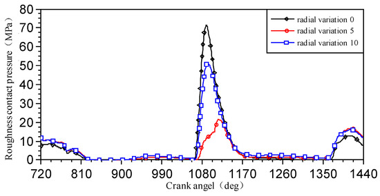
Figure 12.
Surface roughness contact pressure given by trapezoidal bush profiles.
According to the AVL software user manual, when the MOFT is greater than 1 μm, and the rough contact peak pressure is less than 50 MPa, the bearing is considered to be in normal working condition. The comparison of lubrication performance given by different profile types is shown in Table 3, which uses a maximum radial variation of 5 μm and the timing of a 1090° crank angle. When the connecting rod’s big-end bearing had a hyperelliptic profile, the MOFT reached 1.56 μm, and the roughness contact pressure was 18.32 MPa. Therefore, the hyperelliptic profile had the best comprehensive lubrication performance compared with the other three profile types and was hence selected for further analysis by DoE optimization.
Table 3.
Comparison of bearing lubrication performance of different bush profile types.
5. Parameter Optimization of the Connecting Rod Big-End Bearing Based on the RBF Neural Network Model
5.1. Factor Selection and Design of Experiments
The hyperelliptic profile was selected for further analysis due to its best lubrication performance among the four types of profiles. The DoE design factors included bearing clearance A, bearing width B, journal oil hole diameter C, and oil supply pressure D. The response parameters included the MOFT and the average peak asperity contact pressure (APASP). The APASP is the cycle average of the instantaneous surface roughness contact pressure within an engine cycle. The factor levels and ranges are shown in Table 4.
Table 4.
DoE factor levels.
The purpose of DoE is to use an effective partial factorial design to extract sufficient information from the runs with a minimum number of test runs and to find an optimal solution [17,18]. The Box–Behnken design was used to generate 25 runs in the DoE. Responses were simulated by using the AVL software Power Unit. The factor settings and the responses are shown in Table 5.
Table 5.
Normalized DoE factor levels and simulation results of responses.
5.2. Emulator Model Building and Evaluation
There are many artificial neural network algorithms that can be used to process DoE data. The radial basis function (RBF) neural network was selected as the fitting method to build an emulator model. The RBF neural network has a three-layer feed-forward structure [19], which is composed of an input layer, a hidden layer, and an output layer. The input layer receives the data of the four factors. The hidden layer handles nonlinear function mapping of the input data obtained from the input layer. The Gaussian function is usually used as an excitation function [20]. The output layer receives data from the hidden layer to perform linear weighting and summation. After a linear combination is completed, the output layer exports response parameters. The RBF emulator model of bearing lubrication is shown in Figure 13.
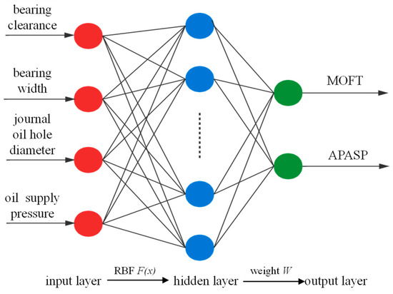
Figure 13.
RBF emulator model of bearing lubrication.
After the RBF neural network model is established, it is necessary to conduct model verification and accuracy analysis by cross-validation. Ten groups of data from the DoE factor space were randomly selected for accuracy analysis. The validation result is used to judge whether the emulator model can correctly reflect the relationship between the input factors and the response parameters. The evaluation criterion used in model validation is usually the coefficient of determination R2, as shown below:
where n represents the number of DoE runs, yi represents the response of the DoE run, represents the average of the response given by the RBF neural network model, and represents the fitted estimate of yi by using the emulator model.
The R2 of the MOFT was 0.991. The R2 of the APASP was 0.968. These R2 values indicate good accuracy of the RBF neural network model. Therefore, the model can be used for optimization.
5.3. Parameter Optimization of the Connecting Rod Big-End Bearing
The RBF neural network model was used to optimize bearing design parameters. The optimization constraint was the MOFT ≥ 1 μm. The MOFT and the APASP were selected as two objective functions to form a multi-objective optimization with tradeoffs. Since these two objectives have equal importance, their weighting ratio is 0.5:0.5. The optimization model of bearing lubrication is expressed as follows:
where A, B, C, and D represent the four factors, i.e., bearing clearance, bearing width, journal oil hole diameter, and oil supply pressure, respectively; f1(x) and f2(x) represent the MOFT and the APASP, respectively.
In the Isight analysis software, the NSGA II was used to handle the multi-objective optimization. The initial population size was set to 20. The largest number of iterations in evolution was set to 50. The crossover probability constant was set to 0.9. A total of 1000 data points were used in optimization. The final results of the optimized factor settings and the corresponding responses are shown in Table 6. It is observed that the optimized design was different from the initial design. The design values of the bearing clearance A were basically unchanged. The design values of the bearing width B, the journal oil hole diameter C, and the oil supply pressure D all increased, leading to a greater load-carrying area in the bearing and hence reduced lubricant oil film pressure. However, an excessively large bearing width may increase the friction loss of the oil along the flow path, which is also not conducive to oil heat dissipation. An increased oil supply pressure can increase the oil flow in the bearing and help maintain an effective hydrodynamic lubrication oil film.
Table 6.
Multi-objective optimization results of the connecting rod big-end bearing.
Figure 14 shows that the optimized design improved comprehensive lubrication performance by raising the MOFT from 1.56 μm to 1.97 μm, with an increase of 0.41 μm, and reducing the APASP from 3.97 MPa to 0.25 MPa, with a decrease of 3.72 MPa.
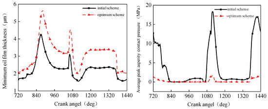
Figure 14.
Comparison of lubrication performance before and after optimization.
6. Conclusions
Four types of bush profiles were designed, namely exponential, hyperelliptic, barrel, and trapezoidal profiles for the connecting rod big-end bearing, and the effects of hyperelliptic bearings on connecting rod big-end lubrication and design optimization were researched. Based on the results, the following conclusions can be drawn:
- (1)
- When the maximum radial variation increased from the baseline profile, the MOFT first increased and then decreased, and the surface roughness contact pressure first decreased and then increased. The exponential, hyperelliptic, and trapezoidal profiles improved the comprehensive lubrication performance of the connecting rod. Denoting the maximum radial variation as 0.005 mm and 0.010 mm, the 0.005 mm profiles performed better than the 0.010 mm profiles;
- (2)
- By using the best profile type, the hyperelliptic profile, a DoE simulation was conducted with four factors, i.e., bearing clearance, bearing width, journal oil hole diameter, and oil supply pressure. The RBF neural network model was developed to fit the DoE data. The MOFT and the APASP were used as two objective functions in optimization. The NSGA-II method was used to complete multi-objective optimization. The optimized MOFT increased from 1.56 μm to 1.97 μm, and the optimized APASP decreased from 3.97 MPa to 0.25 MPa.
Author Contributions
Conceptualization, D.J.; methodology, D.J.; software, C.L.; validation, H.J.; formal analysis, W.D.; investigation, L.H.; resources, D.J.; data curation, D.J.; writing—original draft preparation, C.L.; writing—review and editing, D.J. and W.D.; visualization, C.L.; supervision, D.J.; project administration, W.D.; funding acquisition, D.J. All authors have read and agreed to the published version of the manuscript.
Funding
This research was funded by Major Science and Technology Planning Projects of Yunnan Province Science and Technology Department, grant number 202202AC080006.
Data Availability Statement
Not applicable.
Conflicts of Interest
The authors declare no conflict of interest.
References
- Zhao, Z.; Wang, G.; Wang, Y.; Zhang, L.; Xu, C.; Wu, Y.; Li, X. Comparison of lubrication and structure for connecting rod small end bearing for an 8v diesel engine. Veh. Engine 2017, 2, 78–82. [Google Scholar]
- Zhang, Z.; Liu, J.; Song, X.; Zhang, L.; Zhao, Z.; Liu, Y.; Liang, Y. Lubrication characteristics analysis of connecting rod small end bearing and piston pin for diesel engine. Veh. Engine 2018, 3, 59–66. [Google Scholar]
- Moiseev, Y. Analysis and validation of the dynamic method for diagnosing diesel engine connecting rod bearings. Transp. Probl. 2018, 13, 123–133. [Google Scholar]
- Huang, F.; Peng, J.; Bi, Y.; Li, N.; Lei, J. A study of bearing thermal elastohydrodynamic lubrication characteristics for non-road diesel engine. Lubr. Eng. 2019, 44, 57–64+70. [Google Scholar]
- Qin, Z.; Xiang, J.; Zhong, C.; Li, C. The influence of connecting rod small end bushing profile on its friction pair lubrication and deformation characteristics. Chin. Intern. Combust. Engine Eng. 2020, 41, 70–79. [Google Scholar]
- He, Z.; Sun, Y.; Zhang, G.; Hong, Z.; Xie, W.; Lu, X.; Zhang, J. Tribilogical performances of connecting rod and by using orthogonal experiment, regression method and response surface methodology. Appl. Soft Comput. J. 2015, 29, 436–449. [Google Scholar] [CrossRef]
- Lavie, T.; Fransisco, A.; Fatu, A.; Villechaise, B. Multiobjective optimization of conrod big-end bearing lubrication using an evolutionary algorithm. Tribol. Trans. 2015, 58, 490–499. [Google Scholar] [CrossRef]
- Bi, F.; Liu, B.; Liu, C.; Tian, C.; Li, X.; Ma, T. Research on the lubrication of diesel engine connecting rod small end bearing based on thermoelastic model. Intern. Combust. Engine Eng. 2018, 39, 15–22. [Google Scholar]
- Wu, Q.; Zhou, R.; Chen, T.; Dong, C.; Zhang, G. Lubrication analysis of connecting rod bearings of two stroke marine diesel engine based on multi-body dynamics. Lubr. Eng. 2019, 44, 103–108. [Google Scholar]
- Ruan, D.; Chen, L.; Gao, Z. Effects of shell profile modification of engine conrod bearings on lubrication characteristics. China Mech. Eng. 2019, 30, 1207–1211+1218. [Google Scholar]
- Zhang, J. Study on Lubrication Performance of U-Shaped Connecting Rod Large Head Bearing. Master’s Thesis, Shandong University, Ji’nan, China, 2016. [Google Scholar]
- Bernhauser, L.; Heinisch, M.; Schörgenhumer, M.; Nader, M. The Effect of Non-Circular Bearing Shapes in Hydrodynamic Journal Bearings on the Vibration Behavior of Turbocharger Structures. Lubricants 2017, 5, 6. [Google Scholar] [CrossRef]
- Offner, G.; Knaus, O. A Generic Friction Model for Radial Slider Bearing Simulation Considering Elastic and Plastic Deformation. Lubricants 2015, 3, 522. [Google Scholar] [CrossRef]
- Razavykia, A.; Delprete, C.; Baldissera, P. Numerical Study of Power Loss and Lubrication of Connecting Rod Big-End. Lubricants 2019, 7, 47. [Google Scholar] [CrossRef]
- Zhang, C. Study on the Effect of Connecting Rod Recirculation on the Elastic Hydrodynamic Lubrication Characteristics of Connecting Rod Bearings. Master’s Thesis, Kunming University of Science and Technology, Kunming, China, 2016. [Google Scholar]
- Zhang, L.; Wang, G.; Wang, Y.; Zhao, Z.; Zhang, Z.; Song, X. Wear analysis and surface profile design of a diesel engine piston pin bearing. Acta Armamentarii 2018, 39, 1892–1900. [Google Scholar]
- Chen, K. Experimental Design and Analysis; Tsinghua University Press: Beijing, China, 2005. [Google Scholar]
- Lai, Y. Isight Parameter Optimization Theory and Examples in Detail; Beijing University of Aeronautics and Astronautics Press: Beijing, China, 2012. [Google Scholar]
- Yuan, K.; Liu, Y.; Sun, J.; Luo, X. Research on control of underwater manipulator based on fuzzy RBF neural network. Chin. J. Eng. Des. 2019, 26, 675–682. [Google Scholar]
- Wang, D.; Wang, L.; Chen, Z.; Wu, X.; Zhang, S. Application of robustness and light weight in optimal design of door structure. Mech. Sci. Technol. Aerosp. Eng. 2019, 38, 626–633. [Google Scholar]


Disclaimer/Publisher’s Note: The statements, opinions and data contained in all publications are solely those of the individual author(s) and contributor(s) and not of MDPI and/or the editor(s). MDPI and/or the editor(s) disclaim responsibility for any injury to people or property resulting from any ideas, methods, instructions or products referred to in the content. |
© 2023 by the authors. Licensee MDPI, Basel, Switzerland. This article is an open access article distributed under the terms and conditions of the Creative Commons Attribution (CC BY) license (https://creativecommons.org/licenses/by/4.0/).