Article

Lubricant-Free Thermoforming Mold Using Pulse Electrochemical Polishing

Department of Mechanical Engineering, Chosun University, 10, Chosundae 1-gil, Dong-gu, Gwangju 61452, Republic of Korea
*
Author to whom correspondence should be addressed.
Lubricants 2023, 11(9), 373; https://doi.org/10.3390/lubricants11090373
Submission received: 30 June 2023 / Revised: 29 August 2023 / Accepted: 30 August 2023 / Published: 4 September 2023
(This article belongs to the Special Issue Tribology in Processing and Application of Steels)

Abstract

:
Thermoforming (TF) is a process used for fabricating products by applying heat and vacuum pressure to a plastic film or plate. Typically, TF molds require post-processing, resulting in additional costs and time consumption. Furthermore, continuous application of lubricant is necessary to prevent corrosion and facilitate mold release. Electrochemical polishing (ECP) is a technique used to achieve a polished surface on metal through an electrochemical reaction. In this research, a novel approach is proposed as a solution to the need for lubricants and manual post-processing in mold preparation, utilizing pulse electrochemical polishing (PECP). A comparative analysis is conducted on the reproducibility of products and the forces required for mold release among molds prepared using PECP, lubricated molds, and unpolished molds. To assess product reproducibility, the radii of curvature of all mold steps and grooves are determined and compared. Furthermore, peeling tests are conducted to estimate the forces required for mold release. Product surface evaluation is performed using atomic force microscopy, while lateral force microscopy is employed to measure the reductions in surface frictional force achieved by PECP.

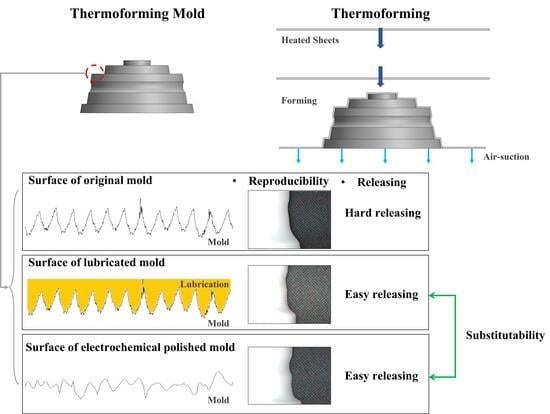
Graphical Abstract

1. Introduction

1.1. Thermoforming

Thermoforming (TF) is a versatile manufacturing method that employs heat and pressure to deform flat or film-like plastic materials into predefined shapes by aligning them with simple mold structures devoid of undercuts [1]. This technique is advantageous for the rapid forming of plastic sheets and is particularly effective in prototyping applications. The thermoforming process begins by heating a flat plastic sheet to a specific forming temperature, thus rendering it malleable. Following this, the plastic sheet is pressed tightly against a mold. The application of consistent air pressure and force allows the malleable plastic to adapt to the intricate contours of the mold. The inclusion of a vacuum in the interstitial space between the plastic sheet and the mold further enhances this molding process, thereby enabling the final product to precisely mirror the shape of the mold [2]. Therefore, TF has been extensively adopted across various sectors, including prototype manufacturing and education [3]. With the progressive miniaturization and personalization of products in contemporary industries, TF has emerged as an appropriate process to meet these demands. Nevertheless, the application of simple metal molds in TF poses certain challenges. Molds created using machining processes necessitate supplementary post-processing procedures, given that the machining tools make direct contact with the material, leaving discernable feed marks on the surface. The surface roughness of thermoforming molds depends on the characteristics of the product. For non-appearance products, roughness is typically set in the 200 to 300 µm range and is achieved most commonly by sandblasting. In contrast, for appearance products, mold tolerance, surface roughness, and texture are influenced by the intended application of the product and the tactile requirements of the end user. As a result, mold surface standards vary from industry to industry. The thermoforming process can replicate textures approaching 50 µm in roughness, meaning that the texture of the mold can significantly affect the surface finish of the final product [4]. These finishing tasks are often manual and consume substantial time and resources, undermining the objectives of expedited production and shaping. The situation becomes more challenging when the molds have curved surfaces, as accessing them with tools becomes difficult. After manufacturing, molds require regular lubrication to safeguard against corrosion and aid in the releasing process. During the forming process, the use of lubricants is inevitably expended due to the essential requirement for mold release, thus leading to continuous consumption as the process ensues. With growing environmental consciousness and stricter global environmental regulations, continuous lubricant consumption has become less desirable. Moreover, the residual lubricant on the product surface may pose potential health risks to users, necessitating the degreasing of the thermoformed products before their introduction into the marketplace [5]. Nonetheless, eliminating residual lubricants from the micro-scale valleys or depressions on the surface poses several technical challenges.

1.2. Electrochemical Polishing

Electrochemical polishing (ECP) is a non-traditional surface polishing technique that employs electrochemical reactions to accomplish surface refinement [6,7]. ECP shares its material removal mechanism with electrochemical machining (ECM) [8]. The configuration of the ECM process resembles that of an electroplating procedure but with reversed electrical polarity, leading to the dissolution of the material at the anode through electrochemical reactions, thereby enabling the material to be machined. ECM, which capitalizes on these electrochemical reactions, is predominantly utilized in various sectors for the machining of difficult-to-cut materials and deburring applications [9]. ECP is a process that minimizes surface machining in the fundamental mechanism of ECM and utilizes the effect of the film generated by relatively slow electrochemical reactions, resulting in various surface functionalities. Unlike traditional machining processes, ECP possesses a multitude of distinctive features. Conventionally machined metal surfaces often retain contaminants while maintaining altered layers that act as corrosion-initiation sites and facilitate corrosion propagation. Such corrosion advances persistently without the formation of passivation layers. Figure 1 illustrates the general procedure of ECP. Prior to the ECP process, tools and workpieces are secured at a predetermined distance, with the intervening space filled with an electrolyte. The workpiece and the electrode are connected to the anode and cathode, respectively. The electrochemical reaction commences upon the application of power. Once the current is applied, metal atoms at the anode surface oxidize and migrate into the solution. The current density intensifies at micro-scale peaks, causing faster dissolution compared to valleys, resulting in a smoother surface; hydrogen gas forms at the cathode, and oxygen gas forms at the anode along with metal dissolution. The electrochemical reaction operates under a diffusion mechanism. The diffusion mechanism mentioned leads to the formation of a viscous film on the anode. The increasing resistance of this film prevents the efficiency of the electrochemical reaction from increasing and aids in controlling the uniformity of metal dissolution. In Figure 2, the progression of polishing can be observed originating from the C-D region, often referred to as the plateau, in the depicted curve. As ECP progresses, impurities on the workpiece surface are eliminated, leading to the leveling and brightening of the anodic surface within this viscous film. Subsequently, a passive film forms. Over time, micro-scale valleys become smoother, resulting in a more uniform surface. This passive film enhances the corrosion resistance of the workpiece. Nonetheless, despite the broad surface appearing smoother, it does not become entirely flat, which is an inherent characteristic of ECP. The aforementioned electrochemical reaction also facilitates material removal in stainless steel. For stainless steel, elements like chromium on the surface react with the oxygen gas produced on the anode during electropolishing. This reaction results in the formation of a characteristic layer of chromium passivation film [10,11]. Another remarkable characteristic of ECP is its non-contact processing, wherein the workpiece and tool remain free from direct interaction. This approach effectively reduces residual stress on the surface, and the tools utilized in this process have an indefinite lifespan, ensuring long-term durability and sustained performance [12].

1.3. Literature Review

ECP, developed in the 1930s, saw significant contributions from Jacquet in establishing its foundations and investigating material removal and has been the subject of continuous research ever since [13]. Notably, “The double-layer theory” was supplemented by Hoar and Grimm to establish the operational mechanism of ECP [14,15]. Efforts have been directed towards enhancing the efficiency of ECP by investigating process variables. For instance, Park et al. developed pulse electrochemical polishing (PECP), a technique that modulates the rate of electrochemical reactions by utilizing pulsed signals for electrical power [16]. The anodic pulse modulates the current distribution by adjusting both the pulse duration and peak voltage, optimizing mass transport. Incorporating an off-time aids in the replenishment of reactive species and the expulsion of byproducts and heat. Notably, pulsed currents offer enhanced control over precise pattern transfer, presenting a distinct advantage over other variables, such as electrolyte composition, operational temperature, anode material, and meticulous mechanical experimental configurations [17]. This approach aids in maintaining surface shape during machining and reduces excessive electrochemical reactions. Kim et al. examined the relationship between bubble formation and electrochemical reaction by incorporating ultrasound into ECP [18]. Rech et al. researched the concept of hybrid machining, integrating electrochemical and physical techniques, to overcome the constraints of purely physical machining [19]. ECP has been adopted in a diverse range of industries that necessitate ultra-clean surfaces with high corrosion resistance, such as semiconductor equipment parts (valves, fittings, etc.), chemical industry pipes, and food manufacturing equipment. The biocompatible surface characteristics of ECP make it suitable for biomedical implants and dental applications [20,21,22]. Recently, ECP has been explored as a post-processing technique for additive manufactured products [23,24]. Despite its merits, the use of electrolytes in ECP, which comprise strong acids, is not exempt from recent environmental regulations. Therefore, research is being conducted to develop eco-friendly ECP processes. One such initiative involves the use of ionizing solutions as a substitute for strong acids in ECP, as investigated by Abbott et al. [25]. Additionally, to reduce the consumption of cleaning solutions and improve worker safety, a solid-state electrolyte-based process called DECP has been developed, sparking various associated studies [26,27]. In the field of lubricant research, environmental issues have led to a significant research effort focused on devising environmentally friendly methods to minimize the amount of lubricant used. Minimal quantity lubrication (MQL) technology has emerged as a promising avenue to mitigate the economic and environmental burden attributable to excessive lubricant usage [28,29]. Simultaneously, researchers are exploring potential environmentally friendly materials that could serve as viable alternatives to conventional petroleum-based lubricants. The distinct features of ECP, namely its non-contact machining process and elevated corrosion resistance, could potentially address the challenges of time and cost associated with the finishing of TF molds, as discussed previously. Moreover, it could offer an alternative to the lubricants used for corrosion prevention in molds. More recently, the footprint of manufacturing processes has been studied. P. Stavrpoulos et al. studied a comparison between traditional and non-traditional machining and concluded that replacing the finishing and lubrication of molds with a single ECP process would have an economic contribution by reducing processes in addition to the environmental benefits [30]. Due to its various characteristics, ECP is sometimes applied to the surface of the mold [31]. Furthermore, the variability in surface quality that arises due to manual finishing, a persistent issue in traditional finishing methods, could be effectively minimized using ECP. However, whether ECP can comprehensively replace lubricants, especially its effect on release properties, requires further investigation. In thermoforming applications, the impact of frictional forces is inextricably tied to the fabrication or release of a product. The material flow throughout the molding process is largely dictated by the frictional force exerted on the surface of the mold, which, in turn, determines the reproducibility of the final product. In conventional thermoforming processes, lubricants are typically employed to streamline the molding and releasing of products. The tribological properties are intrinsically connected to the surface profile. ECP has been recognized for its ability to refine surfaces, subsequently reducing surface roughness and diminishing friction [32]. Therefore, in terms of lubrication research, it is necessary to determine the feasibility of replacing lubricants used in TF applications with ECP.
In this study, we used three different types of molds to assess the potential application of ECP in TF molds. These consisted of a machined mold, a lubricant-sprayed mold, and an ECP mold. The mold characteristics were thoroughly analyzed via peeling tests and lateral force microscopy (LFM) facilitated by atomic force microscopy (AFM) [33]. Simultaneously, we conducted a comparative evaluation of the shape reproducibility during the TF process for each mold type and examined the impact of the mold on the thermoformed products through a detailed micro-surface analysis. Through the analysis of the surface profile and surface roughness of each mold and the surface roughness of the molded product, the correlation between the surface roughness and the molding quality of the product corresponding to each mold was determined. Based on these insights, we propose an environmentally friendly lubricant-free TF mold with ECP as an alternative to conventional lubricants used in molds.

2. Experimental Setup

The current study comprises an investigation of four stages to evaluate the effects and confirm the characteristics when implementing ECP on molds used in TF processes. In the first stage, ECP was applied to an unpolished mold (ECP mold) with different steps and grooves to create experimental groups. Control samples for comparison included an unpolished mold (original mold) and a mold that was sprayed with lubricants (lubricated mold). In the second stage, molds subjected to each condition were utilized in the TF process, and the reproducibility fidelity of the thermoformed products was compared. The third stage involved measuring the force required for mold and product release. Lastly, in the fourth stage, the product surface was analyzed using AFM, emphasizing the friction characteristics of the ECP surface as probed by LFM.

2.1. PECP Process for the TF Mold

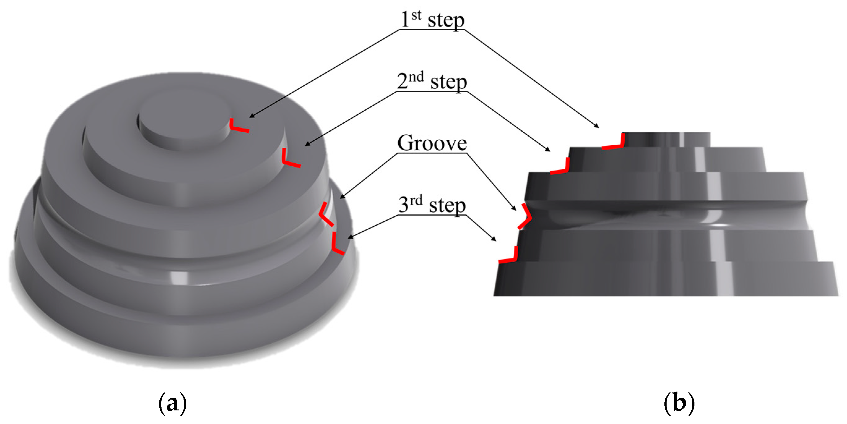
The molds deployed in this study were fabricated through turning processes. The molds exhibited a diameter of 70 mm and a height of 33 mm. Figure 3a,b depict the isometric and side views of the molds, respectively. The molds were constructed from STS304 material and featured three distinct steps along with a single groove.
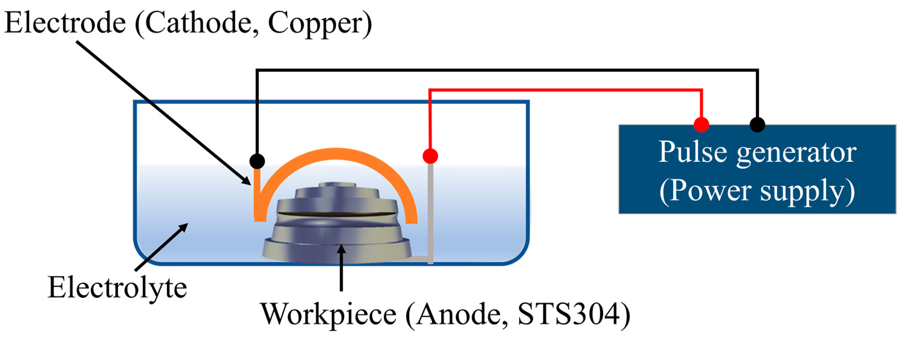
The composition of the acidic electrolyte used in the PECP is detailed in Table 1. The composition of the electrolyte is presented in terms of molarity. The pH value of the electrolyte is approximately zero, denoting a strongly acidic solution. PECP was chosen over the direct current approach to maintain the integrity of the mold shape by changing the type of electrical power used. Table 1 provides a detailed description of the specific electrical conditions implemented during PECP. The PECP process was executed based on optimized conditions derived from relevant references [34]. As depicted in Figure 4, the copper electrode was fabricated to match the shape of the mold, ensuring consistent spacing. While there exists a tolerance of approximately 2 mm in certain sections of the gap, it does not significantly influence the outcomes that are the primary focus of this study, specifically those concerning the presence or absence of PECP [35]. In the PECP process, a semi-permanent electrode surface that had not undergone oxidation was utilized, and it did not influence the polishing results [36]. The PECP process time was limited to 720 s, which is shorter than traditional post-processing times. After PECP, the molds were subjected to cleaning and drying operations to preserve their conditions, ensuring consistency among the molds.

2.2. TF and Analysis of Shape Reproducibility

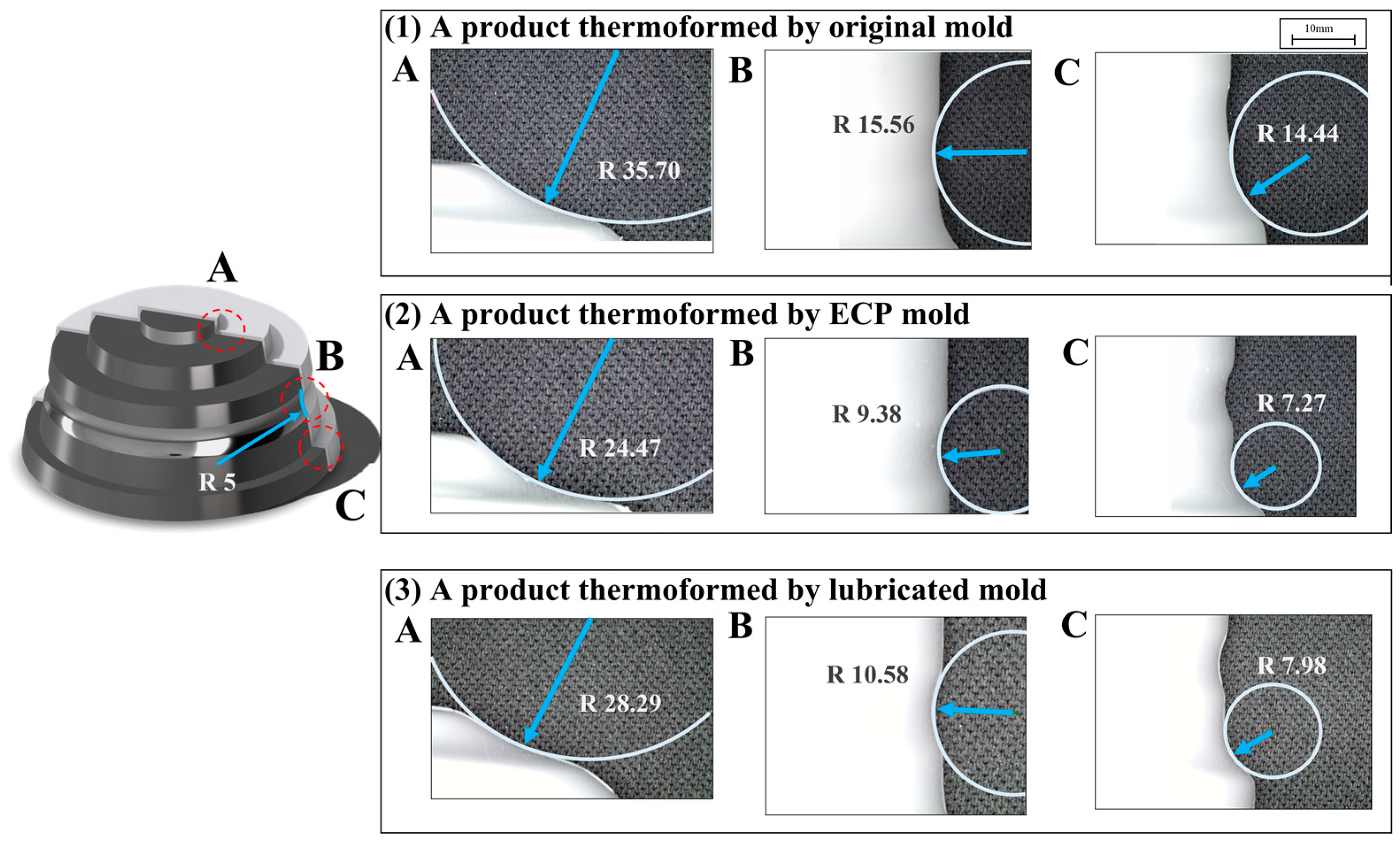
TF experiments were conducted employing three different types of molds: original mold, lubricated mold, and the ECP mold. A standard mold release agent, comprising a combination of silicone and urethane, was utilized for mold lubrication. The lubricant was sprayed onto the mold in a circular pattern at regular intervals during the TF process. The TF process was carried out using a DT2 (Vaquform) system, as illustrated in Figure 5. Each mold was placed at the base of the TF machine, and an acrylonitrile butadiene styrene (ABS) sheet was placed on top. When heat is applied to the sheet, raising its temperature to 210 °C, the sheet is lowered to the bottom and pressed against the mold while air is sucked in from the bottom of the machine to continue the forming process. The products formed from each type of mold were examined under a microscope to evaluate shape reproducibility, with specific attention given to the locations of the first and third steps and the groove. The curvature radii were measured to enable comparison.

2.3. Peeling Test

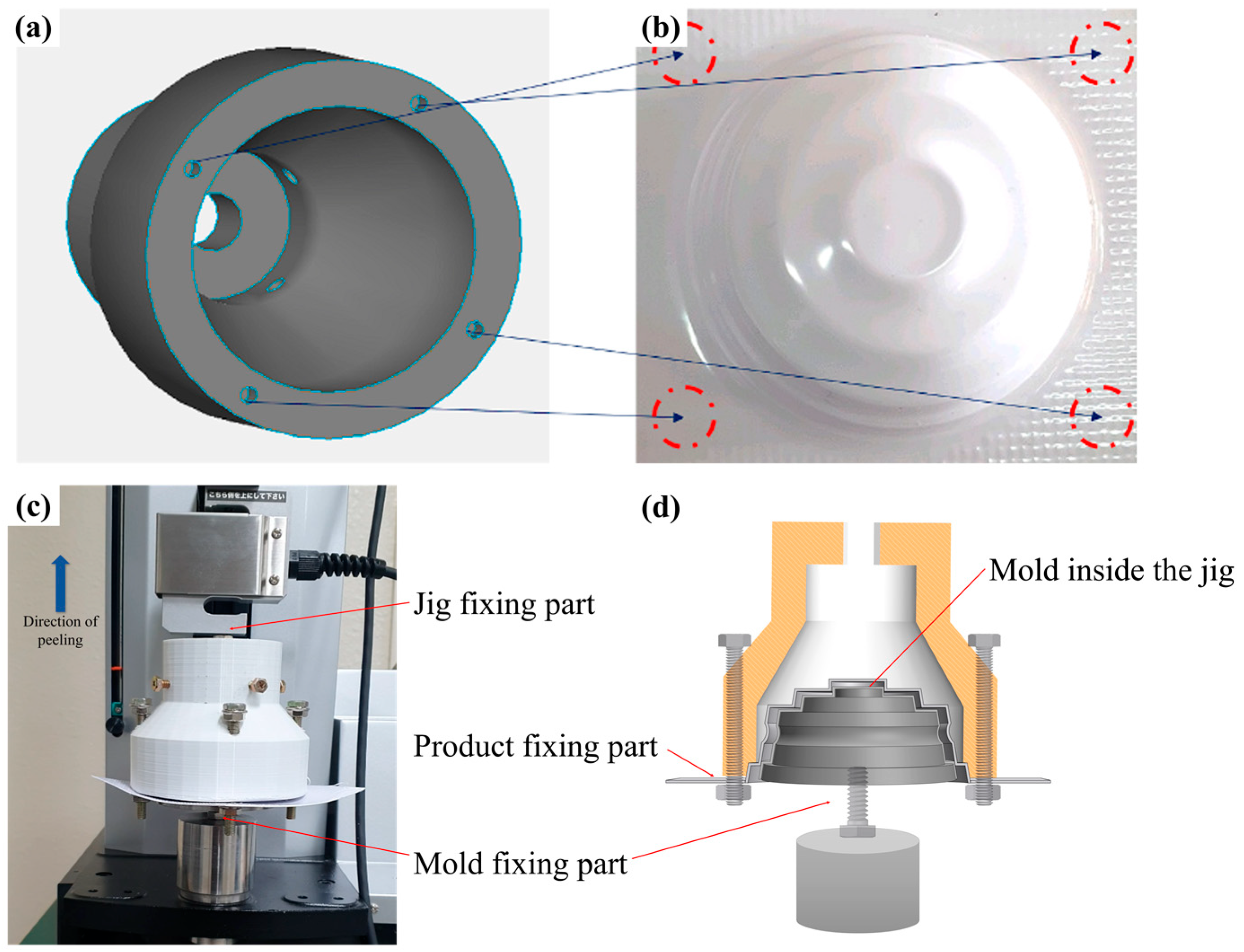
A peeling test apparatus was employed to gauge the force required for mold release. Figure 6a showcases the jig used for the peeling test, while Figure 6b shows the top view of the thermoformed product. For the peeling test, the bottom section of the mold was bolted to the lower part of the peeling test machine for stability. The upper part of the peeling test machine made contact with the ABS sheet, which adhered to the mold, thus necessitating a jig that conforms to the shape. The jig was fixed using bolts with holes drilled in each of the same locations as the four holes in the ABS sheet (Figure 6a,b). After the TF process with each type of mold, the product and mold were affixed to the peeling test apparatus, while the ABS sheet maintained contact with the mold. Figure 6c depicts the configuration of the peeling test setup. The mold is not visible because it is inside the jig but is shown schematically in Figure 6d for clarity. The peeling test apparatus pulled the jig upward, and the force measured during this process was compared to analyze the release characteristics of the different mold conditions.

2.4. Measurement of Product Surface Morphology Using AFM and Tribological Characterization Using LFM Mode

The micro-scale surfaces of products formed with each mold type were measured using AFM (Park systems XE100 Korea, Suwon, Republic of Korea), facilitating a comparative analysis of the surfaces. This approach enabled us to examine the surface of the ABS sheet prior to TF and assess the impact of the mold surface on the ABS sheet. Initially, we measured the mold surface and compared it with the surface of the thermoformed product. The mold surface measurement was performed using a surface profiler (Mitutoyo SV2100M4, Kawasaki, Japan). The total measurement length was 1.5 mm. The micro-scale morphology of the ABS sheet surface was measured before TF. Subsequently, the surfaces of the products formed with the ECP mold and the original mold were measured using the surface of the ABS sheet as a reference. The analysis aimed to determine how the ABS surface changes with each type of mold surface quality. The measurement range was 30 × 30 μm2. We compared the cross-sectional profiles of the central region of each measured surface and performed a comparative analysis of the profiles based on Ra and Rz values. Furthermore, we also evaluated the friction of metal surfaces with and without PECP. This involved comparing and analyzing the lateral forces observed on flat surfaces comprised of the same material as the mold. This analysis was performed using the LFM mode of an AFM. LFM is acknowledged as a comprehensive technique for the evaluation of microscale surface tribological properties. The probe used in the LFM mode was the NSC36 (Silicon, Al BS.) contact-mode cantilever manufactured by Mikromasch. It is predominantly employed in LFM mode. In the context of our study, an apt methodology was determined to elucidate the surface tribology associated with an ECP process, known for its effectiveness in enhancing surface smoothness at a corresponding microscale. For this study, we selected a PECP plate with a surface area of 1 cm2 and an unpolished specimen for measurement, given their suitability for AFM measurement. The PECP process was repeated under specific electrical conditions described in Table 1. The PECP process was performed under optimized polishing conditions, as stated in reference [34]. The measurements were conducted with a scanning size of 30 × 10 μm2 and a scanning speed of 0.1 Hz. A constant tensile force of 8.5 nN was sustained throughout the measurement. Both topographical and lateral force data were recorded to facilitate a comparative analysis of the surface friction characteristics among different specimens. After measuring both forward and backward signals, we adjusted the waveform to obtain the LFM signal using the offset values derived from the flat region of the friction loop [37].

3. Results

3.1. Comparative Analysis of the Reproducibility of Thermoformed Products in Different Types of Molds

Figure 7 illustrates the radius of curvature at each step and groove for the thermoformed products created with each mold type. Figure 7A represents the first step, Figure 7B indicates the groove between the second and third steps, and Figure 7C illustrates the third step. Figure 7(1) shows the radius of curvature at each position of the part thermoformed from the original mold. Figure 7(2,3) show the radius of curvature at each location for products molded with an ECP mold and a lubricated mold. The radius of curvature for each step and groove of the products formed with the mold in Figure 7(1) was larger than that of the corresponding locations in Figure 7(2,3). Specifically, the radius of curvature for the groove section was 5 mm for the original mold, 9.38 mm for the product formed with the ECP mold, and 10.58 mm for the product formed with the lubricated mold. These values were closer to the original radius of curvature than the 15.56 mm value for the product formed with the original mold. Figure 7 represents the general trend of shape reproducibility, and the values have a margin of error in each case. To investigate the average values, Figure 8 presents the average, maximum, and minimum radius of curvature at various locations of the thermoformed products created with each mold type. Each data point represents the average radius of curvature of five products thermoformed in the same location. The radius of curvature at position A for the products formed with the original mold was 32.97 mm, and for the lubricated mold was 32.78 mm, both of which were larger. In contrast, it was 23.89 mm for the products formed using the ECP mold, which was smaller. However, for the groove and the third step, the products thermoformed with the lubricated mold had the lowest values, 10.37 mm and 9.47 mm, respectively, compared to the average values of the other products. In summary, the products thermoformed with the lubricated mold demonstrated lower radii of curvature compared to those formed with the original mold, while the products thermoformed with the ECP mold exhibited similar radii of curvature. As the radius of curvature signifies reproducibility, the ECP mold and the lubricated mold showed superior performance compared to the original mold. The lubricated mold exhibited higher values compared to the products formed with the ECP mold at location A, while in locations B and C, the values were similar or slightly lower than those of the products formed with the ECP mold. This difference seems to be attributable to variations in the degree of lubricant application depending on the location. However, it is clear that products formed with the ECP mold demonstrated higher shape reproducibility compared to those created with the original mold.

3.2. Analyzing the Impact of Mold Surface Quality on the Surface of Thermoformed Products

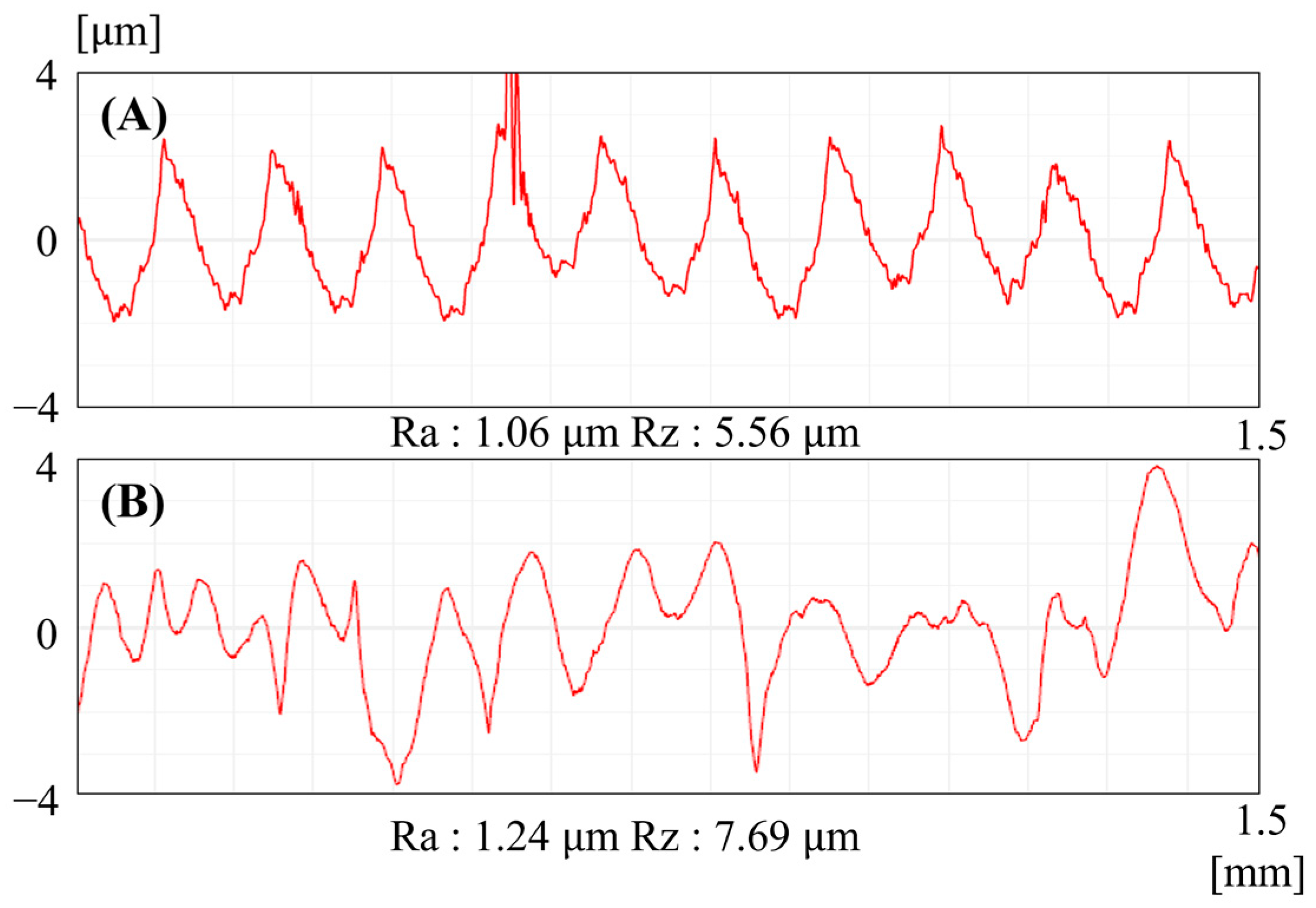
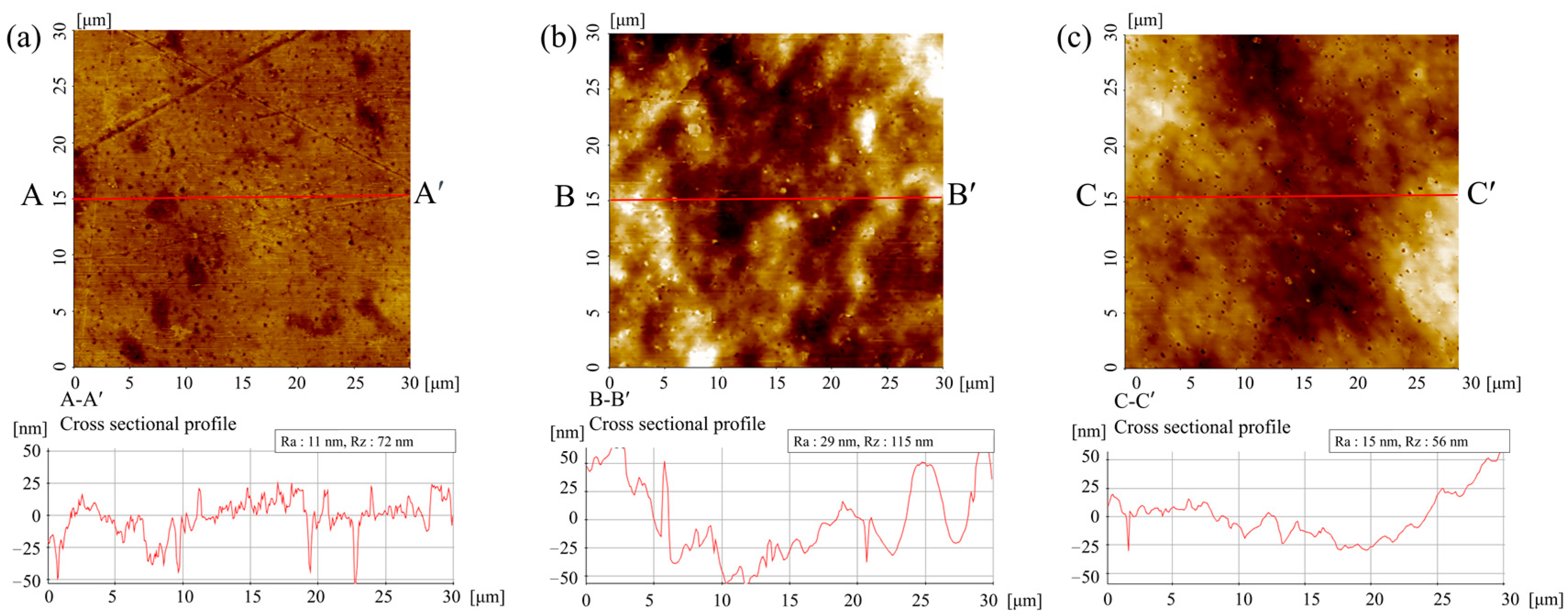
Figure 9 presents the measured results of the mold’s surface according to the application of ECP. The original mold denotes the profile of the mold prior to polishing (Figure 9A). The feed marks generated by the machining process are clearly visible, along with micro-scale peaks. Following the application of PECP, the mold exhibits a modified profile, as depicted in Figure 9B. Electrochemical reactions have melted and smoothed the profile peaks, whereas the valleys are in the process of being leveled due to the formation of passivation layers. Since PECP does not effectively reduce waviness, broad-range leveling was not observed, but a more localized smoothing effect is visible. AFM morphology images in Figure 10 show the impact of mold surface quality on the ABS sheet surface. Figure 10a depicts the surface of the ABS plate before TF. While some defects are present, the overall surface appears flat. The Ra and Rz values for the A-A′ cross-sectional profile are 11 nm and 72 nm, respectively. Figure 10b illustrates the surface of the product thermoformed with the original mold, which has the roughest surface profile with an Ra of 29 nm and an Rz of 115 nm for the B-B′ cross-sectional profile. Figure 10c illustrates the surface of the product thermoformed with the ECP mold. The Ra value is 15 nm, not significantly different from the surface of the original ABS sheet. However, the Rz value has decreased slightly to 56 nm. The C-C′ cross-sectional profile is smoother than the pre-formed profile demonstrated in Figure 10a. These findings suggest that the fine surface smoothing of the mold via PECP has a notable effect on the surface of the thermoformed product.

3.3. Peeling Test Results

Figure 11 illustrates the measured release force over time for the three different mold conditions. The recorded maximum forces were 129.5 N for the lubricated mold, 142.8 N for the ECP mold, and 205.1 N for the original mold. The maximum force differential was approximately 10 N between the lubricated mold and the ECP mold. Between the lubricated mold and the original mold, there was a difference of approximately 70 N and a difference of roughly 60 N between the ECP mold and the original mold. These results offer clear evidence of the positive impact of PECP on the release process of the formed products.

3.4. Analysis of Friction Properties Using LFM

Figure 12 presents the topography and LFM measurements performed on the original STS304 surface and the PECP surface (STS304). This was done using AFM to investigate the friction properties. The topography, LFM, and cross-sectional view are shown in Figure 12 in this order. In LFM mode, the intensity of the measured voltage was used to determine the friction characteristics of the relative surfaces. Figure 12a depicts the topography of the original STS304 surface, whereas Figure 12d shows the topography of the surface post-PECP. Notably, Figure 12a exhibits the original surface with its characteristic deep valleys, while Figure 12d reveals a considerably smoother surface after PECP but with some particle boundaries remaining. In Figure 12b, the LFM visualization distinctly highlights augmented transverse forces alongside isolated regions rendered in a pronounced red hue, attributable to considerable value fluctuations. Concurrently, the minimal values are discernibly associated with the groove region, manifested in a vivid blue coloration. A correlation between the groove and peak regions presented in Figure 12a and the LFM measurements delineated in Figure 12b is evident. The cross-sectional profiles A-A′ and B-B′ of the original surface and the PECP surface are shown in Figure 12c and Figure 12f, respectively. Lateral force signal intensity on the PECP surface is observed to be lower than that of the original surface. These results suggest that the lateral force decreases as the PECP progresses on the original surface.

4. Discussion

ECP represents a technique for surface modification aimed at altering the surface profile to incorporate additional functionalities, such as improved release characteristics and moldability. Conventional lubricants achieve similar results through their friction-reducing properties. In our study, we have demonstrated the potential substitutability of lubricants by comparing the outcomes of molded products created with and without lubricants, as well as the results derived from the utilization of ECP-enhanced molds.
As evidenced by the extensive results presented in Figure 11, the force required for releasing with ECP mold is significantly less than that for the original mold. While the releasing force for the ECP mold is marginally less than that for the lubricated mold, the difference is not sufficiently significant to be consequential. This outcome substantiates the potential for replacing the mold release agent, a central objective of this study. Additionally, as highlighted in Figure 12, micro-scale smoothing of the surface leads to a decrease in friction signal intensity. Moreover, as suggested by Figure 9 and Figure 10, the surface quality of the mold evidently impacts the surface of the thermoformed product. Therefore, if TF is performed on a micro-scale smoothed surface, the product surface also becomes smoothed at a similar scale. On the other hand, if the mold surface is rough, heat and pressure result in some transfer, culminating in a rough profile, as depicted in Figure 10b. Contrary to the general expectation that a rough surface would have a smaller contact area than a smooth surface when in contact with another surface, the profile compatibility between the contacting surfaces suggests that the contact area per unit length is higher in Figure 10b and lower in Figure 10c. This phenomenon appears to stem from the transfer that takes place during TF, resulting in similar surface profiles, as represented in Figure 9 and Figure 10. From this, it can be deduced that an increase in mold surface roughness contributes to augmented friction during the TF process, an undesirable outcome. The negative influence of mold surface friction on material behavior during forming is well-known. Figure 7 supports this finding by indicating that as friction decreases, material behavior improves, leading to enhanced shape reproducibility at each location. Considering the growing emphasis on surface quality in contemporary trends, smoothing the mold surface can be regarded as beneficial for surface quality. Therefore, it is a logical conclusion that ECP molds exhibit superior shape reproducibility compared to the original molds and also facilitate mold release during TF. Historically, applying lubricants to mold surfaces has been a prevalent strategy to maintain internal corrosion resistance and minimize friction during mold variations and maintenance. Nevertheless, this approach comes with its own set of complications, such as incurred costs, environmental concerns, and the necessity of additional degreasing processes to eliminate the lubricant residues from the surface. The consumption of time and resources attributed to these processes often outweigh the benefits of the TF process. Through our experimental outcomes, we have showcased the potential of PECP in addressing the finishing challenges and substituting lubricants in TF molds. Depending on the process conditions, PECP can effectively replace surface finishing operations of molds by offering uniform material removal rates and more efficient process durations. Additionally, owing to its high corrosion resistance, PECP can potentially substitute for lubricants used in mold maintenance. In addition to these advantages, ECP mold experiences diminished friction due to the smoother surface, thereby facilitating more convenient mold release and yielding improved shape reproducibility. As such, PECP can also serve as a mold release agent. Consequently, the deployment of ECP presents a viable alternative for finishing, mold release, and maintenance in TF molds. It efficiently integrates the functions of surface finishing operations and conventional lubricants.
One of the main environmental benefits of ECP is that it eliminates the need for continuous lubricant application, unlike traditional lubricants, which require ongoing application. Furthermore, the utilization of a singular ECP process can replace multiple post-processing stages of molds, including finishing, lubricant application, and degreasing, thereby offering environmental benefits in terms of reduced carbon emissions. Nonetheless, it should be noted that the ECP process itself has elements that could contribute to environmental issues, and there are constraints concerning the materials to which ECP can be applied. These issues are the focus of ongoing research, suggesting the potential for more environmentally friendly process technologies when green ECP methods are deployed in future mold applications. To fully replace lubricants, ECP needs to be validated for its durability and effectiveness. ECP surfaces typically have a high resistance to corrosion [38]. While the corrosion characteristics of ECP and non-ECP surfaces are frequently investigated to verify the sustainability of ECP surfaces, the resilience of these surfaces when in contact with the product during thermoforming requires further investigation. We believe that deformation can occur due to thermal factors and physical contact during the release phase. PECP is particularly beneficial for regrinding, as it maintains low material removal rates and high geometric precision at the micron level. This is consistent with our proposal that ECP can replace lubricants in thermoforming processes.

5. Conclusions

Mold post-processing is associated with significant time and cost implications, and the use of lubricants raises environmental concerns. In order to address these challenges, PECP was implemented for the mold, aiming to assess its impact on mold release and reproducibility. The analysis of the results yielded the following key findings. The molds polished with PECP demonstrated favorable shape reproducibility and facilitated releasing, comparable to the performance achieved with lubricated mold. Furthermore, this ECP mold exhibited improved material flow, as indicated by the reduced friction observed on the product surface. Notably, the superior surface quality of the mold directly influenced the quality of the resulting product surface, establishing a clear correlation between exceptional mold surfaces and superior product surfaces. The research indicates that products thermoformed with an ECP mold achieve similar levels of shape reproducibility and release performance as a lubricated mold, highlighting the potential application of PECP in TF molds. Applying PECP to the mold eliminates the need for lubricants, resulting in significant environmental benefits.

Author Contributions

Conceptualization, S.U.K.; methodology, S.U.K. and U.S.K.; software, S.U.K. and U.S.K.; validation, S.U.K. and U.S.K.; formal analysis, S.U.K.; investigation, S.U.K. and U.S.K.; resources, S.U.K. and U.S.K.; data curation, S.U.K.; writing—original draft preparation, S.U.K.; writing—review and editing, S.U.K.; visualization, S.U.K.; supervision, J.W.P.; project administration, S.U.K. All authors have read and agreed to the published version of the manuscript.

Funding

This study was supported by research funds from Chosun University (2021).

Data Availability Statement

The data presented in this study are available upon request from the first author.

Conflicts of Interest

The authors declare no conflict of interest.

References

  1. Yang, C.; Hung, S.W. Modeling and optimization of a plastic thermoforming process. J. Reinf. Plast. Compos. 2004, 23, 109–121. [Google Scholar] [CrossRef]
  2. Klein, P. Fundamentals of plastics thermoforming. In Synthesis Lectures on Mechanical Engineering; Springer: Berlin/Heidelberg, Germany, 2022. [Google Scholar]
  3. Wagner, S.; Kayatz, F.; Münsch, M.; Sanjon, C.W.; Hauptmann, M.; Delgado, A. Numerical modeling of forming air impact thermoforming. Int. J. Adv. Manuf. Technol. 2022, 120, 4917–4933. [Google Scholar] [CrossRef]
  4. Kutz, M. Applied Plastics Engineering Handbook: Processing and Materials; William Andrew: Waltham, MA, USA, 2011; pp. 363–365. [Google Scholar]
  5. Ibrahim, M.F.; Wahab, M.S.; Rahim, E.A. Rapid fabrication of functional mouthguard via rapid tooling approach. ARPN J. Eng. Appl. Sci. 2006, 11, 7645–7649. [Google Scholar]
  6. Kim, U.S.; Park, J.W. High-quality surface finishing of industrial three-dimensional metal additive manufacturing using electrochemical polishing. Int. J. Precis. Eng. Manuf. Green Technol. 2019, 6, 11–21. [Google Scholar] [CrossRef]
  7. Abbott, A.P.; Capper, G.; McKenzie, K.J.; Ryder, K.S. Voltammetric and impedance studies of the electropolishing of type 316 stainless steel in a choline chloride based ionic liquid. Electrochim. Acta 2006, 51, 4420–4425. [Google Scholar] [CrossRef]
  8. Mahdavinejad, R.; Hatami, M. On the application of electrochemical machining for inner surface polishing of gun barrel chamber. J. Mater. Process. Technol. 2008, 202, 307–315. [Google Scholar] [CrossRef]
  9. Kadam, S.P.; Mitra, S. Electrochemical deburring-A comprehensive review. Mater. Today Proc. 2021, 46, 141–148. [Google Scholar] [CrossRef]
  10. Lee, S.J.; Lai, J.J. The Effects of Electropolishing (EP) Process Parameters on Corrosion Resistance of 316L Stainless Steel. J. Mater. Process. Technol. 2003, 140, 206–210. [Google Scholar] [CrossRef]
  11. Praisarnti, C.; Chang, J.W.; Cheung, G.S. Electropolishing enhances the resistance of nickel-titanium rotary files to corrosion–fatigue failure in hypochlorite. J. Endod. 2010, 36, 1354–1357. [Google Scholar] [CrossRef]
  12. Kanerva, M.; Saarela, O. X-ray diffraction and fracture-based analysis of residual stresses in stainless steel–epoxy interfaces with electropolishing and acid etching substrate treatments. Int. J. Adhes. Adhes. 2012, 39, 60–67. [Google Scholar] [CrossRef]
  13. Jacquet, P. The mechanism of electrolytic polishing of copper. C. R. Acad. Sci. 1936, 202, 402. [Google Scholar]
  14. Hoar, T.P.; Mowat, J.A.S.; Hoar, T.P.; Mowat, J.A.S. Mechanism of Electropolishing. Nature 1950, 165, 64–65. [Google Scholar] [CrossRef]
  15. Grimm, R.D.; West, A.C.; Landolt, D.; Grimm, R.D.; West, A.C.; Landolt, D. AC Impedance Study of Anodically Formed Salt Films on Iron in Chloride Solution. J. Electrochem. Soc. 1992, 139, 1622–1629. [Google Scholar] [CrossRef]
  16. Park, J.W.; Lee, D.W. Pulse electrochemical polishing for microrecesses based on a coulostatic analysis. Int. J. Adv. Manuf. Technol. 2009, 40, 742–748. [Google Scholar] [CrossRef]
  17. Han, W.; Fang, F. Fundamental aspects and recent developments in electropolishing. Int. J. Mach. Tools Manuf. 2019, 139, 1–23. [Google Scholar] [CrossRef]
  18. Kim, U.S.; Baek, S.Y.; Kim, T.W.; Park, J.W. Machining Characteristics of Electrochemical Polishing Using Ultrasonic Vibration for Nanoscale High Surface Quality. J. Nanosci. Nanotechnol. 2021, 21, 4891–4896. [Google Scholar] [CrossRef]
  19. Rech, J.; Krzak, D.; Roy, F.; Salvatore, F.; Gidon, A.; Guérin, S. A new hybrid electrochemical-mechanical process (PEMEC) for polishing complex and rough parts. CIRP Ann. Manuf. Technol. 2022, 71, 173–176. [Google Scholar] [CrossRef]
  20. Larsson, C.; Thomsen, P.; Aronsson, B.O.; Rodahl, M.; Lausmaa, J.; Kasemo, B.; Ericson, L.E. Bone response to surface-modified titanium implants: Studies on the early tissue response to machined and electropolished implants with different oxide thicknesses. Biomaterials 1996, 17, 605–616. [Google Scholar] [CrossRef]
  21. Sojitra, P.; Engineer, C.; Kothwala, D.; Raval, A.; Kotadia, H.; Mehta, G.J.A.O. Electropolishing of 316LVM stainless steel cardiovascular stents: An investigation of material removal, surface roughness and corrosion behaviour. Artif. Organs 2010, 23, 115–121. [Google Scholar]
  22. Zeidler, H.; Boettger-Hiller, F.; Edelmann, J.; Schubert, A. Surface finish machining of medical parts using plasma electrolytic polishing. Procedia CIRP 2016, 49, 83–87. [Google Scholar] [CrossRef]
  23. Han, W.; Fang, F. Orientation effect of electropolishing characteristics of 316L stainless steel fabricated by laser powder bed fusion. Front. Mech. Eng. 2021, 16, 580–592. [Google Scholar] [CrossRef]
  24. Chaghazardi, Z.; Wüthrich, R. Electropolishing of Additive Manufactured Metal Parts. J. Electrochem. Soc. 2022, 169, 043510. [Google Scholar] [CrossRef]
  25. Abbott, A.P.; Capper, G.; Davies, D.L.; Rasheed, R.K.; Tambyrajah, V. Novel Ambient Temperature Ionic Liquids for Zinc and Zinc Alloy Electrodeposition. Int. J. Surf. Eng. Coat. 2001, 79, 204–206. [Google Scholar] [CrossRef]
  26. Min, R.; Wang, L.; Cheng, Y.; Hu, X. Dry electrochemical polishing of copper alloy in a medium containing ion-exchange resin. RSC Adv. 2021, 11, 35898–35909. [Google Scholar] [CrossRef]
  27. Bai, Y.; Zhao, C.; Yang, J.; Fuh, J.Y.H.; Lu, W.F.; Weng, C.; Wang, H. Dry mechanical-electrochemical polishing of selective laser melted 316L stainless steel. Mater. Des. 2020, 193, 108840. [Google Scholar] [CrossRef]
  28. Stavropoulos, P.; Souflas, T.; Porevopoulos, N.; Bikas, H. Application of virtual engineering tools to support design optimization: A case study on a cryogenic machining system. Procedia CIRP 2021, 100, 181–186. [Google Scholar] [CrossRef]
  29. Souflas, T.; Bikas, H.; Ghassempouri, M.; Salmi, A.; Atzeni, E.; Saboori, A.; Brugnetti, I.; Valente, A.; Mazzucato, F.; Stavropoulos, P. A comparative study of dry and cryogenic milling for Directed Energy Deposited IN718 components: Effect on process and part quality. Int. J. Adv. Manuf. Technol. 2022, 119, 745–758. [Google Scholar] [CrossRef]
  30. Stavropoulos, P.; Panagiotopoulou, V.C. Carbon Footprint of Manufacturing Processes: Conventional vs. Non-Conventional. Processes 2022, 10, 1858. [Google Scholar] [CrossRef]
  31. Lee, B.K.; Cha, K.J.; Kwon, T.H. Fabrication of polymer micro/nano-hybrid lens array by microstructured anodic aluminum oxide (AAO) mold. Microelectron. Eng. 2009, 86, 857–860. [Google Scholar] [CrossRef]
  32. Kuo, W.C.; Wu, T.C.; Wu, C.F.; Wang, W.C. Bioperformance analysis of parylene C coating for implanted nickel titanium alloy. Mater. Today Commun. 2021, 27, 102306. [Google Scholar] [CrossRef]
  33. Weymouth, A.J.; Hofmann, T.; Giessibl, F.J. Quantifying molecular stiffness and interaction with lateral force microscopy. Science 2014, 343, 1120–1122. [Google Scholar] [CrossRef] [PubMed]
  34. Kim, Y.B.; Park, J.W. Corrosion Rate Evaluation of Pulse Electrochemical polishing for stainless steel. Adv. Sci. Lett. 2012, 14, 227–230. [Google Scholar] [CrossRef]
  35. Chaghazardi, Z.; Hof, L.; Wuthrich, R. Electropolishing of Inside Surfaces of Stainless-Steel Tubing. ECS Trans. 2020, 7, 523–536. [Google Scholar] [CrossRef]
  36. Jeong, J.; Yoon, W.; Chung, B.; Jeon, G.; Ryu, S. Fabrication of Eco-Friendly Graphene Nanoplatelet Electrode for Electropolishing and Its Properties. Appl. Sci. 2021, 11, 3224. [Google Scholar] [CrossRef]
  37. Varenberg, M.; Etsion, I.; Halperin, G. An improved wedge calibration method for lateral force in atomic force microscopy. Rev. Sci. Instrum. 2003, 74, 3362–3367. [Google Scholar] [CrossRef]
  38. Rotty, C.; Doche, M.L.; Mandroyan, A.; Hihn, J.Y. Electropolishing behavior of additive layer manufacturing 316L stainless steel in deep eutectic solvents. ECS Trans. 2017, 77, 1199. [Google Scholar] [CrossRef]
Figure 1. Schematic diagram of ECP.
Lubricants 11 00373 g001
Figure 2. Current density–voltage curve of electrochemical polishing. A–B: etching region, C–D: polishing region and D–E: pitting region.
Lubricants 11 00373 g002
Figure 3. Three-dimensional schematic of TF mold. (a) Isometric view and (b) front view.
Lubricants 11 00373 g003
Figure 4. Schematic of experimental PECP setup for mold.
Lubricants 11 00373 g004
Figure 5. TF process. (a) Mold placement before TF. (b) Product formation using heat and a vacuum.
Lubricants 11 00373 g005
Figure 6. Peeling test setup. (a) Jig for peeling test. (b) Thermoformed product. (c) Peeling test configuration. (d) Schematic of peeling test configuration.
Lubricants 11 00373 g006
Figure 7. Radii of curvature at various locations in products thermoformed by each mold, A product thermoformed by (1) original mold, (2) ECP mold, and (3) lubricated mold. The (A) first step, (B) groove and (C) third step of each product.
Lubricants 11 00373 g007
Figure 8. Mean radii of curvature at various locations in products thermoformed using each type of mold.
Lubricants 11 00373 g008
Figure 9. Surface profiles of two molds. (A) Original mold. (B) ECP mold.
Lubricants 11 00373 g009
Figure 10. Images measured by AFM. (a) ABS plate. (b) ABS surface thermoformed by the original mold. (c) ABS surface thermoformed by ECP mold.
Lubricants 11 00373 g010
Figure 11. Results of peeling test between products thermoformed with each type of mold under different conditions.
Lubricants 11 00373 g011
Figure 12. Topography, lateral force image, and cross-sectional lateral force profile of original surface and PECP surface (ac) original surface (df) PECP surface.
Lubricants 11 00373 g012
Table 1. PECP conditions.
ConditionsValue
Current density0.4 A/cm2
Electrode gap5 ± 2 mm
Duty factor50%
Frequency425 Hz
ElectrolyteAqueous 1.98 M H2SO4, 4.34 M H3PO4
Polishing time720 s
Pulse on time1.18 ms
Disclaimer/Publisher’s Note: The statements, opinions and data contained in all publications are solely those of the individual author(s) and contributor(s) and not of MDPI and/or the editor(s). MDPI and/or the editor(s) disclaim responsibility for any injury to people or property resulting from any ideas, methods, instructions or products referred to in the content.