Article

Vibration Analysis of the Double Row Planetary Gear System for an Electromechanical Energy Conversion System

1
School of Mechanical Engineering, Beijing Institute of Technology, Beijing 100081, China
2
School of Marine Science and Technology, Northwestern Polytechnical University, Xi’an 710072, China
3
Laboratory for Unmanned Underwater Vehicle, Northwestern Polytechnical University, Xi’an 710072, China
*
Author to whom correspondence should be addressed.
Lubricants 2024, 12(6), 211; https://doi.org/10.3390/lubricants12060211
Submission received: 8 May 2024 / Revised: 31 May 2024 / Accepted: 6 June 2024 / Published: 9 June 2024

Abstract

:
Electromechanical energy conversion systems (EECSs) are widely used in vehicles to combine the double-row planetary gear system (DRPGS) with high transmission efficiency and high-performance motors. The integrated structure of the ring gear and motor rotor have put forward higher demands for the vibration performance of the DRPGS. This paper establishes a multibody dynamic model of the DRPGS for an EECS. Based on the kinetic relationship between the gear pairs and bearing components, the dynamic equations of the DRPGS are derived. The DRPGS model is simulated under different operating conditions. The results are compared to reveal the relationships between the system vibration and the operating speed and load torque. The typical conditions are selected to study the effectiveness of the structural parameters in reducing the DRPGS vibrations. The structural parameters, including the bearing clearance, the ball numbers, the gear tooth modification amount, and length, are comprehensively discussed. Several suggestions for the low-vibration design of the DRPGS for the EECS are provided.

1. Introduction

As the demands of high mobility for the power energy density for vehicles develop, the applications of electromechanical energy conversion systems (EECSs) become increasingly popular. The EECS is mainly composed of the double-row planetary gear system (DRPGS) and the driving motor, as shown in Figure 1. It couples the advantages of the high transmission efficiency of the DRPGS, as well as the high potential torque and speed of the motor. However, due to the integrated structure of the ring gear and the motor rotor, the vibrations of the ring gear can directly cause the eccentricity between the geometric centers of the motor rotor and the stator. The eccentricity will produce an unbalanced magnetic pull and further aggravate the vibrations of the DRPGS. Therefore, some studies on the effects of the structural parameters on the dynamic characteristics of the DRPGS and the low-vibration design methods of the DRPGS can be meaningful for the performance development of the EECSs.
Many studies have been carried out to investigate the vibration characteristics of the planetary gear system (PGS). Bai et al. [1] proposed a dynamic model of a PGS considering the effect of gear wear. The nonlinear relationships between the wear depth and system vibrations were studied. He et al. [2] established a rigid–flexible coupling model of a PGS with a floating sun gear. The simulation results provided some effective guidance for the diagnosis methods of localized defects and distributed ones. Liu et al. [3] developed a dynamic model of a DRPGS with detailed system components. The dynamic characteristics of the planetary bearing were studied under planetary gear excitations. Xu et al. [4] proposed a gear tooth modification model with the tooth longitudinal crowning modification. The relationships between the modification parameters and the mesh stiffness characteristics were revealed. Chen et al. [5] derived a dynamic model of a multistage face gear system. They figured out the influence rules of the operating parameters and the load conditions on the shock and vibration of the system. Qiu et al. [6] proposed a dynamic model of a parallel PGS. They investigated the bearing location and gear meshing stiffness on the natural torsional and lateral vibration characteristics of the PGS. Wang and Parker [7] proposed the lumped parameter of the PGS with the time-varying stiffness and tooth separation. Their solutions expanded precedents apply to the modes with the rotational motions. Dai et al. [8] developed a dynamic model of a PGS with the meshing phasing due to the pinhole position errors and studied the frequency modulation mechanism of the gear vibrations. Zhang et al. [9] proposed a dynamic model of a Ravigneaux compound PGS. They demonstrated that the major causes of the system shock vibration were the nonlinear behavior of the planet gears. Mo et al. [10] derived a torsional-lateral vibration model of a helicopter main reducer PGS. They revealed the effects of the meshing damping and stiffness on the natural amplitude-frequency characteristics of the PGS. Sun et al. [11] proposed an improved dynamic model of a PGS with the material thermal properties. They found that the rise in temperature can cause chaos in the system. Lai et al. [12] proposed a flexible–rigid coupling dynamic model by coupling the flexible bodies with the rigid gears. They found the approximate linear relationships between the sun gear positions and the long planet vibrations. Tatar et al. [13] carried out a modal sensitivity analysis of a PGS. They presented the relationships between the planet gear geometrical parameters and the global modal characteristics in the system. Fan et al. [14] developed a rigid–flexible coupled model of a PGS by considering the flexible deformation of the ring gear. They demonstrated that the ring gear flexibility could sharply aggravate the dynamic factor of ring gear–planetary gear engagement. Hu et al. [15] established a dynamic model of a cracked PGS. They studied the different impact vibration mechanisms of the cracked PGS with the variation in the rotational speed. Li et al. [16,17] developed a PGS model with the wear process of the planetary bearing. Their results indicated that the degrees of wear differ greatly for the inner and outer planetary bearings. Yang et al. [18] proposed a lump parameter model of a wind turbine PGS. They investigated the dynamic characteristics of the system that suffer from both the internal gear meshing forces and the random wind load. Cheng et al. [19] developed a tribo-dynamic model of a PGS with a rough interface on the contact stiffness, damping, and friction forces. They found that surface roughness has a great influence on the system vibrations.
To improve the vibration performances of the PGS, some research on the effectiveness of the bearing and gear parameters on the alleviation of system vibration was carried out. Xu et al. [20] proposed a dynamic model for the PGS with a rolling bearing. They studied the effects of a rolling bearing on the load distribution and vibration performances of the PGS. Geng et al. [21] proposed a gear with the metal rubber. Their results demonstrate that the application of a rigid–flexible gear achieves some results on the PGS. Wang et al. [22] evaluated different kinds of bearing misalignments on the dynamic characteristics of the PGS. They found that the bearing alignments could be effective on the system vibrations due to the bearing constraint reinforcement. Xin et al. [23] proposed a dynamic model of a PGS for a mining reducer. They optimized the gear parameters to enhance the acoustic vibration performances of the system. Öztürk et al. [24] evaluated the effectiveness of different tooth profile modification methods on the vibration control of the PGS.
It can be observed from the literature review that the dynamic characteristics of the DRPGS have merely been studied, even in cases where scholars established the dynamic models of the DRPGS. However, the relationships between the structural parameters and the dynamic characteristics of the DRPGS for an EECS have yet to be revealed. To fill this gap, a dynamic model of a DRPGS for an EECS is proposed based on the Simpack multibody dynamic modeling platform. Through the proposed model, the effectiveness of the operating conditions and the structural parameters, including the bearing clearances, the ball numbers, the gear tooth modification amounts, and lengths on the vibrations of the DRPGS, are studied. Consequently, some practical suggestions on the low-vibration design of the EECS are provided.

2. A Dynamic Modeling Method of the DRPGS for an EECS

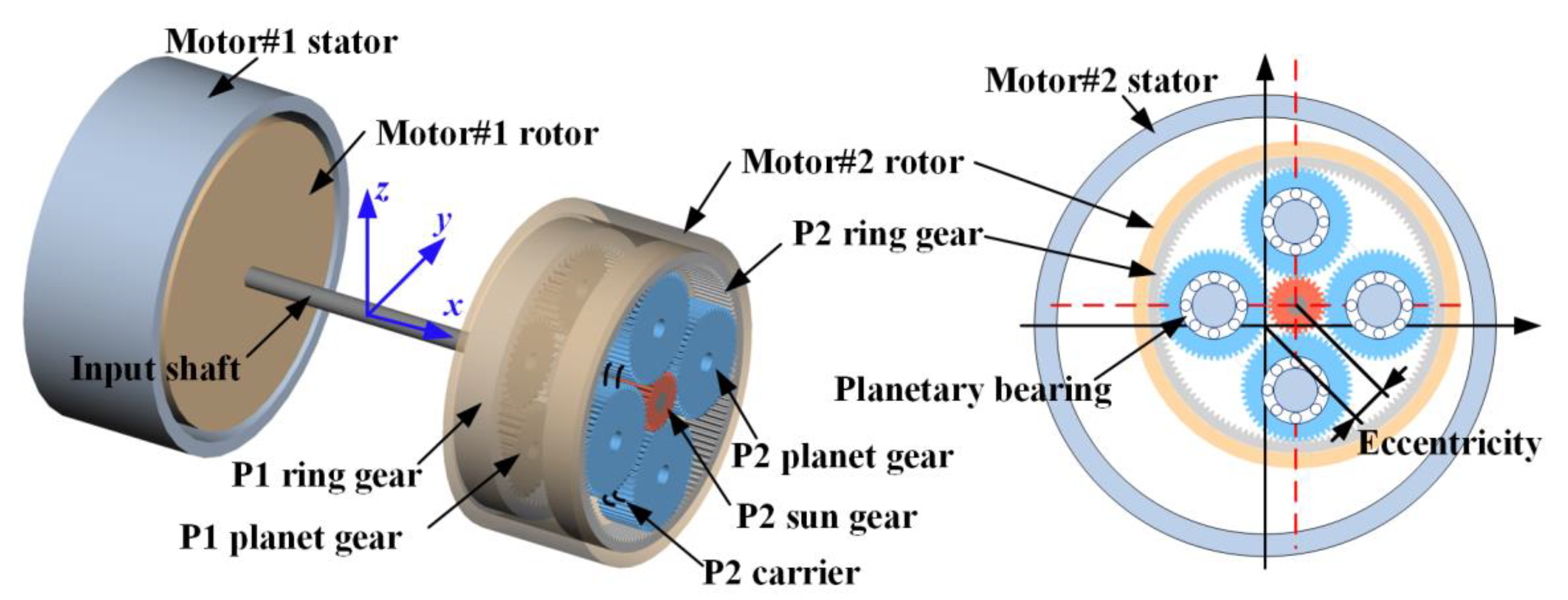
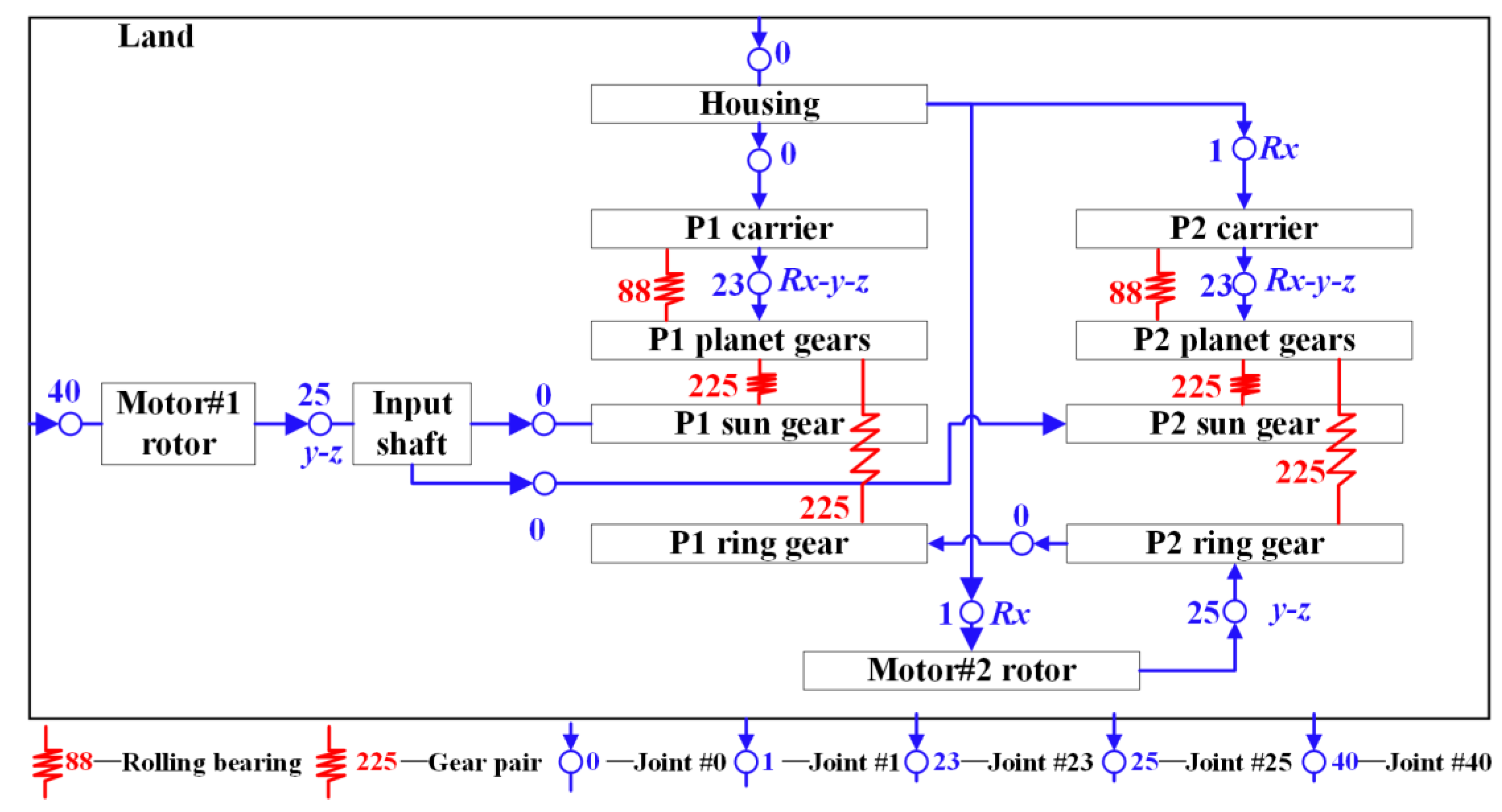
2.1. Kinematic Modeling of the DRPGS

The structure of the DRPGS studied in this paper is depicted in Figure 1. In this DRPGS, motors #1 and #2 are the power sources of the EECS. The sun gears of both rows of the DRPGS are rigidly connected to the input shaft. The two rows of the DRPGS are named P1 and P2; each row comprises the sun gear, planet gears, carrier, and ring gear. Specially, the P1 inner ring and P2 inner ring are both rigidly connected with the rotor of motor #2. According to the kinematic relationships and geometric parameters, a multibody dynamic model of the DRPGS is established. Due to the compact dimension of the DRPGS, the flexibilities in the shafts and gear bodies are ignored. The components of the DRPGS are considered as full rigid bodies.
In the Simpack multibody dynamic modeling platform, the joints are introduced to restrict the kinematic relationships between the components of the system. For the DRPGS depicted in Figure 1, the usage of the joints is detailed in Table 1. In Simpack, the land is used to represent the fixed point in the model. Joint #0 can rigidly connect the two components with the same degrees of freedom. Joint #40 can apply revolute motion on the component. Joint #23 (planar Rx-y-z) represents that one component can only revolve around the x-axis and move along the y and z-axes relative to another component. The Joint #25 (user-defined: y-z) represents that one component can only move along the y and z-axes relative to another component. The force elements 88 and 225 are used to represent the nonlinear rolling bearing forces and gear pair forces between the components. For visually displaying the dynamic modeling and simulation process of the DRPGS, the flow diagram is depicted in Figure 2.

2.2. Motion Equations of the DRPGS

The dynamic model of the DRPGS is depicted in Figure 3. According to Newton’s second law, the motion equations of DRPGS can be derived [25]
M q ¨ + C b + C m q ˙ m + K b + K m q = T ( t ) + F ( t )
where M, Kb, Km, and Cb, Cm are the mass, stiffness, and damping matrix of the system, respectively; q is the displacement vector; T(t) and F(t) are the external and internal excitation vectors, respectively.
q = x c , y c , θ c , x r , y r , θ r , x s , y s , θ s , x 1 , y 1 , θ 1 , , x n , y n , θ n
where x and y are the displacements along the x and y-axes, respectively; θ is the angular displacement; the subscripts c, r, and s represent the carrier, ring gear, and sun gear, respectively.
The detailed motion equations of the carrier are
m c x ¨ c + k p δ cnx + c p δ ˙ cnx + k c x c + c c x ˙ c = 0 m c y ¨ c + k p δ cny + c p δ ˙ cny + k c x c + c c x ˙ c = 0 ( I c / r c ) θ ¨ c + k p δ cnu + c p δ ˙ cnu + k ct θ c r c + c ct θ ˙ c r c = T c / r c
where kp and cp are the support stiffness and damping of the carrier, respectively, and rc is the distribution radius.
The detailed motion equations of the ring gear are
m r x ¨ r + k rn δ rn sin ψ rn + c rn δ ˙ rn sin ψ rn + k r x r + c r x ˙ r = 0 m r y ¨ r + k rn δ rn cos ψ rn + c rn δ ˙ rn cos ψ rn + k r x r + c r x ˙ r = 0 ( I r / r r ) θ ¨ r + k rn δ rn + c rn δ ˙ rn + k rt θ r r r + c rt θ ˙ r r r = T r / r r
where krn and crn are the meshing stiffness and damping of the ring gear, respectively, and the nth planet gear, rc is the distribution radius, and kr and cr are the support stiffness and damping, respectively.
The detailed motion equations of the sun gear are
m s x ¨ s + k sn δ sn sin ψ sn + c sn δ ˙ sn sin ψ sn + k s x s + c s x ˙ s = 0 m s y ¨ s + k sn δ sn cos ψ sn + c sn δ ˙ sn cos ψ sn + k s x s + c s x ˙ s = 0 ( I s / r s ) θ ¨ s + k sn δ sn + c sn δ ˙ sn + k st θ s r s + c st θ ˙ s r s = T s / r s
where ksn and csn are the meshing stiffness and damping of the sun gear and the nth planet gear, respectively.
The detailed motion equations of the planet gear are
m n x ¨ n + k sn δ sn sin ψ sn + c sn δ ˙ sn sin ψ sn + k rn δ rn sin ψ rn + c rn δ ˙ rn sin ψ rn k p δ cnx c p δ ˙ cnx = 0 m n y ¨ n k sn δ sn cos ψ sn c sn δ ˙ sn cos ψ sn k rn δ rn sin ψ rn c rn δ ˙ rn sin ψ rn k p δ cny c p δ ˙ cny = 0 ( I n / r n ) θ ¨ n + k sn δ sn + c sn δ ˙ sn k rn δ rn c rn δ ˙ rn = 0
The dynamic equations of rolling bearing are [26,27,28]
m b x ¨ + c x ˙ + i = 1 N b F b J ( ς i ) sin α i = 0 m b y ¨ + c y ˙ + i = 1 N b F b J ( ς i ) cos α i = 0
where mb and c are the mass of the inner ring and contact damping, respectively; J(ςi) is the determination coefficient when ςi ≥ 0, J(ςi) = 1, else J(ςi) = 0. αi is the position angle of the i-th ball; Kg is the ball-inner ring Hertzian contact stiffness; ςi is the contact deformation, which is
ς i = y sin α i + x cos α i ς 0

3. Results and Discussion

The proposed model is simulated to investigate the dynamic characteristics of the energy conversion system. The gear parameters in the DRPGS model are displayed in Table 2. The planetary bearings NJ 1005ECJ and FG 42205 are utilized to support the P1 planet gears and P2 planet gears, respectively. The detailed parameters of the bearings are plotted in Table 3. Firstly, the RMS (root mean square) values of the accelerations for system components are collected under constant torque and constant power conditions, respectively. The relationships between the system vibration and the operating speed and load torque are drawn. Then, two typical conditions are selected to study the effectiveness of the structural parameters on the reduction in the system vibration.

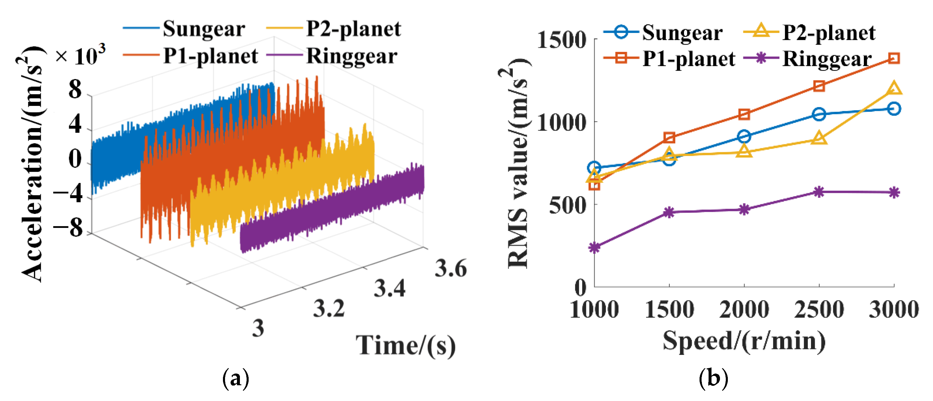
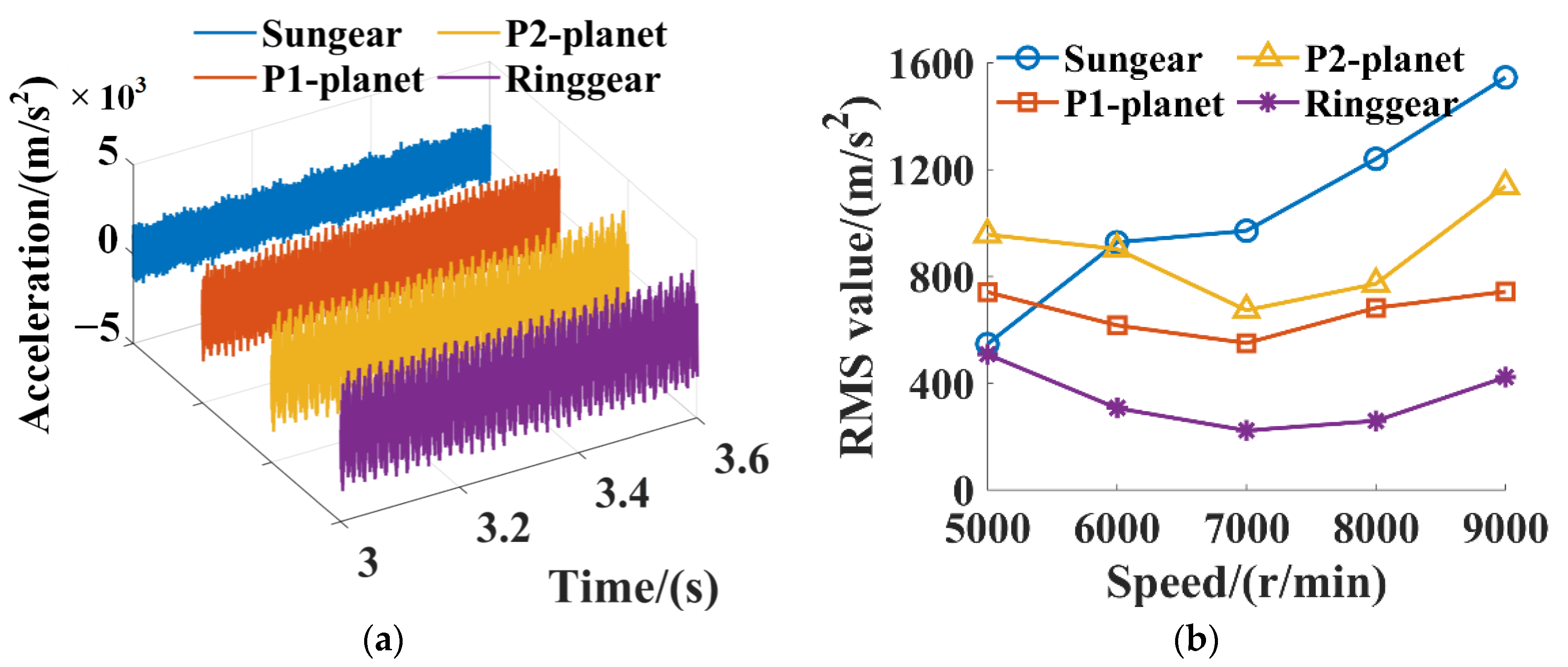
3.1. Effects of Operating Conditions on the Vibration Characteristics of the DRPGS

3.1.1. Constant Torque Condition

The energy conversion system is continuously operating within the rated power range. The load torque is kept stable at 600 Nm. The input speed of the system is changed to 1000 r/min, 1500 r/min, 2000 r/min, 2500 r/min, and 3000 r/min. The acceleration time domain waveforms of the sun gear, P1 planet gear, P2 planet gear, and ring gear at 2000 r/min are plotted in Figure 4a. There are obvious periodic oscillations due to gear engagement in the observation of the waveforms. To visually display the changing trends in the system vibration with the increase in input speed, the RMS values of the system components under different speeds are calculated and plotted in Figure 4b. As shown in Figure 4b, almost all RMS values of different system components increase consistently with the increase in input speed. Moreover, the sun gear and the planet gears vibrate more significantly than the ring gear.

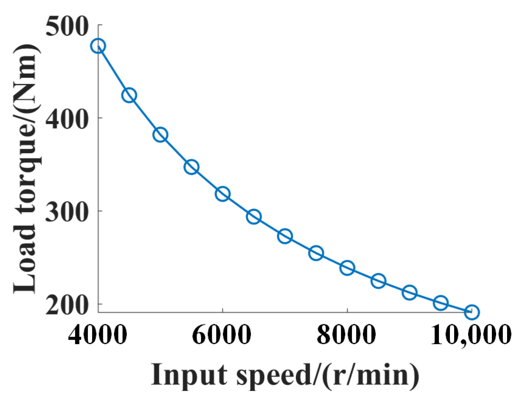
3.1.2. Constant Power Condition

As the input speed continuously increases, the system starts operating at the rated power. With the input speed change from 5000 r/min to 9000 r/min, the load torque changes to 382 Nm, 318.3 Nm, 272.8 Nm, 238.7 Nm, and 212.2 Nm, respectively. It can be observed that the input speed and load torque of the system change simultaneously but with a contrary tendency, as shown in Figure 5. The RMS values of the accelerations of system components under different speeds are calculated and plotted in Figure 6b. As shown in Figure 6b, the RMS values of the sun gear still increase with the development of the input speed. The RMS values of the P1 planet gears, the P2 planet gears, and the ring gear initially decrease before increasing alongside the continuing increase in the input speed. With the input speed change from 5000 r/min to 7000 r/min, the load torque of the system drastically decreases from 382 Nm to 272.8 Nm, a decrease of 109.2 Nm. As the input speed continuously changes from 7000 r/min to 9000 r/min, the load torque of the system changes from 272.8 Nm to 212.2 Nm, a decrease of 60.6 Nm. This indicates that the RMS values of the system components decrease due to the drastic decrease in the load torque at lower speeds. With the steady improvement in input speed, the decrease in the load torque becomes decent, and the RMS values of the system turn to increase.
To sum up, the components in the system vibrate more significantly with the increase in input speed at constant torque conditions. While the levels of vibrations for the system components decrease first, the levels subsequently increase with the input speed at constant power conditions. Then, a total of two typical conditions (3000 r/min and 9000 r/min) are separately selected from the constant torque and constant power conditions to further investigate the effectiveness of the structural parameters on the alleviation of the system vibration.

3.2. Effects of Structural Parameters on the Vibration Characteristics of the DRPGS

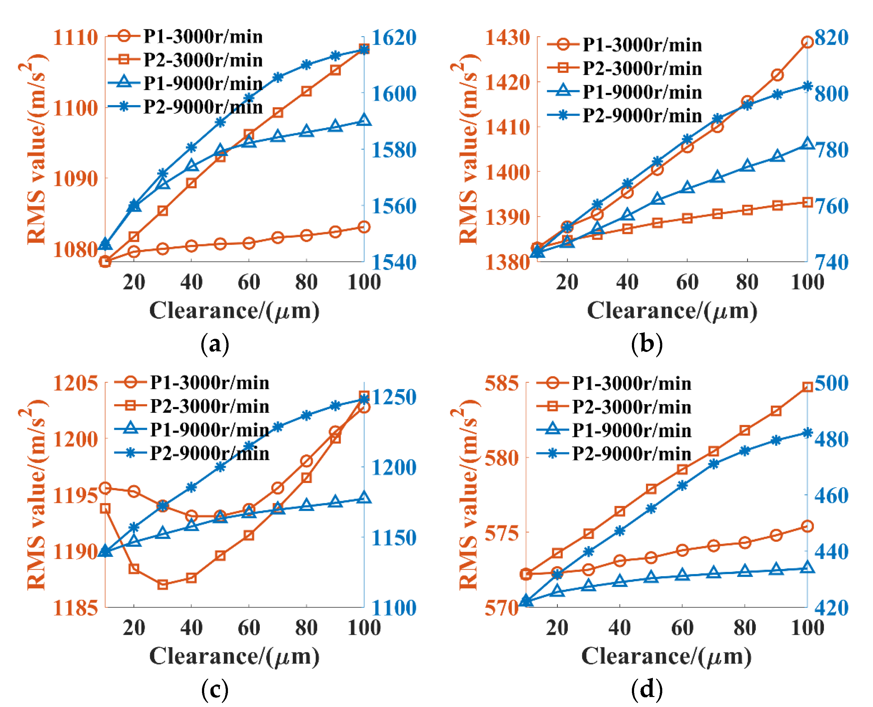
3.2.1. Effects of Bearing Clearances

To study the effectiveness of the bearing clearances on the reduction of the system vibration. The RMS values of the accelerations for components with different bearing clearances at 3000 r/min and 9000 r/min are gathered. The clearances for the P1 planet gear bearings and P2 planet gear bearings were changed from 10 μm to 100 μm, respectively. The RMS values of the accelerations for the sun gear, P1 planet gear, P2 planet gear, and ring gear are plotted in Figure 7a, Figure 7b, Figure 7c, and Figure 7d, respectively. In each subpart of Figure 7, there are four curves, and the legend ‘P1-3000 r/min’ indicates the RMS values of the components with the change in the clearances of the P1 planet gear bearing at an input speed of 3000 r/min. As shown in Figure 7, except for the P2 planet gear, the RMS values of the sun gear, P1 planet gear, and ring gear all increase steadily with the bearing clearances. In Figure 7c, the RMS values of the P2 planet gears decrease first and then increase with the increase in clearances for the P1 and P2 planet gear bearings at 3000 r/min. However, the RMS values fluctuate within 10 m/s2 and this may be caused by the computational convergence error.
Moreover, the RMS values of the system components at 9000 r/min increase more significantly with the bearing clearances compared to those for the system components at 3000 r/min. Once the bearing clearances exceed 40 μm, the growth slope of the RMS values begins to slow down. The results demonstrate that the bearing clearance indeed influences the system vibration. Improving the manufacturing precision and matching quality can be beneficial to controlling the system vibration. For the energy conversion system in this study, the bearing clearances should be limited below 40 μm.

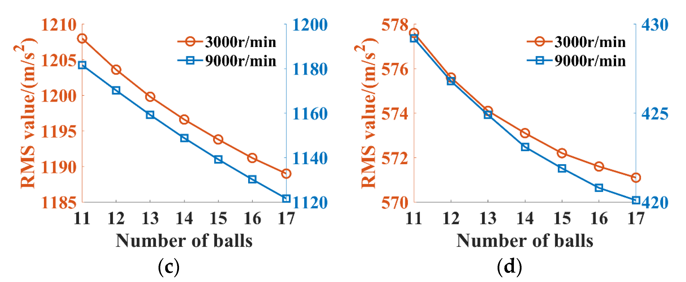
3.2.2. Effects of Bearing Ball Numbers

The number of balls for the bearings of P1 planet gear was changed from 11 to 17. The RMS values of the system components at 3000 r/min and 9000 r/min were gathered and are plotted in Figure 8a–d. As shown in Figure 8, the RMS values of the accelerations for system components all decrease with the increase in ball numbers for the bearings of the P1 planet gear. Compared to the RMS values of the sun gear and ring gear, the RMS values of the accelerations for the P1 planet gear and P2 planet gear decrease more significantly. Moreover, the changing trends in the RMS values of the accelerations for the P1 planet gear are steeper than those for the P2 planet gear. These results indicate that increasing the number of balls in the bearing of the P1 planet gear can be effective in reducing the system vibration.
Similarly, the number of balls for the bearings of the P2 planet gears also changed from 8 to 14. The RMS values of the system components at 3000 r/min and 9000 r/min were gathered and are plotted in Figure 9a–d. As shown in Figure 9, the same relationships between the RMS values of the accelerations for system components and the number of balls can be observed. Moreover, the results indicate that changing the number of balls for the bearings of the P2 planet gear is more effective than changing the number of balls for the bearings of the P1 planet gear in reducing the system vibrations.

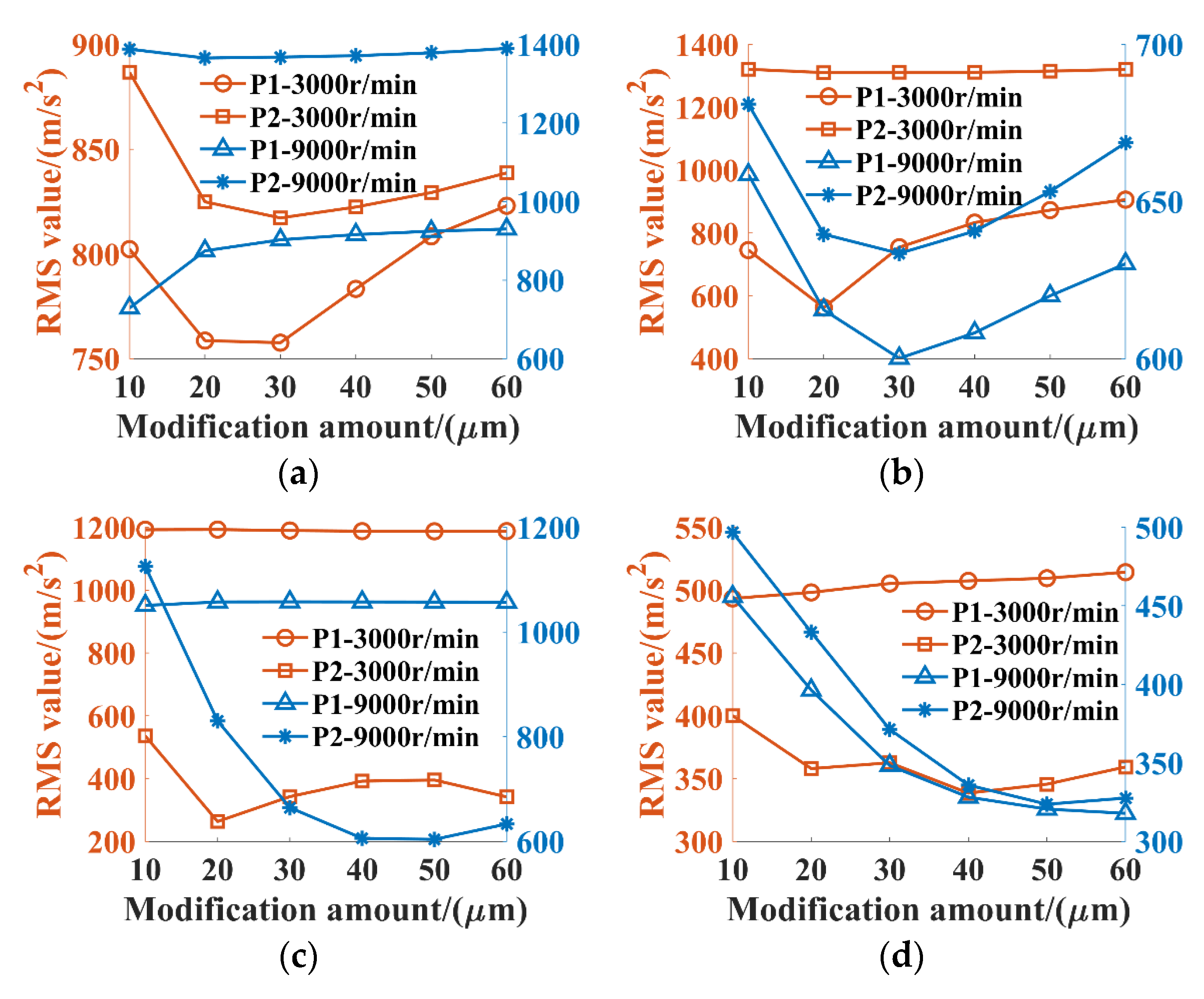
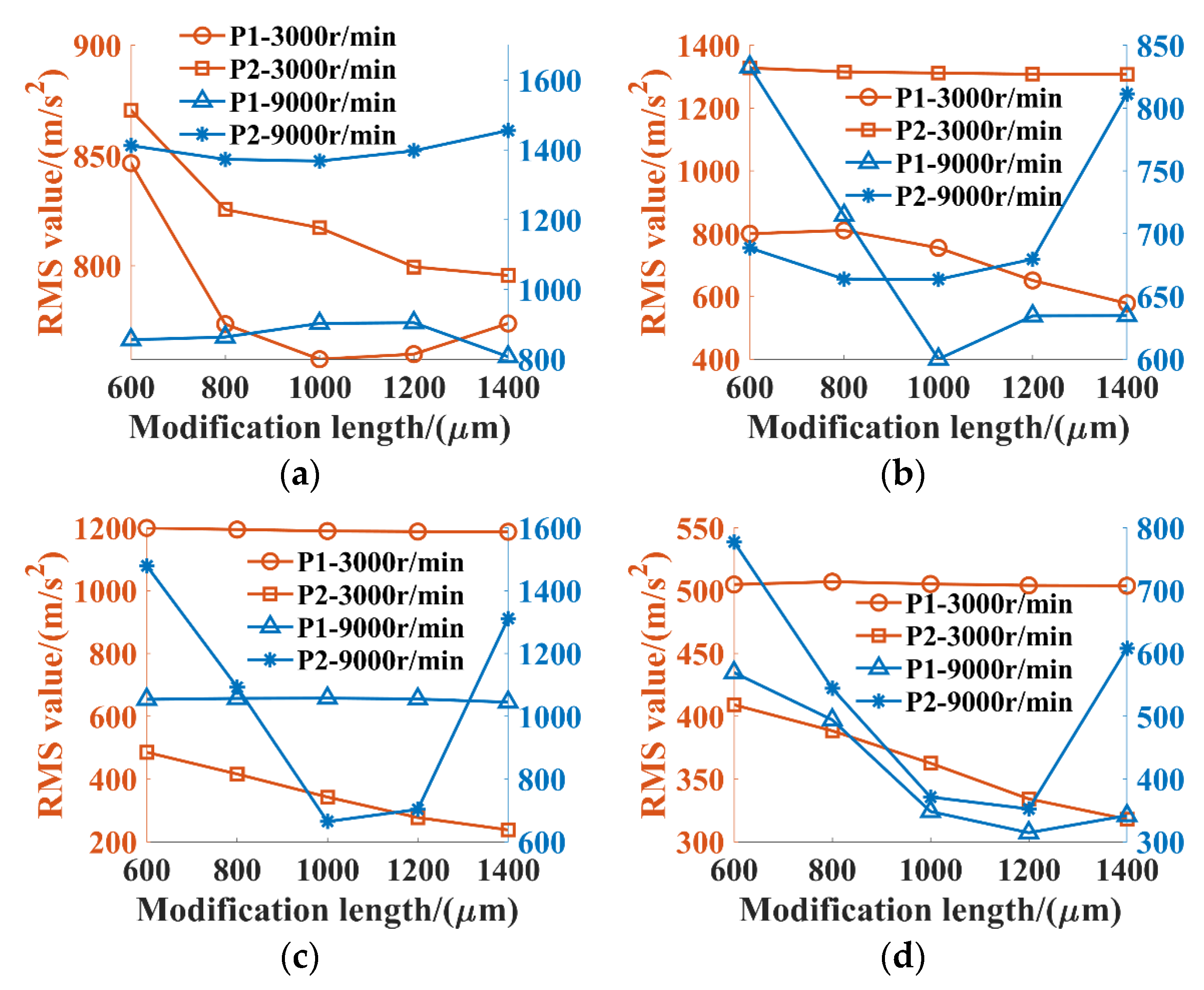
3.2.3. Effects of Gear Tooth Modification

The RMS values of the accelerations for the system components with different modification amounts and lengths of the P1 planet gears and P2 planet gears were collected to study the effectiveness of the gear tooth modification on the suppression of the system vibration. The schematic of the gear tooth with profile modification is shown in Figure 10. The modification amounts of the P1 planet gear and P2 planet gear were changed from 10 μm to 60 μm, respectively. The relationships between the RMS values of accelerations for different system components and the modification amounts are plotted in Figure 11. As shown in Figure 11, the modification amounts have a small impact on the vibrations of the sun gear. The RMS values of accelerations for the P1 planet gear first decrease and then increase with the modification amount at an input speed of 9000 r/min, while those of the P1 planet gear slightly change with the modification amount at an input speed of 3000 r/min. Moreover, changing the modification amounts of the P1 planet gears has a more significant influence on the vibrations of the P1 planet gears than changing the modification amounts of the P2 planet gears.
For the P2 planet gear, the RMS values of the accelerations also slightly change with the developments in the modification amounts for the P1 planet gear. The influences of the modification amount of the P2 planet gears were also found to be more significant at an input speed of 9000 r/min than those at an input speed of 3000 r/min. The RMS values of the accelerations for the P2 planet gear at 9000 r/min first decrease and then increase with the modification amounts; the RMS values reach a minimum when the modification amounts are 40 μm. A similar phenomenon can be observed on the RMS values of the accelerations for the ring gear; the influences of the modification amounts of the P1 and P2 planet gears are more significant with an input speed of 9000 r/min. The RMS values of the accelerations for the ring gear first decrease and then increase with the modification amounts. Then, the above results indicate that the appropriate modification amounts can indeed suppress the system vibrations.
The modification lengths of the P1 planet gear and P2 planet gear were changed from 600 μm to 1400 μm, respectively. The RMS values of accelerations for each system component with different modification lengths were simulated and are plotted in Figure 12. As shown in Figure 12a, the modification lengths have a small impact on the vibrations of the sun gear at 9000 r/min. Meanwhile, the RMS values of the sun gear steadily decrease with the increase in modification lengths at 3000 r/min. This may indicate that the modification lengths have more significant influences on the vibration of the sun gear under higher load torque conditions. As shown in Figure 12b–d, the modification lengths indeed decrease the RMS values of the P1 planet gear, P2 planet gear, and ring gear. However, the RMS values fluctuate with the increase in modification lengths at 9000 r/min compared to the steady decreased tendency of the RMS values at 3000 r/min. As plotted in Figure 12b, the RMS values of the accelerations for the P1 planet gear first decrease and then increase with the increase in the modification lengths at 9000 r/min, and the minimum RMS value is reached when the modification length is 1000 μm.
As depicted in Figure 12c, the RMS values of the accelerations for the P2 planet gear with different P1 planet gear modification lengths are slightly changed. Moreover, the RMS values of the accelerations for the P2 planet gear fluctuate more significantly with the modification lengths of the P2 planet gear. At the input speed of 3000 r/min, the RMS values of the accelerations for the P2 planet gear gradually decrease with the increase in the modification lengths while those decrease first and increase subsequently with the modification lengths at an input speed of 9000 r/min. The minimum RMS value is also reached when the modification length is 1000 μm. As depicted in Figure 12d, a similar phenomenon can be observed on the RMS values of the accelerations for the ring gear; the RMS values rapidly decrease with the modification lengths at 3000 r/min, and the effects of the P2 planet gear’s modification lengths are more significant than those of the P1 planet gear’s modification lengths. At the input speed of 9000 r/min, the RMS values of the accelerations for the ring gear decrease first and increase subsequently with the modification lengths. The minimum RMS value is reached when the modification length is 1200 μm. The above results indicate that moderate modification lengths can be effective in the suppression of the system vibrations.

4. Conclusions

In this paper, a dynamic model of the DRPGS for an EECS is established on the multibody dynamic modeling platform of Simpack. Based on the kinetic relationship between the gear pairs and bearing components, the dynamic equations of the DRPGS are derived. The DRPGS model under different operating conditions is simulated, and the relationships between the system vibration, the operating speed, and load torque are revealed. The structural parameters, including bearing clearance, ball numbers, gear tooth modification amount, and length, are introduced, and their effectiveness in the vibration control of the DRPGS is discussed. Some conclusions can be drawn:
(1)
The vibrations of the components in the DRPGS increase with the input speed at constant torque conditions. The levels of vibrations for the DRPGS components decrease firstly, then increase with the input speed at constant power conditions. It indicates that the vibrations of the DRPGS are more sensitive to the load torque at low-speed conditions.
(2)
The bearing clearance indeed has influences on the system vibration. Improving the manufacturing precision and matching quality can be beneficial to controlling the system vibration.
(3)
An increase in the number of balls of the planet gear bearings can be effective in reducing the system vibration and changing the number of balls for the P2 planet gear bearings is more effective.
(4)
Both the modification amounts and lengths have more significant influences on the system vibration at 9000 r/min than those at 3000 r/min. The appropriate modification amounts and lengths can indeed suppress the system vibrations, the modification amount for this DRPGS should be within the range of 20 μm to 40 μm; the modification amount for this DRPGS was chosen in the range of 1000 μm to 1200 μm.

Author Contributions

Writing—original draft preparation, X.L.; simulation analyses, Y.X.; in charge of the whole trial, J.L.; review and editing of the manuscript, W.W. All authors have read and agreed to the published version of the manuscript.

Funding

This research was funded by Guangdong Basic and Applied Basic Research Foundation (2024A1515011126); National Key Research and Development Plan of China (2023YFB3406302); National Natural Science Foundation of China (52175120).

Data Availability Statement

These datasets are available from the corresponding author upon reasonable request.

Conflicts of Interest

The authors declare no competing financial interests.

References

  1. Bai, Z.; Ning, Z. Dynamic responses of the planetary gear mechanism considering Dynamic wear effects. Lubricants 2023, 11, 255. [Google Scholar] [CrossRef]
  2. He, G.; Ding, K.; Wu, X.; Yang, X. Dynamics modeling and vibration modulation signal analysis of wind turbine planetary gearbox with a floating sun gear. Renew. Energy 2019, 139, 718–729. [Google Scholar] [CrossRef]
  3. Liu, J.; Li, X.; Xia, M. A dynamic model for the planetary bearings in a double planetary gear set. Mech. Syst. Signal. Process. 2023, 194, 110257. [Google Scholar] [CrossRef]
  4. Xu, X.; Fan, X.; Diao, P.; Liu, H. An investigation on the influence of modification parameters on transmission characteristics of planetary gear system. J. Mech. Sci. Technol. 2019, 33, 3105–3114. [Google Scholar] [CrossRef]
  5. Chen, X.; Hu, Q.; Xu, Z.; Zhu, C. Numerical modeling and dynamic characteristics study of coupling vibration of multistage face gearsplanetary transmission. Mech. Sci. 2019, 10, 475–495. [Google Scholar] [CrossRef]
  6. Qiu, W.; Yang, F.; Wang, D.; Jiang, X. Design and free vibration characteristics of linkage planetary gear trains. J. Braz. Soc. Mech. Sci. 2022, 44, 58. [Google Scholar] [CrossRef]
  7. Wang, C.; Parker, R. Nonlinear dynamics of lumped-parameter planetary gears with general mesh phasing. J. Sound Vib. 2022, 523, 116682. [Google Scholar] [CrossRef]
  8. Dai, H.; Wang, Y.; Luo, S.; Li, Y.; Zi, B. Dynamic modeling and vibration analysis of planetary gear sets concerning mesh phasing modulation. Mech. Syst. Signal. Process. 2023, 200, 110557. [Google Scholar] [CrossRef]
  9. Zhang, J.; Guo, H.; Yu, H.; Zhang, T. Numerical and experimental investigation on nonlinear dynamic characteristics of planetary gear train. J. Theor. App. Mech. 2020, 58, 1009–1022. [Google Scholar] [CrossRef]
  10. Mo, S.; Huang, X.; Liu, W.; Zhang, W. Study on nonlinear vibration and primary resonance characteristics of helicopter face gear-planetary gear coupling transmission system. Proc. Inst. Mech. Eng. Part K J. Multi-Body Dyn. 2023, 237, 534–554. [Google Scholar] [CrossRef]
  11. Sun, Z.; Chen, S.; Hu, Z.; Lei, D. Vibration response analysis of a gear-rotor-bearing system considering steady-state temperature. Nonlinear Dynam. 2022, 107, 477–493. [Google Scholar] [CrossRef]
  12. Lai, J.; Liu, Y.; Xu, X.; Li, H.; Xu, J.; Wang, S.; Guo, W. Dynamic modeling and analysis of Ravigneaux planetary gear set with unloaded floating ring gear. Mech. Mach. Theory 2022, 170, 104696. [Google Scholar] [CrossRef]
  13. Tatar, A.; Schwingshackl, C.; Friswell, M. Modal sensitivity of three-dimensional planetary geared rotor systems to planet gear parameters. Appl. Math. Model. 2023, 113, 309–332. [Google Scholar] [CrossRef]
  14. Fan, Z.; Zhu, C.; Song, C. Dynamic analysis of planetary gear transmission system considering the flexibility of internal ring gear. Iran. J. Sci. Technol. Trans. Mech. Eng. 2020, 44, 695–706. [Google Scholar] [CrossRef]
  15. Hu, A.; Liu, S.; Xiang, L.; Zhang, Y. Dynamic modeling and analysis of multistage planetary gear system considering tooth crack fault. Eng. Fail. Anal. 2022, 137, 106408. [Google Scholar] [CrossRef]
  16. Li, X.; Liu, J.; Xu, J.; Chen, Y.; Hu, Z.; Pan, G. A vibration model of a planetary bearing system considering the time-varying wear. Nonlinear Dynam. 2023, 111, 19817–19840. [Google Scholar] [CrossRef]
  17. Li, X.; Liu, J.; Ding, S.; Xu, Y.; Zhang, Y.; Xia, M. Dynamic modeling and vibration analysis of double row cylindrical roller bearings with irregular-shaped defects. Nonlinear Dynam. 2024, 112, 2501–2521. [Google Scholar] [CrossRef]
  18. Yang, H.; Li, X.; Xu, J.; Yang, Z.; Chen, R. Dynamic characteristics analysis of planetary gear system with internal and external excitation under turbulent wind load. Sci. Prog. 2021, 104, 00368504211035604. [Google Scholar] [CrossRef] [PubMed]
  19. Cheng, G.; Ma, J.; Li, J.; Sun, K.; Wang, K.; Wang, Y. Study on the Dynamic Characteristics of Gears Considering Surface Topography in a Mixed Lubrication State. Lubricants 2023, 12, 7. [Google Scholar] [CrossRef]
  20. Xu, H.; Ren, H.; Qin, D. Dynamic characteristics of the planetary gear system with rolling bearing. Multibody Syst. Dyn. 2023, 59, 171–191. [Google Scholar] [CrossRef]
  21. Geng, Z.; Li, J.; Xiao, K.; Wang, J. Analysis on the vibration reduction for a new rigid–flexible gear transmission system. J. Vib Control 2022, 28, 2212–2225. [Google Scholar] [CrossRef]
  22. Wang, P.; Xu, H.; Ma, H.; Han, Z.; Yang, Y. Effects of three types of bearing misalignments on dynamic characteristics of planetary gear set-rotor system. Mech. Syst. Signal. Process. 2022, 169, 108736. [Google Scholar] [CrossRef]
  23. Xin, W.; Zhang, Y.; Fu, Y.; Yang, W.; Zheng, H. A multi-objective optimization design approach of large mining planetary gear reducer. Sci. Rep. 2023, 13, 18640. [Google Scholar] [CrossRef] [PubMed]
  24. Öztürk, V.; Cigeroglu, E.; Özgüven, H. Ideal tooth profile modifications for improving nonlinear dynamic response of planetary gear trains. J. Sound Vib. 2021, 500, 116007. [Google Scholar] [CrossRef]
  25. Zhang, K.; Shao, Y.; Galar, D. The dynamic response of a planetary gear train in the presence of a spalling fault. In Proceedings of the Intelligent Technologies for Equipment and Human Performance Monitoring (MFPT 2018), Virginia Beach, VA, USA, 15–17 May 2018; Society for Machinery Failure Prevention Technology: Dresher, PA, USA, 2018; pp. 252–266. [Google Scholar]
  26. Zhang, C.; Yu, W.; Zhang, Y.; Xu, J.; Zeng, Q.; Li, L.; Wang, L.; Huang, W. Dynamics modeling and analysis of the multistage planetary gear set-bearing-rotor-clutch coupling system considering the tooth impacts of clutches. Mech. Syst. Signal. Process. 2024, 214, 111365. [Google Scholar] [CrossRef]
  27. Liu, J.; Ni, H.; Zhou, R.; Li, X.; Xing, Q.; Pan, G. A simulation analysis of ball bearing lubrication characteristics considering the cage clearance. J. Tribol. 2023, 145, 044301. [Google Scholar] [CrossRef]
  28. Zhang, C.; Hu, Y.; Gu, Y.; Dong, H. Assembly accuracy prediction method of planetary gear train considering bolt-bearing-shaft-gear coupling effects. Appl. Math. Model. 2024, 131, 403–422. [Google Scholar] [CrossRef]
Figure 1. Schematic of the planetary gear system of the energy conversion system.
Lubricants 12 00211 g001
Figure 2. Flow diagram of the dynamic modeling of the DRPGS.
Lubricants 12 00211 g002
Figure 3. A dynamic model of the DRPGS.
Lubricants 12 00211 g003
Figure 4. Simulation results of (a) the acceleration time domain waveforms at 2000 r/min and (b) acceleration RMS values at different speeds under constant torque conditions.
Lubricants 12 00211 g004
Figure 5. Relationships between the system input speed and load torque under constant power conditions.
Lubricants 12 00211 g005
Figure 6. Simulation results of (a) the acceleration time domain waveforms at 5000 r/min and (b) acceleration RMS values at different speeds under constant power conditions.
Lubricants 12 00211 g006
Figure 7. Effects of bearing clearances on the RMS values of accelerations for (a) sun gear, (b) planet gear of P1, (c) planet gear of P2, and (d) ring gear.
Lubricants 12 00211 g007
Figure 8. Effects of ball numbers of the P1 planet gear bearing on the RMS values of accelerations for (a) sun gear, (b) planet gear of P1, (c) planet gear of P2, and (d) ring gear.
Lubricants 12 00211 g008aLubricants 12 00211 g008b
Figure 9. Effects of ball numbers of the P2 planet gear bearing on the RMS values of accelerations for (a) sun gear, (b) planet gear of P1, (c) planet gear of P2, and (d) ring gear.
Lubricants 12 00211 g009
Figure 10. Schematic of the gear tooth with profile modification.
Lubricants 12 00211 g010
Figure 11. Effects of modification amounts on the RMS values of accelerations for (a) sun gear, (b) planet gear of P1, (c) planet gear of P2, and (d) ring gear.
Lubricants 12 00211 g011
Figure 12. Effects of modification lengths on the RMS values of accelerations for (a) sun gear, (b) planet gear of P1, (c) planet gear of P2, and (d) ring gear.
Lubricants 12 00211 g012
Table 1. Usage of the joints.
From ComponentTo ComponentJoint Type
LandHousingJoint #0 (0 degrees of freedom)
LandMotor #1 rotorJoint #40 (single-axis u(t))
Motor #1 rotorInput shaftJoint #25 (user-defined: y-z)
Input shaftP1 sun gearJoint #0
Input shaftP2 sun gearJoint #0
HousingP1 carrierJoint #0
P1 carrierP1 planet gearsJoint #23 (planar Rx-y-z)
HousingMotor #2 rotorJoint #1 (revolute Rx)
P2 ring gearP1 ring gearJoint #0
Motor #2 rotorP2 ring gearJoint #25 (user-defined: y-z)
HousingP2 carrierJoint #1 (revolute Rx)
P2 carrierP2 planet gearsJoint #23 (planar Rx-y-z)
Table 2. Gear parameters in the DRPGS model.
ParametersP1
Sun Gear
P1
Planet Gear
P1
Ring Gear
P2
Sun Gear
P2
Planet Gear
P2
Ring Gear
Number of teeth2728832753133
Modulus333222
Width/mm40
Pressure
angle/°
20
Modification
coefficient
0.0138−0.01380.01380.1893−0.18930.1893
Material40Cr
Table 3. Bearing parameters in the DRPGS model.
ParametersNJ 1005ECJFG 42205
Bore diameter/mm2525
Outside diameter/mm4752
Width/mm11.914.88
Inner raceway diameter/mm30.431.42
Outer raceway diameter/mm40.8846.06
Number of rolling elements1512
Roller diameter/mm5.247.32
Roller effective length/mm5.78.78
Disclaimer/Publisher’s Note: The statements, opinions and data contained in all publications are solely those of the individual author(s) and contributor(s) and not of MDPI and/or the editor(s). MDPI and/or the editor(s) disclaim responsibility for any injury to people or property resulting from any ideas, methods, instructions or products referred to in the content.

