Article

Thermo-Fluid–Structural Coupled Analysis of a Mechanical Seal in Extended Loss of AC Power of a Reactor Coolant Pump

1
Department of Mechanical Convergence Engineering, Hanyang University, Seoul 04763, Republic of Korea
2
Department of Engineering, Flowserve KSM, Gimpo 10040, Republic of Korea
*
Author to whom correspondence should be addressed.
Lubricants 2024, 12(6), 212; https://doi.org/10.3390/lubricants12060212
Submission received: 3 May 2024 / Revised: 3 June 2024 / Accepted: 6 June 2024 / Published: 10 June 2024
(This article belongs to the Special Issue Mechanical Tribology and Surface Technology)

Abstract

:
We proposed a numerical method to investigate the thermo-fluid–structural coupled characteristics of a mechanical seal of a reactor coolant pump (RCP), especially during extended loss of AC power (ELAP) operation. We developed a finite element program for the general Reynolds equation, including the turbulence effect to calculate the pressure, opening force, and leakage rate of fluid lubricant and the two-dimensional energy equation to calculate the temperature distribution of the fluid lubricant. We verified the accuracy of the developed program by comparing the simulated temperature distribution and leakage rate of this study with those of previous research. Heat conduction and elastic deformation due to pressure and temperature changes at the seal structure were analyzed using an ANSYS program. The results showed that temperature more significantly affected the elastic deformation of the seal structure near clearance than pressure both under normal and ELAP operating conditions. High temperature and pressure of the coolant under ELAP operating conditions deform the seal structure, resulting in a much smaller clearance of the fluid film than normal operating condition. However, even with a small clearance under ELAP operation, the leakage rate slightly increases due to the high internal pressure of the coolant. This research will contribute to the development of robust mechanical seals for RCPs by accurately predicting the characteristics of mechanical seals, especially when the RCP is operating under ELAP.

1. Introduction

A reactor coolant pump (RCP) used in a pressurized water reactor of a nuclear power plant is a device that circulates pressurized water coolant between the reactor and the steam generator. To prevent leakage of the coolant, a three-stage cartridge-type mechanical seal is applied to the RCP. Under normal operating conditions of the RCP, the coolant temperature is around 40 °C, and the total pressure reduction through the three-stage mechanical was around 150 bar, where the high pressure of the coolant was roughly distributed to three mechanical seals with a distribution of 42% (63 bar reduction), 42% (63 bar reduction), and 16% (24 bar reduction). However, with extended loss of AC power (ELAP), the coolant temperature is over 300 °C, and a single stage of the mechanical seal has to be safely operated to withstand a high-pressure difference of 150 bar. It is important to predict the leakage and the seal deformation of the mechanical seal in the design stage to prevent leakage of coolant under the high-pressure and high-temperature conditions of ELAP [1]. Figure 1 illustrates the structure of the mechanical seal of an RCP, consisting of a seal that rotates with the shaft and a stationary seal attached to the housing. Either a stationary or a rotating seal has grooves to generate pressure. During operation, the mechanical seal balances the closing force exerted by external pressure and spring force with the opening force generated by the pressure in the fluid film. The behavior of the fluid film can be determined by the Reynolds equation, where the viscosity of the lubricant is mainly dependent on temperature. Pressure and leakage vary depending on the state of the fluid, the thickness of the fluid film, and surrounding pressure. The thermal energy generated in the fluid film affects the temperature of the fluid film and the surrounding structures through conduction and convection, and the structural deformation of the seal due to temperature and pressure influences the behavior of the fluid film. Therefore, an accurate calculation of the leakage from the mechanical seal requires a coupled analysis that considers the pressure and temperature distribution of the fluid film and the elastic deformation of the seal structure.
Several researchers have analyzed the performance of mechanical seals through thermo-hydrodynamic analysis. Thomas et al. analyzed the pressure, temperature, and leakage rate by solving the Reynolds equation and the energy equation to study the performance of mechanical face seals operating under high pressure. They suggested that this calculation required consideration of heat transfer of the fluid film for a stable design of seals under high pressure [2,3]. Other researchers also predicted the performance of seals by analyzing the pressure and temperature of the fluid film through thermo-hydrodynamic analysis [4,5,6,7,8]. However, they did not consider the changes in clearance caused by elastic deformation of the seal structure occurring at high a temperature and pressure. Brunetiere et al. proposed a method to analyze a mechanical face seal, including the structural thermal deformation under normal operating conditions of 40 °C and a pressure difference of 20 bar, in addition to solving the two-dimensional Reynolds equation and the three-dimensional energy equation. They showed that the calculation of leakage without considering structural thermal deformation can lead to significant error [9,10,11]. Other researchers also investigated the performance of a mechanical seal considering structural thermal deformation to accurately calculate the leakage rate of the seals in mechanical devices [12,13,14].
Galenne et al. proposed an elasto-hydrodynamic model to analyze the failure of the seals for an RCP under normal steady operating conditions at 50 °C and a total pressure difference of 150 bar [15]. They compared the simulated leakage rates from the elastic deformation of seals by solving the two-dimensional Reynolds equation and the three-dimensional energy equation and comparing the structural analysis with the experimental values. Moreover, they investigated lubrication characteristics by including the effects of structural heat transfer and elastic deformation. However, they did not consider harsh operating conditions. Su et al. proposed a coupled thermo-fluid–structural model to analyze the lubrication characteristics of wavy pattern grooved seals for an RCP under three temperatures (20 °C, 40 °C, 75 °C) and pressures (53 bar, 106 bar, 159 bar) [16]. They showed that the elastic deformation of the seals due to pressure and temperature affected the leakage rates of mechanical seals, with leakage rates increasing as the sealing pressure increased. Other researchers have also conducted a thermo-elasto-hydrodynamic analysis of the lubrication characteristics of seals for RCPs [17,18,19,20]. However, prior researchers did not investigate the effects of the high temperature and pressure of ELAP operating conditions on the performance of RCP seals.
In this study, we proposed a thermo-fluid–structural coupled analysis method to predict the pressure and temperature distributions, the change in the clearance of fluid film due to elastic deformation of the mechanical seal, and the resulting leakage rate under normal and ELAP operating conditions of an RCP. We developed the finite element program of the general Reynolds equation, including the turbulence effect to calculate the pressure, opening force, and leakage rate of fluid lubricant and the two-dimensional energy equation to calculate the temperature distribution of the fluid lubricant. The accuracy of the developed program was verified by comparing the simulated temperature distribution and leakage rate with those of the previous research. Heat conduction and elastic deformation of the seal structure due to pressure and temperature change were analyzed using the ANSYS program. The proposed method was used to investigate the lubricating characteristics of the mechanical seal under normal and ELAP conditions of the RCP.

2. Method of Analysis

2.1. Lubrication Analysis in Fluid Film

The two-dimensional Reynolds equation can be derived from the three-dimensional Navier–Stokes equation and the continuity equation with the assumption of incompressible laminar flows. By neglecting body force, inertia force, and the pressure gradient along the direction of film thickness, the two-dimensional Reynolds equation is derived to calculate the pressure of thin film flow. In fluid between two plates, the fluid state changes from laminar to turbulent condition when the Reynolds number is greater than about 1000, and the turbulent effect becomes significant as the Reynolds number increases [21,22]. Hirs proposed the general Reynolds equation in Equation (1) to model the turbulence occurring in thin-film flow [21,22].
r G r h 3 μ p r + r θ G θ h 3 μ p r θ = U 2 h r θ
Here, h , μ , p , U , G r , and G θ represent the film thickness, viscosity coefficient, pressure, velocity of the fluid, and the flow rate coefficients in the radial and circumferential directions, respectively, and they are the functions of r and θ . The flow rate coefficients vary depending on the state of the fluid. For laminar flow, these coefficients are 12 in both radial and circumferential directions; for turbulent flow, they are 0.0392 R e 0.75 and 0.0687 R e 0.75 , where Re is the Reynolds number. The film thickness varies depending on the deformation of the seal structure and can be expressed as shown in Equation (2).
h = h c + h g + h d
where h c , h g , and h d represent the minimum film thickness, groove depth, and elastic deformation of the seal face, respectively. The internal and external boundary conditions of the Reynolds equation are described in Equation (3). The external boundary conditions are applied to the inner radius and the outer radius. The periodic boundary condition implies that the pressure is continuous along the circumferential direction.
p ( r = r i , θ ) = p i p ( r = r o , θ ) = p o p ( r , θ ) = p ( r , θ + 2 π )
Here, pi and po represent the internal and external pressures, respectively.
To develop the finite element formulation of the Reynolds equation, a weighting function is multiplied; partial integration is performed, and Green’s theorem is employed to yield the following expression.
Ω G r h 3 μ w r p r + G θ h 3 μ w r θ p r θ d Ω Ω U h 2 w r θ d Ω = 0
where Ω and w represent the interested domain and weighting function, respectively. The pressure of a four-node element can be defined through the nodal pressure P e , arbitrary vector η e , and shape function N and is expressed as shown in Equations (5) and (6).
p = N T P e
w = η e T N
By substituting Equations (5) and (6) into Equation (4), the following local finite-element equation is produced:
η e T Ω G r h 3 μ N r N T P e r + G θ h 3 μ N r θ N T P e r θ d Ω η e T Ω U h 2 N r θ d Ω = 0
Equation (7) can be rewritten by introducing the local element stiffness matrices and load vectors, as shown in Equations (8)–(10):
K e P e = F e
K e = Ω G r h 3 μ N r N T r + G θ h 3 μ N r θ N T r θ d Ω
F e = Ω U h 2 N r θ d Ω
Assembling the local finite element equations to construct the global finite element equation, applying the boundary condition, and solving the global finite element equation, we can determine the pressure of the fluid film. Then, the opening force, leakage rate, and heat generation can be calculated, as shown in Equations (11)–(13) [21,22].
F o p e n = 0 2 π r i r o p r d r d θ
Q = 0 2 π G r h 3 μ p r r d θ
H = r i r o 0 2 π h 2 p r θ + μ U h r d θ d r × r ω

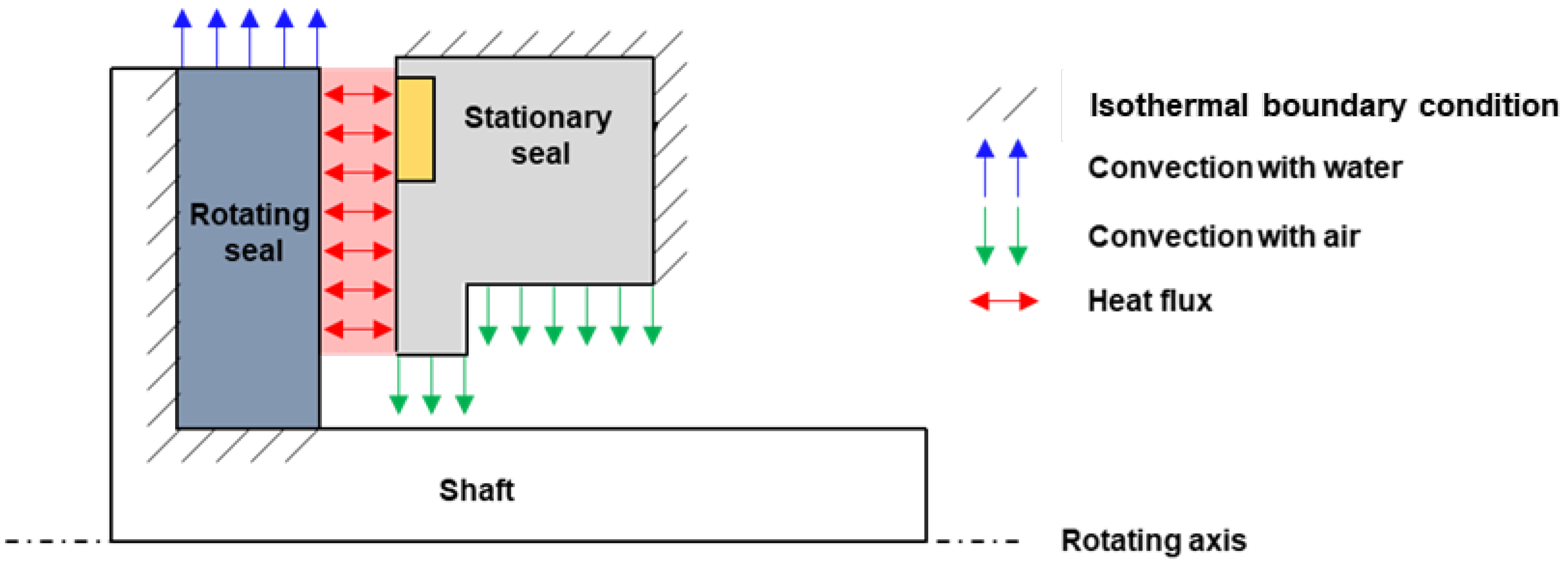
2.2. Thermal Analysis in Fluid Film

Assuming convection at the boundary between the fluid film and the solid (based on the principle of energy conservation), the two-dimensional energy equation in the fluid film can be established as follows [23,24]:
ρ C p ω r h 2 G θ h 3 μ p r θ T r θ + G r h 3 μ p r T r = G θ h 3 μ p r θ 2 + G r h 3 μ p r 2 + μ ω r 2 h + h f r T r T + h f s T s T
where C p , T r , T s , h f r , and h f s represent the specific heat capacity of the fluid, the temperatures at the end face of the respective rotating seal and stationary seal, the convective heat transfer coefficient at the boundary of the rotating seal, and the convective heat transfer coefficient at the boundary of the stationary seal, respectively. The internal and external boundary conditions of Equation (14) in the fluid film are as described in Equation (15). The external boundary conditions include the internal temperature and external temperature, applied, respectively, at the inner radius and the outer radius. The periodic boundary condition implies that the temperature is continuous.
T ( r = r i , θ ) = T i T ( r = r o , θ ) = T o T ( r , θ ) = T ( r , θ + 2 π )
where Ti and To represent the internal temperature and external temperature, respectively. To develop the finite element formulation of the energy equation, a weighting function is applied; partial integration is performed, and Green’s theorem is applied to yield Equation (16).
Ω ρ C p ω r h 2 w r θ T G θ h 3 μ p r θ w r θ T G r h 3 μ p r w r T d Ω Ω G θ h 3 μ w p r θ 2 + G r h 3 μ w p r 2 d Ω Ω w μ ω r 2 h d Ω Ω w h f r T r T + h f s T s T d Ω = 0
The temperature of a four-node element can be defined through the nodal temperature T e , arbitrary vector η e , and shape function N . With substitution and rearrangement, it is expressed as Equation (17).
η e T Ω ρ C p ω r h 2 N r θ N T T e G θ h 3 μ p r θ N r θ N T T e G r h 3 μ p r N r N T T e d Ω η e T Ω G θ h 3 μ N p r θ 2 + G r h 3 μ N p r 2 d Ω η e T Ω N μ ω r 2 h d Ω η e T Ω N h f r T r N T T e + h f s T s N T T e d Ω = 0
Here, the pressure gradient calculated from Equations (1)–(10) is used in Equation (17). The convective heat transfer coefficient at the lubrication surface can be calculated using the relationship expressed in Equations (18) and (19).
h f r = h f s = 3 Pr 1 / 3 k h
Pr = C p μ k
where P r and k represent the Prandtl number and thermal conductivity, respectively.
The convective heat transfer coefficient at the outer diameter of the mechanical seal was derived through the empirical correlation of the Nusselt number in Equation (20), and the Nusselt number is calculated using Equation (21) [25].
N u = 0.133 Re 2 / 3 Pr 1 / 3
N u = h k / r o
The temperature of the fluid film is calculated by assembling the local finite element equations to construct the global finite element equation, applying the boundary condition, and solving the global finite element equation.

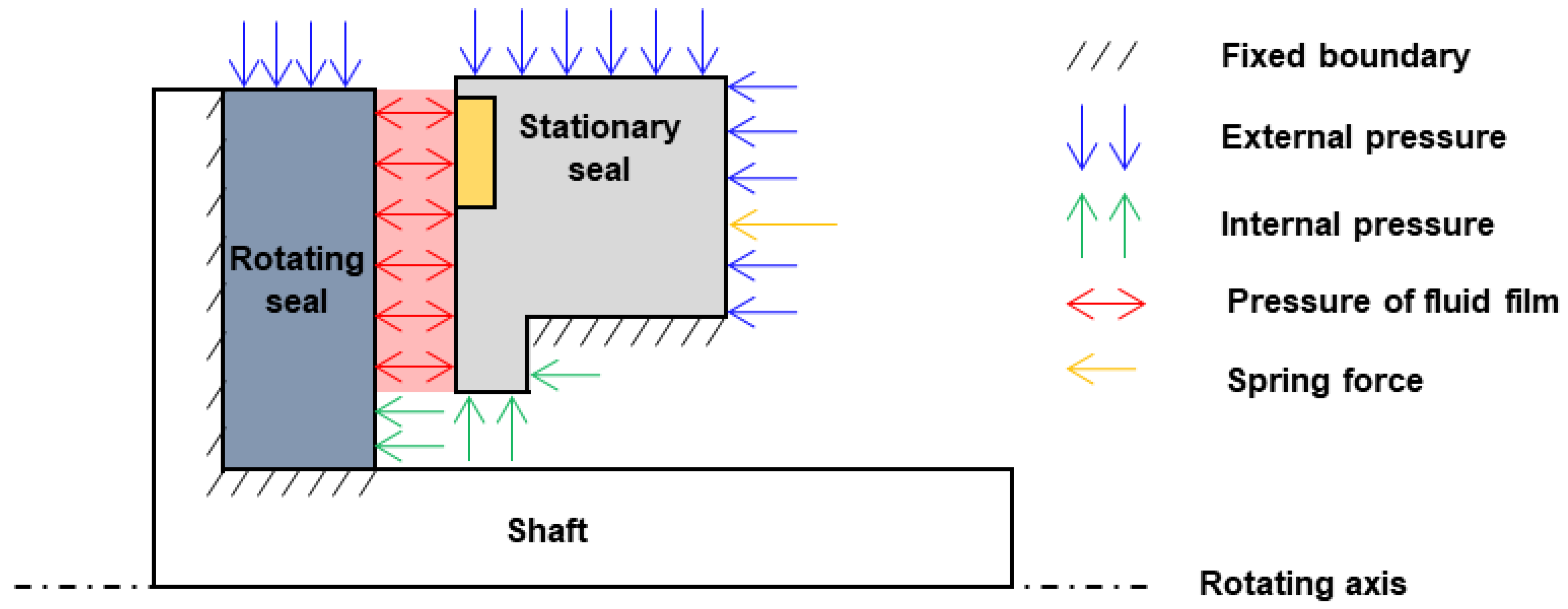
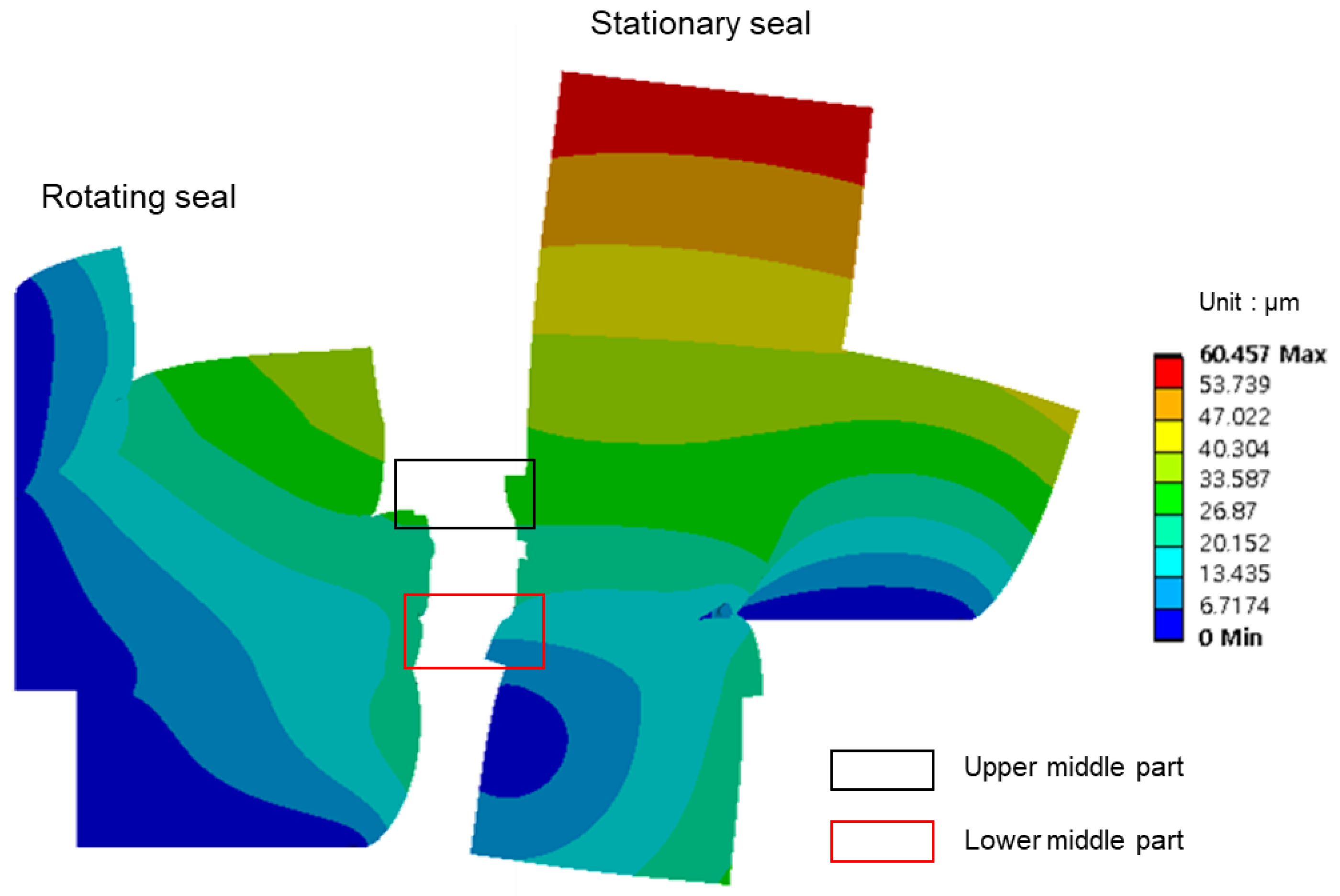
2.3. Heat Conduction and Elastic Deformation of the Seal Structure

The heat conduction equations for the stationary seal and the rotating seal are expressed as Equations (22) and (23), respectively; for the rotating seal, it includes the rotational component in the θ direction.
1 r 2 2 T s θ 2 + r T s r + 2 T s z 2 = 0
k r ρ r C p r 1 r 2 2 T r θ 2 + r T r r + 2 T r z 2 = ω T r θ
Here, Ts, Tr, kr, ρr, and Cpr represent the temperature of the stationary seal, the temperature of the rotating seal, the thermal conductivity of the rotating seal, the density, and the specific heat capacity of the rotating seal, respectively.
Figure 2 illustrates the boundary conditions of the heat conduction equations for the lubricating fluid and the seal structure. An isothermal boundary was applied to the outer radius of the stationary seal, and a convective boundary with air was applied to the inner radius. For the rotating seal, a convective boundary with water coolant was applied to the outer radius, and an isothermal boundary was applied to the inner radius. On the lubrication surface, the heat flux, which is obtained by dividing the generated heat in Equation (13) by the element area, is applied to the lubrication surface. For the other parts, an insulating boundary was applied to calculate the heat transfer between the lubricating fluid and the solid [26,27].
Figure 3 shows the pressure boundary conditions for the analysis of elastic deformation of the seal structure. External pressure was applied to the outer diameter of the stationary seal, and the internal pressure was applied to its inner diameter. Additionally, spring force was applied to the outer diameter of the stationary seal. External pressure was also applied to the outer diameter of the rotating seal, and the internal pressure was applied to its inner diameter. The pressure calculated from the Reynolds equation was applied to the lubricating surface. The other parts were subjected to a fixed boundary condition because they are fixed to the shaft and housing.

2.4. Numerical Algorithm

To calculate the lubrication characteristics at the high temperature and pressure encountered under ELAP operating conditions, it is necessary to consider the variation in the viscosity coefficient according to temperature. The viscosity coefficient depends on temperature and pressure. For liquid, it decreases with increasing temperature until a phase change occurs, after which the viscosity coefficient increases. However, under high pressure (where no phase change occurs), the viscosity coefficient increases with increasing pressure at the same temperature. In this study, Freeprop (available online: https://webbook.nist.gov/chemistry/) was used to determine the viscosity coefficient of each finite element depending on temperature and pressure.
Figure 4 shows the numerical procedure of this study. Lubrication analysis in the fluid film was conducted with a finite element program developed using C++. First, the Reynolds number was calculated on each finite element, and lubrication analysis was conducted based on laminar and turbulent flow. Subsequently, thermal analysis to determine the temperature of the fluid film was conducted using the finite element program developed using C++. In this state, we applied the heat generation obtained from the fluid film analysis to solve the energy equation. An iteration process was required to find the film thickness that satisfies the equilibrium state under the given operating conditions by calculating the opening force based on the initial film thickness (clearance) and comparing it to the closing force. The process was repeated until the force equilibrium state was achieved. The bisection method was used as the iteration method in this study. For this purpose, the minimum and maximum film thicknesses were defined, and the analysis was repeated until the difference between the opening force and the closing force for the calculated film thickness was less than 1 × 10⁻⁴. Then, analyses of heat conduction and elastic deformation of the seal structure were conducted using ANSYS software 2022 R1. In this state, we applied the pressure from the fluid film analysis and the temperature distribution of the heat conduction analysis to solve the elastic deformation of the seal structure. These processes were repeated until the difference in total deformation of all nodes between the previous step and the current step was less than 1 × 10⁻⁴.

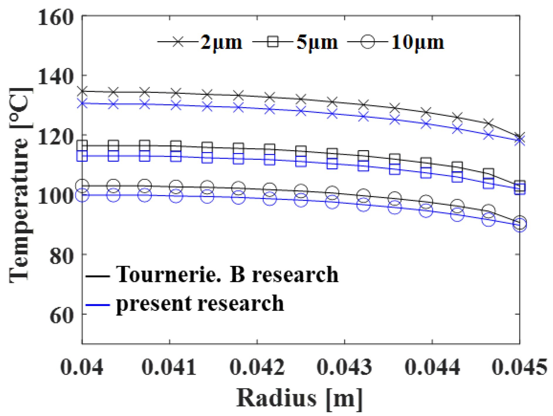
3. Numerical Verification

To validate the developed finite element programs for lubrication and thermal analyses and the proposed numerical procedure, we performed a thermo-fluid coupled analysis of the face seal, as analyzed by Tournerie et al. [28]. The external radius, internal radius, and tapering angle of this face seal were 45 mm, 40 mm, and 0.0001 rad, respectively. The rotating speed, pressure difference, fluid density, initial viscosity, and fluid thermal conductivity were 300 rad/s, 2 MPa, 850 kg/m3, 0.001 Pas, and 0.14 W/mK, respectively. Our finite element model was constructed with 3000 quadrilateral elements. Figure 5 shows a comparison of our temperature distributions along the radial direction with those of Tournerie for film thicknesses of 2, 5, and 10 μm. It shows that our simulated temperature distributions are very close to those of Tournerie, within a discrepancy of 3%. Additionally, our simulated leakage rate for the film thickness of 10 μm is 1.182 × 10⁻⁶ m3/s, very close to Tournerie’s leakage rate of 1.175 × 10⁻⁶ m3/s, with a discrepancy of 0.59%.

4. Results and Discussion
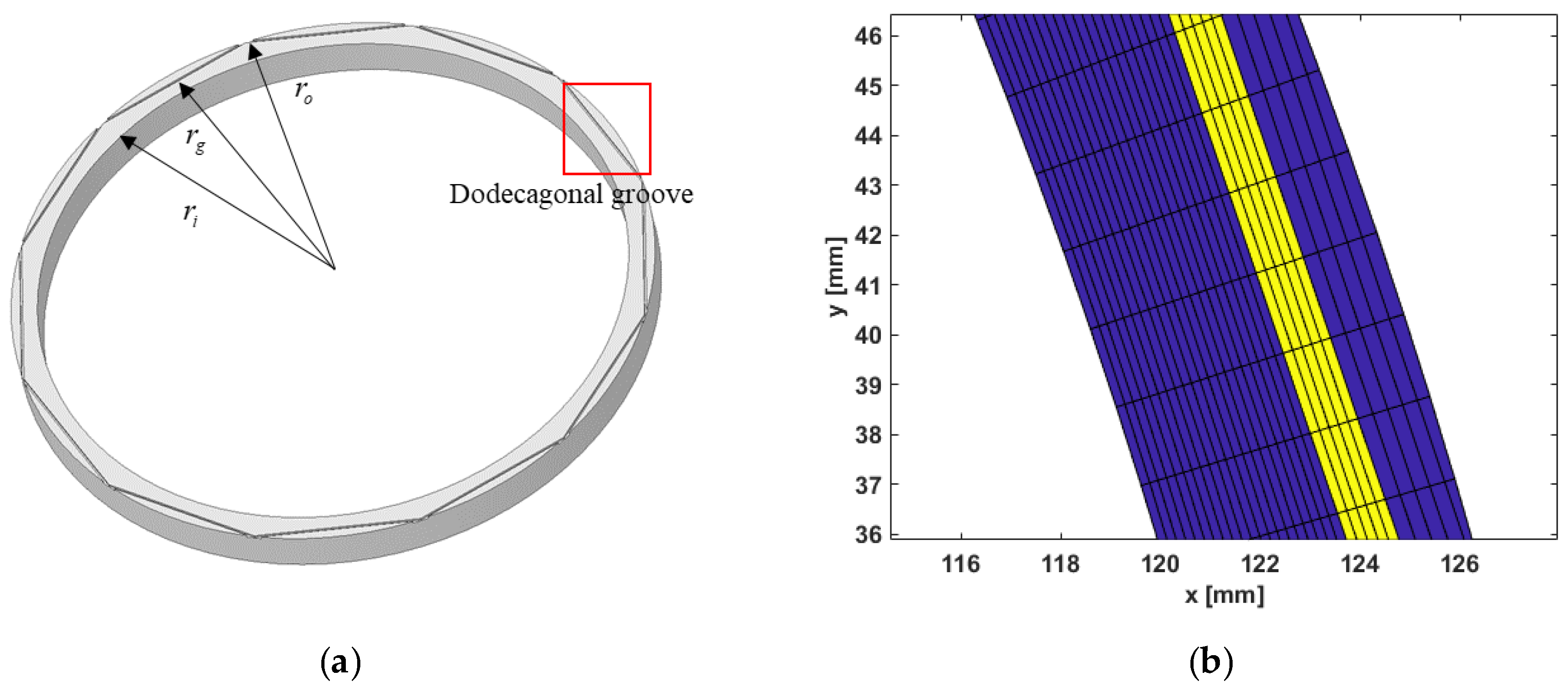
4.1. Analysis Model

We applied the proposed method of the thermo-fluid–structural coupled analysis to investigate the lubrication characteristics of the mechanical seal under normal and ELAP operating conditions. Figure 6a shows the mechanical structure of a mechanical seal with a dodecagonal groove. The finite element model of the mechanical seal was developed with 144,000 quadrilateral elements. Figure 6b is the finite element model corresponding to the boxed area in Figure 6a, and it shows groove and ridge areas. The groove is engraved in the stationary seal, while the rotating seal has a plain shape. Table 1 shows the design variables and operating conditions used for the lubrication analysis of the mechanical seal. Table 2 shows the pressure and temperature boundary conditions of the mechanical seal under normal and ELAP conditions. The pressure differences between normal and ELAP operating conditions were 64 bar and 176 bar, respectively. We assumed that the fluid film in the clearance remained in a liquid state. Figure 7 shows the three-dimensional model to analyze the heat conduction and elastic deformation of the seal structure. In this research, we developed one-quarter of the three-dimensional model and applied a symmetric boundary condition. The gray area is made of silicon carbide, where lubrication occurs, while the rest is carbon graphite. We did not include the shaft and housing in the finite element model in the analysis of elastic deformation and heat conduction because they were much stiffer than that of the carbon graphite and because the thermal conductivity of the shaft and housing was almost equal to that of the carbon graphite, and they were located far from the heat source. Table 3 shows the material properties of the seal structure in the analysis of heat conduction and elastic deformation.

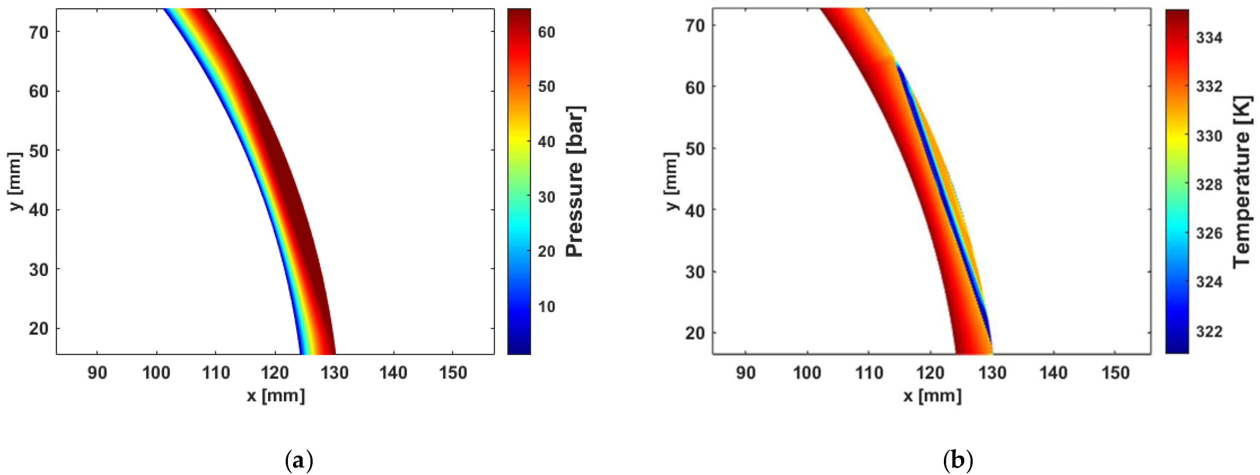
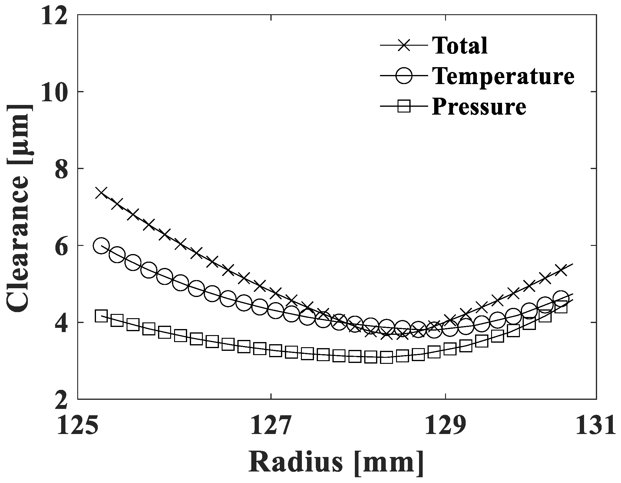
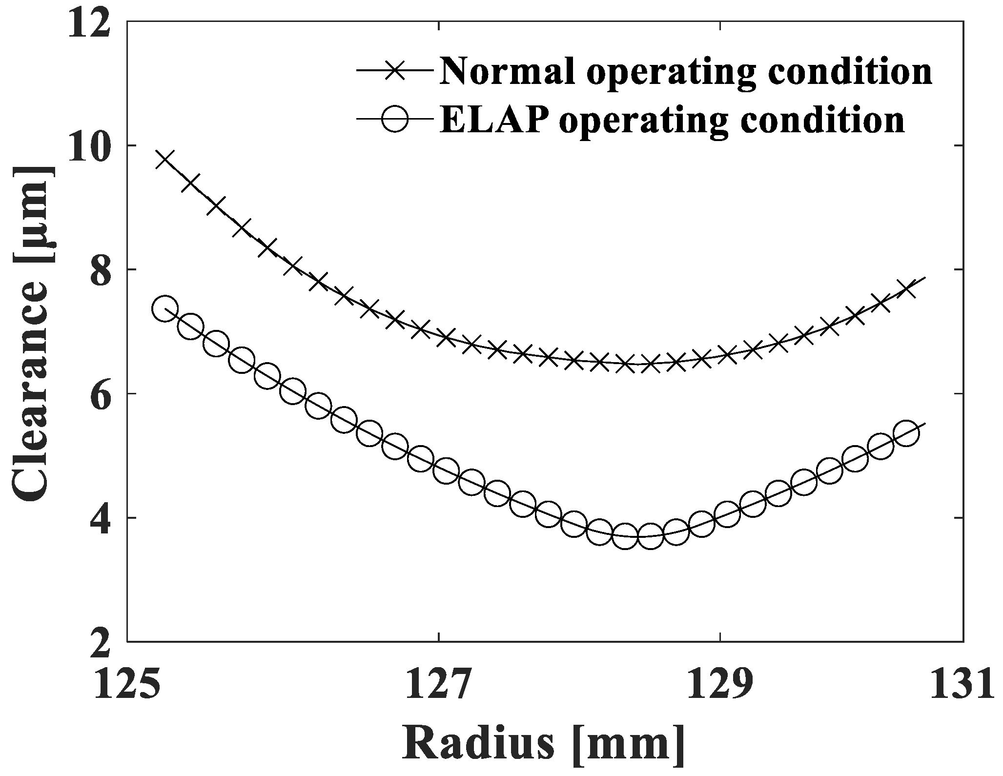
4.2. Characteristics of a Mechanical Seal under Normal Operating Conditions

A thermo-fluid–structural coupled analysis was conducted to analyze the characteristics of a mechanical seal under normal operating conditions. In this normal operating condition, the proposed numerical procedure in Figure 4 was converged after nine iterations, with an average clearance of 7.31 μm. Figure 8 shows the Reynolds number along the radial direction at 0° and 10°. Because there is no groove along the radius at 0°, the Reynolds number is lower than Re = 1000, and no turbulence occurs. However, there is a groove along the radius at 10°, and the Reynolds number is higher than Re = 1000 in the groove area, causing turbulence in the groove area. Figure 9a shows the pressure distribution on the lubrication surface. Under normal operating conditions, the opening force, maximum pressure, and leakage rates were 22,946 N, 64.03 bar, and 8.63 × 10⁻⁵ m3/s, respectively. The maximum pressure is very close to the external pressure because the wedge effect caused by the groove was weak. Figure 9b shows the temperature distribution of the fluid film. The maximum temperature of 335 K occurred at the inner diameter of the seal, and the minimum temperature of 321 K occurred within the groove due to the lubricating fluid within the groove depth.
Figure 10 shows the temperature distribution of the seal structure due to heat conduction. The maximum temperature of 335.4 K occurs at the middle lower part of the stationary seal, where a relatively high temperature is observed due to the low convective heat transfer coefficient of air. At the middle upper part of the rotating seal, a relatively low temperature is observed due to the high convective heat transfer coefficient of water. Figure 11 shows the elastic deformation of the mechanical seal under normal operating conditions. The maximum deformation of 4.5 μm occurs at the top of the stationary seal because the pressure of 64 bar at the outer diameter of both the stationary and rotating seals is much greater than the pressure of 1 bar at the inner diameter. Figure 12 shows the clearance along the radial direction due to temperature, pressure, and their interaction. When pressure is only applied, the clearance changes from a maximum of 4.92 μm at the outer radius to a minimum of 3.46 μm near the middle, and the clearance at the outer radius is slightly greater than that at the inner radius because of high external pressure. When the temperature is applied, the clearance changes from a maximum of 7.48 μm at the inner radius to a minimum of 4.7 μm near the middle, and the clearance at the inner radius is greater than that at the outer radius because of the high inner temperature. Temperature changes the clearance more significantly than pressure. When both pressure and temperature are applied, clearance changes from the maximum of 9.77 μm at the inner radius to the minimum of 6.47 μm near the middle, and the clearance at the inner radius is greater than that at the outer radius, mostly due to high inner temperature.

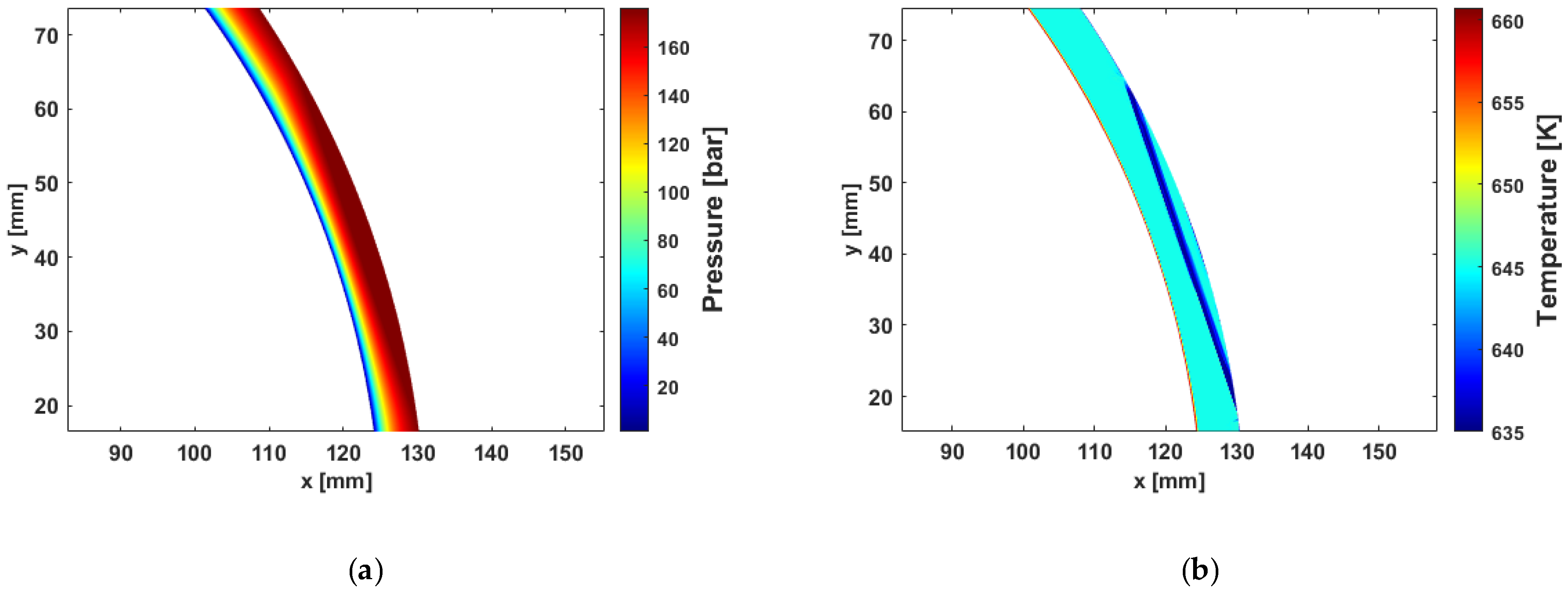
4.3. Characteristics of a Mechanical Seal under ELAP Operating Conditions

The characteristics of a mechanical seal under ELAP operating conditions were analyzed by using the proposed thermo-fluid–structural coupled analysis. As shown in Figure 4, the proposed numerical procedure was converged to an average clearance of 4.91 μm after 23 iterations. Because the groove depth affects the Reynolds number more significantly than clearance change, turbulence occurs only at the groove area in the ELAP operating condition. Figure 13a shows the pressure distribution on the lubrication surface, and it shows that the maximum pressure is very close to the external pressure because the wedge effect caused by the groove is weak. Under ELAP operating conditions, the opening force, maximum pressure, and leakage rate are 61,564 N, 176 bar, and 9.7 × 10⁻⁵ m3/s, respectively. Figure 13b shows the temperature distribution of the fluid film. The maximum temperature of 660 K occurs at the inner diameter of the seal, and the minimum temperature of 635 K occurs within the groove due to the lubricating fluid within the groove depth. According to the NIST, the coolant (water) remains in a liquid state up to 628.29 K at 176 bar and up to 372.76 K at 1 bar. Vaporization of the fluid film may occur where the temperature of the fluid film rises over the boiling temperature of water, as shown in Figure 13. Figure 14 shows the temperature distribution of the seal structure due to heat conduction. The maximum temperature of 669.3 K occurs at the middle lower part of the stationary seal with the distribution of a relatively high temperature due to a low convective heat transfer coefficient of air. A relatively low temperature occurred at the middle upper part of the rotating seal due to the high convective heat transfer coefficient of water.
Figure 15 shows the elastic deformation of the mechanical seal under ELAP operating conditions, and the deformed shape of the mechanical seal under ELAP operating conditions is very similar to that under normal operating conditions. However, the maximum deformation of 60.5 μm occurs at the top of the stationary seal because the high pressure of 176 bar at the outer diameter of both the stationary and rotating seals is much greater than the pressure of 1 bar at the inner diameter. Figure 16 shows the clearance along the radial direction due to temperature, pressure, and their interaction, respectively. The maximum clearances due to pressure, temperature, and their interaction are 4.59 μm at the outer radius, 5.99 μm at the inner radius, and 7.37 μm at the inner radius. The minimum clearances due to pressure, temperature, and their interaction are 3.09 μm, 3.8 μm, and 3.69 μm near the middle, and it shows that the pressure additionally decreases the minimum clearance near the middle when both temperature and pressure are considered. In total, elastic deformation of the seal structure happens near clearance, and the temperature has a more significant influence than pressure in ELAP operating conditions. Figure 17 shows the clearance of the fluid film along the radial direction under normal and ELAP operating conditions, and it shows that the clearance due to high temperature and pressure under ELAP operating conditions is much smaller than that under normal operating conditions. However, the leakage rate under ELAP operating conditions (9.7 × 10⁻⁵ m3/s) slightly increased in comparison to that under normal operating conditions (8.63 × 10⁻⁵ m3/s) due to the high internal pressure.

5. Conclusions

In this paper, we proposed a thermo-fluid–structural coupled analysis method to predict the pressure and temperature distributions, the change in the fluid film clearance due to elastic deformation of the mechanical seal, and the resulting leakage rate under normal and ELAP operating conditions of the RCP. We developed a finite element program for the general Reynolds equation, including the turbulence effect to calculate the pressure, opening force, and leakage rate of fluid lubricant and the two-dimensional energy equation to calculate the temperature distribution of the fluid lubricant. The accuracy of the developed program was verified by comparing the simulated temperature distribution and leakage rate with those of previous research. Heat conduction and elastic deformation due to pressure and temperature changes at the seal structure were analyzed using the ANSYS program. The results show that temperature more significantly affects the elastic deformation of the seal structure near clearance compared to pressure under both normal and ELAP operating conditions. High temperature and pressure of the coolant under ELAP operating conditions deformed the seal structure and resulted in a much smaller clearance of the fluid film than in normal operating conditions. Even in the small clearance of ELAP operating conditions, the leakage rate increased due to high internal pressure and low viscosity. A high temperature of the coolant in the seal structure under ELAP operating conditions rises over the boiling temperature of the coolant, which may cause the vaporization of the coolant. The effect of two-phase flow in the fluid film under ELAP operating conditions will be a future research topic to accurately analyze the fluid film and the thermo-fluid–structural coupled analysis of the seal structure under ELAP operating conditions. This research will contribute to the development of robust mechanical seals for RCP by accurately predicting the characteristics of mechanical seals, especially under ELAP in the RCP.

Author Contributions

Conceptualization, G.J.; methodology, Y.P. and G.H.; software, Y.P. and G.H.; validation, Y.P.; formal analysis, T.K. and G.H.; investigation, Y.P. and M.K.; resources, M.K. and T.K.; data curation, J.C. and S.J.; writing—original draft preparation, Y.P. and G.H.; writing—review and editing, G.J.; visualization, Y.P. and G.H.; supervision, G.J.; project administration, G.J.; funding acquisition, G.J. All authors have read and agreed to the published version of the manuscript.

Funding

This work was supported by Korea Energy Technology Evaluation and Planning (KETEP) grant funded by the Ministry of Trade, Industry, and Energy (MOTIE) (20222B10100010, Development of silicon carbide composite material technology with improved surface lubricity, 2023). This work was supported by Korea Research Institute for Defense Technology planning and advancement (KRIT) grant funded by Defense Acquisition Program Administration (DAPA) (No. KRIT-CT-21-008, Predicting precise leakage rates of carbon seals and technology of designing aerodynamic patterns for improving lifetime, 2023).

Data Availability Statement

Data are contained within the article.

Conflicts of Interest

Authors Sanghyun Jun, Jeongmook Choi, Taegyu Kim and Minsoo Kang were employed by the company Department of Engineering, Flowserve KSM. The remaining authors declare that the research was conducted in the absence of any commercial or financial relationships that could be construed as a potential conflict of interest.

Nomenclature

DnTotal elastic deformation of all nodes at the n-th iteration
FcloseClosing force [N]
FopenOpening force [N]
GrFluid state coefficients for radial flow
GθFluid state coefficient for circumferential flow
hFilm thickness [mm]
hcMinimum film thickness [mm]
hgGroove depth [mm]
hdDeformation amount [mm]
pPressure of fluid film [bar]
T Temperature of fluid film [K]
U Fluid velocity [m/s]
w Weighting function
μ Viscosity [Pa∙s]
ρ Density [kg/m3]
η Arbitrary vector
N Shape function vector
P e Element pressure vector [bar]
T e Element temperature vector [K]
ΩInterested domain
ω Rotating velocity [rad/s]
ReReynolds number
PrPrandtl number
NuNusselt number

References

  1. Yang, J.H.; Wang, J.R.; Shih, C.; Huang, C.F.; Chen, S.W. The simulation and study of ELAP event with URG and FLEX mitigation strategies for PWR by using TRACE code. Kerntechnik 2019, 84, 72–83. [Google Scholar] [CrossRef]
  2. Thomas, S.; Brunetiere, N.; Tournerie, B. Numerical modeling of high pressure gas face seals. J. Tribol. 2006, 128, 396–405. [Google Scholar] [CrossRef]
  3. Thomas, S.; Brunetiere, N.; Tournerie, B. Thermoelastohydrodynamic behavior of mechanical gas face seals operating at high pressure. J. Tribol. 2007, 129, 841–850. [Google Scholar] [CrossRef]
  4. Brunetiere, N.; Thomas, S.; Tournerie, B. The parameters influencing high-pressure mechanical gas face seal behavior in static operation. Tribol. Trans. 2009, 52, 643–654. [Google Scholar] [CrossRef]
  5. Nyemeck, A.P.; Brunetiere, N.; Tournerie, B. A mixed thermoelastohydrodynamic lubrication analysis of mechanical face seals by a multiscale approach. Tribol. Trans. 2015, 58, 836–848. [Google Scholar] [CrossRef]
  6. Mosavat, M.; Moradi, R.; Takami, M.R.; Gerdroodbary, M.B.; Ganji, D.D. Heat transfer study of mechanical face seal and fin by analytical method. Eng. Sci. Technol. Int. J. 2018, 21, 380–388. [Google Scholar] [CrossRef]
  7. Su, H.; Rahmani, R.; Rahnejat, H. Thermohydrodynamics of bidirectional groove dry gas seals with slip flow. Int. J. Therm. Sci. 2016, 110, 270–284. [Google Scholar] [CrossRef]
  8. Su, W.; Liu, W.; Yan, L.; Zhang, Y. Thermal performances of the wave-tilt-dam seal in a reactor coolant pump for sustainable development. Sustain. Energy Technol. Assess. 2022, 52, 102042. [Google Scholar] [CrossRef]
  9. Brunetiere, N.; Tournerie, B.; Frene, J. TEHD lubrication of mechanical face seals in stable tracking mode: Part 1—Numerical model and experiments. J. Tribol. 2003, 125, 608–616. [Google Scholar] [CrossRef]
  10. Brunetiere, N.; Tournerie, B.; Frene, J. TEHD lubrication of mechanical face seals in stable tracking mode: Part 2—Parametric study. J. Tribol. 2003, 125, 617–627. [Google Scholar] [CrossRef]
  11. Brunetiere, N.; Rouillon, M. Fluid flow regime transition in water lubricated spiral grooved face seals. Tribol. Int. 2021, 153, 106605. [Google Scholar] [CrossRef]
  12. Mo, H.; Hu, Y.; Quan, S. Thermo-hydrodynamic lubrication analysis of slipper pair considering wear profile. Lubricants 2023, 11, 190. [Google Scholar] [CrossRef]
  13. Grun, H.; Feldmeth, S.; Bauer, F. Multiphase computational fluid dynamics of rotary shaft seals. Lubricants 2022, 10, 347. [Google Scholar] [CrossRef]
  14. Liu, Y.; Liu, W.; Li, Y.; Liu, X.; Wang, Y. Mechanism of a wavy-tilt-dam mechanical seal under different working conditions. Tribol. Int. 2015, 90, 43–54. [Google Scholar] [CrossRef]
  15. Galenne, E.; Pierre, D.I. Thermo-elasto-hydro-dynamic modeling of hydrostatic seals in reactor coolant pumps. Tribol. Trans. 2007, 50, 466–476. [Google Scholar] [CrossRef]
  16. Su, W.T.; Wang, Y.H.; Feng, X.D.; Li, X.B. Thermal-liquid–solid coupling characteristics of wavy-end-face mechanical seal for reactor coolant pump. Nucl. Eng. Des. 2023, 414, 112545. [Google Scholar] [CrossRef]
  17. Wang, J.L.; Chen, X.Y.; Binama, M.; Su, W.T.; Wu, J. A numerical study on mechanical seal dynamic characteristics within a reactor coolant pump. Front. Energy Res. 2022, 10, 879198. [Google Scholar] [CrossRef]
  18. Srivastava, G.; Chiappa, P.; Shelton, J.; Higgs, C.F. A thermo-elasto-hydrodynamic lubrication modeling approach to the operation of reactor coolant pump seals. Tribol. Int. 2019, 138, 487–498. [Google Scholar] [CrossRef]
  19. Meng, X.; Qiu, Y.; Ma, Y.; Peng, X. An investigation into the thermo-elasto-hydrodynamic effect of notched mechanical seals. Nucl. Eng. Technol. 2022, 54, 2173–2187. [Google Scholar] [CrossRef]
  20. Huang, W.; Liao, C.; Liu, X.; Suo, S.; Liu, Y.; Wang, Y. Thermal fluid-solid interaction model and experimental validation for hydrostatic mechanical face seals. Chin. J. Mech. Eng. 2014, 27, 949–957. [Google Scholar] [CrossRef]
  21. Hirs, G.G. A bulk-flow theory for turbulence in lubricant films. J. Lubr. Technol. 1973, 95, 137–145. [Google Scholar] [CrossRef]
  22. Hirs, G.G. A systematic study of turbulent film flow. J. Tribol. 1974, 96, 118–126. [Google Scholar] [CrossRef]
  23. Ma, C.; Bai, S.; Peng, X. Thermo-hydrodynamic characteristics of spiral groove gas face seals operating at low pressure. Tribol. Int. 2016, 95, 44–54. [Google Scholar] [CrossRef]
  24. Yu, B.; Hao, M.; Xinhui, S.; Wang, Z.; Fuyu, L.; Yongan, L. Analysis of dynamic characteristics of spiral groove liquid film seal under thermal–fluid–solid coupling. Ind. Lubr. Tribol. 2021, 73, 882–890. [Google Scholar] [CrossRef]
  25. Becker, K.M. Measurements of convective heat transfer from a horizontal cylinder rotating in a tank of water. Int. J. Heat Mass Transf. 1963, 6, 1053–1062. [Google Scholar] [CrossRef]
  26. Wu, D.; Jiang, X.; Yang, S.; Wang, L. Three-dimensional coupling analysis of flow and thermal performance of a mechanical seal. J. Therm. Sci. Eng. Appl. 2014, 6, 196–204. [Google Scholar] [CrossRef]
  27. Parviz, M.; Nori, A.O.; Robert, L.P.; Larry, E.J. Experimental and computational investigation of flow and thermal behavior of a mechanical seal. Tribol. Trans. 1999, 42, 731–738. [Google Scholar]
  28. Tournerie, B.; Danos, J.C.; Frene, J. Three-dimensional modeling of THD lubrication in face seals. J. Tribol. 2000, 123, 196–204. [Google Scholar] [CrossRef]
Figure 1. (a) Structure of a mechanical seal in an RCP and (b) a magnified drawing of the mechanical seal in the dotted box of (a).
Lubricants 12 00212 g001
Figure 2. Heat transfer boundaries of a mechanical seal.
Lubricants 12 00212 g002
Figure 3. Pressure boundaries of a mechanical seal.
Lubricants 12 00212 g003
Figure 4. Numerical procedure of thermo-fluid–structural coupled analysis of a mechanical seal.
Lubricants 12 00212 g004
Figure 5. Temperature distribution according to film thickness.
Lubricants 12 00212 g005
Figure 6. 3D Geometry (a) and FE model (b) of a mechanical seal for RCP for lubrication and thermal analyses.
Lubricants 12 00212 g006
Figure 7. 3D Geometry of a mechanical seal for structural elastic deformation analysis.
Lubricants 12 00212 g007
Figure 8. Reynolds number of the fluid film at θ = 0° and θ = 10° under normal operating conditions.
Lubricants 12 00212 g008
Figure 9. Pressure (a) and temperature distributions (b) in the fluid film of the mechanical seal under normal conditions.
Lubricants 12 00212 g009
Figure 10. Temperature distribution of the mechanical seal under normal operating conditions.
Lubricants 12 00212 g010
Figure 11. Elastic deformation of the mechanical seal under normal operating conditions.
Lubricants 12 00212 g011
Figure 12. Clearance along the radial direction due to temperature, pressure, and their interaction under normal operating conditions.
Lubricants 12 00212 g012
Figure 13. Pressure (a) and temperature distributions (b) in the fluid film of the mechanical seal under ELAP operating conditions.
Lubricants 12 00212 g013
Figure 14. Temperature distribution of the mechanical seal under ELAP operating conditions.
Lubricants 12 00212 g014
Figure 15. Elastic deformation of the mechanical seal under ELAP operating conditions.
Lubricants 12 00212 g015
Figure 16. Clearance along the radial direction due to temperature, pressure, and their interaction under ELAP operating conditions.
Lubricants 12 00212 g016
Figure 17. Clearance of the fluid film along radial direction under normal and ELAP operating conditions.
Lubricants 12 00212 g017
Table 1. Design variables and operating conditions of the mechanical seal.
ParameterValue
Outer radius, ro [mm]131
Groove radius, rg [mm]128.7
Inner radius, ri [mm]125
Balance radius, rb [mm]127
Radial groove length [mm]1
Number of grooves [ea]12
Groove depth [mm]1
Fluid specific heat capacity, Cp [J/kgK]4184
Fluid thermal conductivity, k [W/mK]0.592
Rotating   speed ,   ω [rpm]1200
Table 2. Pressure and temperature boundary conditions of the mechanical seal under normal and ELAP operating conditions.
ParameterNormal ConditionELAP Condition
External pressure, po [bar]64176
Internal pressure, pi [bar]11
Seal fluid temperature, To [K]313583
Ambient temperature, Ti [K]313583
Fluid density, ρ [kg/m3]995.02709.76
Fluid viscosity, μ [μPas]655.3885.44
Table 3. Material properties of the seal structure in the analysis of the heat conduction and elastic deformation of the seal structure.
ParameterCarbon GraphiteSilicon Carbide
Density, ρr [kg/m3]18003100
Young’s modulus [GPa]25400
Poisson’s coefficient0.20.17
Specific heat capacity, Cpr [J/kgK]710400
Thermal conductivity, kr [W/mK]15150
Linear thermal expansion coefficient [/10−6 °C]44.3
Disclaimer/Publisher’s Note: The statements, opinions and data contained in all publications are solely those of the individual author(s) and contributor(s) and not of MDPI and/or the editor(s). MDPI and/or the editor(s) disclaim responsibility for any injury to people or property resulting from any ideas, methods, instructions or products referred to in the content.

