Abstract
In vertical shaft pump turbines operating in pumped storage power plants an important role is played by a thrust bearing. Due to the bidirectional character of operation, thrust bearing tilting pads have to be supported symmetrically, which is known to be unfavourable from the point of view of their performance. Large thrust bearings have to be carefully designed so as to minimise excessive thermo-elastic pad deformations. The research into fluid film thrust bearings has been quite extensive over the years, comprising theoretical studies of bearing properties with the use of more and more sophisticated calculation codes. On the other hand, the availability of experimental field data on bearing operation is limited, for obvious reasons. In this paper the authors present part of the results of extensive field tests of a large bearing of a pump-turbine they have conducted in a pumped storage power plant. Hopefully this data will be of interest to other researchers to compare theoretical predictions to measurement data.
1. Introduction
Pumped storage power plants play an important role in contemporary power systems producing electricity during peaks of demand and utilizing a surplus of energy production in low-demand periods for storing energy in water reservoirs. Their use is important nowadays in cooperation with wind power farms. The most typical units in pumped storage power plants are vertical shaft Francis-type pump-turbines. A characteristic feature of these setups is bidirectional operation, with one direction of rotation in generating mode and the opposite direction in pumping mode when the unit is powered by electricity from the grid, pumping water to the upper reservoir. Pumped storage power plants are usually built as large objects and the machines installed typically exceed a power of 100 MW.
In vertical shaft machines an important role is played by a thrust bearing, which accommodates vertical forces of the weight of the rotating parts, as well as hydraulic forces acting on a turbine runner. The fluid film thrust bearings in these machines are, in most cases, of the tilting pad type. Operation of such bearings is bidirectional, so the bearing pads have to be supported symmetrically, which is unfavourable for their performance according to the literature results [1,2], yet their specific load is quite high for the sake of minimising power losses. On the other hand, it is an established fact that, because of the scale effect of thermoelastic deformations in thrust bearings [3], the large diameter bearings must be designed in a way that minimises pad deformations. Therefore, the large thrust bearings of pumped storage power plants should be considered critical machine components, with special care in the design and operation. The special care in design and operation is also reflected by numerous publications over the years, comprising demonstrations of achievements of particular bearing design modifications, such as double layer bearing, described and tested in [4]. Detailed theoretical calculations of bearing properties were presented with the use of more and more sophisticated models including heat exchange between the pads and at the pads’ surroundings, like the code Marmac1, described in [5]. An important modification of the bearings contributing to minimized thermal deformations were also the bearings with a polymer lining of the pad surface studied in numerous publications, e.g., [6]. Additionally, a common design feature of hydrostatic jacking, meant to improve bearing operation in transient states, was an object of research and the results were, for example, discussed in [7]. The codes used for bearing calculations are quite sophisticated, seeming to take into account all effects significant for bearing performance, such as deformations, lubricant properties as a function of temperature and pressure, oil mixing between the pads, heat exchange, etc. [8,9,10]. However, the accuracy of these codes is not clear, as there are few papers comparing theoretical and experimental results for large bearings. These examples are the results of the testing of a large bearing in a special unique test rig reported by Yuan et al. [11]. Other published results of comparisons between calculations and field data were presented by Dąbrowski and Wasilczuk [12], where the object was a hydrogenerator bearing with a system of compensation of thermal deflections; by Wodtke et al. [13], where the results of one of the largest thrust bearings in the world, installed in the Itaipu power plant were presented, and the method utilized was FSI (fluid structure interaction) combining a CFD (computational fluid dynamics) solution for a fluid film with a FEM (finite element method) solution for a solid structure. Huang et al. [14] published a detailed comparison between the experimental results obtained in a special test rig on a bidirectional bearing and numerical predictions. The comparison showed quite good overall agreement on the oil film thickness, pressure, and temperature. The calculation method was a combination of FDM (finite difference method) and FEM.uang Th A relative shortage of direct comparisons between calculations and field data of large thrust bearings is quite understandable, bearing in mind the difficulty in gathering detailed test results for large bearings. Due to many operational problems in pump turbines of one Polish power plant, an extensive program of field tests on thrust bearings has been carried out, aimed at improving bearing reliability [15,16]. Data presented in this paper comprises standard hydrodynamic operation and a special hybrid regime. The hybrid regime, when the hydrostatic system was activated during steady state operation, was only used for testing. The data enables one to see trends of changes of various parameters, and compare the hybrid and hydrodynamic regimes. They can also be used by other researchers for comparing their theoretical predictions to measurement data.
2. Object of the Research
2.1. Thrust Bearing of a 125 MW Pump Turbine
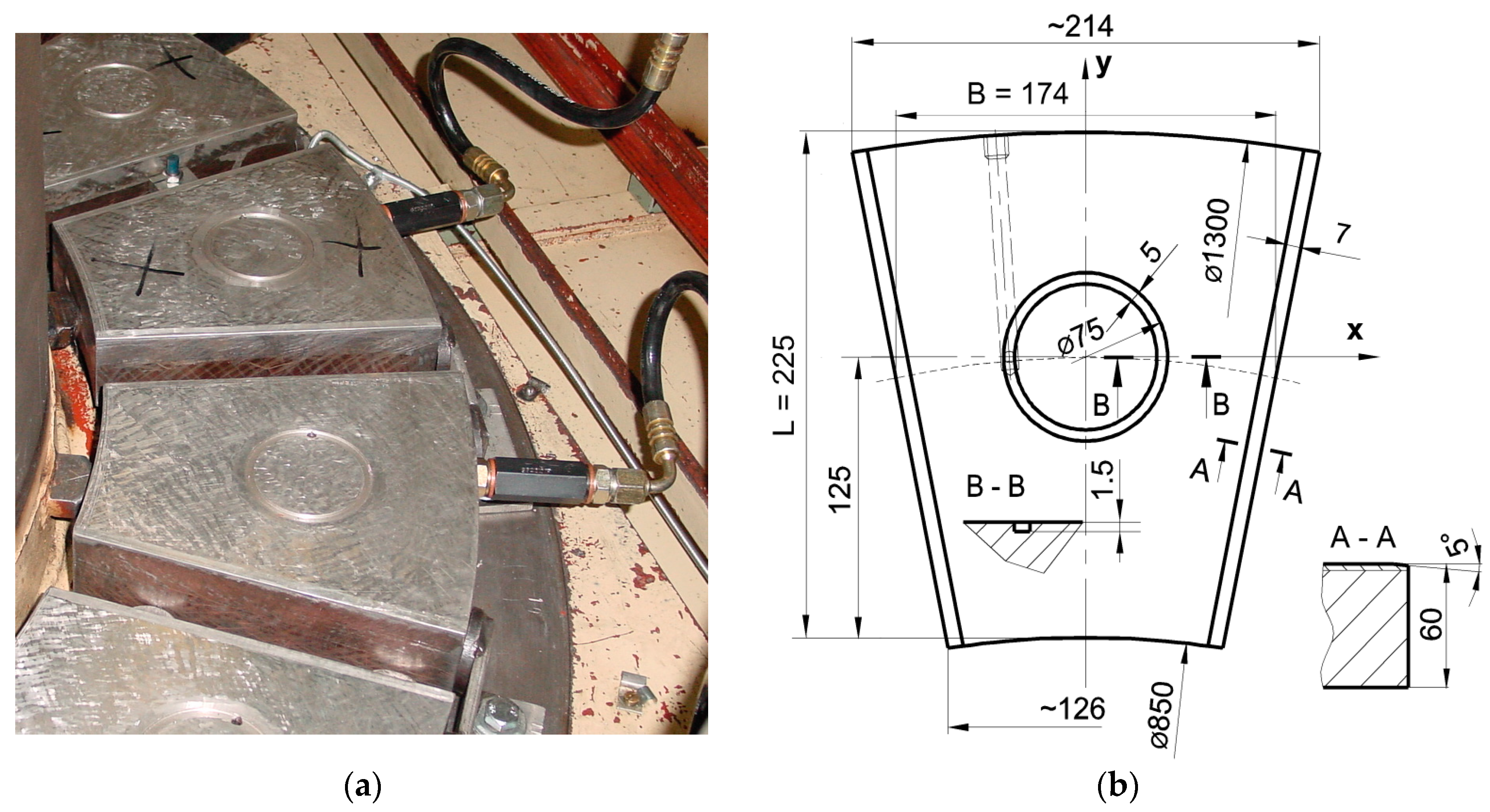
Thrust bearings of the tested machines are tilting pad bearings with pads supported on a “spring mattress”. The thrust bearing is installed above the generator together with an upper radial bearing (also of the tilting pad type). The photograph of the bearing during repair works is shown in Figure 1a—one may notice hydrostatic pockets machined in the pads’ faces and hoses and non-return valves for delivery of the high-pressure oil to the pads during start-ups and stops—which is a very common feature of operation of large thrust bearings.
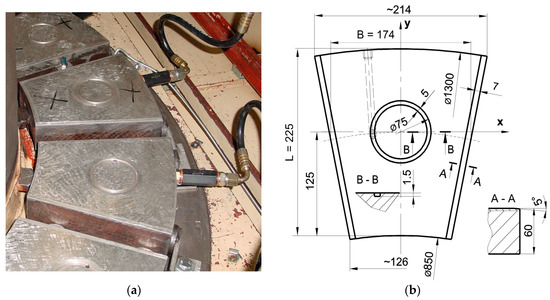
Figure 1.
Spring-supported thrust bearing, (a) photo of the bearing; and (b) dimensions of the bearing pad.
Basic specifications of the thrust bearing are listed in Table 1. Bearing pad dimensions are shown in Figure 1b. The pad is made of mild steel and lined with a high-tin bearing alloy, the sliding surface roughness is Ra 0.2 µm, and the tolerance of planarity is 0.01 mm.

Table 1.
Specifications of the pump turbine and the thrust bearing.
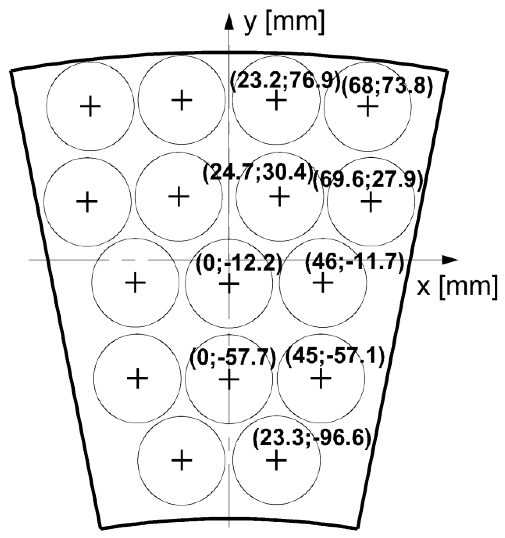
Each pad is supported on 16 springs, and Figure 2 shows the distribution of the springs. The spring constant of the springs is not accurately known—according to various data—including measurements, calculations, and original drawings it varies from 4200 N/mm to 4900 N/mm. A hydrostatic jacking system is used to improve the bearing performance in transient states. High-pressure oil is pumped to the pockets in the pad (see Figure 1). The high-pressure gear pump delivers oil through the maximum valve (set at 13 MPa) and a high-pressure fine filter to the manifold and from the manifold through elastic hoses, non-return valves, and orifices to each pad. The system is activated at the beginning of the start-up and switched off when the rotational speed reaches 85% of the normal speed. During stopping, the system is activated when the rotational speed falls below 85% of the normal speed. Specifications of the high pressure system are as follows:

Figure 2.
Distribution of the springs supporting the pad.
- ◾
- High pressure pump—gear pump, Q = 25 L/min at 1500 rpm
- ◾
- Maximum valve setting, p = 13 MPa
- ◾
- Orifice in each pad—jet of ∅ 0.75 mm and length 3 mm.
2.2. Bearing Instrumentation
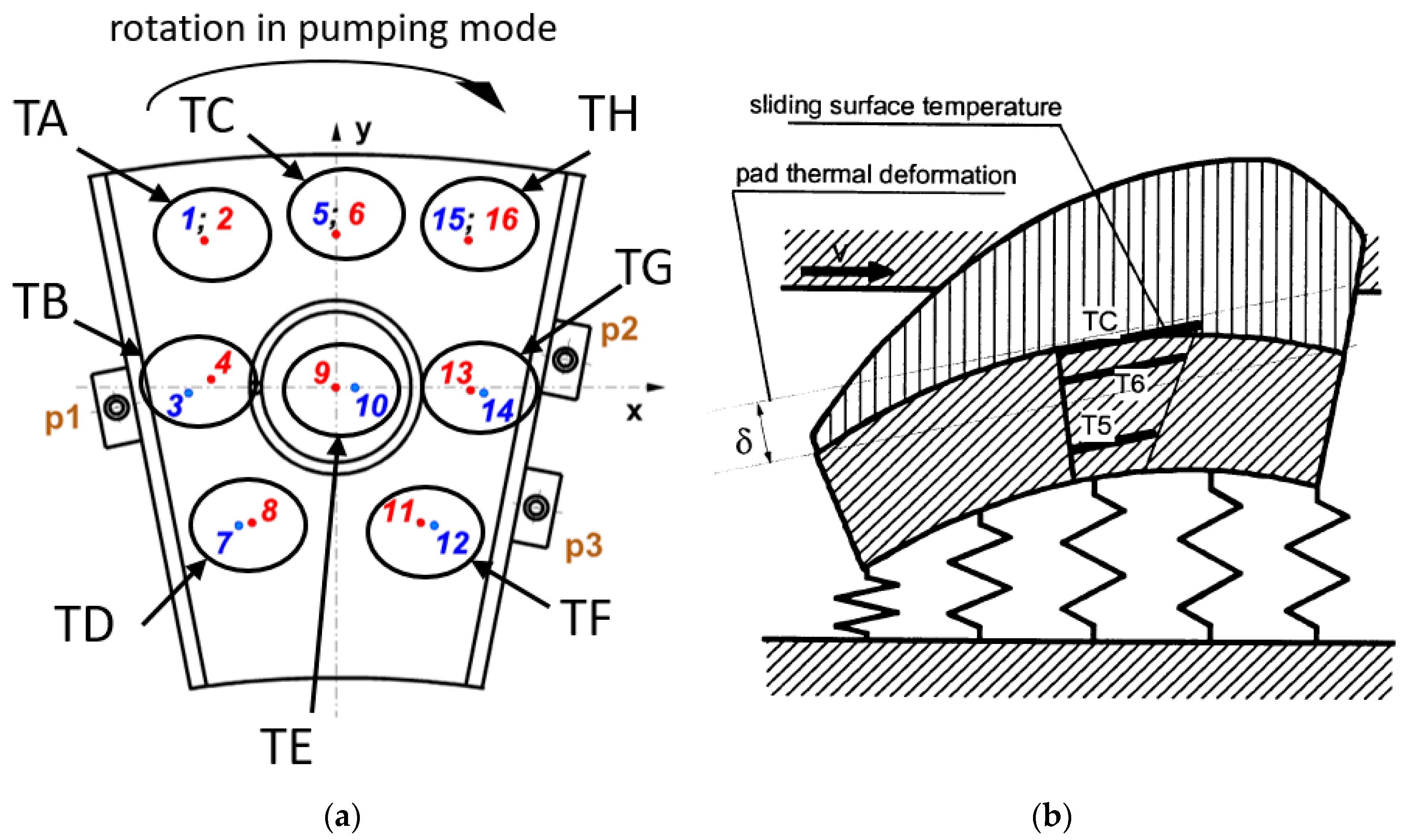
A special instrumented pad was installed in each of the two tested machines. Instrumentation built into the bearing pads was composed of 16 thermocouples and three eddy-current proximity probes. Thermocouples were arranged in pairs (1 and 2; 3 and 4; 7 and 8; etc.). One thermocouple of each pair was situated in the vicinity of the sliding surface, just below the Babbitt layer and the other near the bottom of the pad, 5 or 6 mm from the pad back. Copper-Constantan thermocouples (Type T, Cu-CuNi) of 2 mm diameter were used. Thermocouples in a PTFE liner were installed in 2 mm holes drilled in the bearing pad. No special calibration of the thermocouples was carried out and the temperature was evaluated with the use of the standard coefficient for T-type thermocouples provided by their manufacturer. According to thermocouples manufacturer’s specification possible error of temperature measurement is 0.5 °C. On the basis of measured temperatures the temperature at the surface was evaluated with the use of linear extrapolation—for example, TA was calculated on the basis of T1 and T2 (see Figure 3). Three proximity probes (p1, p2, p3) were fixed to the sides of the pad with the intention of measuring the pad position with respect to the collar. Their distribution is shown in Figure 3 and the coordinates are shown in Table 2 and Table 3.
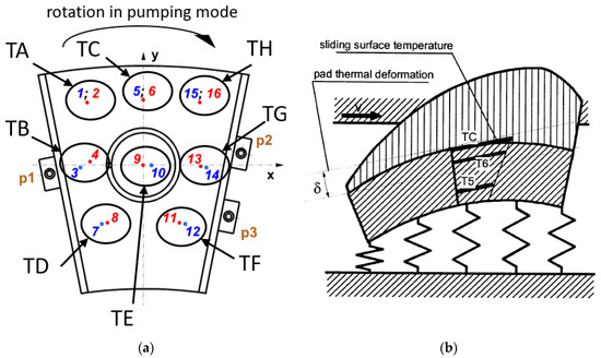
Figure 3.
(a) Distribution of the thermocouples (1–16) and proximity probes (p1–p3) in the instrumentation pad (thermocouples marked with red are situated close to the sliding surface, and those marked with blue are close to the pad back), TA-TH designation of surface temperature; and (b) thermal deformation of the pad and illustration of the evaluation of surface temperature on the basis of the linear extrapolation of the measurement results.
Table 2.
Coordinates of the thermocouples (see Figure 3).
Table 3.
Coordinates of the proximity probes p1–p3 (see Figure 8).
Most of the results presented in this paper, however, were acquired in Unit 2. Unfortunately, the proximity probes did not give reliable results, so in further parts of the paper the film thickness results are shown for the same operating conditions, but from earlier measurements in Unit 1—nominally the same, with the same bearing geometry. The axial load is similar, but not identical, due to some design details. More data from measurements in Unit 1, where proximity probes operated reliably, can be found in [16] together with the details of data processing, especially how temperature effects were taken into account, as well as how zero film thickness was evaluated.
During the research the condition monitoring system of the power plant was used in parallel to the instrumentation pad. The condition monitoring system was used to measure standard quantities determining thrust bearing operating conditions, such as machine output, rotational speed, hydrostatic pump pressure, shaft axial displacements (proportional to bearing axial load changes), and oil bath temperature. Basically, data was recorded at 2 s intervals apart from steady state operation when the interval was 30 s.
3. Results and Discussion
3.1. Temperature Distribution in Various Modes of Operation
Field tests were carried out for all most important machine operating regimes both in steady state and during start-up and stopping. Here, because of consistency requirements, two basic regimes of steady state operation were selected: pumping mode and turbine. Pump and turbine operation differ in the direction of rotation and also slightly in the axial load of the bearing, due to different hydraulic forces acting on the runner. Each of these two regimes was tested in two modes: usual hydrodynamic operation of the thrust bearing and hybrid mode of operation in which the hydrostatic jacking pump was switched on in the steady state.
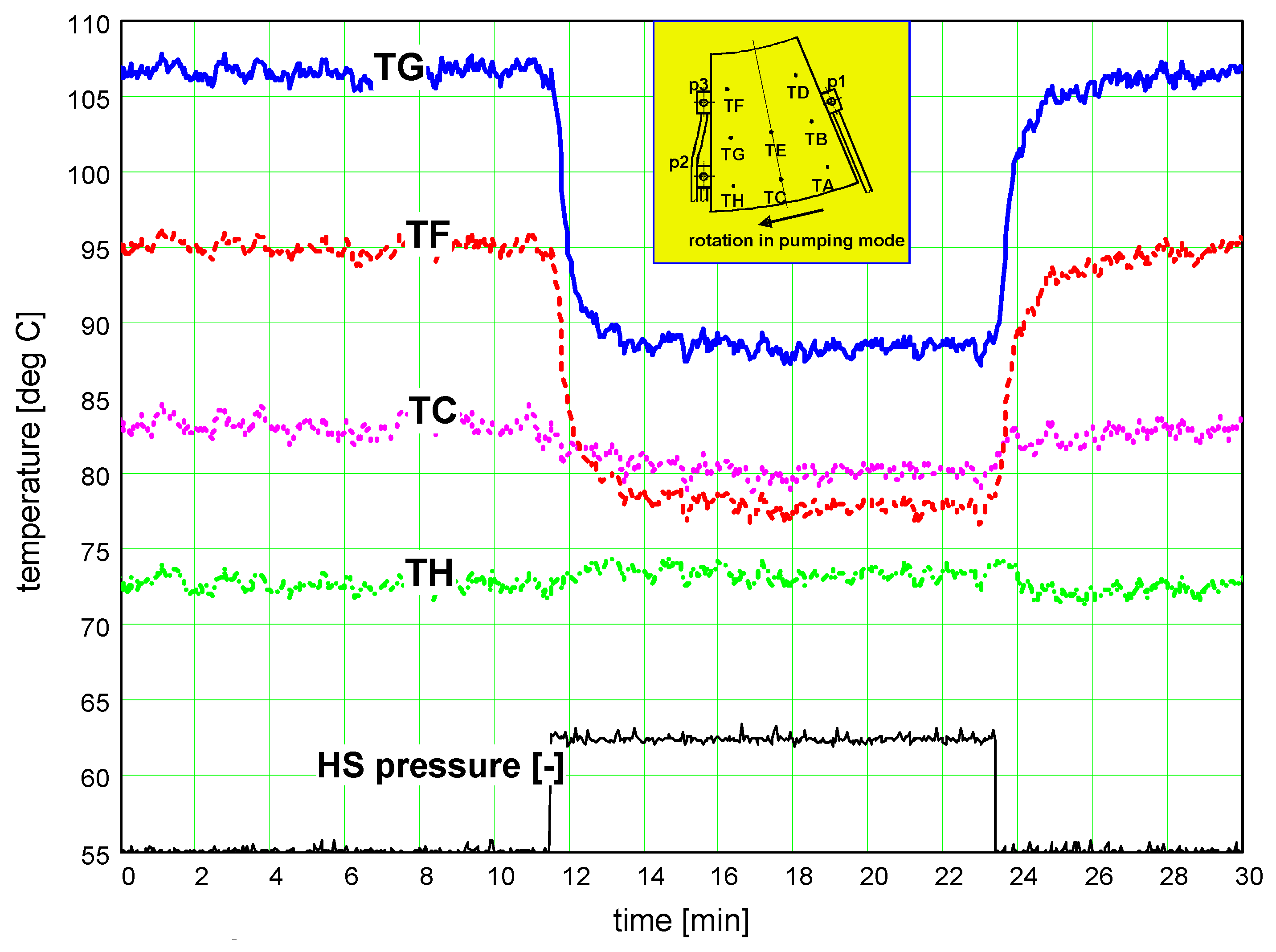
The results of a test run in the pumping mode with the use of the hydrostatic jacking system are shown in Figure 4. The graph illustrates a large and prompt effect of the switching on the hydrostatic jacking system on the temperatures of the bearing surface. In some of the locations (TF and TG) the temperature drop was approximately 20 °C, while at the corner of the pad (location TH) the effect was hardly noticeable.
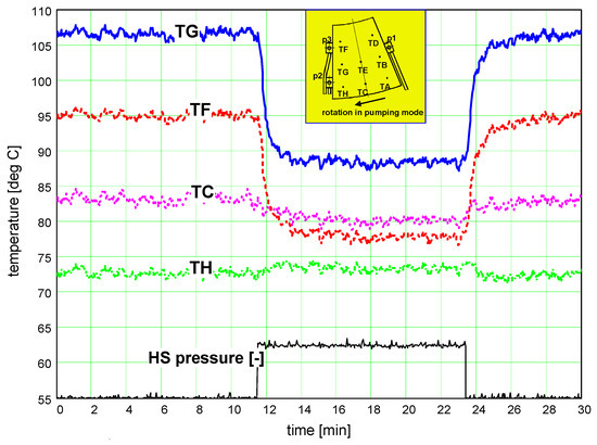
Figure 4.
Pad surface temperature during the hybrid operation of the thrust bearing [16].
The main results of the four steady state tests selected for presentation in the paper are shown in the following tables—the temperatures in Table 4 and film thickness in the vicinity of sensors positions in Table 5.
Table 4.
Bearing temperatures in the Unit 2 thrust bearing in selected operation regimes (oil bath temperature in all cases Toil = 44 °C).
Table 5.
Measured film thickness in the vicinity of sensors positions in generating and pumping mode in Unit 1.
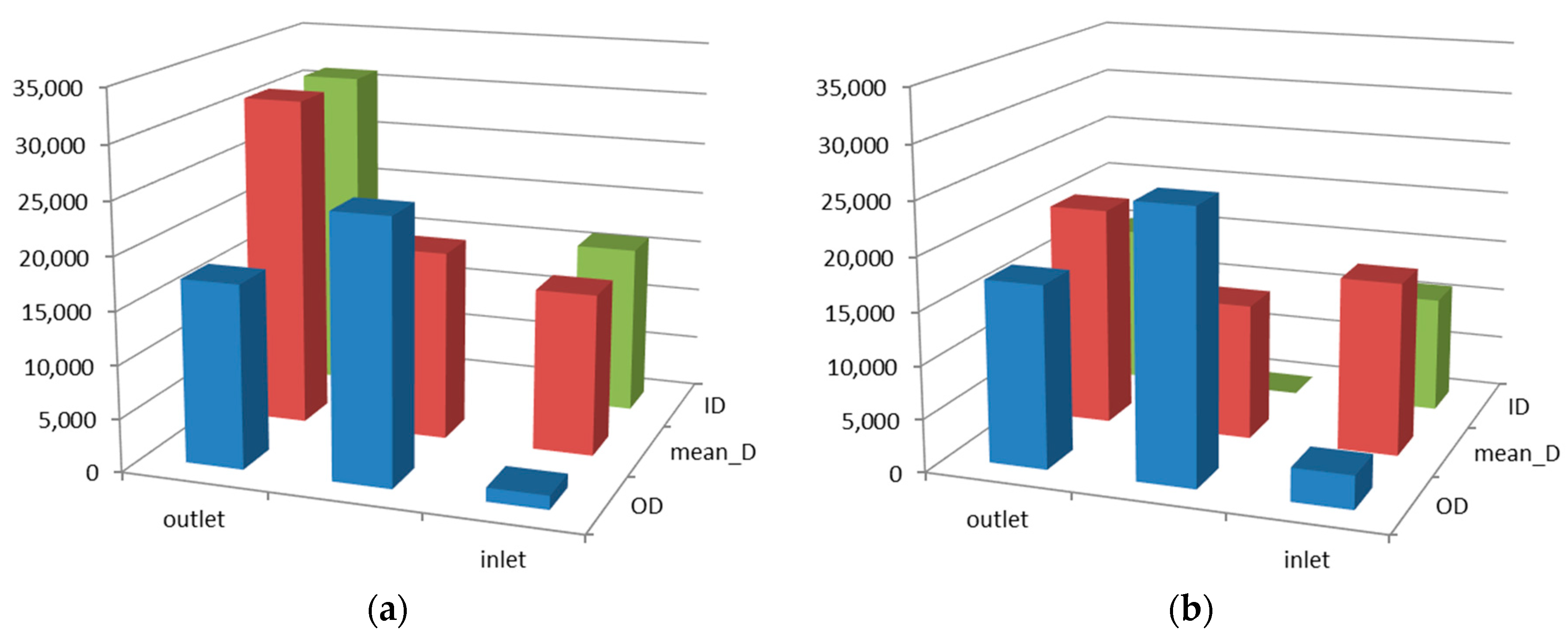
The distribution of the temperature at the pad surface in selected locations (TA–TH—see Figure 3) are shown in Figure 5 and Figure 6. The results are based on linear extrapolation of measured temperatures as explained in Figure 3. Temperatures in the generating mode are shown in Figure 5, with standard hydrodynamic operation in Figure 5a, and hybrid operation, with the hydrostatic pump switched on in steady-state mode in Figure 5b. Results of the pumping mode in hydrodynamic and hybrid regimes are shown in the same manner in Figure 6. One can see distinct differences between both regimes. In the hydrodynamic regime there is an increase of temperature along the film from the inlet to the outlet, most clearly seen at the mean diameter (red bars)—the increase is equal to 30 °C in the generating mode and 34 °C in the pumping mode. In comparison, in the hybrid regime the temperature rise is equal to only 13 and 24 °C, for generating and pumping, respectively. Higher maximum temperature and temperature rise in the pumping mode are probably the result of higher axial load, but exact data are not known. Due to lower temperature at the surface, the pad in the hybrid regime is less deformed. On the basis of similar measurements in the same bearing, which were published in [15], the pad thermal deformations were assessed as 15–25 µm in various modes of transient operation, in the steady state they are probably close to 15 µm. It is also likely that the film is thicker in hybrid mode—this is only indirectly known from comparisons of the film thickness in transient states [15]. Altogether the temperature in the hybrid regime is lower, by 7–7.3 °C, but the temperature at the outer radius is higher for the hybrid mode, which may be the result of the larger radial inclination of the pad and smaller thermal deformation. Another interesting observation is the lower inlet temperature of the pad in hybrid mode, the difference is approximately 3–3.6 °C in both modes, and this is the result of lower surface temperature (and most probably also the film temperature). The runner temperature is also likely to be lower due to cooler film and better heat exchange.
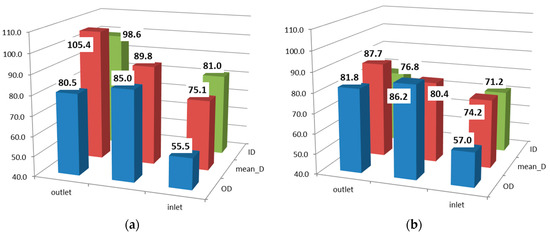
Figure 5.
Pad surface temperatures (°C)—generating mode, (a) hydrodynamic operation, and (b) hybrid operation.
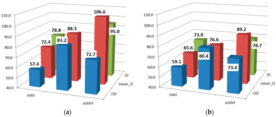
Figure 6.
Pad surface temperatures (°C)—pumping mode, (a) hydrodynamic operation, and (b) hybrid operation.
3.2. Heat Dissipation through the Bearing Pad
Apart from surface temperature distribution, shown above, the acquired data in the form of temperatures in 16 locations in the pad enable one to study the heat flow through the pad. The heat generated in the film is a result of shearing of the viscous lubricant. A significant part of the heat is transported to the oil bath by the oil itself, but some is conducted through the pad and then, due to the convection at the pad walls, is transported to the oil bath. The rest of the heat is conducted through the collar to the shaft, but also by convection at the sides of the collar immersed in the oil bath. Assuming that the heat flow is perpendicular to the sliding surface it is possible to calculate the local heat flux at the surface of the pad, on the basis of a formula:
where:
- h—pad thickness −0.06 m
- λ—thermal conductivity coefficient of pad material −50 W/mK
- Ts—temperature at the surface of the pad °C
- Tb—temperature at the bottom of the pad °C.
Neither temperature at the surface nor at the bottom of the pad is known from direct measurement, but the difference of temperatures between the pad sliding surface and the bottom is extrapolated on the basis of the temperatures measured at the sensors’ positions, with the upper sensor close to the sliding surface and the lower sensor close to the bottom, as explained in Figure 3.
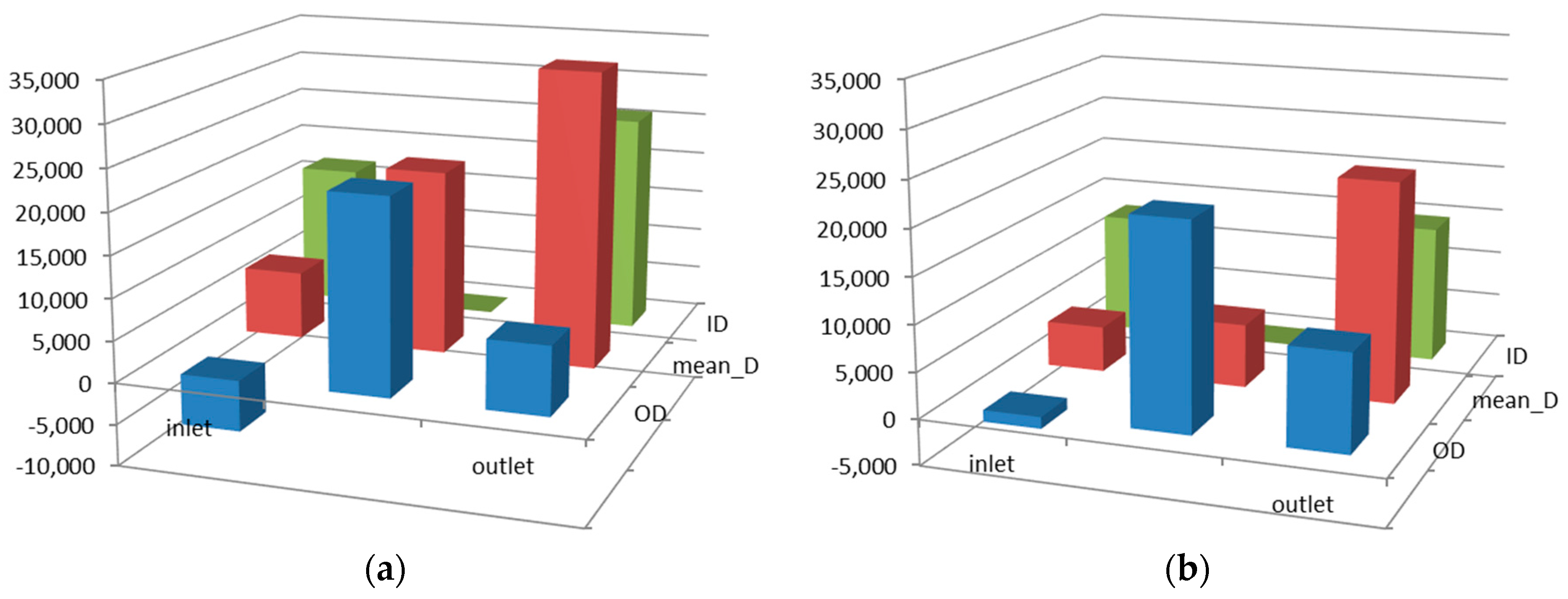
The results for the described cases are shown in the following graphs. Figure 7 shows heat flux distribution in generating mode, while Figure 8 shows distribution in pumping mode.
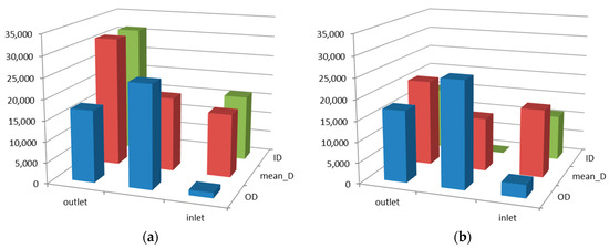
Figure 7.
Heat flux (W/m2) at the pad surface for generating mode at 80 MW: (a) normal (hydrodynamic) mode of operation; and (b) the hybrid mode of operation.

Figure 8.
Heat flux (W/m2) at the pad surface for pumping mode: (a) normal (hydrodynamic) mode of operation; and (b) hybrid mode of operation.
On the graphs one can observe that local heat flux in hydrodynamic operation is much larger than in hybrid operation and reaches 35 kW/m2, as compared to a maximum of 25 kW/m2. In the hybrid operation heat flux is more evenly distributed at the pad surface. The data is also shown in Table 6—in the hybrid regime the average heat flux is by 20–30% lower than in normal hydrodynamic operation. With the simplifying assumption that the heat is dissipated from all the pad walls (bottom and sides) with the same intensity the total amount of the heat dissipated from the pad through its wall was assessed and is shown in Table 6—quite obviously, proportionally to the average heat flux, the amount of heat is by 20–30% lower in hybrid regime in comparison to hydrodynamic regime. Bearing in mind that the total power loss is approximately 250 kW, the heat dissipated through the pad is approximately 10% in hydrodynamic regime, and considerably less in the hybrid regime.
Table 6.
Heat flux at the pad surface for various regimes of operation.
As a result of the smaller temperature gradient and the lower heat flux conducted across the pad one can expect smaller thermal deformations of the pad. Unfortunately in the further stages of the research two out of three proximity probes failed so there were no reliable film thickness measurement results, but discussing the reasons of the lower temperature of the pad and smaller heat flux, it is necessary to mention a couple of reasons:
There is a supply of cooler oil from the hydrostatic system directly to the central part of the film—contrary to the hydrodynamic lubrication where a mixture of cold and hot oil is supplied to the leading edge.
Most likely the film thickness is larger in the case of hybrid operation. Then, due to the thicker film, the flow of the oil is greater and a larger part of the heat is transported with the oil, and the share of the heat conducted through the pad is smaller.
3.3. Friction Loss in Hydrodynamic and Hybrid Regime—Comparison
With a thicker fluid film a smaller shearing gradient will occur in the film, which should result in a decrease of the friction loss in the film, but an increased viscosity due to decreased oil temperature acts in the opposite direction. In this case it is not easy to assess the scale of counteracting effects.
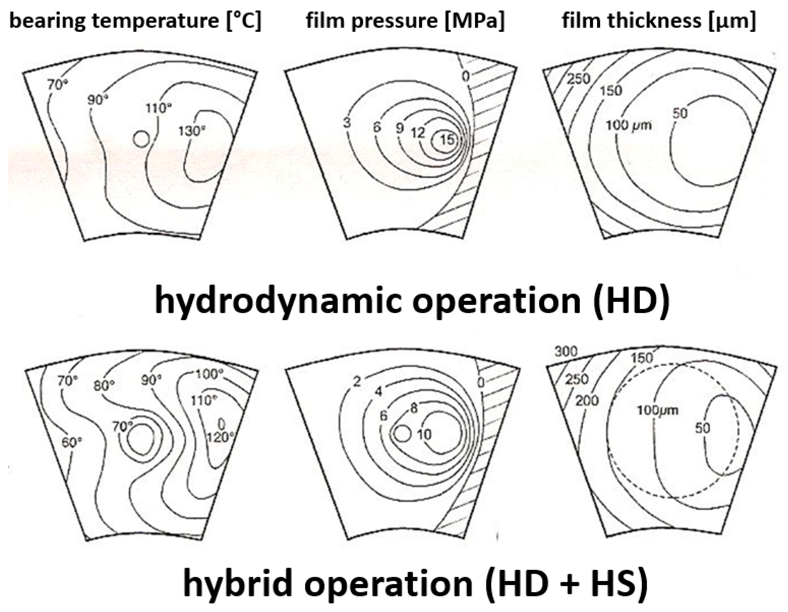
Ettles et al. [10] presented the study of the hydrostatically-assisted start-up of a hydraulic machine. Figure 9 shows the results of calculations of temperature distribution, film pressure, and film profile performed for a bearing of OD = 2 m, ID = 1 m, at 500 rpm, for both hydrodynamic operation (the upper graphs) and hybrid operation (the lower graphs). One can see that the film is thicker and the temperature is significantly lower in hybrid operation. With the use of the presented graphs it is possible to assess the friction losses in the film in both modes of operation by dividing the pad area into smaller parts. Then it is possible to identify the average local film thickness, local temperature and, on this basis, also local viscosity [17]. According to such calculation, the friction losses in the film (per whole bearing) is equal to 236 kW in a hydrodynamic bearing and 292 kW (24% increase) in a bearing in a hybrid mode. The result shows that the benefit of larger thickness and lower shearing rate was not sufficient to compensate the effect of lower temperature and increased viscosity. On the other hand, due to the increase of the film thickness, the increase of losses is smaller than the increase of viscosity (44%) at the average temperature, which is about 15 °C lower in HD mode than in hybrid mode. Further calculations show that if the film had been approximately 25 µm thicker, the effect of the increased viscosity would have been compensated. The above results are only a comparison of shearing losses in the film. It has to be pointed out that running in hybrid mode requires operation of a high-pressure oil pump, with additional energy consumption.

Figure 9.
Temperature, film pressure, and film thickness in a large tilting pad thrust bearing in hydrodynamic and hybrid operation [10].
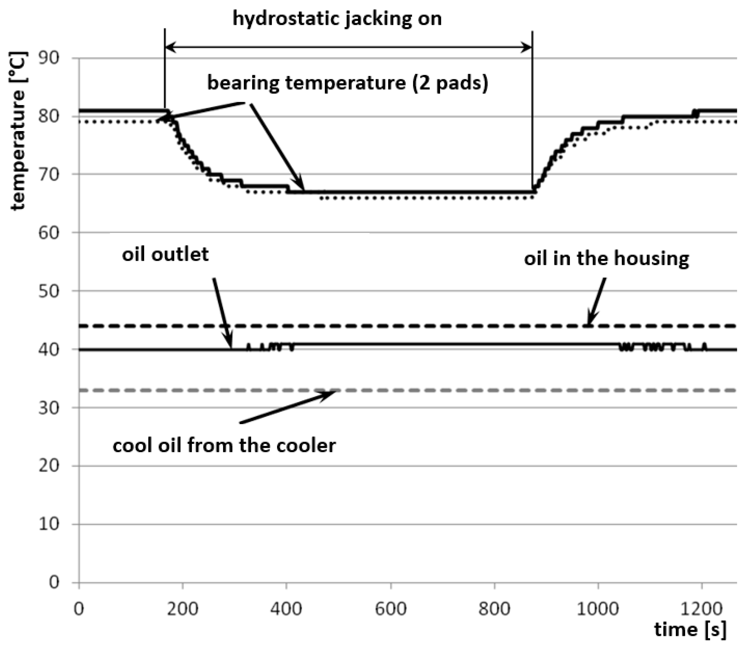
Similar experimental evidence of differences in losses in hydrodynamic and hybrid modes was also observed in the research described in this paper. Due to the operation of an external cooling system with a volumetric pump and measurement of temperatures of the oil drained from the oil bath and the oil supplied back to the bearing and the losses in the bearing can be estimated on the basis of heat balance—in contrast to the calculations described above, in this case estimated losses comprise the total loss in a thrust and radial bearing, including losses due to mixing of the oil in the bearing housing. Other components of the heat balance, e.g., convection at the external walls of the housing, were assessed as negligible. The graph at Figure 10 shows the data acquired during the test run during the pumping mode with the high-pressure pump switched on for approximately 15 min. It was the same test run as shown in Figure 4, but data from different sensors are shown here—temperatures are measured by the sensors installed in the middle of the pad. The temperature of the oil drained from the housing increased by 1 °C from 40 to 41 °C 3.5 min after switching on the hydrostatic jacking system, while the temperature of the oil supplied to the oil bath was equal to 32 °C and did not change. The losses are equal to 245 and 280 kW, respectively, for hydrodynamic and hybrid operation, according to the formula:
where:

Figure 10.
Changes of temperature of the bearing pads and oil during the test in hybrid mode.
- Q bearing losses [W]
- qoil oil flow—20.5 × 10⁻³ m3/s (1230 L/min)
- coil oil specific heat—1950 J/kg∙K
- ρoil oil density—875 kg/m3
- thot temperature of the oil drained from the bearing housing (°C)
- tcold oil temperature after the cooler (°C)
Assuming that the losses in the radial bearing are approximately 50 kW and do not depend on the mode of operation of the thrust bearing, one can calculate that the losses in hybrid operation increased by 35 kW, which is approximately 14%. In this calculation pumping power has not been considered, it increases power losses in hybrid mode, but the calculation based on the data of the hydrostatic jacking system (p = 13 MPa and QHS = 25 L/min) shows that pumping power of approximately 5.5 kW is small in comparison to shearing losses.
At the same time the average temperature at the bearing sliding surface dropped by 7 °C, from 82 to 75 °C, undoubtedly increasing the bearing safety margin. In parallel, however, viscosity increased by about 30%.
4. Conclusions
Selected results of extensive field tests with detailed measurements of thrust bearing operational parameters are presented in this paper, including operational results in a non-standard hybrid regime.
Bearing temperature is substantially lower during operation in the hybrid regime, which improves bearing reliability. Due to lower temperatures thermoelastic deformations of the bearing pads are smaller. Most probably the minimum film thickness is larger, but this has not been proven by direct measurements.
In hybrid mode, heat dissipation through the pads is smaller, with a heat flux 20–30% smaller than in standard hydrodynamic operation, it also means that the share of the heat dissipated through the pads is smaller, and probably a larger part of the heat generated in the film is transported by the oil.
Despite thicker films and smaller shearing gradients in hybrid modes, the test results, as well as the calculations, show that friction losses are larger due to the increased viscosity of cooler oil.
Author Contributions
In the research described in this paper the experiments were conceived and planned by Leszek Dąbrowski and Michał Wasilczuk; run by Leszek Dąbrowski, Michał Wodtke and Michał Wasilczuk; Michał Wasilczuk and Leszek Dąbrowski analysed the data; Michał Wodtke carried out the literature search and Michał Wasilczuk wrote the paper.
Conflicts of Interest
The authors declare no conflict of interest.
References
- Gardner, W.W. Tilting Pad Thrust Bearing Tests—Influence of Pivot Location. J. Tribol. 1988, 110, 609–613. [Google Scholar] [CrossRef]
- Neal, P.B.; Soliman, M.A.M. The Influence of Pivot Location on the Performance of Tilting-Pad Thrust Bearings. In Proceedings of the IMechE, Seminar on Plain Bearings—Energy, Efficiency and Design, London, UK, 10 November 1982. [Google Scholar]
- Ettles, C.M.M. Size Effects in Tilting Pad Thrust Bearings. Wear 1980, 59, 231–245. [Google Scholar] [CrossRef]
- Kawaike, K.; Okano, K.; Furukawa, Y. Performance of a Large Thrust Bearing with Minimized Thermal Distortion. ASLE Trans. 1979, 22, 125–134. [Google Scholar] [CrossRef]
- Ettles, C.M.M.; Anderson, H.G. Three-dimensional Thermoelastic Solutions of Thrust Bearings Using Code Marmac 1. J. Tribol. 1991, 113, 405–412. [Google Scholar] [CrossRef]
- Glavatskih, S.B.; Fillon, M. TEHD Analysis of Thrust Bearings with PTFE-Faced Pads. J. Tribol. 2006, 128, 49–58. [Google Scholar] [CrossRef]
- Heinrichson, N.; Santos, I.F.; Fuerst, A. The Influence of Injection Pockets on the Performance of Tilting—Pad Thrust Bearings. Part I: Theory. J. Tribol. 2007, 129, 895–903. [Google Scholar] [CrossRef]
- Ettles, C.M. Hot Oil Carry Over in Thrust Bearings. Proc. IMechE Part J J. Eng. Tribol. 1969, 184, 75–81. [Google Scholar]
- Ettles, C.M.; Knox, R.T.; Ferguson, J.H.; Horner, D. Test Result for PTFE-faced Thrust Pads, with Direct Comparison against Babbitt-Faced Pads and Correlation with Analysis. J. Tribol. 2003, 125, 814–823. [Google Scholar] [CrossRef]
- Ettles, C.M.M.; Seyler, J.; Bottenschein, M. Some Effects of Start-Up and Shut-Down on Thrust Bearing Assemblies in Hydro-Generators. J. Tribol. 2003, 125, 824–832. [Google Scholar] [CrossRef]
- Yuan, J.H.; Medley, J.B.; Ferguson, J.H. Spring-supported Thrust Bearings Used in Hydroelectric Generators: Comparison of Experimental Data with Numerical Predictions. Tribol. Trans. 2001, 44, 27–34. [Google Scholar] [CrossRef]
- Dąbrowski, L.; Wasilczuk, M. Evaluation of a Water Turbine Hydrodynamic Thrust Bearing Performance on the Basis of Thermoelastohydrodynamic Calculations and Operational Data. Proc. IMechE Part J J. Eng. Tribol. 2004, 218, 413–421. [Google Scholar] [CrossRef]
- Wodtke, M.; Schubert, A.; Fillon, M.; Wasilczuk, M.; Pajączkowski, P. Large Hydrodynamic Thrust Bearing: Comparison of the Calculations and Measurements. Proc. IMechE Part J J. Eng. Tribol. 2014, 228, 974–983. [Google Scholar] [CrossRef]
- Huang, B.; Wu, Z.D.; Wu, J.L.; Wang, Q.L. Numerical and Experimental Research of Bidirectional Thrust Bearings Used in Pump-turbines. Proc. IMechE Part J J. Eng. Tribol. 2012, 226, 795–806. [Google Scholar] [CrossRef]
- Dąbrowski, L.; Wasilczuk, M. Influence of Hydrostatic Pump Operation Period on Performance of a Thrust Bearing of a 125 MW Pump-turbine. Mec. Ind. 2004, 5, 3–9. [Google Scholar] [CrossRef]
- Dąbrowski, L.; Wasilczuk, M. Hydrostatic Lift Used in a Steady State Operation of a Water Turbine Thrust Bearing. In Proceedings of the 12th Nordic Symposium on Tribology, NORDTRIB NT-2006-10-89, Helsingør, Denmark, 7–9 June 2006; pp. 1–10. [Google Scholar]
- Wasilczuk, M. Large Hydrodynamic Thrust Bearings; ITEE: Radom, Poland, 2012. (In Polish) [Google Scholar]


© 2017 by the authors. Licensee MDPI, Basel, Switzerland. This article is an open access article distributed under the terms and conditions of the Creative Commons Attribution (CC BY) license (http://creativecommons.org/licenses/by/4.0/).