Figure 1.
Two simple models for the plastic deformation of solids. In the rigid-plastic model (a) the solid does not deform until the stress reaches a critical value (the penetration hardness) where it start to flow in such a way that the contact stress is always equal to the penetration hardness. In the elastoplastic model (b) the solids deform as a linearly elastic material until the local stress reaches the penetration hardness where it starts to flow in such a way that the contact stress is always equal to penetration hardness or below.
Figure 2.
Indentation of a solid exhibiting no work-hardening (a), and with work-hardening (b).
Figure 2.
Indentation of a solid exhibiting no work-hardening (a), and with work-hardening (b).
Figure 3.
Semi-crystalline polymers have small crystalline domains (lamella) surrounded by an amorphous matrix. During plastic deformation (resulting e.g., from polishing or tumbling) this generates a rough surface.
Figure 3.
Semi-crystalline polymers have small crystalline domains (lamella) surrounded by an amorphous matrix. During plastic deformation (resulting e.g., from polishing or tumbling) this generates a rough surface.
Figure 4.
Relaxation of the force as a function of the logarithm of time while being confined between two flat steel surfaces. The compression starts at time and lasts . After this, the position of the surfaces is kept fixed.
Figure 4.
Relaxation of the force as a function of the logarithm of time while being confined between two flat steel surfaces. The compression starts at time and lasts . After this, the position of the surfaces is kept fixed.
Figure 5.
Plastic deformation of the sandblasted polymer ball (schematic). After squeezing the ball against a flat steel or glass surface, a small circular (radius ) flattened surface region is formed due to plastic deformation in a small volume element inside the polymer. In addition, the asperities in the flattened region are plastically deformed due to the high local stresses which prevail at short enough length scales.
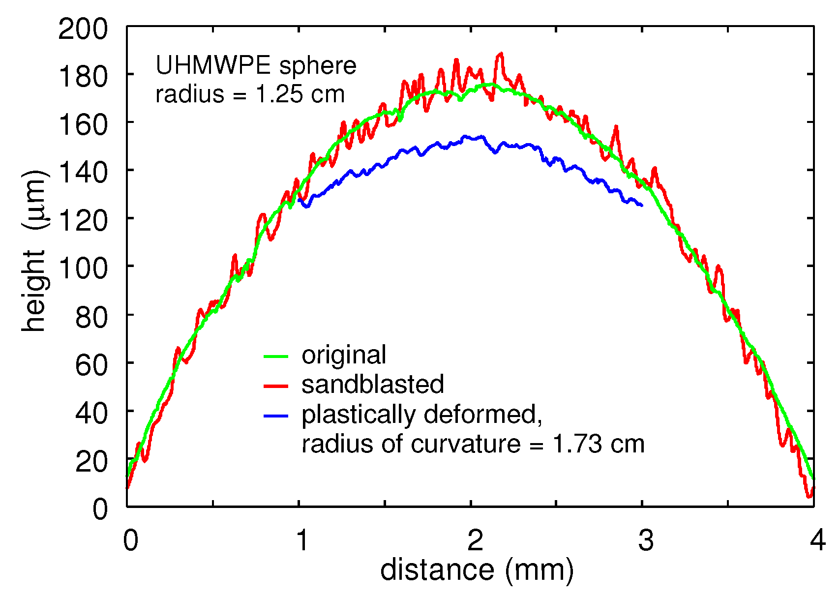
Figure 6.
The measured surface height of the untreated (green), the sandblasted (red), and the final, plastically deformed (blue) UHMWPE polymer sphere to which a squeezing force of ≈465 N had been applied for 10 min by two flat steel surfaces. The radius of curvature of the original and the sandblasted sphere is ≈1.25 . It increases to ≈1.73 in the plastically deformed region.
Figure 7.
The surface height as a function of the distance along a straight line for the sandblasted UHMWPE sphere (red), and for the plastically deformed surface (blue) after removing the macroscopic curvature.
Figure 7.
The surface height as a function of the distance along a straight line for the sandblasted UHMWPE sphere (red), and for the plastically deformed surface (blue) after removing the macroscopic curvature.
Figure 8.
The surface height probability distribution as a function of the surface height for the sandblasted UHMWPE surface (red) and the plastically deformed surface (blue). The macroscopic surface curvature is removed in both cases.
Figure 8.
The surface height probability distribution as a function of the surface height for the sandblasted UHMWPE surface (red) and the plastically deformed surface (blue). The macroscopic surface curvature is removed in both cases.
Figure 9.
The 1D surface roughness power spectrum as a function of the wavenumber (log–log scale) for the sandblasted UHMWPE polymer sphere (red), and from the plastically deformed surface area (blue).
Figure 9.
The 1D surface roughness power spectrum as a function of the wavenumber (log–log scale) for the sandblasted UHMWPE polymer sphere (red), and from the plastically deformed surface area (blue).
Figure 10.
TEM micrograph of UHMWPE showing crystalline regions (lamella) and amorphous regions on the length scale of ∼1
m. Adapted from Ref. [
18].
Figure 10.
TEM micrograph of UHMWPE showing crystalline regions (lamella) and amorphous regions on the length scale of ∼1
m. Adapted from Ref. [
18].
Figure 11.
The surface height as a function of the distance along a straight line for the sandblasted UHMWPE sphere (red), and for the plastically deformed surface (blue) after removing the macroscopic curvature.
Figure 11.
The surface height as a function of the distance along a straight line for the sandblasted UHMWPE sphere (red), and for the plastically deformed surface (blue) after removing the macroscopic curvature.
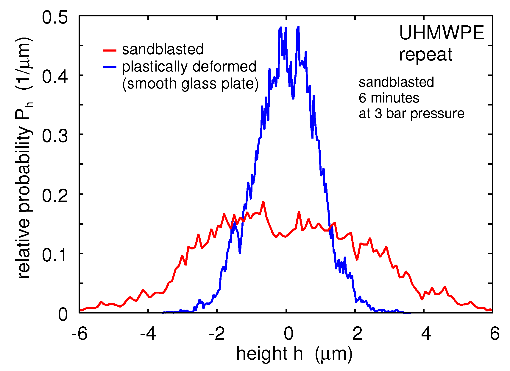
Figure 12.
The surface height probability distribution as a function of the surface height for the sandblasted UHMWPE surface (red) and the plastically deformed surface (blue). In all cases the macroscopic surface curvature is removed.
Figure 12.
The surface height probability distribution as a function of the surface height for the sandblasted UHMWPE surface (red) and the plastically deformed surface (blue). In all cases the macroscopic surface curvature is removed.
Figure 13.
The 1D surface roughness power spectrum as a function of the wavenumber (log–log scale) for the sandblasted UHMWPE polymer sphere (red), and from the plastically deformed surface area (blue).
Figure 13.
The 1D surface roughness power spectrum as a function of the wavenumber (log–log scale) for the sandblasted UHMWPE polymer sphere (red), and from the plastically deformed surface area (blue).
Figure 14.
The surface height probability distribution as a function of the surface height for the sandblasted Nylon 66 surface (red) and the plastically deformed surface (blue). In all cases, the macroscopic surface curvature is removed.
Figure 14.
The surface height probability distribution as a function of the surface height for the sandblasted Nylon 66 surface (red) and the plastically deformed surface (blue). In all cases, the macroscopic surface curvature is removed.
Figure 15.
The 1D surface roughness power spectrum as a function of the wavenumber (log–log scale) for the sandblasted Nylon 66 polymer sphere (red), and from the plastically deformed surface area (blue).
Figure 15.
The 1D surface roughness power spectrum as a function of the wavenumber (log–log scale) for the sandblasted Nylon 66 polymer sphere (red), and from the plastically deformed surface area (blue).
Figure 16.
The surface height probability distribution as a function of the surface height for the sandblasted PP surface (red) and the plastically deformed surface (blue). In all cases the macroscopic surface curvature is removed.
Figure 16.
The surface height probability distribution as a function of the surface height for the sandblasted PP surface (red) and the plastically deformed surface (blue). In all cases the macroscopic surface curvature is removed.
Figure 17.
The 1D surface roughness power spectrum as a function of the wavenumber (log–log scale) for the sandblasted PP polymer sphere (red), and from the plastically deformed surface area (blue).
Figure 17.
The 1D surface roughness power spectrum as a function of the wavenumber (log–log scale) for the sandblasted PP polymer sphere (red), and from the plastically deformed surface area (blue).
Figure 18.
The surface height probability distribution as a function of the surface height for the sandblasted PP surface (red) and the plastically deformed surface (blue). In all cases the macroscopic surface curvature is removed.
Figure 18.
The surface height probability distribution as a function of the surface height for the sandblasted PP surface (red) and the plastically deformed surface (blue). In all cases the macroscopic surface curvature is removed.
Figure 19.
The 1D surface roughness power spectrum as a function of the wavenumber (log–log scale) for the sandblasted PP polymer sphere (red), and from the plastically deformed surface area (blue).
Figure 19.
The 1D surface roughness power spectrum as a function of the wavenumber (log–log scale) for the sandblasted PP polymer sphere (red), and from the plastically deformed surface area (blue).
Figure 20.
The surface height probability distribution as a function of the surface height for the sandblasted PTFE surface (red) and the plastically deformed surface (blue). In all cases the macroscopic surface curvature is removed.
Figure 20.
The surface height probability distribution as a function of the surface height for the sandblasted PTFE surface (red) and the plastically deformed surface (blue). In all cases the macroscopic surface curvature is removed.
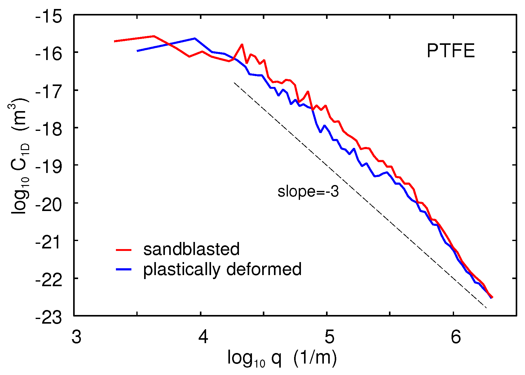
Figure 21.
The 1D surface roughness power spectrum as a function of the wavenumber (log–log scale) for the sandblasted PTFE polymer sphere (red), and from the plastically deformed surface area (blue).
Figure 21.
The 1D surface roughness power spectrum as a function of the wavenumber (log–log scale) for the sandblasted PTFE polymer sphere (red), and from the plastically deformed surface area (blue).
Figure 22.
The surface height probability distribution for the sandblasted PC surface (red), and the plastically deformed surface (blue). In all cases, the macroscopic surface curvature is removed.
Figure 22.
The surface height probability distribution for the sandblasted PC surface (red), and the plastically deformed surface (blue). In all cases, the macroscopic surface curvature is removed.
Figure 23.
The 1D surface roughness power spectrum as a function of the wavenumber (log–log scale) for the sandblasted PC polymer sphere (red), and from the plastically deformed surface area (blue).
Figure 23.
The 1D surface roughness power spectrum as a function of the wavenumber (log–log scale) for the sandblasted PC polymer sphere (red), and from the plastically deformed surface area (blue).
Figure 24.
The plastic contact area as a function of the logarithm of the magnification (upper scale) or the largest wavenumber
q of the roughness included in the calculation (lower scale). In the calculations we have used the measured surface roughness power spectra of the sandblasted polymer balls, penetration hardness from the conical indenter (see
Table 1) and the Young’s elastic modulus from the literature [
23] (
, 2.1, 1.2, 1.25 and
for PTFE, PC, nylon, UHMWPE and PP, respectively).
Figure 25.
Line scan of (a) the original, and [(b) and (c)] the plastically deformed surface (schematic). (a) A solid with random roughness is squeezed against a rigid, perfectly flat countersurface. (b) In the ideal (theoretical) model description, the surface roughness in the contact regions is perfectly smoothed, resulting in flat regions parallel to the squeezing plane. (c) In reality (experiment), due to inhomogeneous plastic flow at short length scales, the plastically flattened surface area exhibits surface roughness.
Figure 26.
The surface height as a function of the lateral coordinate x for the UHMWPE sandblasted and plastically deformed surface (red), and after removing the macroscopic curvature, assumed to be a segment of a circle (blue). Note that except for the random roughness the blue curve is a straight line, i.e., the original profile is (except for the random roughness) a segment of a circle.
Figure 27.
The surface height of the original and plastically deformed UHMWPE-ball, after removing the external load , as obtained from the FEM simulation.
Figure 27.
The surface height of the original and plastically deformed UHMWPE-ball, after removing the external load , as obtained from the FEM simulation.
Figure 28.
Plot of the Von Mises stress in the UHMWPE-ball when it is squeezed against a rigid flat surface with the force .
Figure 28.
Plot of the Von Mises stress in the UHMWPE-ball when it is squeezed against a rigid flat surface with the force .
Table 1.
Information on (plastic) deformation experiments. Regular numbers relate to parallel plate geometries; those in round brackets to conical steel indenter. The diameter of the circular, plastically deformed region is denoted by . The (apparent) hardness is defined by , where is the maximum applied squeezing force (load). The root-mean-square (rms) roughness amplitude is given for the sandblasted surfaces, and for the plastically deformed surfaces (in square brackets).
| Polymer | (mm) | (MPa) | | rms (m) |
|---|
| PTFE | 5.8 (3.0) | 17 1(64) | 29 (45) | 3.0 [2.3] |
| UHMWPE | 4.5 (2.7) | 28 1(82) | 47 (50) | 4.1 [1.6] |
| PP | 3.2 (2.2) | 56 (117) | 25 (50) | 7.8 [4.1] |
| Nylon 66 | 3.2 (1.3) | 56 (324) | 19 (30) | 2.0 [2.0] |
| PC | 2.7 (1.5) | 77 (258) | 12 (43) | 2.5 [1.6] |


