1. Introduction
The behaviour of an oil-film journal bearing is influenced by the temperature distribution in the bearing caused by the heat generated by shear stresses in the oil-film, especially in high-speed machines. This influence occurs mainly due to the high dependence of the oil viscosity on temperature, the thermal deformations in the bearing, and the thermal expansions in the shaft.
In fact, the increase in the temperature of the oil-film corresponds to the reduction of the oil viscosity and, consequently, to the reduction in the minimum oil-film thickness, which has high risk of wear due to the possible occurrence of a mixed-lubrication regime. For industrial oils, such as ISO VG32 and ISO VG46 oil grades, the slope of the temperature-viscosity curve is higher, in correspondence with the typical oil inlet temperature of oil-film bearings in rotating machinery, i.e., 40 °C. For instance, Vijayaraghavan and Brewe, in [
1], investigated, by simulation, the effect of the temperature in the performance of a journal bearing by using the Roelands’ model on the viscosity-temperature/pressure relationship.
Glavatskih et al. in [
2] investigated the effect of oil thermal properties for a thrust bearing, suggesting the use of synthetic oils or improvers for mineral oils as a way to improve the viscosity-temperature relationship and increase the bearing load carrying capacity.
The secondary effect of high temperature in the bearing is the thermal deformation in the pads and bearing housing and the thermal expansion in the shaft. By considering the oil-film, the maximum temperature is obtained at the interface with the pad, close to the trailing edge. Therefore, a high-temperature gradient originates in the pad along the radial direction. This results in the thermal bending of the pad about the pivot position in the circumferential direction for line-contact pads and in axial direction for pads with point or ball-socket contact. For line-contact pads this corresponds to the increase of the radius of the curvature of the pad, that is, the increase of both the machined clearance and preload factor . The main effect of the increase in the machined clearance is the change in the pressure distribution in the oil-film with an increase in the maximum pressure in correspondence with the centre of the loaded pad.
Furthermore, the effect of the thermal expansion of the shaft is the reduction of the assembled clearance (or increase in the preload factor), which corresponds to the reduction of oil-film thickness in all the pads. The thermal expansion of the bearing housing can also affect the real assembled clearance. In any event, the total effect of the shaft-housing thermal expansion and deformation is a reduction of the bearing clearance. In general, the change of the pad geometry leads to the reduction in the oil-film thickness and the increase in the maximum pressure in the oil-film, with the already-mentioned risk of wear due to the occurrence of a mixed-lubrication regime.
Edney in [
3] presented an extensive experimental investigation of steady-state characteristics of TPJB. He concluded that the bearing clearance is the primary factor affecting pad temperature, which can be significantly reduced by increasing the bearing clearance.
Furthermore, the low friction tin-based Babbitt metals on the pads usually have a limited maximum operating temperature [
4]. Recently, attempts at using an aluminium-based layer on pads have been performed by bearing manufacturers for increasing the operating temperature range of the bearing. A maximum pad temperature of 100 °C is also a requirement of ISO and API standards for steam turbines and centrifugal compressor suppliers. Therefore, the predictions of the maximum oil-film temperature and the temperature distribution in the bearing are mandatory in the design phase of bearings in such applications.
Thermo-hydrodynamic (THD) and more recently thermo-elasto-hydrodynamic (TEHD) analyses are usually used for the prediction of pad metal temperature. Daniel and Cavalca in [
5] investigated the thermal effects of tilting-pad bearings by using THD analysis and a finite-volume method for the integration of the energy equation. Thorat et al. in [
6] compared pad temperature measurements with predictions using a TEHD model by investigating the effects of manufacturing tolerances on bearing assembled clearance and preload. The state of art of thermal models for tilting-pad journal bearings is represented by the work of Suh and Palazzolo in [
7], where they developed a full three-dimensional thermal model by including pad thermal deformation, shaft thermal expansion and pivot flexibility, and by the work of Rindi et al. in [
8], in which they improved the three-dimensional thermal model by including the model of the oil supply.
Oil-film bearings are mainly cooled by the cold inlet lubricating oil and by the heat exchange with the surroundings. Large oil-inlet flowrates are usually adopted and carefully selected for the reduction of the maximum temperature. The aim is to reduce the hot oil carry over phenomenon given by the hot oil exiting the previous pad and mixed with the supplied cold oil. As already observed by Edney in [
3], there is an optimum flowrate for obtaining the lowest maximum pad temperature, beyond which the temperature cannot be further reduced. This means that the replacement of lubricant between two consecutive pads is totally obtained, and the temperature of the oil at the leading edge of the pad is almost the same as that of the supplied oil. Therefore, the maximum temperature in the pad is mainly given by the heat generated by shear stresses and by the supply temperature, as experimentally investigated by Brito et al. in [
9] for journal bearings.
The control of the oil temperature at the leading edge of the pad can be achieved by the adoption of leading edge groove (LEG) bearings, which are able to reduce the hot oil carry-over phenomenon, as shown by Edney et al. in [
10,
11]. The reduction of the pad temperature can also be obtained by suitable nozzles of the oil inlet, as shown in [
12] or by suitable cooling circuits or devices inside the pads. Different circuits able to modify the entire temperature profile of a bearing have been described in several patents [
13,
14,
15,
16]. In these patents, the cold lubricating oil can naturally flow within channels, pipes or holes of the bearing, or are externally fed by a suitable nozzle system. Kawaike et al. in [
17] investigated the influence of thermal distortion on a large thrust bearing and proposed the adoption of tangential cooling ducts in the pads where the lubricating oil can naturally flow within them. The pads are comprised of two layers that are mechanically joined and the ducts are obtained by milling machining on the upper surface of the lower layer.
Najar and Harmain in [
18] investigated cooled pads for thrust bearings by simulating the thermal effect of incorporating a cooling circuit on a sector pad, to which water-cooling fluid is fed by an external pump. They observed that the overall temperature can be significantly reduced compared to traditional cooling systems. Najar and Harmain in [
19] improved the design of the cooling circuit by adding a bifurcation in the circuit in the middle of the pad. They observed in simulations that a significant amount of heat could be removed from the bearing with the increase of the cooling fluid flow velocity. The effect is the reduction of the maximum pressure in the oil film and the increase in the load carrying capacity of the bearing. However, in the theoretical analyses in [
18] and [
19], the manufacturing issues of the circuit in the pads are not investigated.
By means of computational fluid dynamics (CFD) simulations, Chatterton et al. in [
19] investigated the effect of several cross-sections and paths of the cooling circuit for a simple squared flat pad. Simplified boundary conditions were assumed in the simulations, and the results were compared to the reference solid pad without the cooling circuits. The highest temperature reduction could generally be achieved by increasing the inlet flowrate of the cooling fluid by using water as the cooling fluid and adopting a multi-channel cross-section. The authors in [
20] proposed solving the manufacturing issues due to the complex cross-sections of the cooling circuit by means of an additive manufacturing process.
In this paper, the idea of using cooled pads with internal channels in which an external cooling fluid is circulated, will be applied to a TPJB. The three-dimensional TEHD model of the TPJB equipped with a cooled pad will be described, and the results of the numerical simulations will be shown. Several analyses were performed in order to investigate the influences of cooling conditions, such as the type, flowrate, inlet temperature and number of cooled pads. Two types of pad geometry with different cross-sections of the cooling circuit, namely, circular and six-square multi-channel sections, were compared to the reference bearing with solid pads and without the internal cooling circuit.
Simple experimental tests were performed by means of a test rig equipped with a cooled pad bearing obtained with the additive manufacturing process, thus showing the effectiveness of the solution and the agreement with the predictions.
2. Bearing Description
The bearing is a five-pad rocker-backed TPJB installed in a load-on-pad configuration with a diameter of 100 mm and a length-to-diameter ratio of 0.7, as shown in
Figure 1a.
In
Figure 1a, only one cooled pad with its piping fittings is installed in the bearing along the direction of the load, which is the same configuration adopted in the experimental tests. The tangential position of the pads in
Figure 1a is maintained by five oil nozzles.
The geometrical characteristics of the bearing and the operating conditions considered in the paper are listed in
Table 1, where the load
acts on the downward vertical direction (Y axis in the scheme of
Table 1). The values of the geometrical characteristics of the bearing are the same as those of the real bearing considered in the experimental activity shown at the end of the paper.
Two geometries of the internal channels have been considered for the cooled pads: the simple circular cross-section (
Figure 1b) with a nominal diameter of approximately 8 mm and the more complex multi-channel cross-section composed of six square section channels with side length of approximately 2.9 mm each (
Figure 1c). The two geometries have the same cross-sectional area of 50 mm
2 and the same path length.
As evidenced in [
21], the multi-channel design allows for better cooling due to the increase of the exchanging surface between the cooling fluid and the pad. The multi-channel geometry considered in the analysis represents the optimal result of the investigation performed by the same authors in [
20] and is also given by the design constraints due to the limited dimension of the pad. The M-like path of the cooling circuit has been adopted in order to have the two fittings on the same side of the bearing to reduce any possible issues during the installation. All the pads are also equipped with a temperature probe placed approximately in the centre of the pads (see
Figure 1).
Three pads, namely, the solid pad without internal circuit and the pads with cooling circuits of circular and the six-square cross-sections, were manufactured using the same process. The overall manufacturing process includes the 3D printing with additive manufacturing of the metal powder of the back of the pad in AISI 316L steel (see
Figure 2a–f) adding a small amount of excess metal (0.5 mm) to the 3D geometry for finishing, the coating of anti-friction Ecka Tegostar material based on standard process of melting and centrifugation, the execution of threads and the finishing machining for obtaining the final pad dimensions and tolerances (see
Figure 2g). Please note that the 3D printing of the steel base part of the pad allows to obtain the surface roughness of approximately
= 20 μm and dimensional tolerances of approximately ±0.1 mm. In any case, these tolerances were taken into account by the small amount of excess metal on all the surfaces of the 3D printed part. Then, the excess metal was removed by the final finishing machining allowing the nominal dimension and geometry of the pad to be obtained. Conversely, the surfaces of the internal cooling channels have the same roughness and tolerance of the 3D printing process. The manufacturing process of the cooled pad differs only in the manufacture of the steel base part of the pad with respect to a standard pad. Therefore, the external geometry and dimensions of a standard pad and a 3D printed cooled pad are the same, with no influence on the final clearance of the bearing. The increase in the cost of each single cooled pad with respect to a standard pad has been estimated of approximately 20%. Nevertheless, the manufacturing process can be optimized, and the cost reduced, by performing the finishing machining only on surfaces that require tight dimensional tolerances.
3. Bearing Model
The TEHD model of the TPJB bearing is similar to that developed and described by the same authors in [
22,
23] and improved with respect to the thermal aspect, as partially undertaken in [
24] for sleeve journal bearings. The model primarily includes the laws of hydrodynamic lubrication, the three-dimensional thermal model of the oil-films, pads and shaft and the flexibility of the pivots. The deformation of the pad due to mechanical and thermal stresses has not been considered in the model in order to reduce the computational effort of the simulations.
For a given static load, some convergence and equilibrium conditions must be satisfied, such as the convergence of the distributions of the pressure in the oil-film of each pad and temperature in the system, as well as the equilibrium of the oil-film forces on each pad and shaft.
3.1. Bearing Geometry and Quantities
By considering the scheme of the pad-shaft system shown in
Figure 3 for the k-th pad, the vector of the
degrees of freedom of the system is as follows:
where
and
represent the shaft centre position
in the cartesian reference system
,
represents the tilt angle of the k-th pad, and
represents the displacement of the k-th pad along the radial direction due to the flexibility of the pivot. The flexibility
of the pivot along the
direction has been evaluated by means of the contact Hertz theory [
23]:
where
is the load acting on the k-th pivot,
and
are the diameters of the bearing housing and the back of pad respectively,
the contact length,
and
the Young’s modulus and the Poisson’s coefficient of the material of the two bodies, respectively.
3.2. Hydrodynamic Lubrication
The pressure distribution in each oil-film due to the lubrication mechanism was obtained by means of the well-known Reynolds equation:
where
is the tangential direction,
is the axial direction,
is the oil-film thickness,
is the pressure in the oil-film,
is the oil dynamic viscosity and
is the oil mass density. The velocity vector components of the shaft and the pads (point
and
in
Figure 3) are described by
and
, respectively, where
represents the velocity component along the tangential direction (
coordinate) and
the velocity component along the radial direction (
coordinate). At steady state
,
and
. In general, the velocity vector components
are obtained as the projection of the velocity of point
(see
Figure 3) along the tangential and normal directions, whereas
are obtained as the projection of the velocity of point
along the tangential and normal directions. The absolute velocities of points
and
are given as follows:
The pressure equation (3) was obtained based on Reynolds’ assumptions: laminar flow, negligible inertia forces, negligible compressibility of the fluid, Newtonian fluid, constant pressure in the film thickness and no slip between the fluid and the solid surface.
The dynamic viscosity
and the mass density
of the oil are assumed to be functions of the temperature
only:
where
and
are the viscosity index and the coefficient of thermal expansion of the oil, respectively.
3.3. Cavitation Problem
The cavitation problem has been solved using the “complementarity concept” [
25,
26]. In the active (non cavitated) region, the fluid density
is constant and equal to
. In the cavitated (non-active) region, the density becomes lower because of the presence of vapor and gas bubbles. In contrast, the pressure has a complementary behaviour. The pressure is zero in the cavitated region, whereas it has a greater value in the other parts of oil bearing. If pressure
is multiplied by
, then the Reynolds equation (3) can be rewritten as a complementary problem in the complementary variables
and
:
Equation (6) was solved using the finite different method. By discretizing the derivatives in Equation (6) on the grid, it is possible to obtain the pressure
and the complementary variable
at node
of the mesh grid as a combination of corresponding values of adjacent nodes. By considering all the nodes of the mesh grid, it is possible to obtain a linear system as follows:
where
is the column vector that contains the value of pressure for all the nodes of the grid domain used in the finite-difference method. Vectors
and
include unknown values
and
respectively, to be evaluated, and known values
and
are given by the boundary conditions (zero pressure or known density at boundaries). Therefore, by rearranging Equation (7), it follows:
Thus, the solution of complementary problem in the unknown variables
and
can be obtained using a linear complementarity problem (LCP) solver that is able to solve the following linear system:
where
3.4. Three-Dimensional Thermal Model
The three-dimensional thermal model allows the distribution of the temperature in the entire bearing to be obtained. The model includes a portion of the shaft (S), the oil-films (O) and the solid pads (P). The presence of a portion of the shaft of length equal to three times the length of the bearing allows the heat exchange of the shaft to be considered with a good approximation.
In a more realistic simulation, the whole shaft must be considered together with all heat sources and boundary conditions. In general, in a real rotating machine the heat can be generated by bearings (oil-film and rolling elements), electrical windings in electric motors and generators or steam and gas in turbines. Therefore, it is difficult to generalize and consider an equivalent shaft length. In general, if a single oil-film bearing is considered, the increase in shaft length leads to the increase in the heat exchange surface and calculation time. Therefore, a shaft length equal to three times the length of the bearing, constitutes a good compromise between all the mentioned conditions, allowing to estimate the axial distribution of the temperature in the shaft with a good approximation.
Steel was assumed to be the material for the solid pads and shaft parts.
The energy equation of each oil-film, assuming laminar flow, is as follows [
27]:
where
and
(in
) are the thermal conductivity and the heat capacity of the oil, respectively.
Heat conduction only occurs in the shaft and in the solid pads (at steady state):
where
and
are the thermal conductivity coefficients of the shaft and the solid pad, respectively.
Steel was assumed to be material for the shaft (), whereas steel and Babbit metal for the base part and the anti-friction layer with a thickness of 3 mm were assumed for the pads, respectively ().
Equations (11) and (12) were solved by means of the finite element method. The meshes used for the solid pads, the oil-films and the shaft are shown in
Figure 4.
The boundary conditions (BC) applied to the faces of the bodies of the model are listed in
Table 2.
Convective boundary conditions with the convection coefficients for all the surfaces in contact with the lubricating oil at supply temperature ( = 40 °C) and for the surfaces of the two portions of the shaft in contact with the air at room temperature ( = 30 °C).
The parts of the model (pads, oil-films and shaft) are connected to each other at interfaces or matching surfaces, where the temperatures and the heat fluxes of two adjacent parts are the same. By considering the
k-th oil-film body, these two conditions are (see
Figure 4):
The simulation code was developed in the MATLAB environment by using the optimization toolbox for solving the equilibrium position of the system, and the partial differential equation toolbox for solving the three-dimensional thermal model.
The default values of 400 maximum iterations and for the function tolerance have been used as stopping criteria of the solver for the equilibrium position of the system.
The thermal model of the cooled pad has been solved with ANSYS Fluent software (Canonsburg, PA, USA) to compute the heat transfer of the fluid path with a CFD simulation. An Ansys-MATLAB co-simulation was performed by integrating the thermal model of the cooled pad in the three-dimensional thermal model of the entire bearing (shaft, all the oil-films and the remaining solid pads). In the three-dimensional thermal model, the convergence of the temperature and heat flux at the interface between the cooled pad(s) and the corresponding oil-film(s) is reached by iteration, as shown in
Figure 5, and only one cooled pad was considered.
In
Figure 5, the arrows indicate the heat flux (in blue) and the temperature (in red) boundary conditions at interfaces required for the solution of each part of the model.
For example, by considering the oil-film #1 and the pad #1 in
Figure 5, the thermal model of the oil-film #1, which was implemented in MATLAB, gives the temperature distribution (red arrow) to be applied to the active surface of the cooled pad #1. The thermal model of the cooled pad #1 was implemented in Fluent, which in turn computes the heat transfer in the pad and generates the total heat flux (blue arrow) to be applied to the surface of the corresponding oil-film #1.
The flowchart of the thermal model is shown in
Figure 6, where the dashed arrows indicate the heat flux (in blue) and the temperature (in red) boundary conditions at interfaces required for the solution of each part of the model.
For example, by considering
Figure 6, for given initial heat fluxes from the oil models (blue arrows), the shaft model has been solved and its temperature distribution has been evaluated (red arrows). The oil models were solved by applying the temperature distribution from the shaft (red arrows), and the heat fluxes from the pad parts (blue arrows) as boundary conditions at interfaces. The solution of the oil models gives the temperature distribution at interfaces with the pad models and the heat fluxes with the shaft model (to be used in the next iteration). Then the pad models are solved by considering the temperature distributions from the oil models as boundary condition. The cooled pad uses the Ansys Fluent model, whereas the remaining solid pads use the Matlab model. The solution of the pad models returns the heat fluxes to be applied to the oil models in the next iteration. The flowchart of the entire bearing model is also shown in
Figure 7.
For the convergence of the temperature as indicated in
Figure 6 and
Figure 7, a stopping criterion of 150 iterations has been assumed for the solution of the Ansys Fluent model, whereas a stopping criterion of 15 iterations has been used for the solution of the three-dimensional thermal Matlab model. The convergence of the model (pressure and temperature) in
Figure 7 is assumed to be reached with 5 main iterations. For example, the convergence charts of the temperature for the Ansys Fluent and the three-dimensional thermal Matlab models are shown in
Figure 8 and
Figure 9, respectively.
Among the models, 95% of the total computing time is due to the solution of the three-dimensional thermal model.
3.5. Oil Mixing Model
The temperature of lubricant flowing into the leading edge of the pad is given by the thermal mixing that occurs in the groove of two consequential pads between the cold supplied oil and the hot oil from the previous pad. Several models of the oil-mixing can be found in the literature. In [
24], the inlet temperature of each oil-film part is obtained from an energy balance between the hot oil coming from the previous pad, the cold oil supplied in the groove and the warm oil entering the pad, but the mass flowrate of leaked oil is neglected.
In [
7], the mixing model does not consider the amount of oil that is not carried over, and a compensation term is introduced to prevent non-physical cases. Stachowiak and Batchelor in [
28] introduced the hot oil carry coefficient for the evaluation of the inlet temperature.
A more complex approach is proposed in [
8], in which leaked mass flowrate is introduced. The calculation of the supply and leakage flows in the system is based on the sump and the duct models.
The model introduced in the paper takes into account the supplied flowrate and the leaked flowrate in the groove. By considering the oil mixing in the groove of
Figure 10a, the supply mass flowrate is known and imposed, where
. The unknowns of the problem are the temperature of the lubricant
at the leading edge of the pad and the leaked mass flowrate in the groove
that is not carried over the pad.
The mass balance equations for the k-th groove and k-th pad are:
By considering the groove as an adiabatic system, its energy equation is as follows:
Another unknown is the lubricant leaking temperature
in the last term of Equation (9), which is modelled as:
where
is the mixing coefficient that takes into account the degree of mix of the cold lubricant in the groove and is equal to:
When , so that , which means that the oil entering the k-th pad is not affected by the hot oil coming from the previous pad due to the large amount of cold inlet lubricant in the groove.
When , perfect mixing occurs, and . If the flowrate of the supply oil is too low, that is, , can become negative. In this case, is set equal to zero.
By substitution, the inlet temperature
of the k-th pad can be obtained as follows:
The solutions of Equations (14), (17) and (18) are obtained by iterating until the convergence criteria based on relative iteration error are reached: .
For example, the inlet temperature
of all the pads at leading edge as a function of the total oil flowrate is shown in
Figure 11 for the solid pad case by using the model introduced in the paper and the bearing data listed in
Table 1. As predicted by Edney in [
3], there is a limit in the flowrate in
Figure 11 beyond which the temperature cannot be further reduced with a lower limit given by the temperature of the supply oil (
= 40 °C). In
Figure 11, the maximum inlet temperature is reached on pad #2, that is, the pad after the loaded one (in the direction of the tangential speed). Conversely, the minimum inlet temperature is reached on pad #5, that is, the pad after the unloaded pads #3 and #4.
3.6. Cooled Pad Model
The thermal model of the cooled pad has been developed using Ansys Fluent and is composed of the following parts: the base part of the pad in steel, the Babbitt coating and the fluid cooling circuit (oil or water). The meshes used in the model are shown in
Figure 12, whereas the numbers of elements and nodes of each part are listed in
Table 3. Tetrahedral elements have been used for all the parts except for the circular circuit, in which hexahedral elements have been used.
The model of the fluid flow is laminar for the oil case and either laminar or turbulent for the water case. The
SST (shear stress transport) approach is assumed for the model of the turbulence. The boundary conditions used in the model of the cooled pad are similar to those of the solid pad and are listed in
Table 4.
4. Simulation Results and Discussion
Several analyses have been performed for the cooled pads and compared to the reference bearing with all solid pads in order to find the optimal configuration that allows the maximum reduction of the temperature in the pads to be obtained. The following effects were investigated by the analyses listed in
Table 5:
cross-section: circular (C1) and six-square (S1);
inlet temperature of the cooling fluid, namely, 30 and 40 °C;
cooling fluid type: the same oil used in the lubrication process (oil ISO-VG46) and water;
cooling fluid flowrate in the range of 1.5–12 L/min;
direction of the fluid flow, by selecting the fluid inlet port close to the leading edge (LE) (
Figure 13a) or close to the trailing edge (TE) (
Figure 13b) of the pad;
number and position of the cooled pads. Only the loaded pad has been considered from cases C1 to S9 (
Figure 14a); three cooled pads that are close to the direction of the load (pads #1, #2 and #5) are considered for cases S33 and S83 (
Figure 14b), and all five cooled pads were considered for cases S35 and S85 (
Figure 14c).
The main results of all the simulations are listed in
Table 6, including:
the mean (T mean oil-film #1) and the maximum (T max oil-film #1) temperatures of the oil film of pad #1;
the maximum temperature among all the oil-films (T max among all oil-films);
the temperature in correspondence of the tip of the temperature probe of the pad #1 (T probe pad #1) that roughly corresponds to the centre of the pad, as shown in
Figure 1b,c and
Figure 15;
the maximum pressure on oil-film of pad #1 which is the highest loaded pad (P max oil-film #1);
the minimum oil-film thickness on oil-film of pad #1 (Thick. Min oil-film #1);
the linearized coefficients. For the sake of brevity, only the direct terms of stiffness (
Kxx and
Kyy) and damping (
Cxx and
Cyy) coefficients are reported in
Table 6. The method used for the estimation of the dynamic coefficients is based on the reduction of the full set of dynamic coefficients as already described by the authors in in [
22].
The maximum temperature in the oil-film of pad #1 is always lower than the maximum temperature among all the oil-films, highlighting the cooling effect of the proposed solution.
The best case is S85, with all the optimal heat transfer parameters, among which are water cooling, high flowrate and all five cooled pads. On the other hand, the worst case (among the cooled ones) is C1, with the circular cross-section. Moreover, in
Table 6, it is possible to highlight a trend indicating that the lower the temperature of pad #1 is (both the averaged and the maximum ones), the higher the pressure in the oil-film and its minimum thickness. Concerning the linearized coefficients, it is possible to note an increase in the dynamic coefficients with the increase of the cooling effect. This is due to the higher oil-film thickness in the loaded pads, which means the rotating shaft is in a more central position.
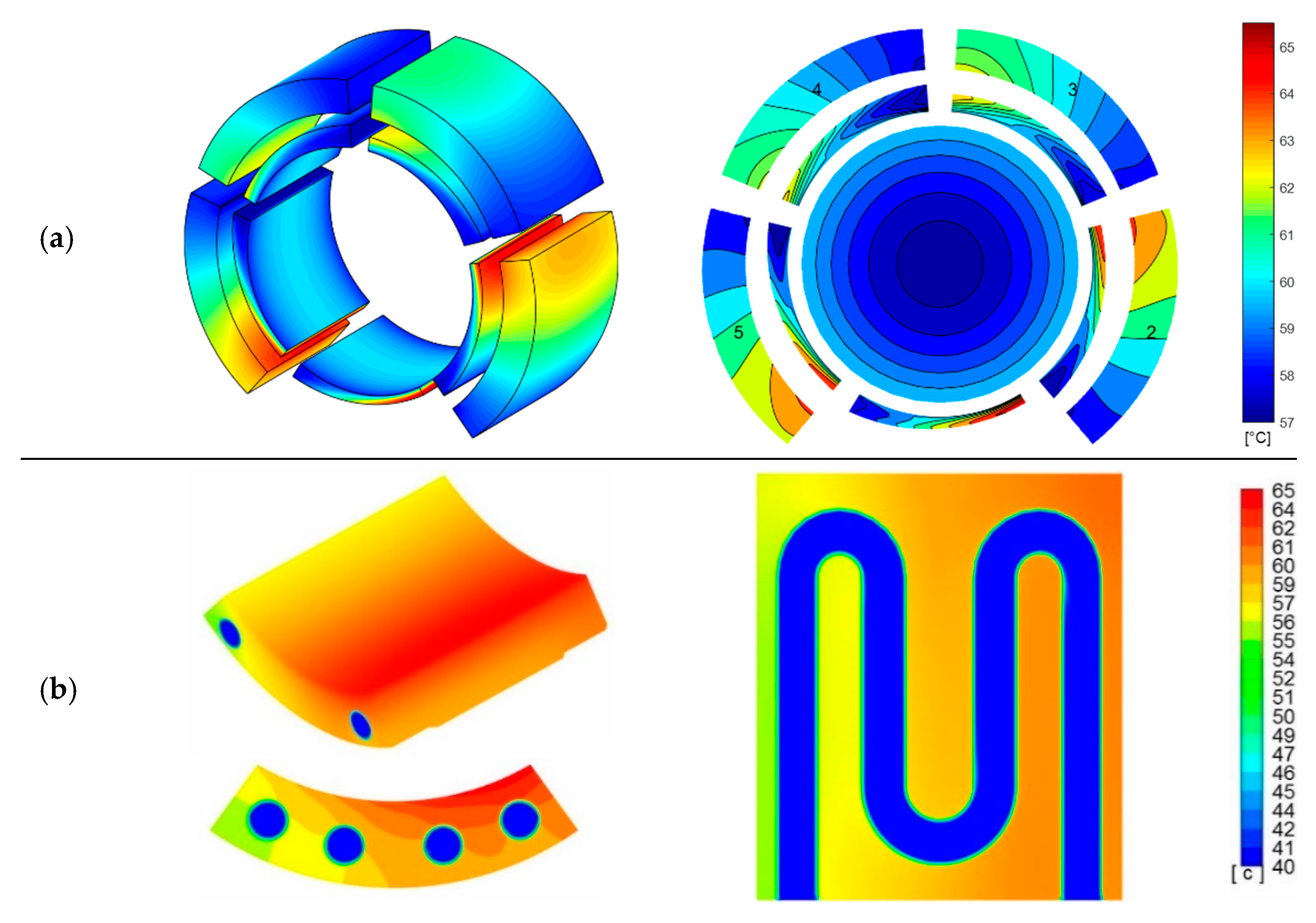
For the sake of brevity, the temperature distributions for the solid case (all pads without a cooling circuit), the cooled pad C1 case (circular cross-section) and the cooled pad S1 case (6-square cross-section) are shown in
Figure 16,
Figure 17 and
Figure 18, respectively. Subfigures (a) were obtained via MATLAB models, whereas subfigures (b) were obtained by Fluent models.
The following considerations can be extracted by the analysis of the results and temperature distributions:
The cross-section shape of the circuit has a great influence on the heat exchanges. As expected, the multi-channel solution (6 squares) is the most effective because it allows the increase of the heat exchange surface and, therefore, the reduction of the maximum temperature in the bearing.
Obviously, a lower inlet temperature of the cooling fluid decreases the temperature in the cooled oil-film.
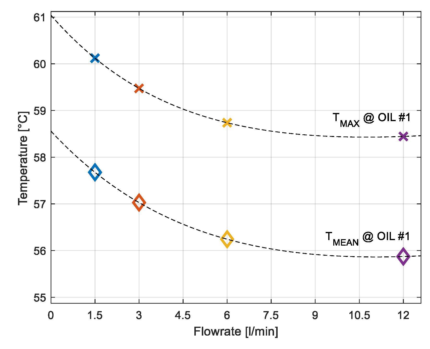
By assuming the same inlet temperature condition of the cooling fluid, better results (lower pad temperature) are obtained if water or more suitable cooling fluids are used. The higher specific heat of water allows for very efficient cooling. The main drawback is represented by the risk of leakage from the cooling circuit and the possible contamination of the lubrication fluid. The maximum and the mean temperatures in the oil-film of the loaded pad #1 are shown in
Figure 19 as a function of the corresponding water flowrates. It can be seen in
Figure 19 that beyond a certain flowrate value (approximately 6 L/min), the temperature cannot be further reduced.
The core temperature of the cooling fluid remains more or less constant along the circuit path in the cooled pad for the cases with flowrate higher than 6 L/min. This finding explains the low influence of the cooling flow direction (
Figure 13) on the overall mean temperature of the bearing in the investigations of cases S4 and S9.
By cooling the loaded pad (pad #1) only, the temperature of the cooled pad and that of the subsequent pads can be reduced. The increase in the number of cooled pads allows the maximum reduction of temperature to be obtained.
The cooling effect is more evident in the case of heavy operating conditions. For example, the values of the maximum temperatures of pad #1 and the temperature at the tip of temperature probe are shown in
Figure 20a as a function of the rotational speed (3000 rpm, 6000 rpm and 10,000 rpm) for the solid pad case and the cooled pad S2 case (6-square cross-section). Laminar flow has been assumed in this analysis. The results at 3000 rpm correspond to the solid and S2 cases listed in
Table 5 and
Table 6. In
Figure 20b, it is possible to observe that the reduction of the temperature of the cooled pad (maximum and probe temperatures) with respect to the solid pad is greater at high rotational speeds as shown in
Figure 20b.
5. Experimental Tests
Simple experimental tests were performed by means of the test rig of the Department of Mechanical Engineering of Politecnico di Milano widely described in [
22] and [
29]. Some pictures of the experimental setup are shown in
Figure 23. The test rig is mainly composed of a rotating shaft supported by two five-pad TPJBs (Eurobearings S.r.l. Cortemaggiore (PC), Italy) with the same geometries, placed at the NDE and DE sides. The rotor is driven by a 6-kW inverter-driven asynchronous electric motor (ABB S.p.a., Vittuone, Italy) by means of a flexible coupling (KTR Systems Gmbh, Bologna, Italy) up to the maximum rotational speed of 3000 rpm. Each bearing housing is connected to the machine frame by two orthogonal 20 kN load cells (HBM Italia s.r.l., Milan, Italy). The load is applied in the middle of the shaft by means of two hydraulic actuators (Studio AIP, Oggiona S. Stefano, Italy) through two rolling element bearings.
A dedicated hydraulic unit for the ISO-VG 46 cooling oil (Exxon Mobil Corporation, Roma, Italy) (the same as that used for the lubrication process) was used for the cooling circuit equipped with a volumetric pump and a dial flowmeter. Simple flexible rubber hoses for low pressure oils have been used for connecting cooling circuit of the pad to the hydraulic unit allowing no restrictions in the tilt of the pad. The oil temperature entering the circuit of the cooled pad is controlled by a closed loop acting on the fan of the oil cooler and the thermal resistance in the 100-litre oil tank. Temperature and pressure probes are also installed close to the bearings for monitoring the inlet and outlet cooling oil.
The solid pad obtained by the additive manufacturing process is placed in the loaded direction of the TPJB in the DE side, whereas each of the two cooled pads (circular and 6-square) was installed in the loaded direction of the TPJB in the NDE side. All other pads in the two TPJBs have the same geometry as those under test and are obtained with a standard manufacturing process. The loaded pad in each bearing is equipped with a temperature probe. In this way, a direct comparison of the thermal behaviour of the cooled pad provided by the temperature probe (temperature ) with respect to that of the solid one (temperature ) can be performed.
The tests have been performed with a fixed vertical load on each bearing equal to 5 kN, inlet lubricant temperature () at 40 ± 1.5 °C, and inlet cooling temperature () at 30 ± 0.5 °C. The tests were performed by (i) starting from a steady-state condition with closed flow valve (no cooling effect), (ii) opening the valve and changing the cooling flowrate at constant speed, and (iii) changing the shaft speed at fixed flowrate.
The three values of cooling flowrate have been considered by acting on a flow valve and estimating the flowrate by a flowmeter. The test was performed by considering the following flowrates: maximum flow (5 L/min), mid-flow (2 L/min) and closed valve (0 L/min). The three shaft speeds (Ω) are 2300, 1700 and 1100 rpm. For technical issue it was not possible to run the shaft at same rotational speed considered in the simulations (3000 rpm).
The experimental temperatures for the circular and the 6-square cooled pad are shown in
Figure 24 and
Figure 25, respectively.
represents the difference of temperature between the two loaded pads,
for the solid pad in the DE side and
for the cooled pad in the NDE side. It must be noted that the value of the inlet temperature of the cooling fluid
is unnecessary when the cooling circuit is switched off.
The timeline is divided into six regime phases, where the thicker lines in the plots represent the average values over the time span of each phase:
Ω = 2300 rpm steady-state condition; cooling circuit switched off. The behaviours of the solid and cooled pads are the same, as shown by the negligible value of the temperature difference . It is possible to observe the long-time oscillation with a period of approximately 20–25 min in the lubricant supplied temperature due to its temperature controller, as also highlighted by the oscillations in the pad temperatures and . Short-time and low amplitude oscillation due to the controller of the cooling oil temperature can also be noticed in the cooling oil temperature in the experiments.
Ω = 2300 rpm; cooling circuit switched on with fully open valve (5 L/min). The temperature
is influenced also by the oscillations in the inlet temperature of the cooling fluid
, and it is drastically reduced with respect to that of the solid pad. In this phase, the maximum reduction of the pad temperature in the cooled pad can be detected: approximately 11 °C for the 6-square case (
Figure 25) and approximately 6 °C for the circular cross-section (
Figure 24).
Ω = 2300 rpm cooling circuit; mid-open valve (2 L/min). sensibly decreases by approximately 6 °C for the 6-square and 5 °C for the circular case. Between phases III and IV, the flow valve is closed and then completely opened again.
Same conditions as for phase II. For this phase, the valve is kept open to investigate only the effect of the speed variation.
Ω = 1700 rpm; cooling circuit with fully open valve (5 L/min). Both and decrease, as does their difference: approximately 9 °C for the 6-square and 5 °C for the circular case.
Ω = 1100 rpm, cooling circuit with fully open valve (5 L/min). A further decrease of , and can be observed (approximately 7 °C for the 6-square and 4 °C for the circular pad).
In
Figure 24 and
Figure 25, the thermal inertia of the system is clearly visible, especially in phases I, II and III; for this reason, the average values in the interval are also plotted as a straight line.
In
Figure 24 and
Figure 25, the expected temperatures at the temperature probes are drawn with dashed lines for the solid bearing and the 6-square cooled bearing.
The hot clearance profile of the real bearing was evaluated by experimental tests, as already investigated by the authors in [
22,
23]. The estimated assembled clearance of 52 µm, which is less than the nominal value listed in
Table 1, has been assumed in the simulations for the estimation of the temperatures in
Figure 24 and
Figure 25. It should be noted that the expected temperature values are lower than the real ones, probably due to other effects not considered in the simulations such as the deformations of the pads and the thermal expansion of the shaft. However, it is possible to highlight a good agreement between the forecasts and the measurements of the temperature difference
between the solid and the cooled pad (see also
Figure 26).
A further comparison between the two cooled pads in terms of temperature reduction
with respect to the solid pad for the six operating conditions is shown in
Figure 26, in which the better cooling effectiveness of the 6-square at maximum speed and maximum cooling flowrate can be highlighted.
The temperature measured by the temperature probe of pad #1 for the solid pad installed at the DE side of the test rig (
) is about 65–67 °C at 2300 rpm (phases I, II, III and IV), for the circular cross-section (
Figure 24) and the 6-square case (
Figure 25).
6. Conclusions
In this paper, the reduction of the temperature in a tilting-pad journal bearing equipped with cooled pads has been investigated by means of numerical simulation based on CFD analysis.
The static and dynamic behaviours of two cooled pads with different cooling circuit cross-sectional geometries have been compared to the behaviour of a reference bearing equipped with all solid pads. From the simulation, the main results are as follows:
the multi-channel cross-section is better than the single channel configuration in terms of temperature reduction. The modern additive manufacturing technology can be exploited for the design of high heat exchange cross-sectional shapes;
a more suitable cooling fluid than the oil used in the lubrication process is preferable;
a limit in the cooling flowrate exists, beyond which the temperature cannot be further reduced;
good temperature reduction can be obtained by equipping the bearing with at least one cooled pad in the direction of the load; and
negligible differences have been highlighted in the investigation of the flow direction.
The simple experimental tests shown the feasibility and the effectiveness of the solution, allowing a maximum reduction of approximately 11 °C (in the middle of the pad) for the 6-square cooled pad with respect to the solid pad.
The manufacturing cost of each pad has been estimated as 20% higher than standard pad. The cost of the external cooling system can be reduced if the same supply system of the lubricating oil is also used for cooling the pads. The highest benefit can be obtained for large TPJB operating at high temperature.
The reduction of the bearing temperature can have several benefits, among them the increase of the operating speed and load or conversely the reduction of the bearing dimension and the reduction of thermal creep issue that sometimes occurred in large TPJB.


