1. Introduction
Eco-friendly technologies represent a positive trend for the future. The achievement of ambitious goals in terms of energy savings is strictly related to the capability to design more efficient systems.
In these regards, the recent developments in computer science have opened new possibilities. While in the past, different design solutions were characterized from an energetic point of view by means of experimental tests, in recent years more and more numerical studies are available in literature. Numerical techniques, in fact, allow to overcome the need of prototyping, enabling a comparison and an optimization of the different designs starting from the earliest stages of the development.
With focus on the efficiency and thermal behavior, CFD (computational fluid dynamic) seems to be one of the most appropriate tools to study churning losses of mechanical components, including bearings. Among the different CFD-approaches, SPH (smooth particle hydrodynamic), a meshless method, has the advantage of being easily applicable [
1] even if the accuracy of the results was shown to be insufficient for comparable computational effort [
2]. On the other side, mesh-based methods such as FV (finite volume) allow very high accuracy but in most cases the computational effort required is not compatible with the industrial practice [
3]. To partially overcome this problem, in the past several attempts were made. In particular, rotating reference frames [
4,
5], innovative partitioning strategies [
6,
7] and, mostly, mesh-handling algorithms [
8,
9,
10,
11] have been developed and applied in order to reduce the simulation effort.
Among the mesh-based methods, most approaches require geometrical, kinematical or physical simplifications.
Simple numerical studies dealing with single rolling elements (e.g., as spheres) or neglecting the relative motion between the elements were published by Noda et al. [
12], Gonda et al. [
13], Gao et al. [
14,
15] and Marchesse et al. [
16].
Hu et al. [
17] studied the oil distribution and the power losses of a bearing by means of commercial software using a rigid mesh motion/mesh sliding strategy. This approach relies on multiple meshing regions with interfaces between the grids. A similar approach was used by Zhang et al. [
18]. Liebrecht et al. [
19,
20] used the same modelling technique to study tapered roller bearings.
Rigid mesh motion/mesh sliding strategies have also been implemented in open source software. Examples of application of those strategies to bearing simulations were reported by Felderman et al. [
21]. This approach is effective, but the presence of interfaces introduces numerical interpolation errors and, most importantly, affects the computational effort by introducing additional equations to be solved.
Steady-state approaches relying on rotating reference frames were used by several authors. Among them, Raju et al. [
22] who studied needle bearings, Adeniyi et al. [
23] who studied aeronautical bearings and Wen et al. [
24] who simulated ball bearings. These approaches could be effective for rotating elements. However, this approach is not capable to reproduce the roto-translational motion of the rolling elements could not be reproduced.
Among the different approaches, the rigid mesh motion/mesh sliding strategy seem the most appropriate to simulate bearings, because it allows the proper reproduction of the geometry and the kinematics without simplification. In this paper, thanks to self-developed boundary conditions, the rigid motion of all the bodies was set without the need of interfaces between multiple grids, i.e., limiting the number of equations to be solved. Moreover, considering that the final goal of the research is to study and optimize the lubrication and the efficiency of roller bearings (this requires a plenty of simulations), a first stage was dedicated to the study of how several levels of geometrical simplifications could affect both the physical results and the computational efficiency. Among the studied simplifications were rounding radii and symmetries (this implies neglecting gravity). The most effective and computationally efficient model will be selected for the successive lubrication studies. For each model, an ad-hoc meshing strategy was developed and implemented in the OpenFOAM® environment. Limiting the computational effort by avoiding any kind of mesh deformation and need for remeshing, together with an analytical control of the mesh generation to better handle the element distribution and quality parameters, is fundamental for the successive stage in which the most appropriate model will be used systematically to study and optimize the lubrication and the power losses of a bearing. Only having effective and computationally efficient models will make it possible to perform systematical studies. This paper is intended to show the capabilities and performance of the different approaches for this kind of investigation.
2. Materials and Methods
2.1. Bearing Losses
Bearings allow the relative rotation between two mechanical components.
In journal or hydrodynamic bearings, the converging gap ensures that the two surfaces are kept separated by a fluid flow which implies frictional losses. The power dissipation is mainly due to viscous effects. This kind of bearing was already studied in the past by the author using OpenFOAM
® [
25]. This kind of simulation is relatively simple from a geometrical point of view because the domain does not significantly change its shape during operation.
Rolling bearings are geometrically more complicated and carry the load by means of interposed rolling elements.
The load independent power losses of rolling bearings can be classified into seal losses and hydraulic losses. The latter can be further subdivided into squeezing and churning/windage ones.
Squeezing losses are mainly related to volume variations and pressure gradients that causes additional flows. Churning losses are due to the splashing of the lubricant due to the motion of the components. It is well known that the squeezing losses, except for spray lubrication, are of a lower order of magnitude with respect to the churning ones [
26].
The focus of this paper is on the churning losses. Thus the EHL film was neglected, as it is standard practice [
27,
28,
29,
30,
31] to adopt different numerical methods for it. Therefore, also the modeled gap between rollers and races is not fully representative of the real one and each bearing element is in its nominal position. The rollers move around the bearing and rotate around their axis, but maintain their relative position in the center of the cage-pocket and the middle of the races. Moreover, the gap between rollers and races was increased to 0.05 mm. With these assumptions, changes in the rheology of the lubricant and the entire EHL regime, can be neglected. This assumption is standard practice when studying the churning losses of bearings. The goal is to separate the churning losses from the contact losses, which are commonly calculated using special EHL tools and are not the focus of this study.
2.2. Bearing Geometry
The bearing considered in this study is a Schaeffler NU222-E-XL-M1 with a roller guided cage and NU222-E-XL-M1A (
Figure 1) with an outer ring guided cage (for the purposes of this study, the main difference between the cages is the width of the radial gap between the cage itself and the shoulder of the outer ring—
Figure 2). It is a cylindrical roller bearing whose dimensions are listed in
Table 1.
This model of a non-locating bearing with a single row of cylindrical elements has a very high radial load carrying capacity and is suitable for higher speeds compared to full complement designs. The rollers are axially guided between rigid ribs in the outer ring. The cage has a solid design and is made of brass. The radial clearance between rollers and cage is 90 μm.
In the studied configuration, the lubricant was supplied radially into the space in front of the bearing. The inner ring was rotating with a speed of 4500 rpm (slightly below the limiting speed nG) while the outer ring was stationary. Consequently, the rotational speed of the cage resulted in 1904 rpm and the rotational velocity of the rollers around their own axis in the inertial frame results was 14,300 rpm. The lubricant selected for this study was an ISO VG 320 which has, at the simulation temperature of 95 °C, a kinematic viscosity of 27.9 cSt (mm²/s). The density resulted in 880 kg/m3. The oil flow on the inlet was set to 4 l/min for the complete bearing.
2.3. Simplifications
The abovementioned bearing model was considered in the study. However, several levels of simplifications were introduced and studied: presence or absence of the outer ring ribs and rounding radii, sectorial symmetry (not capable to consider the effect of the gravity). Furthermore, 2 different cages were analyzed.
Table 2 shows the full list of the simulations performed. In simulations #1 to #3, just 1 sector of the bearing (360°/17) was modelled. This was possible thanks to the cyclic symmetry of the system. The study of the effect of the different simplifications was aimed to create a numerical model whose solution requires a limited computational effort.
2.4. Meshing Strategies
The different configurations have different internal geometries. While the main differences in the topology are due to the presence of the ribs and the cage model, from a meshing point of view, the rounding radii are the most critical parameter to be handled. For this reason, different approaches were used. All the tools used for meshing are included in OpenFOAM®. However, the different approaches could be coupled together and applied to bearings only with the development of meshing templates specifically suited for such configurations.
2.4.1. Analytical Meshing & Interfaces
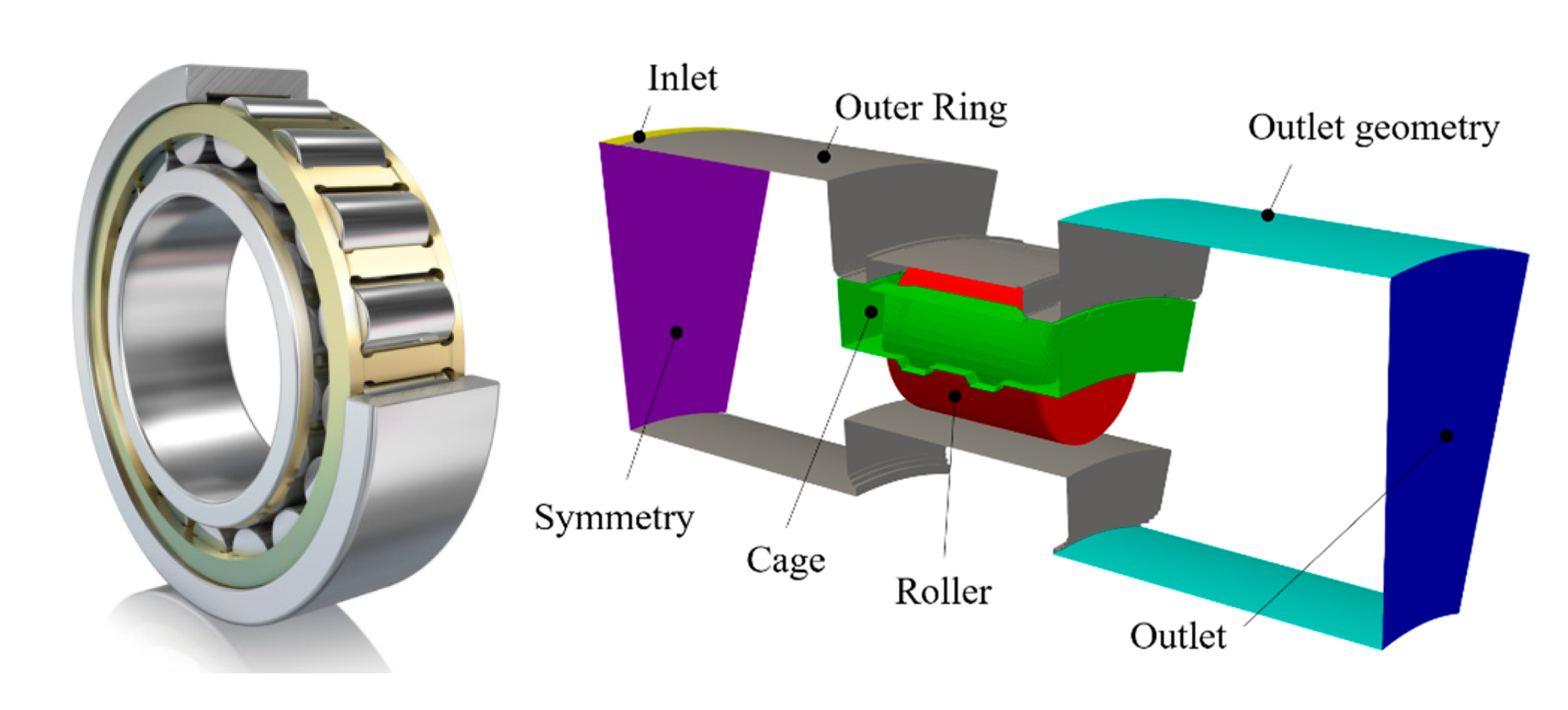
The approach we called “analytical meshing & interfaces” was used for simulation #1. A first subdivision of the domain was made axially between the rolling element end faces and the internal faces of the cage (whose surface normal is parallel to the bearing axis). A second subdivision was made just after the opposite face of the cage. This was done both for the inlet, as well as for the outlet side (purple surfaces in
Figure 3). This ensured that a mesh with extruded prismatic elements only was created for each axial portion of the domain. The 5 meshes, belonging to the different axial slices of the bearing, result conformal among them from a geometrical point of view, but not conformal in terms of position of the nodes. The introduction of arbitrary mesh interfaces (AMIs) [
32] allowed the numerical connection between those meshes. The AMI operated by projecting one of the patches boundary mesh onto the other, ensuring that that the values of a generic field were the same on both sides of the interface.
The principle behind this approach was the decomposition of one lateral face into a set of quadrilaterals. Edges can be straight lines, arcs or splines [
33]. The further discretization of the 4-edged polyhedron was defined through the seed of 2 adjacent edges. In
Figure 3 (bottom left) it can be appreciated that the grid—created with blockMesh [
32]—was made of 19 quadrilaterals (blocks). The blocks always had 4 edges. Some of them were curved according to a defined function. In block 2 (1st mesh), for example, the upper edge was curved to follow the outer ring curvature. The left edge of block 8 (1st mesh), was curved to follow the curvature of the roller. Other edges (for example of block 10—1st mesh) were curved just to keep the quality of the elements above a certain threshold.
The 2nd (and 4th) portion of mesh between the 1st and 2nd AMI (3rd and 4th AMI) (bottom center of
Figure 3) was made of 6 blocks. The central mesh between the 2nd and 3rd AMIs (bottom right of
Figure 3) was made of 15 blocks. The possibility to create the mesh as a compound of multiple blocks allowed better control of the internal quality of the grid and significantly sped up its generation. The creation of this grid (1.2 M cells) had taken, on a 48 GFLOPS workstation, only 8 s. The finest grid used during the mesh sensitivity analysis with the same block layout, was of about 7.3 M cells. Its generation takes about 55 s showing a linear scalability.
2.4.2. Analytical Meshing without Interfaces
For configuration #2, in which the rounding radii were neglected (but not the ribs), it was possible to create the whole geometry with multiple extrusions without the need of AMIs. To achieve this goal, a more complex partition of the frontal (extrusion) surface (
Figure 4 left) was used. This consisted of 39 blocks. Not all the blocks were extruded for the whole bearing length. Block 1 to 5, for example, were missing in the mid (axial) portion where the outer ring was located. In the same way, blocks 11, 13, 18, 22, 23, 24, 27, 28, 29 and 39 were not extruded in correspondence of the roller. This approach was very powerful and enables the creation of a good quality grid in a very short time (10 s). However, with this approach, it was not possible to model all the rounding radii like those of the rings and of the roller.
2.4.3. Analytical & Subtractive Meshing Approach
In order to simulate configuration #3, in which all the rounding radii were modelled, a first mesh, without internal cavities (like those corresponding to the roller and the cage for simulation #2) was created analytically with 39 blocks successively extruded. This initial background grid generated (
Figure 5 up left) in 11 s. Differently from mesh #2, the 39 quadrangles of the plane surface (
Figure 4 right) where extruded for the whole axial length of the model. Successively, in order to create the boundaries corresponding to roller, cage and rings, a cut of the background mesh using a subtractive approach (snappyHexMesh [
32]) was used. In a first stage, the cells of the grid intersecting the surfaces of roller, rings and cage (defined via .stl files), were split into smaller cells (refinement). Each cell was subdivided into 8 smaller cells. Eventually, if required, the resulting refined cells were further split until the desired accuracy is reached. Once this operation is complete, a process of cell removal began (
Figure 6). All cells inside the stl-defined boundaries (i.e., inside the solid rollers, the solid cage and the solid rings) were removed from the grid.
This approach was very effective but not as efficient as the analytical generation. The conversion of the background grid into the final mesh took about 75 s. This was, in any case, still a much better result with respect to a comparable automatic tetrahedralization which took, using a Netgen [
34] algorithm, about 900 s.
Table 3 summarizes the properties of the meshes obtained with the different approaches (the geometrical configurations are described in
Table 2). The number of cells reduced from configuration #1 to #2 due to the presence, in the latter one, of the ribs that limit the volume of the computational domain. Mesh #3 had the highest number of cells because, to accurately follow the rounding radii, the above described mesh splitting step produced a much finer grid near the boundaries. This was confirmed by a higher number of faces of the grid of configuration #3 that, except for the rounding radii, was very similar to configuration #2.
The meshes reported in
Table 3 are, for each method, the best compromise between accuracy and computational effort. A mesh sensitivity analysis was performed. As a matter of example, for configuration #1 meshes having between about 0.5 M and 7.3 M elements were created and simulated. Even with the finest grid, the result in terms of power losses differs from the actual one (1.2 M elements) by less than 1%.
2.4.4. Full Model
To understand the effect of gravity (which relative orientation is a function of the bearing sector position) on the oil flow through and oil distribution in the bearing, a simulation of the full geometry was also performed (
Figure 7). For the rotational speed considered, no significant differences in terms of losses and lubricant distribution were expected with respect to the sectorial model because centrifugal effects are dominant. Nevertheless, to have a complete understanding of the physical phenomena, it was fundamental to investigate also this effect.
To build the full grid, a circular pattern of the sectorial mesh #3 was made. The different meshes were conformal and could be easily stitched together. Therefore, the number of cells of the #4 grid results was 17 (number of rollers) times larger than mesh #3.
2.5. Boundary Conditions and Mesh Motion
A two-phase incompressible, isothermal solver for immiscible fluids was used. It was based on a VOF (volume of fluid) phase-fraction interface capturing approach. In such applications, in fact, the air flows were as important as the lubricant one and a single-phase simplification was not acceptable. A rigid mesh motion without topology changes or adaptive re-meshing was imposed to simulate the motion of the components. The rotational speed of the grid corresponded to the rotational speed of the cage (1904 rpm). This required the development of two boundary conditions (BC) to properly assign the rotational speed to the different components. Since the grid was rotating, the rotational speed of the rings were defined in the rotating reference frame by adding (inner ring) or subtracting (outer ring) the proper velocities. In the same way, the roto-translation of the rollers was obtained by adding a pure rotation to the motion of the grid.
Table 4 summarizes all of the BC.
Gravity was considered. Simulation were performed limiting the Courant (Co) number to 1 to ensure numerical stability and good convergence. The Co is a measure of how fast information traverses (u) a computational grid cell (∆x) in a given time-step (∆t). The solution of the system was performed with a PIMPLE (merged PISO-SIMPLE) algorithm. This conjugated the advantages in terms of computational efficiency of the SIMPLE scheme with the capability of the PISO one to be time-conservative [
32].
Mass, momentum and volume fraction conservation equations were defined as follows:
where
is the density,
is the velocity vector,
is the kinematic viscosity of the lubricant,
is the gravitational acceleration and
represents the external forces.
is a scalar that represents the volume fraction of the one of the two phases in each computational cell. The averaged properties (
) of the mixture in each cell of the domain are calculated as an
-averaged value of the properties of air and lubricant.
3. Results
The main goal of the project was to study the effects of the geometrical simplifications on the lubricant distribution and the power losses. The sectorial simulations were performed on the VSC cluster [
35] while the full simulation (#4) on a Deploy Linux LXD [
36] Compute Node [
37] backed by a Ceph storage cluster [
38].
Table 5 summarizes the properties of the computational nodes.
Figure 8 shows the predicted power losses of the different configurations. Losses included viscous and inertial effects and were computed from the shear stresses and pressure fields on each boundary element.
To validate the numerical results, two empirical models were used for comparison. The first one, proposed by Harris [
39], is based on experiments. For the current configuration, it predicts 630 W (churning losses only), slightly below the numerical results. The second approach uses the software B
earinx [
40,
41]
. With this approach, the predicted churning losses were 737 W. While the predicted values were comparable to the experimentally derived ones, the CFD results enabled a better understanding of the physics behind the phenomenon and how different geometries and parameters are related to different levels of loss.
Despite the different geometries, mostly between #1 and #2 (ribs), the power losses were comparable. However, it is opinion of the authors that these results cannot be generalized to different rotational speeds. The rounding radii seemed to not significantly affect the power dissipation. It could be observed that the regime condition (stabilization of the losses) was reached much faster in the simulation #1. The absence of ribs, in fact, promoted an easier lubricant flow in the axial direction.
While simplification #1 seems to significantly modify the physical problem producing meaningless results,
Figure 9 shows the effect of the rounding radii. On the left-hand side configuration #2 is shown. The absence of the rounding radii on the external race caused a stagnation of the lubricant and a higher wetting of the outer radial surface of the cage. This impacted also on the wetting of the radial surface of the roller that resulted in less lubrication in configuration #3.
Figure 10 highlights the differences induced by the relative position to the roller with respect to the gravitational acceleration. Small differences in terms of oil distribution were present even if the structure of the bearing was axis-symmetric and the mesh was the same for each sector. As can be expected, the lower the position of the roller, the higher its wetting with lubricant.
Even if the results shown in
Figure 9 refer to a specific time step (instantaneous flow field), they were selected to be representative of the regime condition showing the averaged effects of the presence of rounding radii on the oil flows.
Computational Effort and Scalability
The 7.3 M- and the 1.2 M-cells meshes (configuration #1) were used to assess the scalability of the numerical model on the number of processors. For the finer grid, simulations were performed on the VSC cluster using 64, 128 and 256 cores.
Figure 11 (left) shows the good scalability of the results. The same was made for the 1.2 M mesh. While the scalability seemed to be linear up to 64 cores, the time required for the solution did not reduce significantly with 128 cores. With 256 cores, the computational effort even increased. This was due to the time required for the exchange of information between processors that became higher than the solution time itself. The best configuration for this specific case was found to be around 20 k cells per core.
4. Conclusions
OpenFoam® 4.1 with some specifically developed boundary conditions seemed to be suitable for lubrication simulations. A Schaeffler NU222-E-XL-M1 bearing was modelled with hexahedral elements taking advantage of different meshing strategies. The studied geometrical simplifications seemed to not significantly affect the power losses, but unquestionably affected the lubricant distribution and lubrication of the different components. The presence of the rounding radii on the outer ring promoted the lubricant circulation reducing its stagnation between cage and rings. The components result was less wetted.
Gravity seems to slightly affect the wetting of the rollers—depending on their position along the circumference of the bearing—but these results cannot be generalized to different speeds.
The proposed meshing approaches enabled different levels of geometrical complexity. Each meshing strategy started from the extrusion of a structured grid. The capability to create a 3D grid starting from a simple extrusion allowed a much better control of the mesh quality that directly affected the convergence of the solution and, therefore, the computational effort required. The reference grid (7.3 M cells) generated in about 55 s with the “analytical meshing & interfaces” approach. Despite the good meshing performance (a comparable tetrahedral mesh generates in 900 s), the presence of interfaces slow-down the solution due to the additional equations to be solved. The “analytical & subtractive meshing approach” was less computationally efficient (75 s for the creation of the mesh) but did not affect the simulation time. The “analytical meshing without interfaces” was the most computationally efficient in the creation of the grid (10 s) and did not affect the simulation time. However, it was restricted to simple geometries.
Scalability tests indicated, for two different grids, that an average number of cells per core of about 20 k was the best balance between computational resources and computational effort (on the present hardware).


