Equal-Channel Angular Extrusion (ECAE): From a Laboratory Curiosity to an Industrial Technology

Engineering Performance Materials (EPM), 11228 Lemen Rd, Suite A, Whitmore Lake, MI 48189, USA
Metals 2020, 10(2), 244; https://doi.org/10.3390/met10020244
Submission received: 6 January 2020
/
Revised: 1 February 2020
/
Accepted: 9 February 2020
/
Published: 12 February 2020
Abstract
:This paper presents a state-of-the-art and a retrospective view of the critical stages in the evolution of equal-channel angular extrusion (ECAE) from the original idea to a cost-effective industrial technology. These stages include optimization of the structure modification and material processing, development of the special tools, process commercialization, and a large-scale validation of the semi-continuous ECAE at the industrial floor. All aspects are extensively summarized, based on the author’s experience in the field, which spans almost half of a century. Special attention is paid to the processing of large batch billets. Practical examples illustrate industrial applications of ECAE. The scope for future development is also discussed.
1. Introduction
Severe plastic deformation (SPD) has attracted a significant interest in materials science since the 1980s. As a scientific concept, SPD was generated by the work of Bridgman on high-pressure physics in 1930–1950 [1]. His primary interest was in phase transformations under extremely large pressures, temperatures, and shear strains occurring in the Earth’s mantle during the formation of ores, gems, and other minerals. Bridgman introduced a technique of compression with rotation between the anvils, which was very successful in imitating complex physical and geological processes. Using a combination of “high-pressure + shear”, he made numerous discoveries. In particular, a dramatic refinement of grain structures in metals to the nano scale was first described in [2]. Finally, his pioneering work led to a synthesis of diamonds and, subsequently, to the Nobel Prize (1946). Although the technique of Bridgman’s anvils, known as high-pressure torsion (HPT), can be applied only to small thin discs, it has remained a powerful tool in many modern studies. However, because of specific technical problems such as large torque/load and difficulties to scale up, research on HPT is a purely academic despite numerous reports on the property improvements of different materials.
To address this situation, alternative methods of SPD have had to be introduced, which could be considered, at least, as potentially industrial technologies. The first such approach was suggested by the author in 1972 [3]. The original aim was the optimization of SPD using translation shear instead of twist, and the development of a related processing technique as an effective metal-forming operation. After extensive theoretical and experimental research, equal-channel angular extrusion (or pressing) (ECAE/P), providing a near “ideal” simple shear deformation mode for structure modification and optimal technological characteristics, was introduced [4]. In contrast to HPT, this technique was identified as “simple shear processing” [5]. During subsequent development, ECAE was transformed from a laboratory tool into a full-scale industrial operation and became the first, and still unique, commercialized technique of SPD. It is noteworthy that HPT and ECAE established SPD as a scientific concept and as a material processing technology, respectively.
Later, other techniques of SPD were also suggested in numerous works overviewed in [6,7,8] and others. The total number of known techniques and their modifications now exceeds, probably, 100. These differ significantly in technical realization, products, and attained results. The published studies have demonstrated the different effects of the specific techniques on structure evolution depending on the intensity and distribution of shear strains. However, the comparison of their efficacies is complicated because related analyses of the processing mechanics are usually poor, and information on the technological characteristics is insufficient or missing. From this point of view, all known techniques of SPD may be classified by mechanisms of inducing simple shear based on a few fundamental ideas [4]:
- Surface simple shear developed by contact friction (HPT, high-pressure tube twisting, cone-cone method, etc.);
- Local surface straining by sliding, rolling or penetration (processes of surface SPD);
- Simple shear along the lines of velocity discontinuities in ordinary forming operations (multi-directional forging, cyclic extrusion-compression, repetitive forward/backward extrusion, etc.);
- Simple shear between areas of strong flow inhomogeneity (known as “simple shear” and “pure shear” extrusions, equal-channel forward extrusion);
- Internal simple shear induced by successive shifting or twisting through the complete material volume (ECAE, twist-extrusion).
This classification presents an opportunity for the comparison of specific techniques in terms of general mechanical characteristics. Techniques of contact friction [9,10] provide intensive and uniform simple shear in thin material volumes but cannot be transferred through large cross-sections. They require maximum friction as well as high loads, torque moments, and plastic work, and are difficult to scale up. Techniques of local surface straining [11,12] are effective for surface SPD as local incremental loading requires low forces and provides good accuracy and surface finish. Despite relatively slow processing, they are practically used in several applications such as surface burnishing by balls or rolls, high energy shot blast, etc. For bulk products, ordinary forming operations (multi-directional forging [13], cyclic extrusion-compression [14], etc.) are an attractive alternative because of the possibility to use existing equipment, experience, and engineering developments accumulated in the industry. However, insuperable technical problems are significant stress/strain inhomogeneity, change the deformation mode from simple shear to pure shear, numerous processing steps, and large stresses and loads necessary for severe straining at low temperatures. The same is true for recently suggested techniques of SPD based on intensive shear between areas of strong flow inhomogeneity [15,16], especially for hard materials and large-scale products. For internal shear by twist-extrusion [17], the deformation mode is approximately simple shear, but strain distribution is highly non-uniform and does not modify the materials in central areas. In contrast to all these techniques, ECAE, under controllable conditions, results in simple shear deformation mode with homogeneous strain distribution and optimal processing characteristics [3,18].
For practical applications, the biggest interest is the evaluation and comparison of various SPD techniques as industrial technologies. Information on new techniques is usually restricted by microstructural analyses and a single publication. Nevertheless, it is clear that many of these techniques are impractical. For example, techniques, in which billets are ejected from the tool by the following billets, are not suitable for the industry. In contrast, ECAE has been recognized as one of the most advanced and promising techniques of SPD. However, difficulties to scale up, low productivity, complicated tools, and high cost are often referenced as essential disadvantages. These shortcomings are not insurmountable and have been eliminated during systematic research and development focused on large-scale products and practical applications.
This paper presents a state-of-the-art and a retrospective view of the critical stages in the evolution of ECAE from an original idea to a cost-effective industrial technology. Based on the author’s experience, a comprehensive summary is provided regarding the optimization of structure modification and material processing, special tools, process commercialization, and large-scale validation at the production floor. As large products require a massive volume of the material, ECAE of large batch billets is considered in the paper. The scope of the future development is also discussed.
2. Mechanics of Simple Shear Processing
2.1. Ideal-Plastic Model of ECAE
Bridgman’s works demonstrated that material processing by intensive shear resulted in strong, and sometimes, unusual effects on structure and properties. The most perfect realization of this concept is simple shear deformation during plane plastic flow. Neglecting, as usual, the elastic strains and material hardening during SPD, a well-developed model of an ideal plastic material and the slip-line theory can be used for correct analysis of the processing mechanics as a function of the boundary conditions and tool geometry. This approach was first applied in 1970 for the synthesis of simple shear processing along two crossing slip lines AA and BB of a velocity discontinuity in “cross-extrusion” (Figure 1a) [3]. “Cross-extrusion” produces intensive mirror-like symmetric shears relative to the material mid-thickness a-a, but it cannot be considered to be an industrial operation. The same principle was further realized (1972) in equal-channel angular extrusion (ECAE) by simple shear along a single slip-line AO (Figure 1b). For steady and frictionless ECAE, simple shear along the straight slip-line AO is uniform, strictly oriented, and intensive depending on the intersection angle between channels. This “ideal” case is optimal for SPD processing. In real situations, there are additional conditions providing close approximation to the “ideal” case. They relate to the contact friction, tool design, angle of intersection between channels, and back pressure in the outlet channel.
2.2. Contact Friction
Despite the use of the best lubricants, some friction is always present during ECAE. The necessity to fulfill friction boundary conditions changes the plastic zone from the single slip-line AO (Figure 1a) to a central fan AOC (Figure 2a), the angle of which increases with the increase of friction. Figure 2a shows the slip-line field for equal friction in both channels [3,18]. The central fan AOC redistributes shears between three different directions and forms a “dead” metal zone ACD [3].
This zone prevents lubrication of the outlet channel with high normal pressure. Therefore, in reality, the friction in channels is different, and the slip-line field of Figure 2a should be modified [3]. With good lubricants, the coefficient of the plastic friction m is low in the inlet channel (m = 0.06–0.08) but may equal the maximum friction (m = 1.0) at the bottom wall of the outlet channel due to material sticking and galling to the tool.
In special cases of ECAE with movable channel walls, plastic friction may vary from maximum to zero, and may change sign from passive to active friction. The example of continuous ECAE with three characteristic friction zones along channel walls was considered in [19].
2.3. Channel Design
Originally, the principal idea of ECAE was extrusion without friction through two intersecting channels of the identical cross-sections. Subsequently, numerous modifications of the channel geometry were also suggested. These modifications transform the simple shear deformation mode and, therefore, are not beneficial both in terms of structure evolution and characteristics of processing. For example, channels frequently have radii R at the outside corner (Figure 2). For extrusion with friction, slip-line fields remain similar to that shown in Figure 2a, if the radius R is within the dead metal zone ACD. In alternate situations, including extrusion without friction, the slip-line field (Figure 2b) assumes a central fan AOD and an area of rigid rotation ADCB about a center O. Shear stresses along boundary BC may vary from zero to maximum. This case is especially deficient because of significant strain non-uniformity throughout the material cross-section [3].
2.4. Intersection Angle between Channels
It is known [5] that accumulated shear and extrusion pressure depend in the same proportion on the angle between channels [3]. This defines two criteria for the selection of the intersection angle. The intersection angle should be sufficiently large to increase accumulated shear; and additionally, it should be sufficiently small to reduce an extrusion pressure. The first case is restricted by forming of the “dead” metal zone ABC for angles less than 90° even in frictionless conditions (Figure 3a). A similar restriction for the second case is the transition from simple shear to material bending about the inner corner O (Figure.3b). Such plastic bending is an alternative deformation mode, when the bending moment M of all applied forces attains a critical value. This occurs with the increase of the intersecting angle between the channels or by the application of tensile force T to the extruded material. Practically, the intersecting angle should be less than 135°.
2.5. Secondary Effects.
The ideal-plastic analysis does not capture more complicated material behavior, which may be important in the specific cases. For low friction ECAE, the effects of elasticity, viscosity and plastic instability manifest themselves in (i) forming of so-called “gap” (Figure 4a), (ii) in small-scale localization (Figure 4b), and (iii) in a tendency for material rotation about the inside corner O after crossing the shear plane (Figure 4c). These secondary effects can present problems during multi-pass processing:
- (i)
- The “gap” (Figure 4a) between the material and tool at the outside channel corner A is usually observed after 1–2 passes and disappears with the increase of passes. It may lead to laps at the bottom billet surface. Applying moderate back pressure T in the outlet channel is an effective way to eliminate the “gap”;
- (ii)
- The small-scale localization at the bottom billet surface (Figure 4b) unveils and brings the atomically clean material in contact with the tool forming local centers of galling. Under high contact pressure and intensive sliding, local centers grow and finally lead to poor surface finish, large extrusion pressure, and low tool life. This can be avoided by eliminating sliding between the material and tool;
- (iii)
- The tendency for material rotation after crossing the shear plane (Figure 4c) is balanced by a reactive moment M in the outlet channel. This moment re-bends the material and develops tensile stresses in the vicinity of the channel corner O that leads to ductile fracture at the top billet surface. A small radius r of the inside channel corner removes a stress singularity around the sharp corner O, modifies stresses in this region from tensile to compression, and eliminates surface cracks [20].
3. Optimal ECAE Processing
Slip-line analyses unveil fine details and the optimal conditions of ECAE processing providing intensive and uniform simple shear, low extrusion load and stresses without surface cracks, laps, and other defects. These results can be summarized as:
- Contact friction should be as low as possible. It is important to lubricate billets and both channels before each pass.
- As billets in channels have a constant speed, tool walls moving with the same speed result in zero friction along related boundaries. This requirement is especially important for the bottom wall of the outlet channel.
- The optimal design comprises channels with a sharp outside corner and sufficient radii r at the inside corner. Additionally, the optimal design should apply automatically some back pressure during processing.
- The intersecting angle of 90° between channels provides the maximum shear strain per pass and results in acceptable extrusion stresses for most materials.
Additional requirements arise from the optimization of multi-pass processing. After each pass, billets should be fully ejected from the tool for lubrication and inspection of the billet and both channels. The ejected billets with correct size and shape without flashes can be immediately lubricated and inserted into the tool to perform the next pass. Such semi-continuous “pass-by-pass” ECAE eliminates the operations of billet cleaning, reshaping, and reheating, which are usually necessary for ordinary (or discontinuous) ECAE. “Billet-by-billet” extrusion, when billets are ejected by the subsequent billets, is especially deficient. In this case, after a few passes, the lubrication of the outlet channel is interrupted by progressive material sticking and galling, and correction of the billet shape is necessary after each pass. Such discontinuous processing is also unsuitable for industrial applications because of problems with either the ejection of the “last billet” or this billet being left in the tool for a short or long duration. In comparison with ordinary ECAE, semi-continuous ECAE dramatically reduces the processing time from hours to minutes.
In addition to the optimal characteristics of the processing mechanics, there are optimal processing conditions such as temperature, number of passes, extrusion speed, routes, back pressure, etc. The optimal processing conditions depend on the material, desired structure, properties, and area of application. The processing mechanics also shows a strong effect on these conditions. They should be fixed in each case of specific materials, SPD techniques, and tool design using experimental observations, structural analysis, and material testing. Therefore, the optimal processing conditions are highly variable and will not be considered here.
4. Evolution of the ECAE Tool
4.1. Early Development
In the beginning, the simple split dies, which comprised two round intersecting channels at an angle 90° were used. Billets of approximately the same cross-sections were extruded and ejected from the tool by subsequent billets. The first experiments on multi-pass processing of pure metals (copper C10100, aluminum alloy 1010, Armco-Iron) confirmed Bridgman’s concept of simple shear processing for the modification of structure and properties. New processing options, known as routes, were also discovered during this time [21,22]. These experiments proved that bulk ultrafine grained materials became a reality, and they could find practical applications. However, such simple tools did not show a practical potency. Extrusion required high stresses and loads, which exceeded theoretical estimations by 3 to 5 times; billet surface finish was poor with large material wastage and short tool life. Punch bifurcation, upsetting and fracture were also observed. This demonstrated clearly that tool design was the key factor for the ECAE technology. New ideas and approaches were necessary for further development of ECAE for applications to specific materials and technical problems.
4.2. Movable Channel Walls
In channels with rectangular cross-sections, some walls can be moved together with material. In this way, friction and galling along corresponding billet surfaces are completely eliminated. The first practical problem for development of such ECAE technique was the reprocessing of continuously cast steel billets into wrought stocks for forging of heavy track crankshaft [23,24]. A significant advantage of related technology was the full healing of large casting cavities and porosity in the central billet area after just one ECAE pass at hot temperatures without changing the material cross-section area. The project included a production line comprising a horizontal casting machine, a special ECAE press, and forging/trimming presses. For ECAE, the challenging problems were contact friction and large billet length-to-diameter ratio (up to 15).
These problems were resolved by the application of a movable slider (1) between two inlet (2) and outlet (3) channels (Figure 5a) and by using an effective graphite-liquid glass lubricant. This design is eliminated friction along three channel walls, provided punch strength and stability, balanced the slider, and delivered lubricant to the bottom walls of the outlet channels. After reaching the lowest position, the slider retreated and released the billets, which could be withdrawn from the outlet channels.
Another prospective area for the industrial applications of ECAE was the cold and warm processing of functional alloys for improving their special characteristic and mechanical properties. The critical conditions in this case were high extrusion stresses and material galling to the tool during multi-pass processing. This required a sophisticated combination of movable walls in both channels as shown in Figure 5b. Two sliders (1) in the inlet channel eliminated friction alongside the walls and provided punch strength and stability. A bottom slider (2) in the outlet channel substituted large plastic friction between material and tool with low friction between tool parts and eliminated sticking and galling. This design allowed processing of magnets, special elastic alloys, superconductors, and other materials with an ultimate tensile strength up to 1600 MPa. After completion of a working stroke, the bottom slider was moved to the limit left position by an additional cylinder, which fully released the billet ejected from the outlet channel by an additional punch stroke.
4.3. Plate Billets
In most cases of ECAE, there is a large mismatch between the simple geometric forms of rectangular or cylindrical billets and the complex shapes of most practical products, thus requiring additional post-processing, such as machining, or forming. ECAE of large plate-shaped billets with subsequent rolling was introduced for fabrication of plates and sheets of different thicknesses for numerous applications [22]. An analysis shows [3] that for plate billets movable side walls in the inlet channel are not effective but lead to complicated and expensive tools. The optimal design in this case includes only a plate slider 1 in the outlet channel (Figure 6). During extrusion, the slider is moved by a friction force F with the material. This force overcomes friction F1 between the slider and tool, which remains low if the extrusion pressure on the slider is uniformly distributed along the bottom slider surface. This condition is satisfied, if the ratio H/t > 2.5 where H is the slider thickness and t is the plate thickness. Billet ejection is performed similarly to Figure 4b. Because of simplicity and reliability, the plate tool attracts the most practical interest and has undergone the major development.
4.4. Large-Scale Tool
Another aspect of the practical promotion of ECAE is the large-scale tool. Many domains of suitable applications, such as automotive, aerospace and transportation, need advanced products of large sizes. Transition to the larger billets improves the technical and economical characteristics of processing. For a scale factor n = A/a, where A and a are identical large-scale and sub-scale dimensions, respectively, the billet weight, press load, extrusion stroke, and speed increase in proportion to n3, n2, and n, respectively. In this case, strain rates and extrusion times are equal for small and large bullets. Thus, large-scale processing provides a significant increase in productivity. Additionally, larger scale improves strain uniformity and reduces extrusion pressure due to more stable temperatures and friction conditions.
A design of the ECAE tool for large plate billets will be described below.
4.5. Continuous ECAE
There is significant interest in Conform–ECAE (C-ECAE) of long products, which are usually fabricated by rolling, drawing, or extrusion. The C-ECAE was first developed by the author in 1976 in Minsk, FTI, USSR [24]. The biggest problems present process instability, surface finish, and tool wear. In the ordinary Conform-extrusion, a length of the contact area between the material and tool is fixed. The material is first heated and, then, extruded by friction forces. Therefore, the stabilizing factor is a deviation in the extrusion temperature. For C-ECAE, intensive heating is not allowed. Slippage between materials and a roll and the increase of the processing temperature depend on the contact length. They are insignificant for the optimal length and increases with the increase of the length over the optimal value. For a length shorter than optimal, material skidding with intensive heating are observed [19]. The two later cases lead to overheating, tool wear, and interrupted processing. In the first design of C-ECAE [24], the contact length was adjustable by changing an eccentricity between the roll and ECAE tool. Nevertheless, extrusion was faltering because of variations in friction and processing conditions. The more advanced design of Figure 7 [19] provides a self-adjustment owing to the automatic change of the contact billet length Lb during processing.
4.6. Semi-Continuous ECAE (sc-ECAE)
The ordinary tool for plate billets (Figure 6) does not control their shape and size. Because of buckling at the front billet end and flashes at the top billet surface, the billet cannot be inserted in the tool in the next pass. Thus, additional operations of cooling, machining, cleaning, and preheating are necessary. The operational time per pass of such discontinuous processing comprises hours, especially for large billets.
A new concept of semi-continuous “pass-by-pass” ECAE without any additional operations was recently developed by Engineered Performance Materials (EPM) [25]. The schematic shown in Figure 8 illustrates the principle and tool design. The inlet channel 2 and the outlet channel 3 are formed by a tool block 1 and slider 5 mounted at a base plate 9. The slider has a protrusion 10 overlapping the outlet channel. In the original position, the billet 8 is inserted in the channel 2 and a hydraulic cylinder 7 moves the slider on the right till a tight contact is achieved between the billet and protrusion 10. During billet extrusion by a punch 6, the billet and slider in the outlet channel are moved with the same speed eliminating friction at the bottom billet surface and transforming friction between slider 5 and guide plate 9 in a back pressure. After completion of the stroke, the cylinder moves the slider to the limit left position, fully releases the billet, and the punch 6 pushes the billet onto the base plate. Then, the cylinder 7 returns the slider to the original position, ejects the billet from the die, and simultaneously cut off flashes at the top billet surface by a knife 11. As the billet in the outlet channel is fully constrained, it can be immediately lubricated and inserted into the inlet channel for the next pass.
This tool satisfies all requirements of optimal processing described in Section 3 and reduces the processing time per pass to a few minutes instead of hours.
5. First Commercialization of ECAE
In 1996, the patent on ECAE of plate billets [22] was licensed to Johnson Matthey Electronics (Spokane, WA, USA), later Honeywell International, Inc., for the fabrication of sputtering targets. This high-tech product is widely used for sputtering of thin films and has a significant impact on progress in electronics and semiconductor industries. Sputtering targets are massive plates with tendency to further increase. At moderate volume of production, there are strong requirements regarding finest grain size, texture, structure homogeneity and uniformity, strength and thermal stability. For interconnecting applications, sputtering targets are manufactured from Al, Cu, and their alloys, for whom a control of structures and properties is achieved through thermo-mechanical processing. However, ordinary forming operations such as forging and rolling cannot provide large shears necessary for structure refinement. Therefore, in terms of product, materials, and area of application, sputtering targets presented an excellent opportunity for commercialization of ECAE.
The first full-scale ECAE targets were obtained in 1997. An additional 3 years were necessary for their testing, evaluation, and certification by different electronics companies. The ECAE® sputtering product was introduced to the market in 2000. In comparison with existing counterparts, owing to refined and uniform microstructure, weak texture, and low number of second phases, ECAE targets demonstrated the superior properties such as film uniformity, step coverage, insignificant arcing, low number of particles, high strength, long target life, etc. A detailed description of the target performance can be found elsewhere [26].
ECAE of the target materials Al0.5%Cu and Cu6N was performed at room temperature without material/die preheating. However, it was necessary to control the increase of material temperature during multi-pass ECAE due to adiabatic heating to prevent overheating with degradation of the structure and properties. The stable temperature allowed extrusion with the minimum clearance between punch and channel walls without flashes. Such processing was possible in the simple die for plate billets schematically shown in Figure 6. Because of the sharp corners of the channels, shallow cracks were observed at the top billet surface, which were scalped before rolling. To ensure the required productivity of heavy billets weighing up to 32kg for aluminum alloys and of 100 kg for copper alloys, a significant work was performed on the mechanization of billet handling. The ECAE processing line (Figure 9) was organized as a closed loop, which was periodically loaded with a number n of the original billets. The line comprised a hydraulic press with the ECAE die (1), manipulator (2), band saw (3), lubrication station (4), and conveyors (5) and (6). All line elements are computer controlled.
At the beginning, n billets (typically, n = 5–6) were loaded on the conveyor 6, and the first billet was transferred to the lubrication station 3. The operator clamped the billet in manipulator grips, lubricated it, delivered to the press, inserted into the die, and started extrusion.
Figure 10 demonstrates the billet loading into the die channel by the manipulator. After billet extrusion and ejection on the conveyor 5, the punch and slider are returned to the original positions to perform the next stroke. The extruded billet is delivered by the conveyors 5, 6 to the band saw. The second operator rotates the billet 90°, pushes it through the band saw to provide the correct size, and advances to the lubrication station. Such processing is repeated for each billet the required number of passes “N”. After the total number of press strokes “n × N”, processing is interrupted, billets are unloaded from the conveyor, and the next group of “n” billets are loaded in the line.
Practically, the operational time for 1 pass of ECAE was approximately 3 min, and the required number of passes was N = 6. Therefore, for a group of n = 6 billets, the soaking time between successive passes of each billet is 15 min. This time is sufficient to dissipate most of the adiabatic heat and maintain the billet temperature within a range 80–110 °C. These temperatures and times provide the optimal balance between severe straining and recovery resulting in ultrafine grained microstructure and desirable properties.
6. Large-Scale Semi-Continuous ECAE
Semi-continuous ECAE (sc-ECAE) transforms this technique into an effective operation. Therefore, practical applications of the ECAE technology, especially for large billets and massive-volume production, should be based on sc-ECAE. To explore these new opportunities and demonstrate their potentials, a large-scale production tool was designed, built, and successfully tested in an industrial environmental by EPM (Whitmore Lake, MI, USA) and the U.S. Army Research Laboratory. This “pilot” version of the ECAE technology is unprecedented in terms of the billet size, equipment, and complex solution of related problems, and provides an important step in the promotion of ECAE for practice. Some aspects of the technology are considered in next sections.
6.1. Die Design
Figure 11a presents an axonometric (front) view of the die (a computer design by H. Haidalionok). The cylinder (not shown here) is attached to the back plate 1. The die comprises of assemblies of three parts: (i) the bottom bolster 2 with a slider 3, a knife 4, and a guide plate 5, (ii) a container assembly 6, and (iii) punch assembly 7. The container assembly is attached to the bolster 2 by clamps 8. The most important part is the container assembly (Figure 11b). The vertical channel is formed by a front 1_and a back 2 inserts fabricated from tool steel. These pieces together with segments 3 and 4 pressed in the massive ring 5. For a reliable performance without fracture, it is important to estimate the stresses and forces acting on the die parts. The most stressed part is the punch, which bears the complete extrusion pressure. The punch was fabricated from a high-strength heat-treated tool steel. Another critical part is the ring 5 of the container assembly (Figure 11b). Forces applied to the billet along the front and back plates develop high tensile stresses in a diametral cross-section of the ring. Together with thermoelastic and pressing in stresses, they can produce plastic strains in the ring and destroy tool integrity. The ring material and thickness must balance these stresses and maintain them below the limit of elasticity. For the long die life, the front (1) and back (2) plates (Figure 11b) are subjected to hard coating. Other die parts are manufactured from medium-carbon steel.
For processing of various materials, the die is equipped with a heating system. Electrical heating elements (cartridges) are in segments 3, 4 of the ring assembly shown in Figure 11b. Because of large temperature gradients through the ring assembly, heating elements are grouped in sections. Each section has a separated thermocouple and an automation control of temperature. An important role is played by the clearance between the punch and channel walls.
From practical experience, good results provide a clearance of 0.20 mm per side for a billet thickness of 30 mm and of 0.40 mm per side for a thickness of 100 mm. During preheating, the channel sizes are modified. The final channel sizes are difficult to predict, and a practical advice is to preheat the die, measure the actual sizes, and grind the punch for required clearance.
6.2. Industrial Verification
The first large-scale die for sc-ECAE was designed, fabricated and tested in the production environment for plate billets of the size 610 mm × 610 mm × 100 mm and a weight of 100 kg (for aluminum alloys). The die was mounted and fixed on the 11,000-t hydraulic press at Ellwood Texas Forge (ETFH, Houston) (Figure 12a). All works were performed by the EPM, Army Research Laboratory and ETFH forging crew. In accordance with previous results on the small-scale die (150 mm × 150 mm × 30 mm) [27], extrusion experiments were carried out for aluminum alloy 5083 and magnesium alloy AZ31 at the temperatures 250 °C and 275 °C, respectively. The die temperature was 200 °C. The alloys were processed semi-continuously for 4 passes for AA5083 and for 2 passes for AZ31 without any defects. Figure 12b shows the appearance of the AA5083 billet after processing. The die and related systems worked properly and confirmed their potentials for industrial applications. However, the processing time was too long ranging from 4 to 6 min per pass, because a large production manipulator was not suitable for billet handling and precision work with ECAE die, and because billet rotation and lubrication were performed manually.
6.3. Next Step
The production experiments demonstrated that the increase of productivity and reduction of cost require automatization of material handling and auxiliary operations. A concept of a robotic automation line for ECAE of large plate billets developed by EPM is presented in Figure 13 (a computer graphic by H. Haidalionik). Original billets are loaded in a conveyor oven. After heating to the required temperature, billets are periodically transferred to a feeding conveyor and delivered to a nesting table into a fixed position. A robot clamps the billet, places it in a spray lubrication chamber, and inserts it into the ECAE die mounted at a press (not shown here). Before each stroke, the die channel is lubricated by the die spray lubrication system. After completion of the ECAE pass, the billet is ejected from the die. For multi-pass processing, it is important that the semi-continuous ECAE die (Figure 11a) secures the billet location and orientation after ejection. The robot clamps the billet, rotates it into the prescribed direction, delivers to the lubrication chamber, and inserts again in the die for the next pass. Such operations are repeated for the required number of passes. Finally, the robot places the billet on the out-feed conveyor, and the next billet is transferred from the oven to the feeding conveyor.
Development of the large-scale automated ECAE systems may require significant investment and engineering work. However, similar to the case of sputtering targets, there is always demands for advanced technologies with further progress in the development of new materials and products.
7. Conclusions
- ECAE was the first metal-working operation for material modification by simple shear. This deformation mode is the intrinsic characteristic of SPD. Therefore, the realization of simple shear was the principal idea for the invention of ECAE, for research ECAE at the laboratory scale, and its further development as an industrial technology.
- The correct analysis of the processing mechanics presented the basis for the development of ECAE. Under conditions of SPD, the ideal-plastic model and the slip-line theory provide a suitable methodology for analysis of the stress-strain state and its approximation to simple shear through the material volume depending on tool geometry and boundary conditions.
- Process optimization has been performed using related analytical and experimental data including variations in tool geometry and friction conditions.
- New versions of ECAE with movable channel walls have been introduced for plate and large-scale billets, for continuous and semi-continuous processing. They have significantly extended the industrial capability of the ECAE technique.
- The most important and challenging step in the development of the ECAE technology is tool design. The advanced tool for semi-continuous ECAE of large-scale products is described in detail.
- Technological developments of new techniques of SPD are successful, if they are related to specific practical problems and materials. An example is the study that described the commercialization of ECAE for sputtering targets.
- Large-scale industrial tool and fully automated line for multi-pass ECAE processing are also presented for the first time.
- Finally, the careful consideration of all production steps including pre-processing, processing, and post-processing is important for transforming the techniques of SPD into cost-effective and competitive industrial operations.
Author Contributions
Conceptualization, validation, writing, V.S. The author has read and agreed to the published version of the manuscript.
Funding
This research was supported by external funding from different organizations of the former USSR (1975–1986) and USA (2005–2018).
Conflicts of Interest
The author declares no conflict of interest.
References
- Bridgman, P.W. Studies in Large Plastic Deformation and Fracture; McGraw-Hill: New York, NY, USA, 1952; p. 362. [Google Scholar]
- Bridgman, P.W. Flow phenomena in heavily stressed metals. J. Appl. Phys. 1937, 8, 328–336. [Google Scholar] [CrossRef]
- Segal, V.M. Processing Mechanics of Severe Plastic Deformation. In Fundamentals and Engineering of Severe Plastic Deformation; Segal, V.M., Beyerlein, I.J., Tome, C.N., Chuvil’deev, V.N., Kopylov, V.I., Eds.; Nova: Amityville, NY, USA, 2010; p. 542. [Google Scholar]
- Segal, V.M. Review: Modes and processes of severe plastic deformation. Materials 2018, 11, 1175. [Google Scholar] [CrossRef] [PubMed] [Green Version]
- Segal, V.M.; Reznikov, V.I.; Drobyshevski, A.E.; Kopylov, V.I. Plastic working of metals by simple shear. Russ. Metall. 1981, 1, 99–105. [Google Scholar]
- Azushima, A.; Kopp, R.; Korhorn, A.; Yang, D.; Miari, F.; Lahoti, G.; Groche, P.; Yanagimoto, J.; Tsuji, N.; Rosochewski, A. Severe plastic deformation (SPD) processes for metals. CIRP Ann. 2008, 57, 716–735. [Google Scholar] [CrossRef]
- Estrin, Y.; Vinogradov, A. Extrim grain refinement by severe plastic deformation: A wealth of challenging science. Acta Mater. 2013, 61, 782–817. [Google Scholar] [CrossRef]
- Bagherpour, E.; Padic, N.; Reihanian, M.; Abrahimi, R. An overview on severe plastic deformation: Research state, technical classification, microstructure evolution, and applications. Int. J. Adv. Manuf. Technol. 2019, 100, 1647–1694. [Google Scholar] [CrossRef] [Green Version]
- Pippan, R.; Hohenwarten, A. High pressure torsion. In Severe Plastic Deformation Technology; Rosochowski, A., Ed.; Whittles Publishing: Dunbeath, UK, 2017; pp. 135–163. [Google Scholar]
- Toth, L.S.; Arzaghi, H.; Fundenberger, J.J.; Beausir, B.; Arrufatt-Massion, R. Severe plastic deformation of metals by high-pressure tube twisting. Scr. Mater. 2009, 60, 175–177. [Google Scholar] [CrossRef]
- Pu, Z.; Yang, S.; Song, G.L.; Dillon, O.W., Jr.; Puleo, D.A.; Jawahir, I.S. Ultra-finegrained surface layer on Mg-Al-Zn alloy produced by cryogenic burnishing for advanced corrosion resistance. Scr. Mater. 2011, 64, 520–523. [Google Scholar] [CrossRef]
- Wang, K.; Tao, N.R.; Liu, G.; Lu, J.; Lu, K. Plastic strain-induced grain refinement at the nanometer scale in copper. Acta Mater. 2006, 54, 5281–5291. [Google Scholar] [CrossRef]
- Imaev, R.M.; Imaev, V.M.; Salischev, G.A. Formation of sub-micro-crystalline microstructure in TiAl inter-metallic compound. J. Mater. Sci. 1992, A27, 3369–4465. [Google Scholar]
- Richert, J. Cyclic-extrusion-compression. In Severe Plastic Deformation Technology; Rosochowski, A., Ed.; Whittles Publishing: Dunbeath, UK, 2017; pp. 165–201. [Google Scholar]
- Pardis, N.; Ebrahimi, R. Deformation behavior in simple shear extrusion (SSE) as a new severe plastic deformation technique. Mater. Sci. Eng. 2009, A527, 355–360. [Google Scholar] [CrossRef]
- Rahimi, R.; Eivani, A.R. A new severe plastic deformation technique based on pure shear. Mater. Sci. Eng. 2013, A626, 423–431. [Google Scholar] [CrossRef]
- Beygelzimer, Y.; Varyuhin, V.N.; Kylagin, R.; Orlov, D. Twist-extrusion. In Severe Plastic Deformation Technology; Rosochowski, A., Ed.; Whittles Publishing: Dunbeath, UK, 2017; pp. 202–234. [Google Scholar]
- Segal, V.M. Equal-channel angular extrusion. In Severe Plastic Deformation Technology; Rosochwski, A., Ed.; Whittles Publishing: Dunbeath, UK, 2017; pp. 1–40. [Google Scholar]
- Segal, V.M. Mechanics of continuous equal-channel angular extrusion. J. Mater. Process. Technol. 2010, 210, 542–549. [Google Scholar] [CrossRef]
- Luri, R.; Luis, C.J.; Leon, J.; Sebastian, M.A. A new configuration of equal-channel angular extrusion dies. J. Manuf. Sci. Eng. 2006, 128, 860–865. [Google Scholar] [CrossRef]
- Segal, V.M. Plastic Deformation of Crystalline Materials. U.S. Patent No. 5,513,512, 17 July 1994. [Google Scholar]
- Segal, V.M. Method and Apparatus for Intensive Plastic Deformation of Flat Billets. U.S. Patent No.5,850,755, 8 February 1995. [Google Scholar]
- Soschnikov, V.S.; Hirdgiev, S.G.; Vakylin, A.A.; Sidenko, N. Apparatus for Deforming of Billets. USSR Invention Certificate No. 875711, 12 March 1980. [Google Scholar]
- Segal, V.M.; Reznikov, V.I.; Kopylov, V.I.; Pavlik, D.A.; Malyshev, V.K. Processes of Plastic Structure Formation in Metals; Science and Engineering: Minsk, Belarus, 1994; p. 232. [Google Scholar]
- Segal, V.M. Method of Equal-Channel Angular Extrusion. U.S. Patent Application No. 2017/0320115, 5 May 2017. [Google Scholar]
- Ferrasse, S.; Segal, V.M.; Alford, F.; Strothers, S.; Kardokus, J.; Grabmeier, S.; Evans, J. Scale up and commercialization of ECAE sputtering products with sub-microcrystalline structure. In Severe plastic deformation: Toward Bulk Production of Nanostructured Materials; Altan, B.S., Ed.; Nova Science Publishing: New York, NY, USA, 2005; pp. 585–601. [Google Scholar]
- Segal, V.; Reznikov, S.V.; Murching, N.; Hammond, V.H.; Kecskes, L.J. Semi-continuous equal-channel angular extrusion with rolling of AA5083 and AZ31 alloys. Metals 2019, 9, 1035. [Google Scholar] [CrossRef] [Green Version]
Figure 1.
“Cross-extrusion” (a) and ECAE (b).
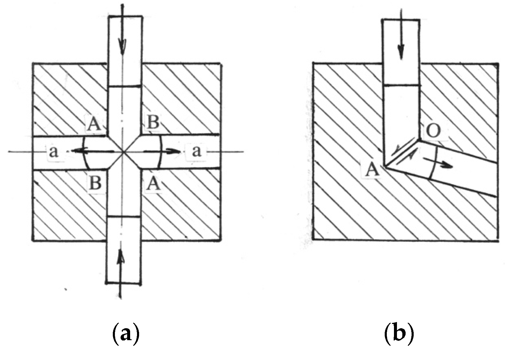
Figure 2.
Slip-line fields for ECAE with friction through sharp-corner (a) and round-corner (b) channels.
Figure 2.
Slip-line fields for ECAE with friction through sharp-corner (a) and round-corner (b) channels.
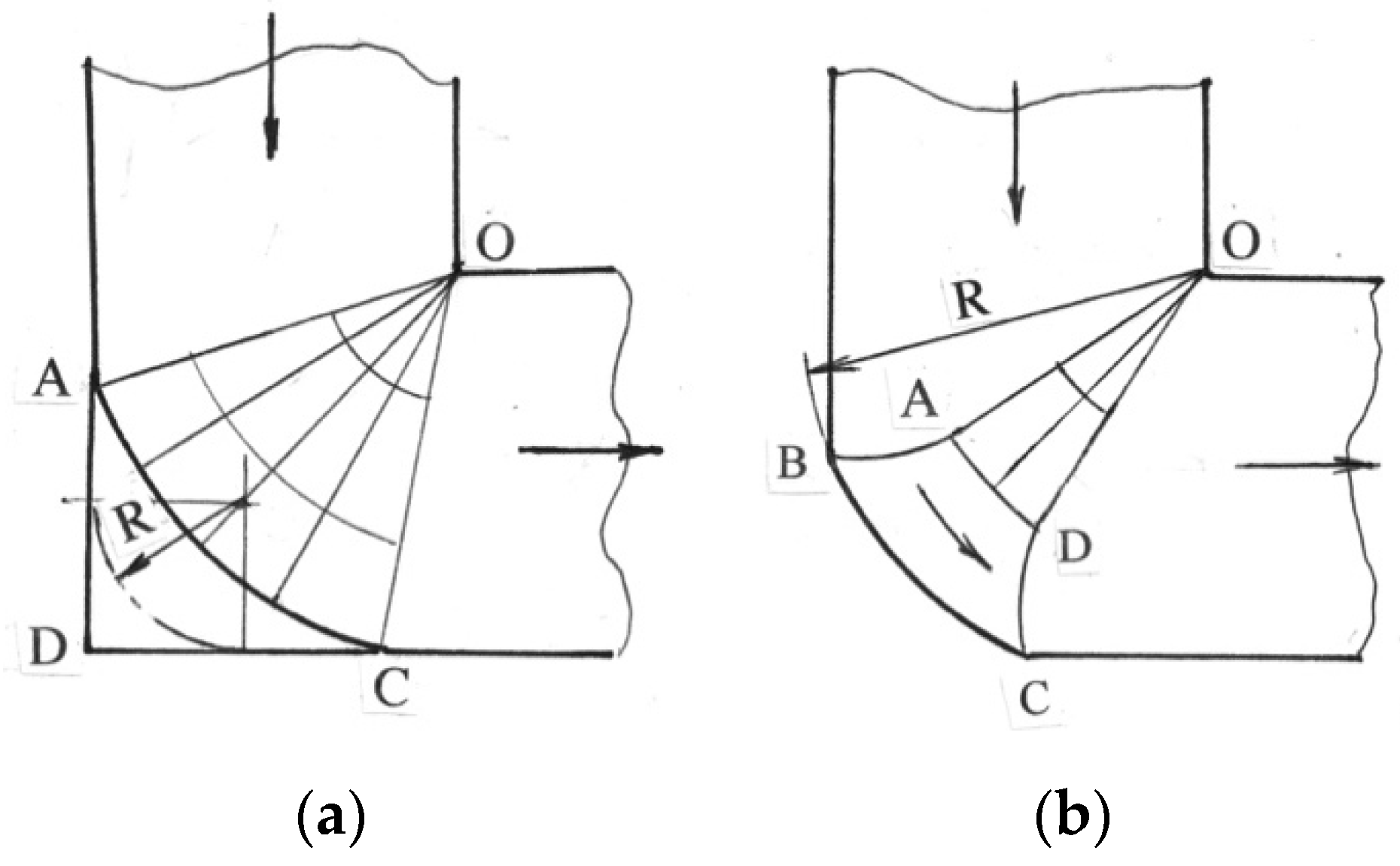
Figure 3.
Slip-line field for frictionless ECAE with intersection angles less than 90° (a) and material bending between channels (b).
Figure 3.
Slip-line field for frictionless ECAE with intersection angles less than 90° (a) and material bending between channels (b).

Figure 4.
ECAE with forming “gap” (a), small-scale localization (b), and re-bending in the outlet channel (c).
Figure 4.
ECAE with forming “gap” (a), small-scale localization (b), and re-bending in the outlet channel (c).
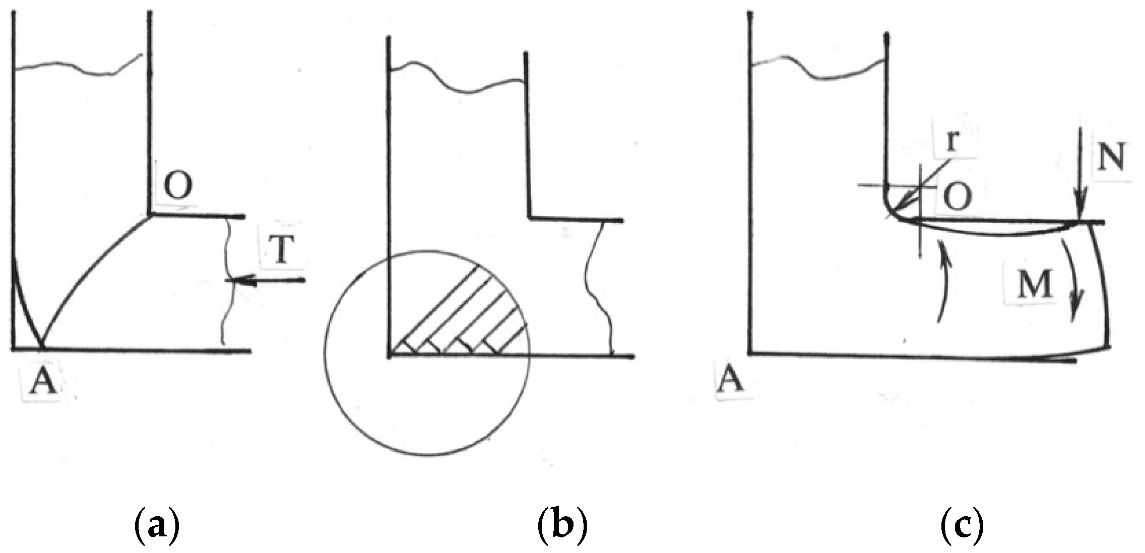
Figure 5.
ECAE die with three movable walls and a balanced slider in the inlet channel (a) and ECAE die with movable sliders in both channels (b).
Figure 5.
ECAE die with three movable walls and a balanced slider in the inlet channel (a) and ECAE die with movable sliders in both channels (b).

Figure 6.
ECAE die with a movable bottom slider for plate billets.

Figure 7.
Continuous Conform–ECAE.

Figure 8.
Die for sc-ECAE.

Figure 9.
An ECAE processing line with a manipulator.

Figure 10.
Billet loading in the die.

Figure 11.
A general view of the large-scale die (a) and a ring assembly (b).

Figure 12.
Large-scale die at the press 11.000t b (a) and sc-ECAE processed billet AA5083 of 100 kg weight (b).
Figure 12.
Large-scale die at the press 11.000t b (a) and sc-ECAE processed billet AA5083 of 100 kg weight (b).
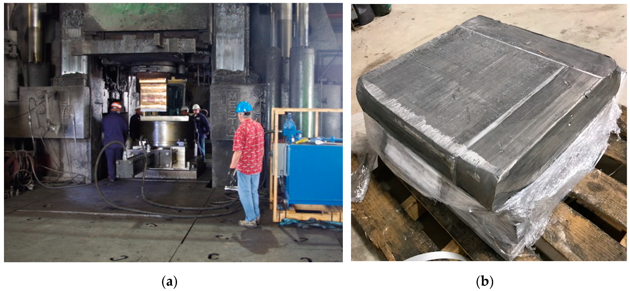
Figure 13.
Concept of an automated sc-ECAE processing line.

© 2020 by the author. Licensee MDPI, Basel, Switzerland. This article is an open access article distributed under the terms and conditions of the Creative Commons Attribution (CC BY) license (http://creativecommons.org/licenses/by/4.0/).
Share and Cite
MDPI and ACS Style
Segal, V. Equal-Channel Angular Extrusion (ECAE): From a Laboratory Curiosity to an Industrial Technology. Metals 2020, 10, 244. https://doi.org/10.3390/met10020244
AMA Style
Segal V. Equal-Channel Angular Extrusion (ECAE): From a Laboratory Curiosity to an Industrial Technology. Metals. 2020; 10(2):244. https://doi.org/10.3390/met10020244
Chicago/Turabian StyleSegal, Vladimir. 2020. "Equal-Channel Angular Extrusion (ECAE): From a Laboratory Curiosity to an Industrial Technology" Metals 10, no. 2: 244. https://doi.org/10.3390/met10020244
Note that from the first issue of 2016, this journal uses article numbers instead of page numbers. See further details here.