Thixoforming and Rheo-Die-Casting of A356/SiC Composite


Abstract
:1. Introduction
2. Materials and Methods
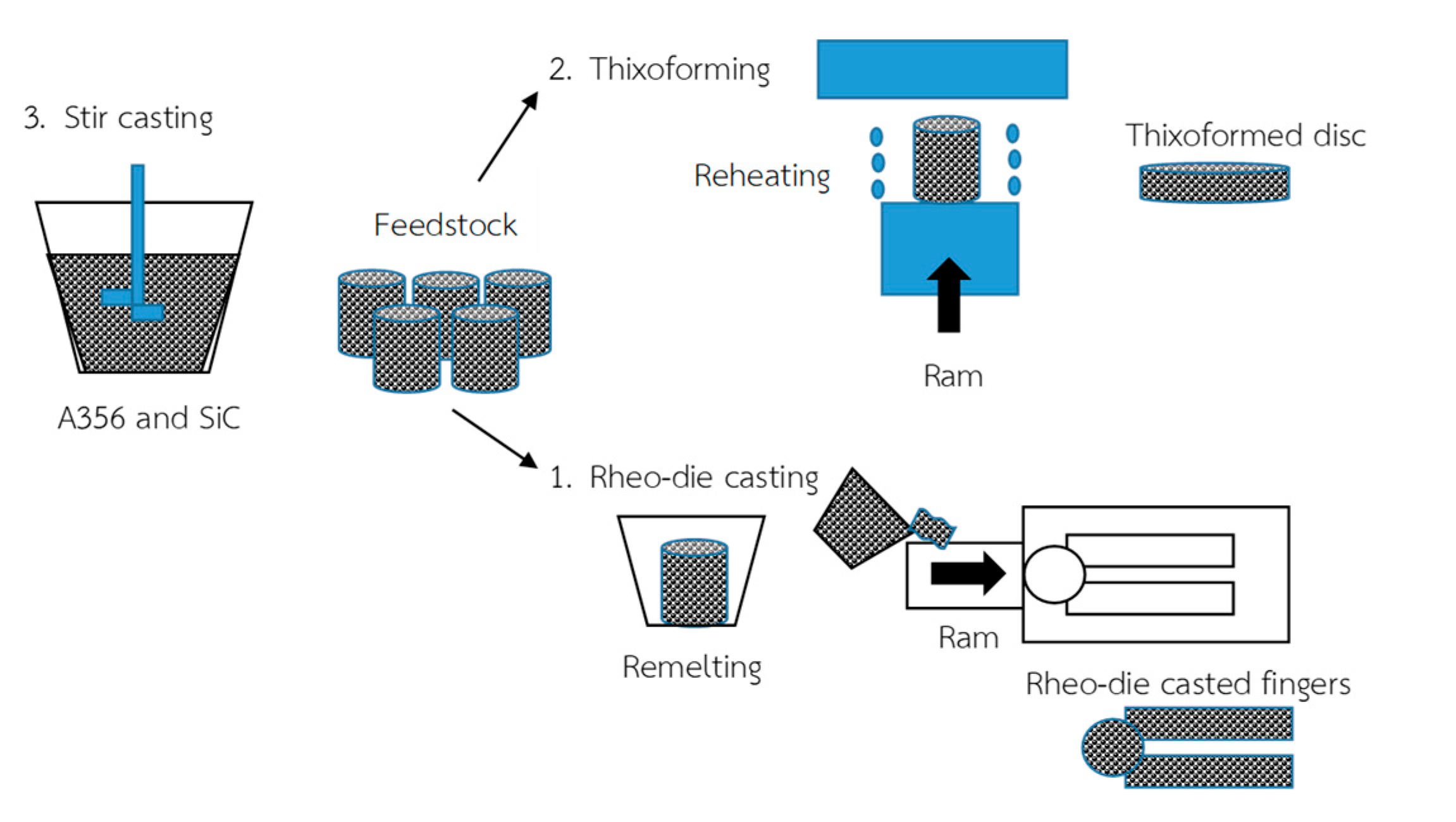
- Stage 1: A356/SiC Feedstock production
- Stage 2: Thixoforming
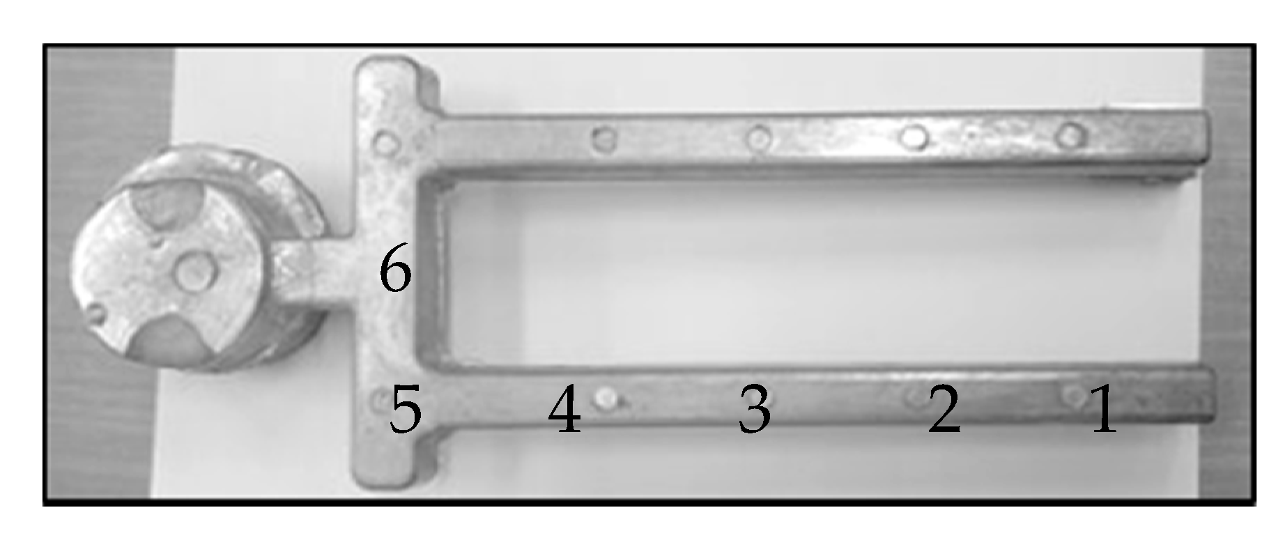
- Stage 3: Rheo-die-casting process
3. Results and Discussion
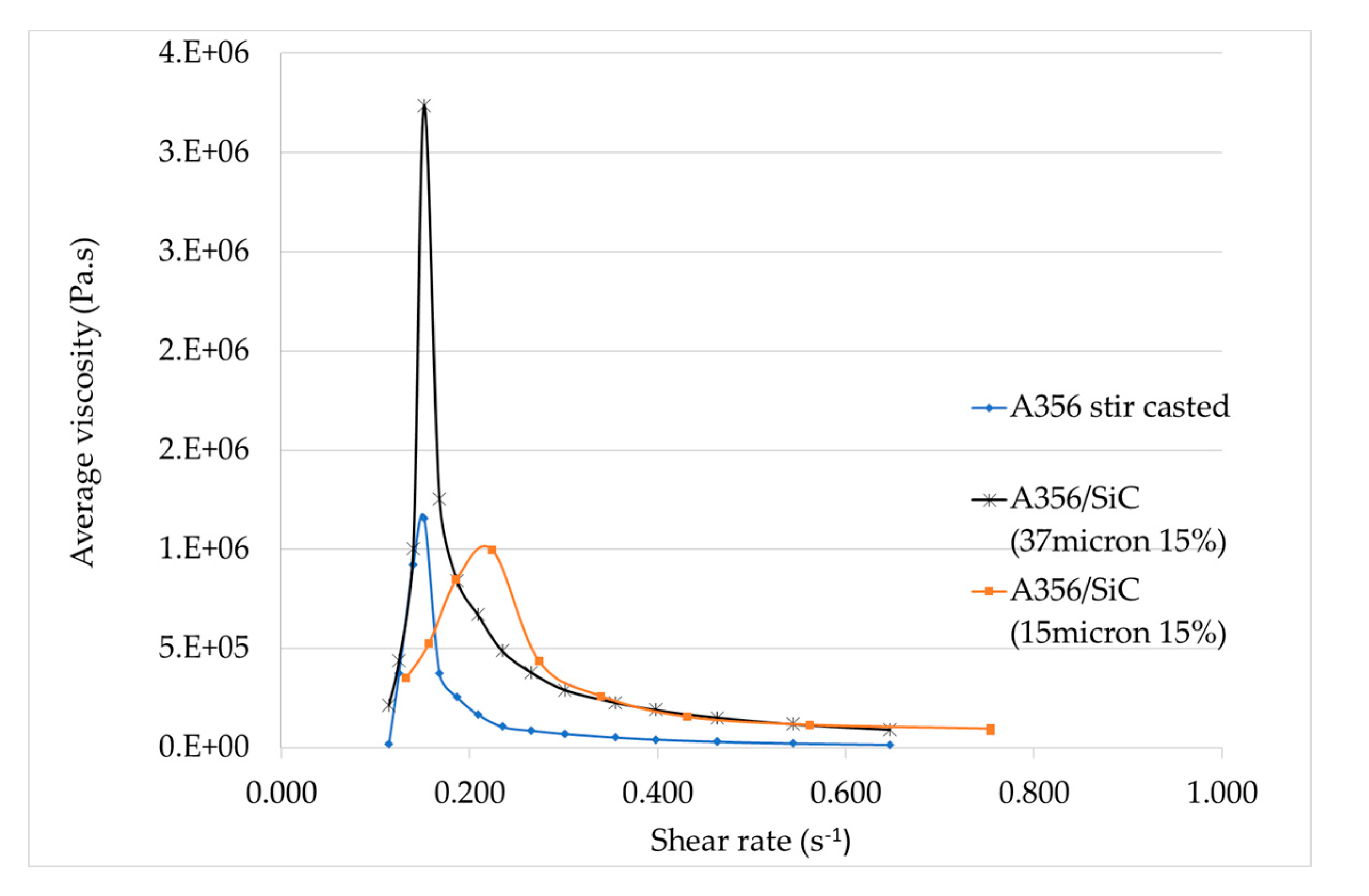
3.1. Semi-Solid Stir-Casting
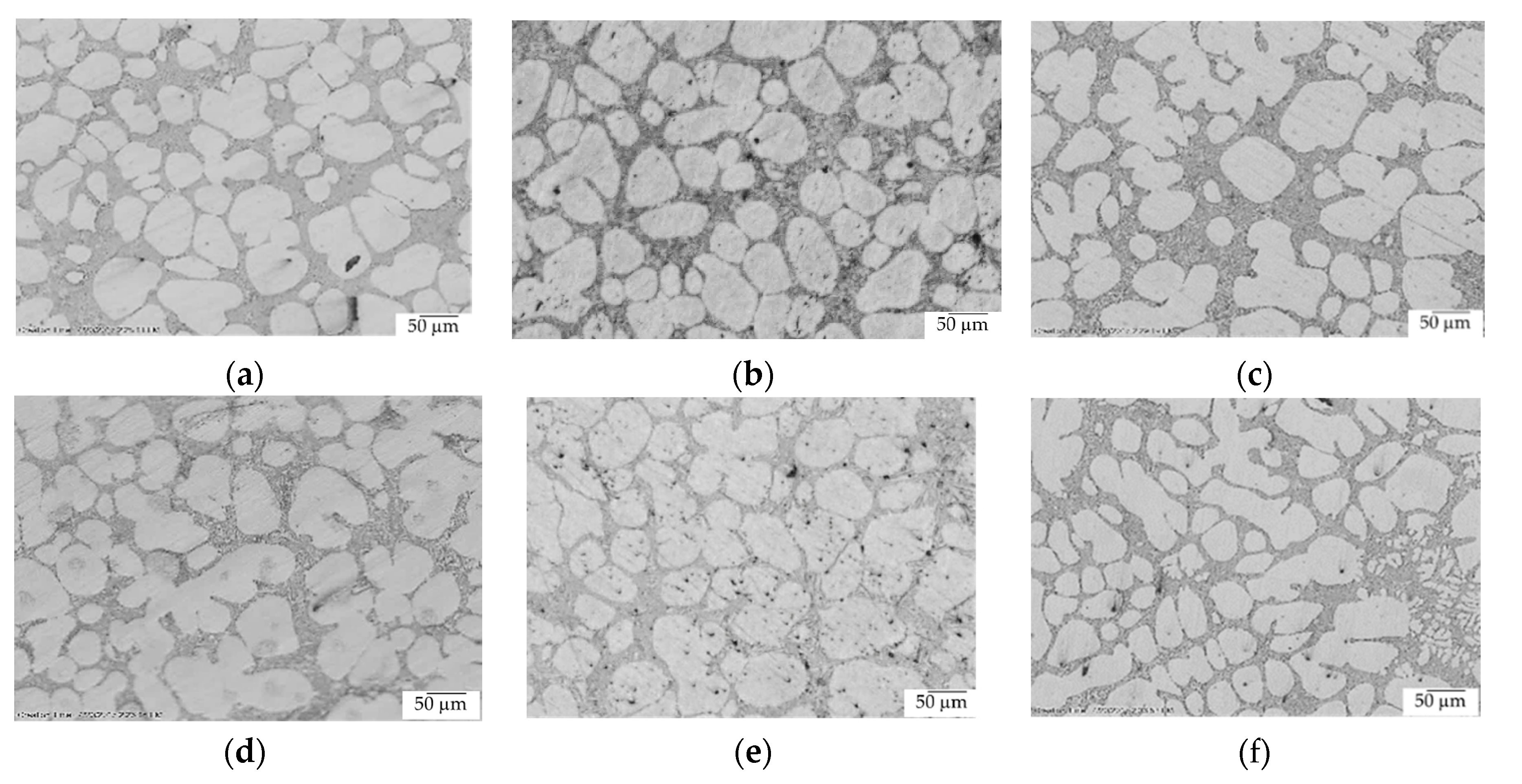
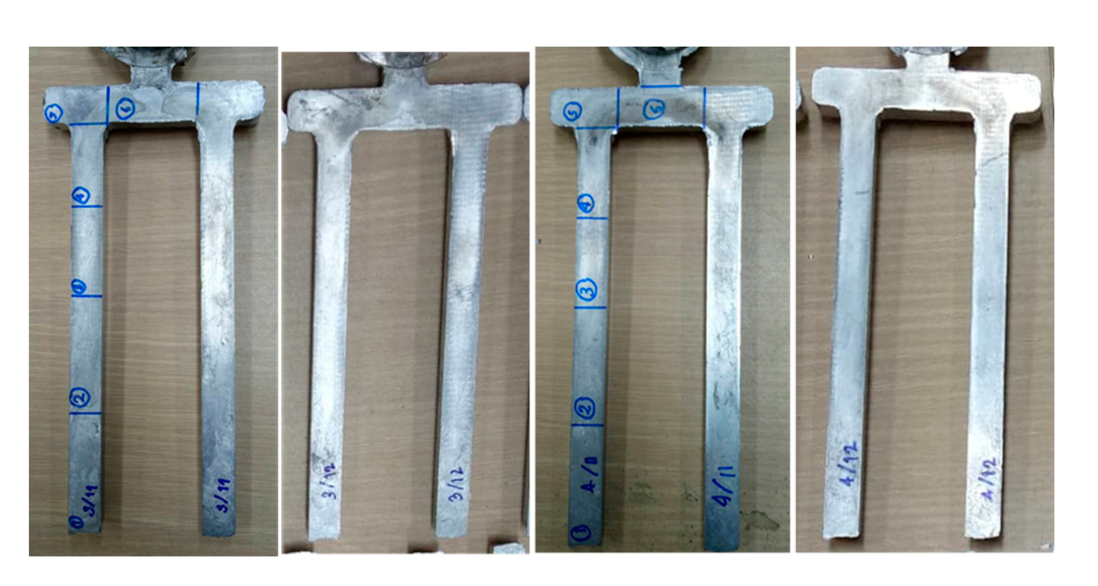
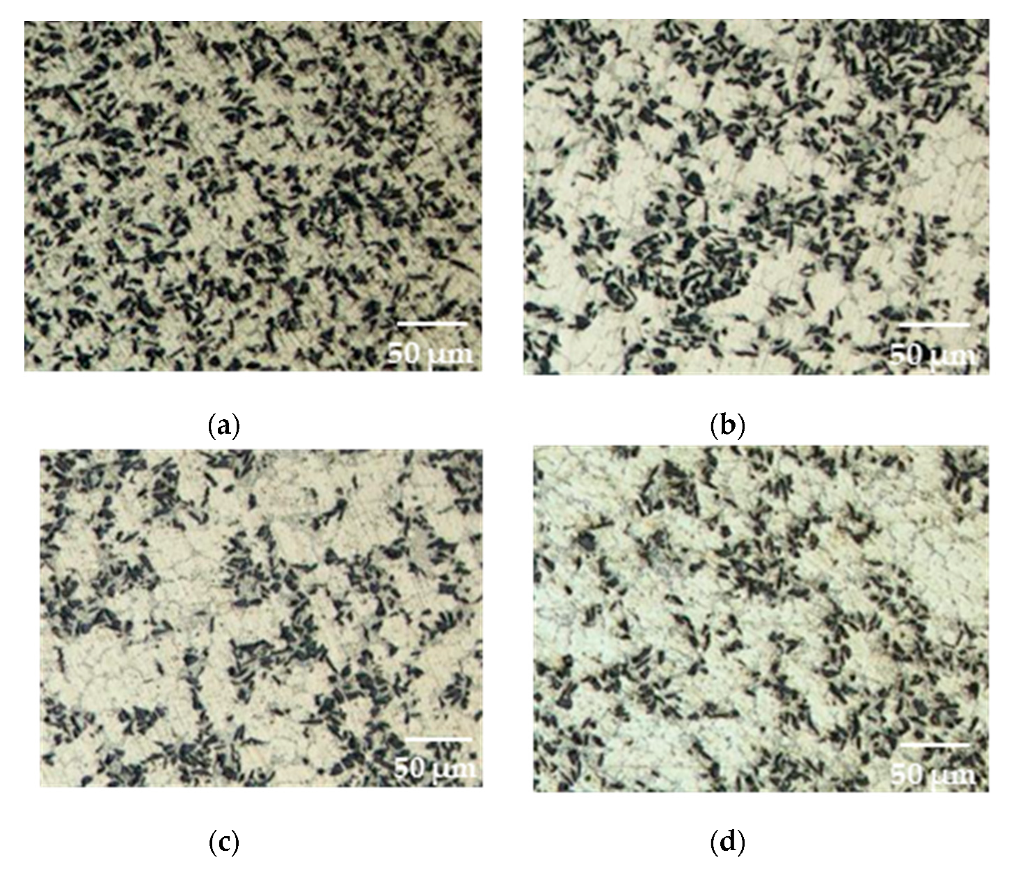
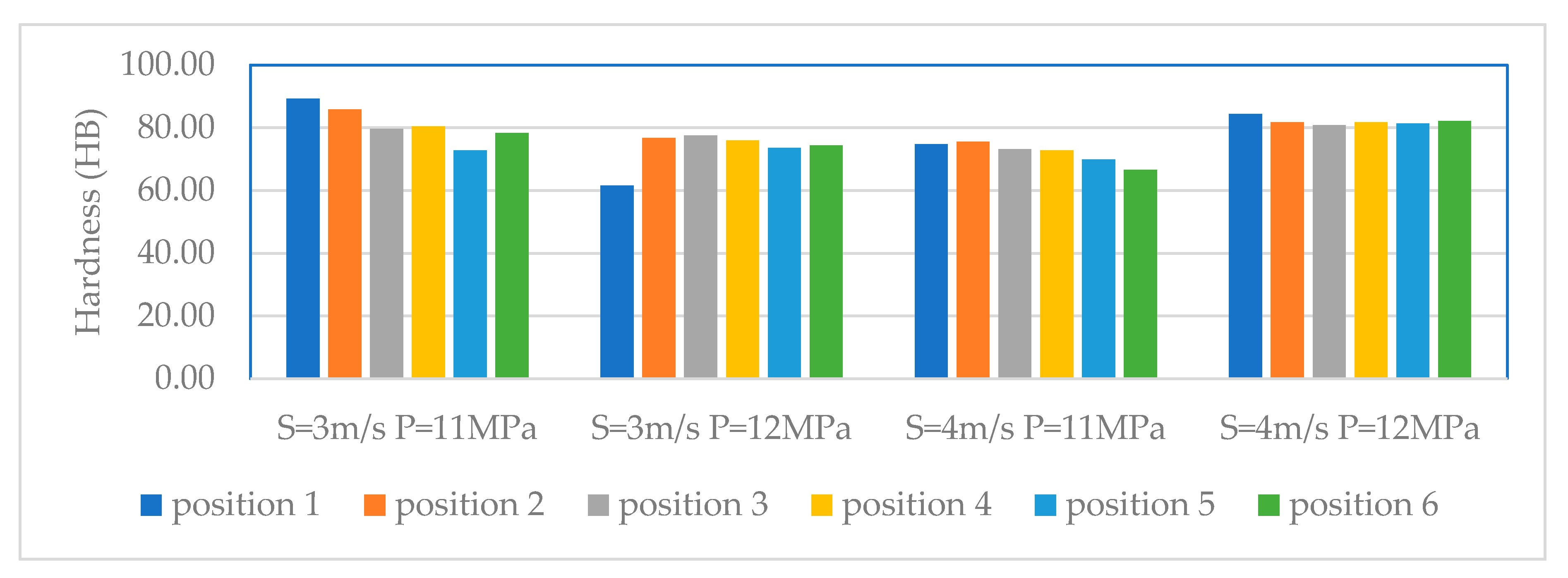
3.2. The Rheo-Die-Casting Process
4. Conclusions
Author Contributions
Funding
Acknowledgments
Conflicts of Interest
References
- Telang, A.F.; Rehman, A.; Dixit, G.; Das, S. Alternate materials in automobile brake disc applications with emphasis on Al composites—A technical review. J. Eng. Res. Stud. 2010, 1, 35–46. [Google Scholar]
- Vencl, A.; Bobic, I.; Arostegui, S.; Bobic, B.; Marinković, A.; Babić, M. Structural mechanical and tribological properties of A356 aluminium alloy reinforced with Al2O3, SiC and SiC+ graphite particles. J. Alloys Compd. 2010, 506, 631–639. [Google Scholar] [CrossRef]
- El-Kady, O.; Fathy, A. Effect of SiC particle size on the physical and mechanical properties of extruded Al matrix nanocomposites. Mater. Des. 2005, 54, 348–353. [Google Scholar] [CrossRef]
- Singla, M.; Dwivedi, D.D.; Singh, L.; Chawla, V. Development of aluminium based silicon carbide particulate metal matrix composite. J. Miner. Mater. Charact. Eng. 2005, 8, 455. [Google Scholar] [CrossRef]
- Saenpong, P.; Talangkun, S.; Laonapakul, T.; Boonma, A. Microstructures and hardness of A356-SiC composites produced by the mechanical stir casting. Mater. Today Proc. 2018, 5, 9489–9496. [Google Scholar] [CrossRef]
- Du, Y.; Zhang, P.; Wang, Y.; Zhang, J.; Yao, S.; Li, C. The uniform distribution of SiC particles in an A356-SiCp composite produced by the tilt-blade mechanical stirring. Acta Metall. Sin. (Eng. Lett.) 2013, 26, 69–74. [Google Scholar] [CrossRef] [Green Version]
- Kandemir, S.; Atkinson, H.V.; Weston, D.P.; Hainsworth, S.V. Thixoforming of A356/SiC and A356/TiB2 nanocomposites fabricated by a combination of green compact nanoparticle incorporation and ultrasonic treatment of the melted compact. Metall. Mater. Trans. A 2014, 45, 5782–5798. [Google Scholar] [CrossRef] [Green Version]
- Fan, Z.; Fang, X.; Ji, S. Microstructure and mechanical properties of rheo-diecast (RDC) aluminium alloys. Mater. Sci. Eng. A 2005, 412, 298–306. [Google Scholar] [CrossRef]
- Guo, H.; Yang, X.; Hu, B.; Zhu, G. Rheo-diecasting process for semi-solid aluminum alloys. J. Wuhan Univ. Technol. Mater. Sci. Ed. 2007, 22, 590–595. [Google Scholar] [CrossRef]
- Yu, W.; Zhao, H.; Wang, L.; Guo, Z.; Xiong, S. The influence of T6 treatment on fracture behavior of hypereutectic Al-Si HPDC casting alloy. J. Alloys Compd. 2018, 731, 444–451. [Google Scholar] [CrossRef]
- Thanh, L.N.; Suéry, M. Microstructure and compression behaviour in the semisolid state of short-fibre-reinforced A356 aluminium alloys. Mater. Sci. Eng. A 1995, 196, 33–44. [Google Scholar] [CrossRef]
- Menargues, S.; Martín, E.; Baile, M.T.; Picas, J.A. New short T6 heat treatments for aluminium silicon alloys obtained by semisolid forming. Mater. Sci. Eng. A 2015, 621, 236–242. [Google Scholar] [CrossRef]
- Long, H.C.; Chen, J.H.; Liu, C.H.; Li, D.Z.; Li, Y.Y. The negative effect of solution treatment on the age hardening of A356 alloy. Mater. Sci. Eng. A 2013, 566, 112–118. [Google Scholar] [CrossRef]
- Laxmanan, V.; Flemings, M.C. Deformation of semi-solid Sn-15 Pct Pb alloy. Metall. Trans. A 1980, 11, 1927–1937. [Google Scholar] [CrossRef]
- Fleming, M.C.; Yurko, J.; Martinez, R. Semi-solid forming: Our understanding today and its implications in improved process. In Proceedings of the 8th International Conference on Semi-Solid Processing of Alloys and Composites, Limassol, Cyprus, 21–23 September 2004. [Google Scholar]
- Shasha, Y.; Peng, Z.; Yunhui, D.; Jun, Z.; Xiaopeng, L. Influence of stirring speed on SiC particles distribution in A356 liquid. China Foundry 2012, 9, 154–158. [Google Scholar]
- Boostani, A.F.; Tahamtan, S. Effect of a novel thixoforming process on the microstructure and fracture behavior of A356 aluminum alloy. Mater. Des. 2010, 31, 3769–3776. [Google Scholar] [CrossRef]
- Haghdadi, N.; Zarei-Hanzaki, A.; Heshmati-Manesh, S.; Abedi, H.R.; Hassas-Irani, S.B. The semisolid microstructural evolution of a severely deformed A356 aluminium alloy. Mater. Des. 2013, 49, 878–887. [Google Scholar] [CrossRef]
- Sadough, S.A.; Rahmani, M.R.; Pouyafar, V. Rheological behavior, microstructure and hardness of A356 aluminum alloy in semisolid state using backward extrusion processs. Trans. Nonferrous Met. Soc. China 2010, 20, 906–910. [Google Scholar] [CrossRef]
- Das, P.; Samanta, S.K.; Ray, T.; Venkatpath, B.R.K. Mechanical properties and Tensile fracture mechanism of Rheocast A356 Al alloy using Cooling Slope. Adv. Mater. Res. 2012, 585, 354–358. [Google Scholar] [CrossRef]
- Hu, X.G.; Zhu, Q.; Atkinson, H.V.; Lu, H.X.; Zhang, F.; Dong, H.B.; Kang, Y.L. A time-dependent power law viscosity model and its application in modelling semi-solid die casting of 319s alloy. Acta Mater. 2017, 124, 410–420. [Google Scholar] [CrossRef] [Green Version]
- Polmear, I.J. Light Alloys Metallurgy of the Light Metals, 3rd ed.; Arnold: London, UK, 1995. [Google Scholar]


| %Composition | Si | Fe | Cu | Mn | Mg | Zn | Ti | Al |
|---|---|---|---|---|---|---|---|---|
| A356 | 7.16 | 0.11 | 0.01 | 0.00 | 0.36 | 0.01 | 0.13 | Balance |
| ASTM * standard | 6.5–7.5 | ≤0.20 | ≤0.20 | ≤0.10 | 0.25–0.45 | ≤0.10 | ≤0.20 | Balance |
| Criteria | Semisolid Process | |
|---|---|---|
| Rheo-Die-Casting | Thixoforming | |
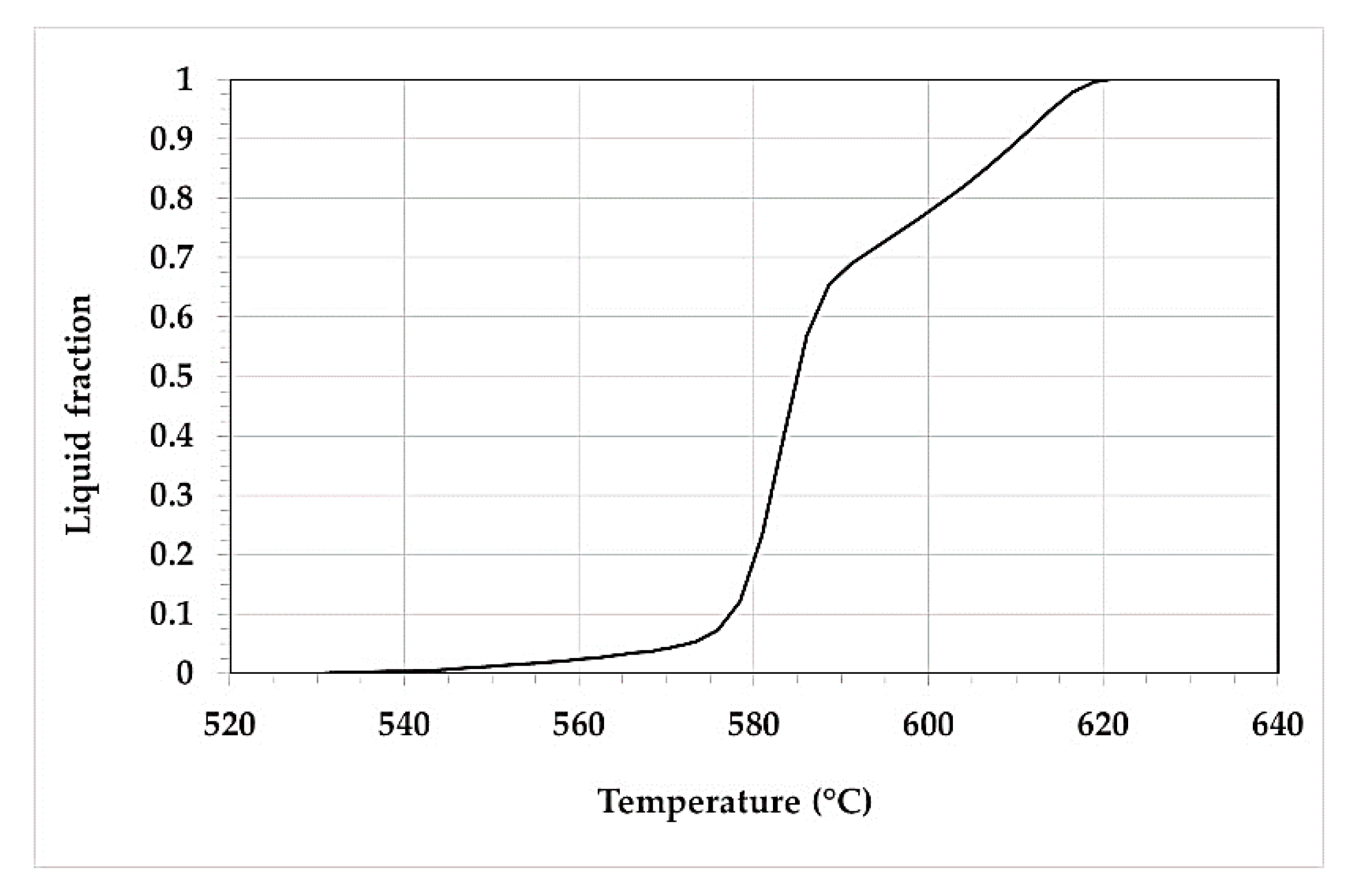
| Fraction liquid | Approximately 0.9 | Approximately 0.4 |
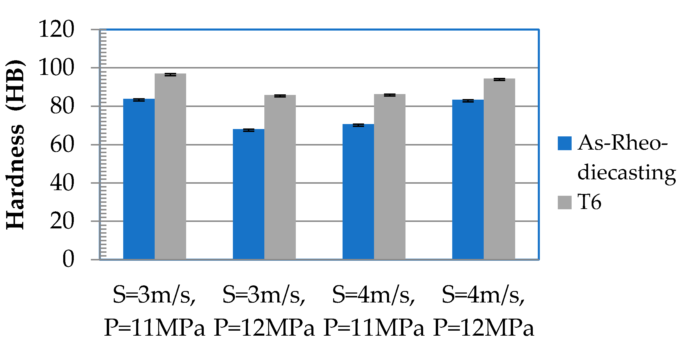
| Pressure | 11 and 12 MPa | 6 MPa |
| Speed | 3 and 4 m/s | 0.016 m/s |
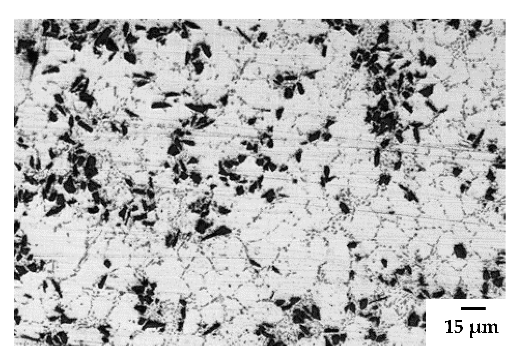
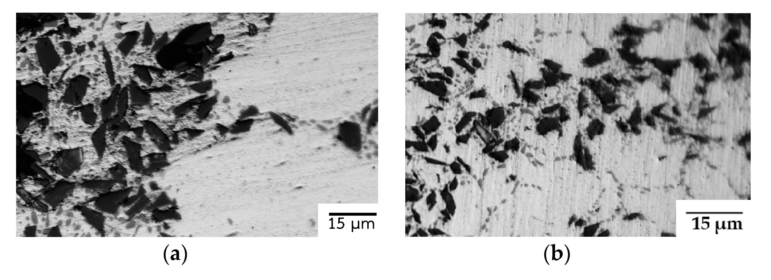
| Microstructure |
|
|
| Hardness |
|
|
© 2020 by the authors. Licensee MDPI, Basel, Switzerland. This article is an open access article distributed under the terms and conditions of the Creative Commons Attribution (CC BY) license (http://creativecommons.org/licenses/by/4.0/).
Share and Cite
Talangkun, S.; Potisawang, C.; Saenpong, P. Thixoforming and Rheo-Die-Casting of A356/SiC Composite. Metals 2020, 10, 251. https://doi.org/10.3390/met10020251
Talangkun S, Potisawang C, Saenpong P. Thixoforming and Rheo-Die-Casting of A356/SiC Composite. Metals. 2020; 10(2):251. https://doi.org/10.3390/met10020251
Chicago/Turabian StyleTalangkun, Sukangkana, Charinrat Potisawang, and Phuriphut Saenpong. 2020. "Thixoforming and Rheo-Die-Casting of A356/SiC Composite" Metals 10, no. 2: 251. https://doi.org/10.3390/met10020251
APA StyleTalangkun, S., Potisawang, C., & Saenpong, P. (2020). Thixoforming and Rheo-Die-Casting of A356/SiC Composite. Metals, 10(2), 251. https://doi.org/10.3390/met10020251