Article

Low Cycle Fatigue Behavior of Elbows with Local Wall Thinning

by
Muhammad Faiz Harun
1,
Roslina Mohammad
1,* and
Andrei Kotousov
2
1
Razak Faculty of Technology and Informatics, Universiti Technologi Malaysia, Jalan Sultan Yahya Petra, Kuala Lumpur 54100, Malaysia
2
School of Mechanical Engineering, The University of Adelaide, Adelaide SA 5005, Australia
*
Author to whom correspondence should be addressed.
Metals 2020, 10(2), 260; https://doi.org/10.3390/met10020260
Submission received: 24 December 2019 / Revised: 10 February 2020 / Accepted: 11 February 2020 / Published: 17 February 2020
(This article belongs to the Special Issue High-Strength Low-Alloy Steels)

Abstract

:
There have been a number of studies concerning the integrity of high-strength carbon steel pipe elbows weakened by local pipe wall thinning, the latter can be typically caused by flow accelerated erosion/corrosion. In particular, the focus of several recent studies was on low cycle fatigue behavior of damaged elbows, mainly, in relation to strength and integrity of piping systems of nuclear power plants subjected to extreme loading conditions, such as earthquake or shutdown. The current paper largely adopts the existing methodology, which was previously developed, and extends it to copper-nickel elbows, which are widely utilized in civil infrastructure in seismically active regions. FE (finite element) studies along with a full-scale testing program were conducted and the outcomes are summarized in this article. The overall conclusion is that the tested elbows with various severity of local wall thinning, which were artificially introduced at different locations, demonstrate a strong resistance against low cycle fatigue loading. In addition, elbows with wall thinning defects possess a significant safety margin against seismic loading. These research outcomes will contribute to the development of strength evaluation procedures and will help to develop more effective maintenance procedures for piping equipment utilized in civil infrastructure.

1. Introduction

Elbows are common components in piping systems, primarily used to change the direction of flow and, therefore, are frequently subjected to flow-induced corrosion and erosion. These structural elements often represent the weakest link in the piping systems due to higher stress concentration and more severe loading conditions in comparison with straight pipe segments. One significant and challenging technical issue in the evaluation of integrity and strength of elbows with local wall thinning is their behavior in the case of extreme events, such as earthquake or shutdown. As elbows are very flexible and, when subjected to extreme loading condition, these structural elements can demonstrate cross-sectional ovalization and local buckling as well as failure in the form of cross-thickness cracking. It was also reported that multi-axial stress state due to bending and internal pressure can lead to reduction of fatigue life [1].
During normal operation, elbows as well as the rest of piping equipment can be subjected to internal pressure, bending loads induced by deadweight or misalignment and thermal expansion, and, in many instances, to temperature gradients. Early research efforts were largely focused on steel elbows under monotonic loading. Numerous experimental studies for different elbow geometries and applied loading conditions, e.g., [2,3,4] supported by extensive finite element studies e.g., [5], were performed with an aim of developing a unified methodology for evaluating integrity and strength of elbows.
Local wall-thinning due to flow-accelerated corrosion/erosion has been recently realized as one of the main degradation mechanisms. It was stated that the effect of the wall thinning on strength and integrity represents a significant issue, specifically for nuclear power plants, since wall-thinning has already led to the failures of carbon steel piping systems in several nuclear power plants in the past [6]. A serious concern is also associated with the operation, behavior and integrity of piping undergoing progressive wall thinning under extreme loading conditions [7], such as the 2011 massive earthquake in Japan. The analysis of damage due to this earthquake has demonstrated the importance of maintaining structural integrity and low cycle fatigue resistance of piping equipment weakened by various defects and accumulated mechanics damage.
There were several recent studies both experimental and numerical addressing the problem of structural integrity and life of carbon steel elbows under severe loading conditions [6,7,8,9,10,11,12,13,14,15,16]. Fatigue life was mainly considered around 50–300 cycles, as this range is representative of a typical earthquake loading. This cycle range can be regarded as occasional loading according to the provisions of both ASME B31.3 [17] and EN 13480-3 [18] standards for process piping. Both standards adopt a similar approach to low-cycle fatigue design, which is based on the allowable stress concept and linear-elastic stress analysis.
Despite extensive previous studies, more experimental and theoretical investigations are still required in order to develop adequate predictive models and incorporate these models into the standards and design codes [1]. The difficulties in prediction methodologies are largely attributed to numerous factors, which influence the strength and integrity of elbows with wall thinning defects [7]. Some of these factors are currently disregarded in design and evaluation procedures or incorporated through the use of large safety factors [6,7,8]. In addition, the current standards, which are oriented for the design of nuclear piping components [17,18], are mainly focused on carbon steel materials providing design fatigue curves for steel elbows in high and low-cycle fatigue regimes. Lack of design guidelines and experimental data for other structural materials is the main motivation behind the current work.
The focus of the present study are elbows made of copper-nickel alloys, which are widely used along with steel elbows in civil infrastructure, in particular, in fuel gas transportation in Malaysia. In this paper, the effect of the localized wall thinning on low cycle fatigue resistance of elbows was investigated by conducting a full-scale test program for elbows with artificially introduced defects. The experimental approach in this work was largely adopted from the similar studies conducted for carbon steel elbows in relation to the nuclear power industry. The fabricated elbow specimens with local wall thinning were subjected to displacement-controlled loading conditions (± 20 mm) until failure. Similar loading conditions have also been utilized in previous studies providing the fatigue life of elbows between 50 and 500 cycles [1]. The present experimental studies were supported by high-fidelity finite element (FE) simulations, which identified main deformation and failure mechanisms. This paper summarizes main outcomes of the experimental program and numerical studies with a focus on the influence of the dimensions and location of thinning defects on low cycle fatigue life. Further, the safety margin against seismic load of elbows with wall thinning was evaluated in accordance with guidelines provided in ASME Boiler and pressure Vessel Code Section III. However, many experimental and numerical results are not presented in this paper due to space limitations and the specific focus of this article. These additional results will be presented and discussed in other publications.

2. Test Specimens and Procedures

2.1. Material and Specimens

The short and long bend elbows of OD = 108 mm and nominal thickness, t n = 2.5 mm, as shown in Figure 1a were fabricated by die casting. The elbows were made of C70600 Copper Nickel 90/10 (90% copper and 10% nickel) as specified in the Malaysia Standards MS930 and MS830. As mentioned in the Introduction, these elbows are widely used in fuel gas pipelines and other industrial applications. For mechanical testing, 90° elbows were welded using Tungsten Inner Gas (TIG) welding machine to straight pipe segments as shown in Figure 1a. Two types of elbows were tested: short radius (R = 102 mm) and long radius (R = 142 mm) elbows; the latter are usually utilized to transport high-viscosity liquids. Table 1 lists basic mechanical properties of the elbow material obtained using standard tensile specimens machined from the intrados and extrados of elbows.
The wall-thinning defects were artificially introduced on the inner side of the elbow wall. These defects were machined at the intrados, crown or extrados center regions, as shown in Figure 1b (one defect for each elbow specimen). The circumferential and axial shapes of the defects had circular geometry. Then, the defect geometry can be specified by the following parameters: L is the equivalent thinning length, θ is the circumferential angle of the defect, which was kept at 90° in the present study and eroded ratio, d / t n .
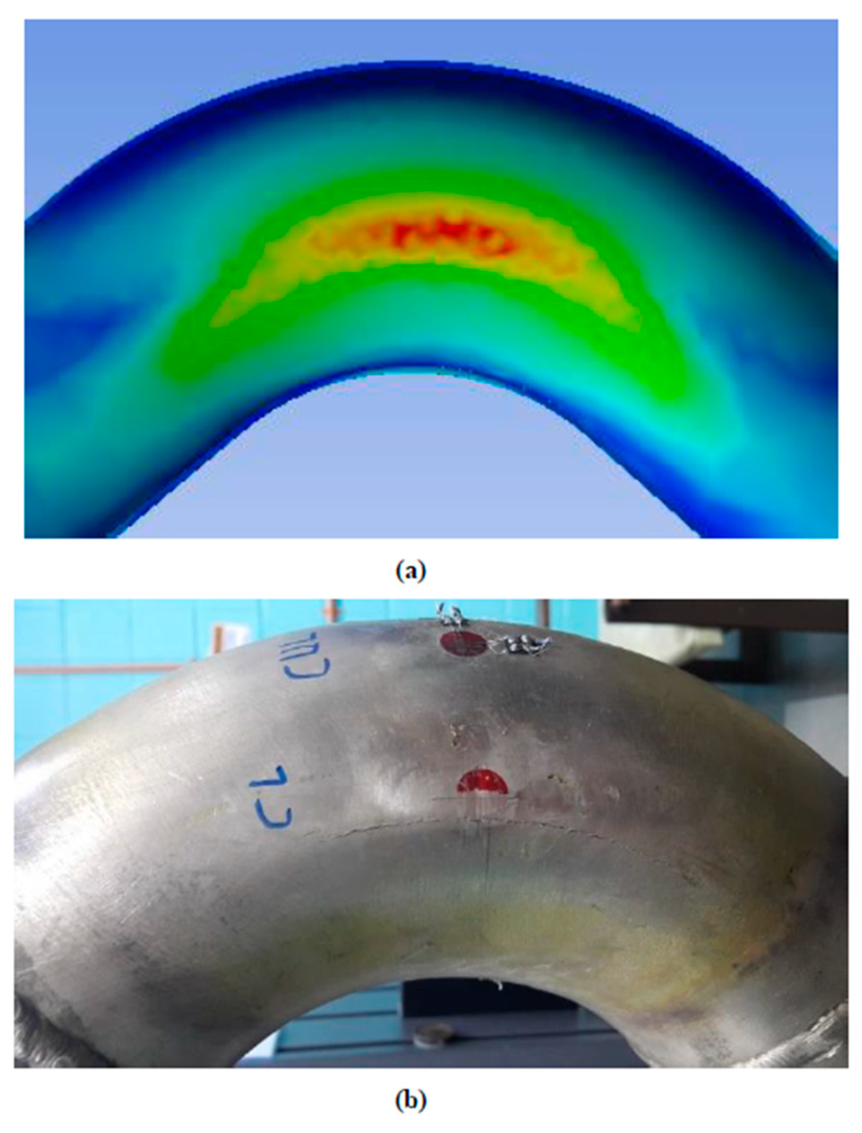
It is well-known from the classical elastic stress analysis of thin-walled donut shells (or membrane shell theory) that the hoop stress largely remains constant, and the magnitude of the hoop stress is similar to the hoop stress in circular pipes loaded by inner pressure. The maximum circumferential stress takes place at the intrados, the minimum stress appears at the extrados region of elbows, while the crown is subjected to an intermediate stress level. However, from our present elasto-plastic FE results, see Figure 2, as well as from previous studies [19], it follows that the crown region can be subjected to the highest stress under closing-mode in-plane bending (in the absence of the inner pressure). Therefore, these results as well as the previous studies justify the consideration of various locations of wall thinning defects as the inner pressure and in-plane bending loading can change the critical locations with the highest stress and strain.

2.2. Testing Apparatus

The testing apparatus used in this study included INSTRON 5982 universal testing machine, the pressurization system, and the data acquisition system. Elbow specimens were equipped with strain gauge rosettes at three critical locations on the outer surface to monitor deformations at intrados, extrados and crown regions during the displacement-controlled loading with and without inner pressure, see Figure 3.
One end of the test specimen was supported by a hinge allowing free rotation, and displacements with the rate of 1 mm/second were applied to the other (top) end of the test specimen, which led to a closing- and opening-mode of in-plane bending. A hand pressure pump was used to pressurize elbow specimens with hydraulic oil. The data acquisition system consisted of a data logger and a PC to capture the experimental data (displacement-load diagram and strain gauges readings). In addition, a digital camera was utilized to monitor the defect formation and failure progression. The summary of the testing conditions of elbows with wall thinning defects is presented in Table 2.

3. Results and Discussion

3.1. Low Cycle Behavior of Sound Elbows

Table 3 shows the low cycle fatigue data (number of cycles to failure) obtained for sound elbows at different values of inner pressure. The maximum values of the internal pressure (4 MPa) were limited due to the use of the hand pressure pump, as at high pressures it was impossible to avoid large pressure fluctuations. Similar problems were reported in [6], where both manual and high-pressure hydraulic pumps were used to pressurize elbows for low and high pressure levels, respectively. Therefore, higher as well as burst pressures were not investigated in the current experimental program.
In all cases for sound elbows failure was observed at crown locations in the circumferential direction as shown in Figure 4. Cracks were not observed at intrados and extrados regions. The failure was identified when the reaction load was decreased or when a crack penetration was observed at the outer surface region of the crown, after that the fatigue test was terminated. These results were used as a benchmark for analysis of damaged elbows.
The experimental data indicates that the excessive inner pressure in the case of long radius elbows slightly reduces the fatigue life of elbows when the inner pressure is above 2 MPa. Based on the life pattern (Table 3), it can be noticed that the inner pressure below this critical value can increase the fatigue life. Indeed, the inner pressure reduces the possibility of local buckling by increasing the overall rigidity of the structure. In other words, the applied inner pressure can reduce the ovalization of elbows, thus lowering the local strain accumulation during cycling, which, in turn, may lead to some increase in fatigue life.
For short radius elbows, the fatigue life is largely unaffected by the inner pressure. This situation can be explained as follows: as the ratio of the short elbow radius to the diameter is quite small (1:1), this makes the elbow wall quite rigid when it was bent towards the in-plane direction. As a result, short elbows have a weaker tendency to local ovalization and buckling. Therefore, the inner pressure has almost no effect on the local strain accumulation during cycling and, subsequently, does not influence fatigue life of elbows.

3.2. Low Cycle Behavior of Elbows with Local Wall Thinning

Table 4 shows the low cycle fatigue data (number of cycles to failure) obtained for elbows with artificial defects at different values of the applied inner pressure.
In almost all elbow specimens with local wall thinning at intrados or extrados, fatigue crack initiated at crown region and normally propagated in the axial directions as it was observed for sound elbows, see Figure 4. It is noted that in many cases, the crack initiated at crown, even for quite severe local wall thinning. Table 4 demonstrates that wall thinning at crown regions has the largest impact on fatigue life, reducing it by approximately 30 percent. The failure initiation at different locations occurred only at a very severe level of wall thinning, when the eroded ratio was 0.75. Wall thinning at extrados and intrados had a very similar effect on low cycle fatigue life of elbows. As expected, a higher eroded ratio, d / t n , led to a shorter fatigue life.
The most interesting observation is the increase of fatigue life with the increase of the applied inner pressure. This behavior has also been found in carbon steel elbows, e.g., [6,20,21], and it can be explained by the inner pressure shielding effect: as the elbow specimen is pressurized, the bending moment is reduced and the overall stiffness of the structure is increased even though the displacement is maintained at an initial set value. In other words, it means that the applied bending load is relaxed by the inner pressure. Another beneficial effect for fatigue life is the reduction of the ovalization and local stress accumulation as discussed previously for sound elbows. Similar to sound elbows, short bend radius elbows with defects exhibit a weaker tendency to local ovalization and buckling, which generally leads to a longer fatigue life as it can be noted from experimental results, Table 4.
It is also can be seen from comparison of Table 3 and Table 4 that the life of the defected short radius elbows is generally longer than the sound elbows (160 to 188 cycles against 166 cycles for sound elbows). The counterintuitive increase in the fatigue life, which also happens for some values of the applied pressure, can be attributed to the decrease of stiffness of the damaged elbows. Under the displacement control loading, this leads to the lower applied stress and less accumulation of fatigue damage in the critical area (crown area).

4. Safety Margin Evaluation

The safety margin of elbows with wall thinning against seismic load can be evaluated with guidelines provided in ASME Boiler and pressure Vessel Code Section III. The current ASME Section III rules for seismic evaluation permit an alternative method for thin-wall piping ( D o / t n > 40). In accordance with this method the fictitious stress amplitude for elbows:
S a = B 1 P D D 0 2 t n + B 2 D o 2 I M E ,
is compared with allowable stress, where PD is inner pressure, D0 is outside diameter of pipe and I is the moment of inertia of the elbow cross-sectional area. The purpose of the present calculations is to evaluate the fictitious stress amplitude and, in the absence of values of the allowable stress, compare this calculated fictitious stress with the yield stress of the material. In the calculations B 1 = 0.5 and:
B 2 = 1.30 h 2 / 3 ;   h = t n R r 2   ,
were utilized [6], where R is the bend radius and r is the nominal mean radius of the elbow.
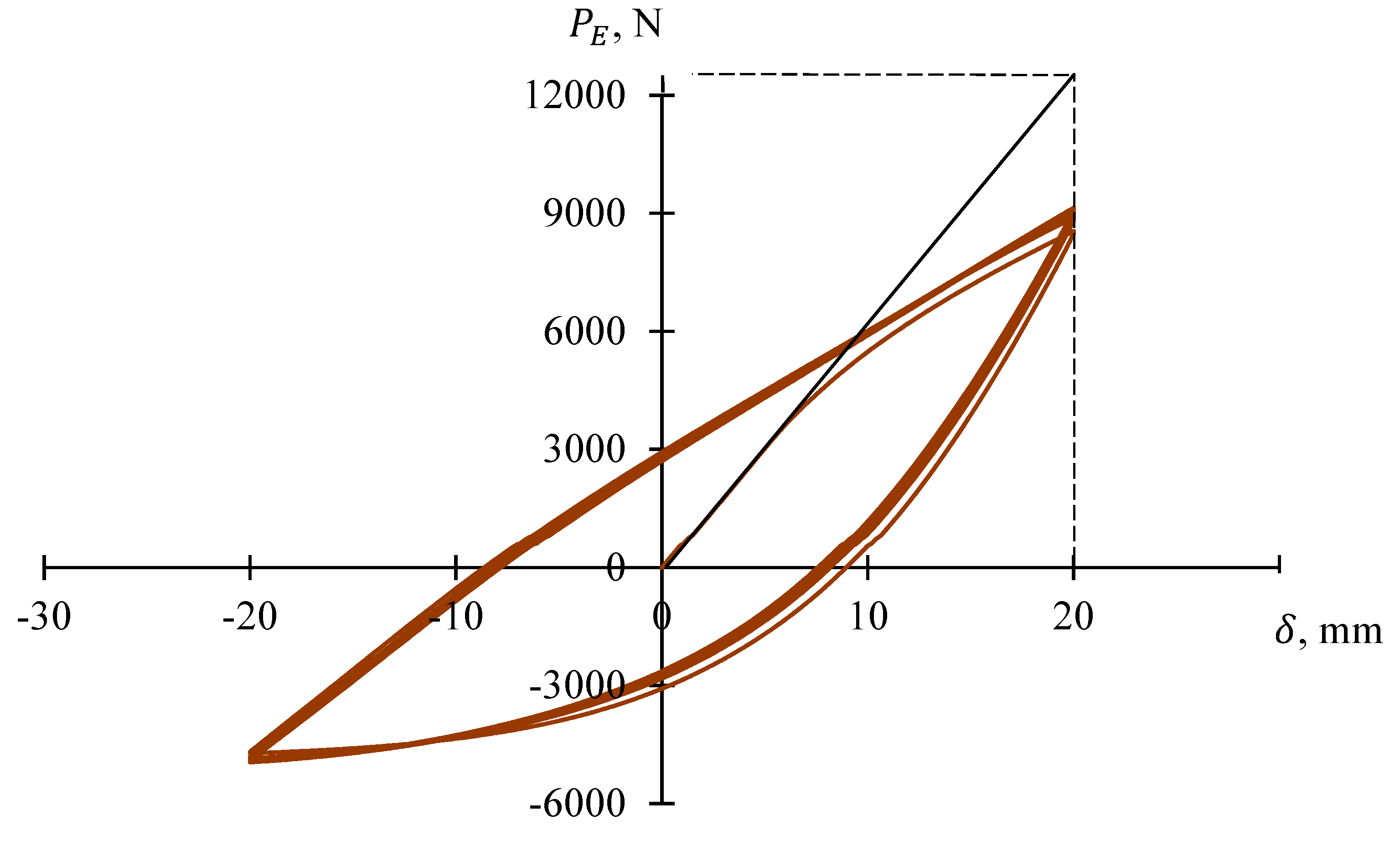
M E = P E l is the moment amplitude corresponding to the maximum displacement of 20 mm, which can be obtained from the fictitious force amplitudes, P E , corresponding to the first ¼ cycle as illustrated in Figure 5 and l is the moment arm, which can be evaluated from Figure 1 for short and long radius elbows.
The fictitious stress amplitudes, S a , of the conducted tests were found between 700 and 800 MPa, and the differences of the value of S a between tests are rather small. A comparison of these values of S a with the material yield stress of 110 MPa indicates a sufficiently large safety margin against occasional loading as the elbow specimens with wall thinning did not collapse or did not reach the maximum loading capacity during the testing [7].

5. Conclusions

Some general conclusions from the experimental results can be summarized as follows:
(1)
Local wall thinning at extrados and intrados regions does not significantly affect low cycle fatigue life of damaged elbows. Fatigue cracks do not initiate at the weakened locations even at large eroded ratios;
(2)
In most cases and regardless of the applied inner pressure, fatigue cracks initiate at the crown regions, and the presence of local wall thinning defect at this location only marginally reduces low cycle fatigue life;
(3)
When the allowable stress is assumed as the material yield stress, and the applied stress level is calculated based on the ASME Boiler and Pressure Vessel Code, Section III, the elbow with wall thinning defects withstood 6–7 times of the allowable stress level, even when the eroded ratio has reached the extreme value of 0.75. This result indicates a sufficiently large safety margin against occasional loading.
More work, however, is still needed, specifically to clarify the explicit safety margin of elbows with defects, the influence of location and severity of wall thinning, eroded ratio, eroded angle and applied pressure. In addition, it has to be noted that the current test results have been obtained for relatively low pressure levels.

Author Contributions

M.F.H. designed, fabricated the elbow sample and performed the experiment. M.F.H. processed the experimental data, performed the analysis, drafted the manuscript and designed the figures together with A.K.; M.F.H. performed the analytic calculations, performed the numerical simulations and verified the analytical methods. R.M. devised the project, the main conceptual ideas and proof outline. R.M. encouraged M.F.H. to investigate the fatigue issues on pipe than supervised the project. M.F.H. and A.K. wrote the manuscript with support from R.M.; A.K. took the lead in writing the manuscript. All authors provided critical feedback and helped shape the research, analysis and manuscript. All authors have read and agreed to the published version of the manuscript.

Funding

The project was funded by the Ministry of Higher Education under Fundamental Research Grant Scheme, MyBrain15 MyPhD, the Ministry of Higher Education, Razak Faculty of Technology and Informatics and Universiti Teknologi Malaysia (UTM). FRGS UTM Vote No.: R.K130000.7840.4F852, UTM Q.K130000.2540.19H15 and Q.K130000.2656.16J42.

Acknowledgments

The authors would like to express their greatest appreciation and utmost gratitude to the Ministry of Higher Education for awarding the Fundamental Research Grant Scheme, MyBrain15 MyPhD, the Ministry of Higher Education, Razak Faculty of Technology and Informatics and Universiti Teknologi Malaysia (UTM) for all the support towards making this study a success.

Conflicts of Interest

The author(s) declared no potential conflicts of interest with respect to the research, authorship, and/or publication of this article.

References

  1. Varelis, G.E.; Karamanos, S. Low-cycle fatigue of pressurized steel elbows under in-plane bending. ASME J. Press. Vessel Technol. 2015, 137. [Google Scholar] [CrossRef]
  2. Sobel, L.H.; Newman, S.Z. Comparison of Experimental and Simplified Analytical Results for the In-Plane Plastic Bending and Buckling of an Elbow. J. Press. Vessel. Technol. 1980, 102, 400–409. [Google Scholar] [CrossRef]
  3. Hilsenkopf, P.; Boneh, B.; Sollogoub, P. Experimental study of behavior and functional capability of ferritic steel elbows and austenitic stainless steel thin-walled elbows. Int. J. Press. Vessel. Pip. 1988, 33, 111–128. [Google Scholar] [CrossRef]
  4. Gresnigt, A.M.; Van Foeken, R. Strength and deformation capacity of bends in pipelines. Int. J. Offshore Polar Eng. 1995, 5, 294–307. [Google Scholar]
  5. Karamanos, S.A.; Giakoumatos, E.; Gresnigt, A.M. Nonlinear Response and Failure of Steel Elbows Under In-Plane Bending and Pressure. J. Press. Vessel. Technol. 2003, 125, 393–402. [Google Scholar] [CrossRef]
  6. Kim, J.-W.; Na, Y.-S.; Lee, S.-H. Experimental Evaluation of the Bending Load Effect on the Failure Pressure of Wall-Thinned Elbows. J. Press. Vessel. Technol. 2009, 131. [Google Scholar] [CrossRef]
  7. Takahashi, K.; Watanabe, S.; Ando, K.; Urabe, Y.; Hidaka, A.; Hisatsune, M.; Miyazaki, K. Low cycle fatigue behaviors of elbow pipe with local wall thinning. Nucl. Eng. Des. 2009, 239, 2719–2727. [Google Scholar] [CrossRef]
  8. Nagamori, H.; Takahashi, K. The Revised Universal Slope Method to Predict the Low-Cycle Fatigue Lives of Elbow and Tee Pipes. J. Press. Vessel. Technol. 2017, 139. [Google Scholar] [CrossRef]
  9. Foroutan, M.; Ahmadzadeh, G.; Varvani-Farahani, A. Axial and hoop ratcheting assessment in pressurized steel elbow pipes subjected to bending cycles. Thin-Walled Struct. 2018, 123, 317–323. [Google Scholar] [CrossRef]
  10. Jeon, B.-G.; Kim, S.-W.; Choi, H.-S.; Park, N.-U.; Kim, N.-S. A Failure Estimation Method of Steel Pipe Elbows under In-plane Cyclic Loading. Nucl. Eng. Technol. 2017, 49, 245–253. [Google Scholar] [CrossRef] [Green Version]
  11. Kim, S.-W.; Choi, H.-S.; Jeon, B.-G.; Hahm, D.-G. Low-cycle fatigue behaviors of the elbow in a nuclear power plant piping system using the moment and deformation angle. Eng. Fail. Anal. 2019, 96, 348–361. [Google Scholar] [CrossRef]
  12. Kiran, A.R.; Reddy, G.; Agrawal, M. Experimental and numerical studies of inelastic behavior of thin walled elbow and tee joint under seismic load. Thin-Walled Struct. 2018, 127, 700–709. [Google Scholar] [CrossRef]
  13. Liu, C.; Shi, S.; Cai, Y.; Chen, X. Ratcheting behavior of pressurized-bending elbow pipe after thermal aging. Int. J. Press. Vessel. Pip. 2019, 169, 160–169. [Google Scholar] [CrossRef]
  14. Udagawa, M.; Li, Y.; Nishida, A.; Nakamura, I. Failure behavior analyses of piping system under dynamic seismic loading. Int. J. Press. Vessel. Pip. 2018, 167, 2–10. [Google Scholar] [CrossRef]
  15. Kiran, A.R.; Reddy, G.; Agrawal, M. Seismic fragility analysis of pressurized piping systems considering ratcheting: A case study. Int. J. Press. Vessel. Pip. 2019, 169, 26–36. [Google Scholar] [CrossRef]
  16. Firoozabad, E.S.; Jeon, B.-G.; Choi, H.-S.; Kim, N.-S. Failure criterion for steel pipe elbows under cyclic loading. Eng. Fail. Anal. 2016, 66, 515–525. [Google Scholar] [CrossRef]
  17. American Society of Mechanical Engineers. Process Piping, B31.3. In ASME Code for Pressure Piping; American Society of Mechanical Engineers: New York, NY, USA, 2006. [Google Scholar]
  18. Comité Européen de Normalisation. Metallic Industrial Piping—Part 3: Design and Calculation, EN13480-3; Comité Européen de Normalisation: Brussels, Belgium, 2002. [Google Scholar]
  19. Urabe, Y.; Takahashi, K.; Ando, K. Low Cycle Fatigue Behavior and Seismic Assessment for Elbow Pipe Having Local Wall Thinning. J. Press. Vessel. Technol. 2012, 134, 041801. [Google Scholar] [CrossRef]
  20. Takahashi, K.; Ando, K.; Matsuo, K.; Urabe, Y. Estimation of Low-Cycle Fatigue Life of Elbow Pipes Considering the Multi-Axial Stress Effect. J. Press. Vessel. Technol. 2014, 136, 041405. [Google Scholar] [CrossRef]
  21. Harun, M.F.; Mohammad, R.; Kotousov, A. Effect of wall thinning on deformation and failure of copper-nickel alloy elbows subjected to low cycle fatigue. Mater. Des. Process. Commun. 2019. [Google Scholar] [CrossRef] [Green Version]
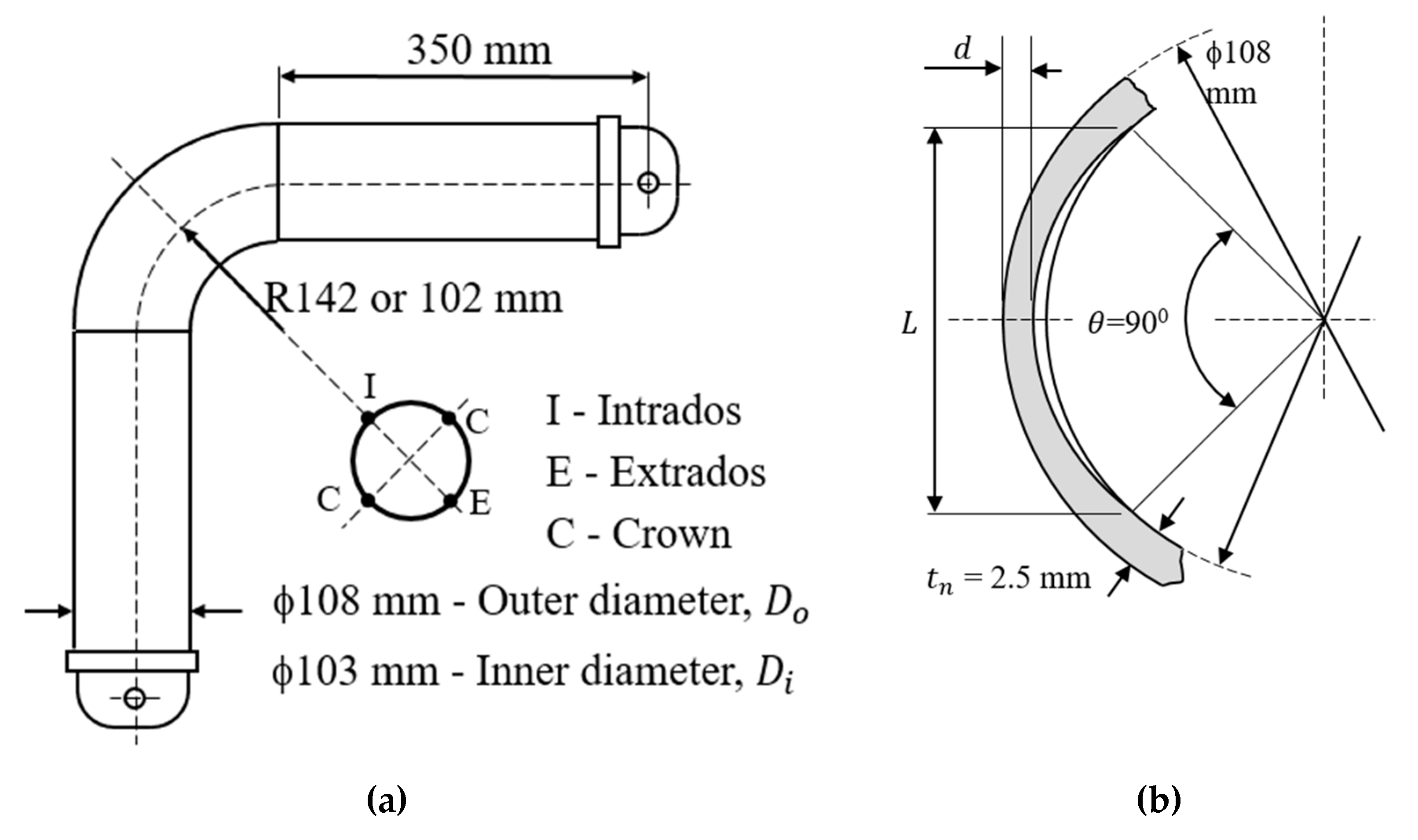
Figure 1. (a) Test specimen and main dimensions; (b) Wall thinning defect sizes.
Metals 10 00260 g001
Figure 2. Distribution of effective stresses under in-plane bending (red area–at crown location shows the highest stress intensity), adapted from [19] with permission from wiley.com, 2019. (a) The FEA three-dimension failure illustration; (b) fatigue failure captured on the elbow after cyclic loading experiment.
Metals 10 00260 g002
Figure 3. Test specimen equipped with strain gauge rosettes.
Metals 10 00260 g003
Figure 4. Fracture (crack penetration) at crown of sound elbow.
Metals 10 00260 g004
Figure 5. Typical load-displacement diagram.
Metals 10 00260 g005
Table 1. Material properties.
Mechanical Properties
Young’s modulus125 GPa
Poisson’s ratio0.3
Ultimate strength300 MPa
Yield strength110 MPa
Hardness80 HB
Table 2. Summary of test conditions for short and long bend elbows.
Test Conditions
Defect Location d / t n L θ Pressure, MPa δ
Extrados0.258090°00.51.01.52.0± 20
0.500.51.01.5-
0.7500.51.01.5-
Crown0.2500.51.01.52.0
0.500.51.01.5-
0.7500.51.01.5-
Intrados0.256000.51.01.52.0
0.500.51.01.5-
0.7500.51.01.5-
Table 3. Total fatigue life (number of cycles to failure) and location of failure for sound elbows.
Types of Elbow RadiusLong Radius ElbowsShort Radius Elbows
Inner Pressure, MPa0123401234
Cycles to Failure208 C220 C210 C204 C196 C165 C166 C166 C166 C166 C
Notations: C—failure at crown region.
Table 4. Total fatigue life (number of cycles to failure) and location of failure for elbows with artificial defects.
Location of Inner Pressure, MPa
Defects Long Bend Radius ElbowsShort Bend Radius Elbows
d / t n 0.00.51.01.52.00.00.51.01.52.0
Extrados0.25193 C195 C196 C198 C200 C176 C179 C181 C185 C188 C
0.5187 C188 C188 C189 C-171 C171 C172 C173 C-
0.75197 C179 C180 C175 E/T-174 C175 E/T176 E/T175 E/T-
Crown0.25184 C187 C191 C195 C190 C169 C170 C170 C171 C172 C
0.5172 C173 C174 C175 C/T-166 C167 C168 C168 C/T-
0.75166 C/T166 C166 C/T165 C/T-163 C163 C160 C155 C/T-
Intrados0.25194 C195 C196 C198 C200 C176 C177 C178 C178 C179 C
0.5198 C199 C200 C201 C-177 C178 C179 C180 C-
0.75201 C196 C192 I/T189 I/T-170 C170 C169 I/T166 I/T-
Notations: C—failure at crown; I—failure at intrados; E—failure at extrados; T—failure in the region of the artificial defect (wall thinning).