Cavitation Peening: A Review


Department of Finemechanics, Tohoku University, Sendai 980-8579, Japan
Metals 2020, 10(2), 270; https://doi.org/10.3390/met10020270
Submission received: 3 January 2020
/
Revised: 12 February 2020
/
Accepted: 14 February 2020
/
Published: 19 February 2020
(This article belongs to the Special Issue Advanced Surface Modification Technologies)
Abstract
:The most popular surface modification technology used to enhance the mechanical properties of metallic materials is shot peening. Shot peening improves fatigue life and strength by introducing local plastic deformation pits. However, the pits increase surface roughness, which is a disadvantage for fatigue properties. Recently, cavitation peening, in which cavitation bubble collapse impacts are used, has been developed as an advanced surface modification technology. The advantage of cavitation peening is the lesser increase in surface roughness compared with shot peening, as no solid collisions occur in cavitation peening. In conventional cavitation peening, cavitation is generated by injecting a high-speed water jet into water. However, cavitation peening is different from water jet peening, in which water column impacts are used. In the present review, to avoid confusing cavitation peening and water jet peening, fundamentals and mechanisms of cavitation peening are described in comparison to water jet peening, and the effects and applications of cavitation peening are reviewed compared with the other peening methods.
Keywords:
surface modification; cavitation peening; shot peening; water jet; pulse laser; ultrasonic1. Introduction
As cavitation causes severe damage to hydraulic machinery such as pumps [1,2], cavitation is harmful to hydraulic components. Impact at cavitation bubble collapse can be used to enhance material properties, similar to shot peening. A peening method using cavitation impact is called “cavitation peening” [3] or “cavitation shotless peening” [4], as shots are not required in cavitation peening. The merit of cavitation peening is that the increase in surface roughness is less than that of conventional shot peening, as no solid collisions occur. In the case of cavitation peening, the impacts at bubble collapses are used; thus, understanding the mechanism of cavitation is important to enhance material properties without erosion.
Although cavitation impacts cause erosion in hydraulic components, cavitation peening can treat metallic materials without causing erosion, as cavitation peening finishes the treatment within the incubation period. The cavitation erosion, i.e., mass loss induced by cavitation, changes with exposure time to cavitation, and is classified into four stages: incubation stage, acceleration, maximum rate, and deceleration [5,6,7]. In the incubation stage, the cavitation impacts that affect the materials produce plastic deformation without mass loss. Note that the threshold level of each material can be obtained experimentally [8]. After the incubation period, the mass loss starts due to a fatigue fracture process, and the mass loss rate increases with time; thus, it is called the acceleration stage. As the optimum processing time of cavitation peening is about 1/25 to 1/5 of incubation period, no mass loss occurs on the treated surface [9]. After the acceleration stage, the mass loss rate reaches a maximum in the maximum rate stage, which then decreases in the deceleration stage.
At the beginning, cavitation peening was developed to mitigate stress corrosion cracking in nuclear power plants by reducing the tensile residual stress of subsurface of stainless steel [10]; it was successfully applied in the plants [11]. After the aggressive intensity of cavitation peening was enhanced by optimizing conditions [4,12], the fatigue strength of mechanical components such as gears improved [13,14,15]. In the present review, the aggressive intensity of cavitation peening is discussed in terms of the cavitation peening results, such as improvement in fatigue strength, work hardening, and introduction of compressive residual stress. Recently, cavitation peening with abrasive particles was proposed to enhance the fatigue properties of additive manufactured titanium alloy by smoothing the surface roughness by introducing compressive residual stress into the subsurface [16]. The history of cavitation peening is described in Section 2.
In commonly used cavitation peening, cavitation is generated by injecting a high-speed water jet into a water-filled chamber. Although the water jet is used for cavitation peening, the mechanism of cavitation peening is different from that of water jet peening, in which shots accelerated by a water jet or water column impacts at the jet center are used [17,18,19,20]. Note that impact at cavitation bubble collapse is used in cavitation peening as mentioned above. The difference between cavitation peening and water jet peening is described in Section 6, and the classification map between cavitation peening region and water jet peening region is introduced in that section.
In this review, to efficiently expand applications of cavitation peening with reliability and safety, the fundamentals and applications of cavitation peening are described compared with other peening techniques.
2. History of Cavitation Peening
To mitigate the stress corrosion cracking of pressure vessels in nuclear power plants, mechanical surface treatments to reduce tensile residual stress in the subsurface in the submerged condition were investigated. At that time, peening methods using a submerged water jet [17] and a submerged pulse laser [21] were proposed. Both methods were successfully applied to nuclear power plants [11,22].
When a high-speed water jet is injected into water through a nozzle or an orifice, cavitation bubbles are generated inside or at the exit of the throat. The submerged water jet with cavitation bubbles is called a cavitating jet. Impulse pressure caused by a submerged high-speed water has two peaks that change with distance from nozzle [23]. When the residual stress on the impinging surface of stainless steel exposed to the cavitating jet was measured changing the standoff distance from the nozzle to the impinging surface, the compressive residual stress showed two peaks as a function of the standoff distance [10]. The peak at the near side of the nozzle was generated by impinging water columns in the jet center, i.e., water jet peening. The peak on the far side of the nozzle was caused by impacts of cavitation bubble collapses, i.e., cavitation peening.
Cutting and testing of materials using a simple cavitating nozzle was proposed [24], and material properties in a cavitation tunnel were improved by cavitation impact [25]. The residual stress on the surface of metal powders was changed by ultrasonic cavitation [26]. However, the treatment area using cavitation impacts is limited when cavitation is produced by cavitation tunnel and/or ultrasonic cavitation. Cavitating jets are suitable for controlling the treatment area and for aggressive intensity cavitation peening.
During the initial stage of cavitation peening development, cavitation is generated by injecting a high-speed water jet into water as mentioned above. In the case of a submerged jet, i.e., a cavitating jet in water, treating outer surfaces of tanks and/or pipelines is difficult. Soyama realized “a cavitating jet in air” by injecting a high-speed water jet into a low speed water jet, which was injected into air without a water-filled chamber, and demonstrated the introduction of compressive residual stress into a metallic surface and the resulting improvement of fatigue strength of stainless steel [27,28] and nitrocarburized steel [29]. The cavitating jet in air research has been followed by Marcon et al. [30,31]. The differences produced by the introduced distribution of compressive residuals stress between a cavitating jet in water and a cavitating jet in air is summarized in Section 4.1.
The main purpose of cavitation peening during the initial stage of development was mitigation of stress corrosion cracking in stainless steel, as mentioned above. In the second stage, cavitation peening was applied to enhance the fatigue properties of metallic materials such as silicon manganese steel [32], aluminum alloy [4,33,34], carbonized chrome molybdenum alloy steel [12], and carbon steel [35] by improving the aggressive intensity of cavitation peening. In this review, the aggressive intensity of the cavitating jet is the ability of the cavitating jet to introduce compressive residual stress, arc height of treated plate, and the erosion rate. To enhance the aggressive intensity of the cavitating jet, a pressurized chamber was used to optimize the cavitating condition considering cavitation number (see Section 4.5). The fatigue strength of actual mechanical components, such as gears [14,36,37] and continuous valuable transmission (CVT) elements [13], was improved. Cavitation peening using a pressurized chamber improves valuable equipment, such as biomedical implants [38].
During the third stage of cavitation peening, to enhance aggressive intensity of the cavitating jet, the nozzle was optimized considering the outlet geometry of the nozzle throat [39]. The outlet bore of the nozzle throat was optimized [40], thereby enhancing the aggressive intensity of the jet by about 20 times. Then, a cavitator was proposed to supply cavitation nuclei into the cavitating jet [41] considering effect of the cavitator on severe cavitation erosion in a centrifugal pump [42]. As the vortices are also important, a guide pipe was placed at the downstream of the nozzle and optimized [41]. The cavitator and guide pipe enhanced each enhanced the aggressive intensity two-fold. Thus, the aggressive intensity of the jet was enhanced by 20 × 2 × 2 = 80 times compared with the first stage of cavitation peening development, as shown in Figure 1. Recently, water flow holes near the nozzle outlet were proposed, and the optimized holes enhanced aggressive intensity by about 34% compared to without holes [43]. The details of effect of nozzle geometry is described in Section 4.3.
During the fourth stage of cavitation peening development, abrasive cavitation peening was proposed [16]. Additive manufactured (AM) metals are attractive materials as the components are directly manufactured from computer-aided design (CAD) data, along with other advantages. However, the limitations of AM metals are the fatigue life and strength due to the rough surface resulting from unmelted metallic particles. Although cavitation peening can improve the fatigue strength of AM metals drastically [44,45], the surface roughness is barely changed. Then, to create a smooth surface by abrasive collision, abrasion was added to the cavitating jet, improving the fatigue strength of titanium alloy manufactured by electron beam melting (EBM) [16]. The polishing inside of holes made by additive manufacturing was also proposed using abrasion and cavitation [46].
3. Cavitation
3.1. What Is Cavitation?
Cavitation is a phase change phenomenon from liquid to gas by decreasing pressure due to increase in velocity [2]. As shown in the Bernoulli equation (Equation (1)), when velocity v increases, pressure p decreases. Thus, when pressure reaches the vapor pressure of liquid pv, the liquid becomes vapor, i.e., gas phase:
where ρL is the density of the liquid.
The most important parameter of cavitating flow is cavitation number σ [2], which is defined by Equation (2). σ is a ratio of dynamic pressure defined by the velocity and the static pressure considering pv:
where p1 and p2 are the upstream and downstream pressure of the orifice or nozzle, respectively, and are absolute pressures. In the case of a cavitating jet, σ can be simplified using Equation (2) because p1 >> p2 >> pv.
Figure 2 illustrates typical aspect of cavitation. In Figure 2, the water flows from the left- to the right-hand side through a Venturi tube [47]. In the narrow region where the pressure decreases due to the increase in flow velocity, water becomes cavitation bubbles, which are shown as white bubbles. In the expanded region where the pressure increases due to the decrease in flow velocity, cavitation collapses. This means that the gas phase becomes the liquid phase. As shown in Figure 2, in the cavitation collapsing region, the string-like cavitation bubbles are observed. In previous studies [1,2], cavitation caused severe erosion through vortex cavitation, as shown in Figure 3 [48]. This vortex cavitation consists of small tiny bubbles. Numerical simulation showed that cloud cavitation, consisting of small tiny bubbles, generates larger shockwaves comparing with a single bubble [49]. Thus, from the cavitation peening viewpoint, the generation of vortex cavitation consisting of tiny bubbles is important for enhancing peening intensity.
Impact at cavitation bubble collapse can be generated by two methods [2]. This first is a microjet, which was observed numerically [50] and experimentally [51,52]. The far side of the bubble from the solid surface deforms, and the vapor–liquid interfaces becomes a microjet. Then, the jet hits the surface. Note that a microjet in vortex cavitation was also observed experimentally [53]. The other method is the shockwave method, created after cavitation shrinking then rebounding due to gas pressure inside the bubble. At the rebound, i.e., expansion, a shockwave is generated. Figure 4 reveals the collapse of a bubble that was induced by a pulse laser using photo elasticity [54]; the behavior of a bubble induced by a pulse laser is similar to that of a cavitation bubble [52,55]. In Figure 4, the upper part is water and lower part is acrylic resin with polarization plates. The aspect was observed by a high-speed video camera. The shrunken bubble is shown in black shadow, as the light source was placed on the other side of the camera. At time (t) = 0 μs, the bubble size was the smallest and increased at t > 0 μs due to the rebound of the bubble. At t > 0 μs, the pressure wave was visualized in a black and white pattern due to photo elasticity. This result shows that the impact was produced at t = 0 μs, and the pressure wave was propagated in the target material.
3.2. How To Generate Cavitation
3.2.1. Hydraulic Cavitation
The most common method used to generate cavitation for cavitation peening is hydraulic cavitation. This means that cavitation is created using a hydrodynamic phenomenon in a narrow flow passage such as a Venturi tube, orifice, and/or nozzle. As shown in Figure 2, cavitation is generated in the narrow region of a Venturi tube, and cavitation can be taken out from the tube by cutting the tube, as shown in Figure 5a [54]. The step type nozzle also creates cavitation inside the nozzle and near nozzle exit, as shown in Figure 5b [54]. Figure 6 shows a schematic diagram of a cavitating jet, a cavitating jet observed with a flush lamp, and the jet observed with a normal light source. To reveal the unsteady periodical aspect of the impinging cavitating jet, Figure 7 shows the impinging jet observed using a high-speed video camera. High-speed observation of a free cavitating jet and a impinging cavitating jet using a high-speed video camera was reported [56], and more details of the impinging jet were provided [57]. The condition of the cavitation jet in Figure 6b,c and Figure 7 was as follows; the injection pressure p1 was 30 MPa, the downstream of the nozzle was at atmospheric pressure, i.e., 0.1 MPa, the nozzle diameter d was 2 mm, and the standoff distance from the upstream corner of the nozzle to the target was 262 mm. When a high-speed water jet is injected into water, cavitation is generated in the vortex core in the shear layer around the jet, where the pressure is lower, as shown in Figure 5b [58,59]. The vortex cavitations combine with each other, creating a big cloud of cavitation, which consists of tiny bubbles, as shown in Figure 6b and Figure 7. When the cloud cavitation reaches the impinging surface, the cloud cavitation becomes a ring vortex cavitation, then part of ring cavitation collapses, producing an impact in a ring region on the target surface. This is why the typical treatment is performed by a fixed cavitating jet, as shown in Figure 8 [3]. In Figure 8, an aluminum specimen is used to clearly show a peening area. Note that when a free and/or impinging cavitating jet is observed using a normal continuous light source with a normal camera, it is very difficult to see the structure of the cavitating jet, as the jet was observed in Figure 6c. Cloud cavitation and/or ring vortex cavitation cannot be observed by such conventional observation. A figure in certain studies [60,61,62] showed that the vortex cavitation in the shear layer directly produces a ring region, but this is incorrect. Actually, the cloud cavitation behavior is important for optimizing cavitation peening, as larger cloud cavitation has a larger impact, which is used for cavitation peening [41], and the size of cloud cavitation is closely related to the frequency of the cloud shedding [41]. The similarity law of the shedding frequency was previously reported [63].
As mentioned above, a submerged high-speed water jet with cavitation, i.e., a cavitating jet in water, is used for conventional cavitation peening. The target should be placed in a water-filled chamber. Thus, treating the outside surface of tanks and pipelines, which are required to be treated by cavitation peening, is difficult. Then, Soyama realized a cavitating jet in air by injecting a high-speed water jet into a low-speed water jet, which was injected into air without a water-filled chamber, and demonstrated the introduction of compressive residual stress into metallic materials [27,64,65]. Typical aspects of a cavitating jet in water and in air are shown in Figure 9 [54]. As the periodical shedding of the cloud cavitation of the cavitating jet synchronizes with the velocity of the low-speed water jet under optimum conditions [64], the surface of the low-speed water jet shows a drastic wavy pattern, as shown in Figure 9. The improvement in the fatigue strength of stainless steel by the cavitating jet in air was also demonstrated compared with that of a cavitating jet in water [28].
To treat a large area, a nozzle consisting of multiple orifices was proposed, and the improvement in fatigue strength of stainless steel was reported [66]. To treat both sides at one time, cavitation peening using opposed cavitating jets was proposed and the fatigue strength of a duralumin plate with a hole was improved [67].
3.2.2. Ultrasonic Cavitation
Cavitation erosion resistance of materials was evaluated using a vibratory test, in which cavitation is generated by ultrasonic vibration [6]. Note that a material test using hydraulic cavitation was standardized by ASTM International [7]. Cavitation induced by ultrasonic vibration is called ultrasonic cavitation. One of major topic related to ultrasonic cavitation is sonochemistry, in which chemical reactions are accelerated by ultrasonic cavitation [68]. Even hydraulic cavitation can be used for chemical processes, and the efficiency of pretreatment of biomass using hydraulic cavitation was found to be 20 times better than that of ultrasonic cavitation [69].
Figure 10 shows typical aspect of ultrasonic cavitation [70]; cavitation was observed at the tip of a vibratory horn. In Figure 10, the aspect of cavitation was observed by an instantaneous photography using a flush lamp. As the aspect of cavitation induced by ultrasonic vibration changed with time, the flush lump was synchronized with the vibration. In Figure 10, the white bubbles are cavitation. At bubble collapse, a shockwave was induced and propagated, then the black circle region, i.e., shock ring, shows where a shockwave was propagated with collapsing the bubble. Compressive residual stress was introduced into stainless steel powders by ultrasonic cavitation [26], and a machining process used created using ultrasonic cavitation [71]. Compressive residual stress was also introduced into metallic materials [72,73]. As shown in Figure 10, cavitation occurs on the tip of the vibratory horn. The effect of horn-tip geometry on ultrasonic cavitation peening was investigated [74]. During ultrasonic cavitation peening, the vibratory horn is placed to the target surface at a certain distance from the target. The aggressive intensity of ultrasonic cavitation drastically changes with the distance from the target [70], which was confirmed both experimentally and theoretically [75]. Unfortunately, the sensitivity of aggressive intensity to the distance using ultrasonic cavitation limits the practical applications. Internal surface finishing was proposed using ultrasonic and abrasive cavitation [76], and the internal surface finishing research has shifted to hydrodynamic abrasive cavitation [77]. Ultrasonic cavitation peening was also used to improve micro-burr-free surfaces [78].
3.2.3. Laser Cavitation
The other typical method used to create cavitation bubbles is a pulse laser [52]. With laser peening, the target can be treated in two ways: a pulse laser is exposed to the target with a water film [79,80,81,82,83,84], or the pulse laser irradiates the target placed in water [3,85,86,87], which is called submerged laser peening. For both laser peening methods, the shockwave induced by laser ablation causes plastic deformation on the material due to containment by the inertia of water. With submerged laser peening, a bubble is generated after laser ablation in the same way to create laser cavitation, as mentioned above. The amplitude of the pressure wave caused by the laser ablation was found to be larger than that of laser cavitation when the shockwave in water was measured using a submerged shockwave sensor [88]. However, the impact induced by the collapse of laser cavitation is larger than that of laser ablation [3,86] when the impact force passing through in the target is measured by a polyvinylidene fluoride (PVDF) sensor, which was developed to detect cavitation impact energy [89,90]. Figure 11 shows typical laser ablation (LA) and laser cavitation (LC) with the output signal from a PVDF sensor and a submerged shockwave sensor. The details are provided in [3,86]. LA and LC were observed using a high-speed video camera. The used pulse laser was a Q-switched Nd:YAG laser with 1064 nm wavelength, a maximum energy of 0.35 J, and a pulse width of 6 ns. The handmade PVDF sensor was installed in the target and the submerged shockwave sensor was placed in water near the target. As mentioned above, the amplitude of the signal from the PVDF sensor at LC collapse was larger than that of LA. The amplitude of the signal from the submerged shockwave sensor with LA was larger than that of LC. Thus, when the focus point of the pulse laser was set in the water, LC can peen the surface without LA [91]. As shown in Figure 11b, the impact induced by secondary collapse was detected at t = 1.54 ms by the PVDF sensor, although the secondary collapse could not be observed by the submerged shockwave sensor (Figure 11c). This is one of reasons why the measurement using the PVDF sensor is reasonable. When the pressure was measured by a hydrophone, the amplitudes of LA and LC were nearly equivalent [92].
4. Key Parameters of Cavitation Peening
4.1. Type of Cavitating Jet
With the conventional method to create cavitation, a submerged high-speed water jet with cavitation, i.e., a cavitating jet in water, is used. As mentioned above, to treat the outside surface of tanks, pipelines, and other components, a cavitating jet in air was constructed [27,64] and the fatigue strength was improved using the cavitating jet in air [28]. A cavitating jet in air is used for the treatment of a skin pass mill work roll [93]. To treat valuable components, such as biomedical implants and/or dies, a cavitating jet in water with a pressurized chamber is used [38,94]. To clearly differentiate the type of cavitating jet on the peening effect, Figure 12 depicts introduced compressive residual stress into stainless steel SUS316L by cavitation peening (CP) using a cavitating jet in water, a cavitating jet in air, and a cavitating jet in a water-pressurized chamber [3]. The surface compressive residual stress introduced by a cavitating jet in air was shown to be larger than that of a cavitating jet in water [3,95]. Note that a cavitating jet in water introduces compressive residual stress in a deeper region than a cavitating jet in air [3,95]. The compressive residual stress introduced using a cavitating jet in water with a pressurized chamber is larger and deeper compared with the others, as shown in Figure 12 [3].
4.2. Standoff Distance
One of most important parameters of cavitation peening is standoff distance, which is defined as the distance from the nozzle to the target [96]. The standoff distance is precisely defined by the distance from the upstream corner of the nozzle to the target, as the flow separates at the corner. Figure 13 shows the relationship between the standoff distance and the curvature 1/ρ, which is calculated from the arc height and chord length of the peened specimen, as shown in the Appendix A, at the injection pressures p1 of 40 and 60 MPa [97]. For shot peening, an Almen strip, whose width is 19 mm, is treated, and the arc height with a chord length of 40 mm is measured, then the arc height is used to evaluate peening intensity. As shown in the Appendix A, the arc height changes with the chord length; however, the curvature is not affected by the chord length. Thus, the curvature 1/ρ is used in the present review. The 1/ρ has two peaks, i.e., the first peak on the near side of nozzle and a second peak on the far side. The first peak is caused by water jet peening and the second by cavitation peening. As shown in Figure 6a, as the cavitation develops and then collapses on the target, a certain distance from the nozzle is required. When the target is set too close to the nozzle, the target is impinged by water columns in the jet center, i.e., water jet peening. As shown in Figure 13, the 1/ρ of the second peak at p1 = 40 MPa is larger than that of the first peak of p1 = 60 MPa. The peening intensity of optimized cavitation peening is larger than that of water jet peening. The details of the differences between water jet peening and cavitation peening are explained in Section 6. Lichtarowicz identified the relationship between the optimum standoff distance sopt, where the aggressive intensity of a cavitating jet has a peak and cavitation number σ, as expressed in Equation (3) [98]:
where d is the nozzle throat diameter and n is a constant. Note that n depends on the nozzle geometry [39]. The optimum standoff distance of similar nozzle geometry can be estimated using Equation (3) at various injection pressures.
4.3. Nozzle Geometry and Diameter
The aggressive intensity of a cavitating jet through a conventional water jet nozzle is very low, although water jets are used for generating cavitation. Figure 14 illustrates a schematic diagram of the relative aggressive intensity of jets from data published in previous reports [39,41]. In Figure 14, nozzles A–E are conventional nozzles for a water jet. Nozzle F is a standard nozzle for material testing using a cavitating jet [7]. As shown in Figure 5 and Figure 6, the vorticial flow near nozzle is very important for generating a powerful cavitating jet. Nozzle G is an optimized nozzle with vorticial flow in the outlet geometry at the nozzle exit [40]. As cavitation is initiated from cavitation nuclei, a cavitator that generates the nuclei was set upstream of the main nozzle (nozzle H); the aggressive intensity was nearly two times larger than without the cavitator (nozzle G) [41]. When the guide pipe, which enhances the vorticial flow and the cloud cavitation, was placed downstream of the nozzle (nozzle I), the aggressive intensity was nearly two times that of nozzle G. When both the cavitator and the guide pipe were used, the aggressive intensity was nearly four times larger than that of nozzle G. The effect of nozzle geometry was also previously discussed [99]. To enhance the flow rate of the cavitating jet at a constant water jet flow rate, water flow holes near the nozzle outlet were used [43]. Note that the nozzle geometries of nozzles F–J are simple and the erosion in the nozzle is minimal compared with the horn-type nozzle.
The other important parameter related to the nozzle is nozzle size, i.e., diameter of the nozzle throat. To demonstrate the peening effect of nozzle size, Figure 15 shows residual stress as a function of the depth from the surface with changing nozzle diameter from 0.35 to 2 mm at p1 = 30 MPa and p2 = 0.1 MPa [100]. The tested material was stainless steel SUS316L. As shown in Figure 15, a larger nozzle can introduce larger compressive residual stress into a deeper region of the stainless steel. The effect of nozzle diameter was also investigated from 0.4 to 0.6 mm at p1 = 16.5 and 16.7 MPa [99]. The scale effect of nozzle size on the aggressive intensity of a cavitating jet was experimentally evaluated, and the power law was reported: the exponent depends on cavitation number [101]. The exponent is 1.56 ± 0.03 at σ = 0.01, 1.97 ± 0.03 at σ = 0.014, and 2.49 ± 0.02 at σ = 0.02 [101].
4.4. Injection Pressure
To reveal the effect of injection pressure at a constant downstream pressure on the introduction of compressive residual stress, Figure 16 shows the residual stress as a function of the depth from the surface. Note that the cavitation number changes with the injection pressure at a constant downstream pressure, as shown in Equation (2). The tested material was the same stainless steel as in Figure 15. The diameter of the nozzle was 0.35 mm and p2 was 0.1 MPa. The effect of cavitation number is explained in the next section. As shown in Figure 16, the compressive residual stress and the depth of the compressive layer barely increased with injection pressure. Comparing the residual stress distribution of d = 2 mm at p1 = 30 MPa in Figure 15 with that of d = 0.35 mm at p1 = 300 MPa in Figure 16, a cavitating jet using a large nozzle at relatively low injection pressure introduces larger compressive residual stress into a deeper region. Note that the jet power of d = 0.35 mm at p1 = 300 MPa and that of d = 2 mm at p1 = 30 MPa are nearly equivalent. A plunger pump of 300 MPa is expensive compared with a 30 MPa pump. When larger nozzles, such as 2 mm in diameter, are used, 10 MPa would be enough to introduce compressive residual stress into stainless steel [102].
4.5. Cavitation Number
As cavitating flow is used for cavitation peening, cavitation number σ, which is defined by Equation (2), is one of the most important parameters. The cavitating region increases with a decrease of cavitation number [2,47]. The aggressive intensity of cavitation through a Venturi tube does not monotonously increase with cavitating length, i.e., a decrease of cavitation number; it peaks at a certain cavitation number [47]. Figure 17 shows the normalized aggressive intensity of a cavitating jet as a function of cavitation number at constant injection pressure [3]. At constant injection pressure, cavitation number increases with increasing downstream pressure. At higher downstream pressures, cavitation bubbles collapse violently, although the bubbles become smaller. At too low a cavitation number, i.e., too low downstream pressure or too high injection pressure, the bubble collapse becomes soft. When cavitation number decreases, the cavitating region increases, but the individual impacts strengthen. This is why the aggressive intensity of the jet peaked at σ = 0.01–0.02, as shown in Figure 17. The aggressive intensity of a cavitating jet with p1 = 98 MPa had a peak at σ = 0.01–0.014 [103], and the jet with p1 = 20 MPa had a peak at σ = 0.014 [104]. The cavitation number, where it peaked, slightly changed with nozzle outlet geometry, but was in the range of 0.01 to 0.02 [105]. As the downstream pressure at the conventional cavitation peening using an open water-filled chamber is at nearly atmospheric pressure, i.e., p2 ≈ 0.1 MPa, from the cavitation number viewpoint, the aggressive intensity of the jet decreases with increasing injection pressure at p1 > 10 MPa as σ < 0.01. From the injection pressure viewpoint, the aggressive intensity of the jet increases. Thus, total aggressive intensity of the jet peaks as a function of injection pressure. The details are provided in Figure 19 as referred to hereinafter.
4.6. Geotrty Effect of Treatment Section
At conventional cavitation peening, a high-speed water jet is injected into a water-filled chamber. As cavitation is hydrodynamic phenomenon, flow pattern affects aggressive intensity of the jet which relates the peening intensity. As it was reported that the erosion induced by the cavitating jet was affected by the size and the geometry of the chamber [106,107], the peening intensity changes with the size and geometry of the chamber.
The peening effect of the water depth of an open chamber was investigated, and the authors found that the water depth needs to be considered to mitigate the cushioning effect caused by air bubbles entrained into the jet [3]. The other main factors are the attack angle of the jet and the shape of the target. The effect of incident angle of the cavitating jet was reported [99,108]. When convex and concave surface were treated by a cavitating jet, the peening area changed with the curvature of the surface [109].
4.7. Scanning Pitch and Speed
As shown in Figure 8, the peening area of the fixed cavitating jet is a ring pattern. To treat a wider area, the jet should scan the target or the target should be moved with a fixed jet. The optimum overlapping scanning pitch of the jet was revealed by estimating the aggressive intensity distribution of the jet [110].
As the individual impact produced by cavitation bubble collapse causes individual plastic deformation, and the compressive residual stresses result from total summation of the plastic deformation, the introduced residual stress σR changes with processing time per unit length tp as described by Equation (4) [65]:
where σ0 and σsat are initial and saturated residual stress, respectively, and a is a constant.
4.8. Water Qualities
As cavitation is a phase change phenomenon from liquid to gas, the temperature and gas content affect the aggressive intensity of the cavitation bubble collapse. The effect of temperature and gas contest on cavitation erosion was revealed using a vibratory cavitation erosion test [111,112,113]. For a cavitating jet, the effect of temperature on erosion rate was confirmed [114,115,116]. The peening intensity was measured as 278–308 K, and the peening intensity was nearly constant at 288–308 K [3]. Han et al. tried to enhance cavitation peening intensity by aeration; however, they concluded that further investigations and process optimization still need to be conducted [35]. As mentioned in Section 4.3, although cavitation nuclei are required for the cavitating jet, the presence of too many air bubbles reduces the impact due to the cushion effect [2]. The usage of oil for cavitation peening was proposed, and compressive residual stress into aluminum alloy was introduced [117].
4.9. Material Properties
To estimate or avoid cavitation erosion, the relationship between cavitation impact and material properties such as hardness was investigated [118]. As cavitation erosion is a kind of fatigue failure, a concept of fundamental threshold level on cavitation erosion was suggested [119]. An experimental method used to obtain the threshold level of materials using a cavitating jet apparatus was proposed, and the threshold levels of metals and plastics were identified [8]. In the case of a single cavitation bubble induced by a pulse laser, the threshold level on peening effect was revealed experimentally, which was confirmed by numerical simulation [120]. To treat harder materials, severe impacts are required or a longer treatment time.
5. Estimation of Aggressive Intensity of Cavitation Peening
As mentioned in Section 4.5, when injection pressure increases, cavitation number decreases. From the cavitation number viewpoint, in the region of σ < 0.01, i.e., p1 > 10 MPa at p2 = 0.1 MPa, increases in the injection pressure decrease the aggressive intensity of the jet. The increase in the injection pressure can increase the aggressive intensity of the jet at a constant cavitation number. Thus, to estimate the aggressive intensity of the jet Icav est at the optimum standoff distance from injection pressure p1 and nozzle diameter d, an experimental formula was proposed as follows [101]:
where Icav ref is a reference aggressive intensity of a jet under the reference condition; the parameters with the subscript ref are those for the reference conditions, Kn depends on the geometry of the nozzle and/or the test section, and nd and np are the exponents of the power laws. The f (σ) is a function of cavitation intensity and is related to cavitation number, and the following equation was proposed [3]:
where σs and pv’ are the correlation factors of the cavitation number and the pseudo vapor pressure, respectively. The aggressive intensity of the jet was estimated using Equation (5) and the difference between the estimated and experimental values is 16% at constant σ [3].
6. Difference between Cavitation Peening and Water Jet Peening
6.1. Standoff Distance
The term ‘water jet peening’ has been used for different peening methods, as shown in Table 1 [95]. To avoid misunderstanding of peening mechanism, the term ‘cavitation peening’ is used for the peening method using cavitation impact, and water jet peening is used for the peening method using water column impacts.
As mentioned in Section 4.2, the first peak results from water jet peening, the second peak is caused by cavitation peening, and the optimum standoff distance sopt is shown in Equation (3) [98]. Then, a classification map for cavitation peening and water jet peening was proposed considering cavitation number σ and sopt, which was normalized by the nozzle throat diameter d, as shown in Figure 18 [95]. More than 150 points [17,39,40,41,96,100,102,106,121,122,123,124,125,126,127] are plotted in Figure 18, and the line described by Equation (7) divides two regions, i.e., the first and second peak regions. The upper right hand region is cavitation peening and the lower left hand side region is the water jet peening region.
The usage of Figure 18 is as follows:
- (1)
- Find the optimum standoff distance sopt changes with distance from the nozzle to the target using experiments.
- (2)
- Calculate sopt/d.
- (3)
- Calculate 1.8 σ−0.6 using Equation (2). Note that p1 and p2 in Equation (2) are absolute pressures.
- (4)
- If experimental sopt/d is larger than the sopt/d obtained in step (3), the peening is cavitation peening.
- (5)
- If experimental sopt/d is smaller than the sopt/d obtained in step (3), the peening is water jet peening. If cavitation peening is desired, find the other optimum standoff distance on the far side of the nozzle using experiments.
6.2. Peening Intensity
To compare the peening intensity between water jet peening and cavitation peening, Figure 19 depicts the peening capability β calculated from arc height changes with injection pressure at constant downstream pressure considering treatment width [97]. For both water jet peening and cavitation peening, the optimum standoff distance was obtained by measuring the arc height with the standoff distance, then the peening capability at the optimum standoff distance was evaluated. As shown in Figure 19a, for water jet peening, β increases with injection pressure. When the power law is assumed, the exponent is about 2.2. In the case of cavitation peening, β has a maximum at p1 = 40 MPa. Note that the maximum value of cavitation peening is 1.7 times larger than that of water jet peening. As the jet power, which is defined by the injection pressure and the flow rate, of 60 MPa is 1.8 times larger than that of 40 MPa, the peening efficiency of cavitation peening is about three times better than that of water jet peening.
7. Comparison between Cavitation Peening and Other Peening Methods
To compare cavitation peening (CP) with the other peening methods, such as shot peening (SP), laser peening (LP), and water jet peening (WJP), Figure 20 shows the results of a plane bending fatigue test of stainless steel [54]. In Figure 20, the amplitude of bending stress was normalized by the fatigue strength of non-peened amplitude of 279 MPa. For all cases, the optimum processing time or optimum pulse density was obtained from the changes in fatigue life at 400 MPa with processing time or pulse density [86]. As shown in Figure 20, the fatigue life of shot peening at 400 MPa was longer than that of cavitation peening; however, the fatigue strength of cavitation peening was stronger than that of shot peening.
A singular characteristic of cavitation peening on the microstrain of quenched tool steel alloy is that the microstrain was relieved by introducing compressive residual stress [128,129]. As expected, many dislocations were introduced by quenching and/or machining. These dislocations can be moved to the grain boundaries and disappear using high frequency vibrations induced by cavitation impacts, as the cyclic loading or ultrasonic vibration move dislocations [130,131,132]. In the case of conventional shot peening, dislocations increased due to solid collision. However, for cavitation peening, the disappearance of dislocations is more frequent compared with the increase in the dislocations, as no solid collisions occur with cavitation peening. The possibility of the movement of dislocations was confirmed by observation using a transmission electron microscope (TEM) [133].
The microstructures of metallic materials treated by cavitation peening were investigated by comparison with other processes [134,135,136]. The increase in surface roughness was less than that of the other processes [134]. When the plastic deformation inside the material was evaluated using the Fry etching method, the depth of the dent of cavitation peening and laser peening was shallower than that of shot peening [137,138], resulting from the difference in the strain speed of the process, as the plastic deformation of cavitation peening and laser peening is caused by the shockwave process.
8. Application of Cavitation Peening
8.1. Suppression of Environmental Assisted Cracking
As mentioned in Section 2, at the beginning, the main purpose of cavitation peening is mitigation of stress corrosion cracking [10,123], which was successfully applied to nuclear power plants [11]. Although cavitation causes erosion and corrosion, cavitation improved the corrosion resistance, as cavitation can generate inactivity layer by oxidation [139]. The electrochemical characteristics induced by cavitation peening were also reported [140].
From the environmental-assisted cracking viewpoint, hydrogen embrittlement and delayed fracture are similar to stress corrosion cracking. The suppression of hydrogen-assisted fatigue crack growth in austenitic stainless steel and delayed fracture resistance on chrome molybdenum steel by cavitation peening were reported [141,142].
8.2. Improvement of Fatigue Properites
Improvements in the fatigue strength of metallic materials, such as aluminum alloy [4,117,143], carbonized steel [12], nitrocarburized steel [29], stainless steel [28], silicon manganese steel [32], and titanium alloy [38], by cavitation peening were reported. Additive manufactured titanium alloy was also tested in comparison with shot peening and laser peening, and the fatigue strength was improved by cavitation peening by about two times in comparison with non-peened [44]. The reasons for the improvement are the increase in yield stress by work hardening and the introduction of compressive residual stress [45]. The actual mechanical components, such as CVT elements [13] and gear [14,15], were treated by cavitation peening and their improvements in fatigue strength were reported. Figure 21 shows a cavitating jet injecting to the gear. The geometry of the gear in Figure 21 is that of the gear tested in the reference [15]. To clarify the mechanism of improvement in fatigue strength by cavitation peening, the crack initiation and crack growth of a surface modified layer treated by cavitation peening were evaluated in comparison with other peening methods [144,145].
8.3. Improvement in Triborogical Properties
As cavitation peening is shotless peening, as mentioned above, cavitation peening can introduce compressive residual stress and work hardening with less of an increase in surface roughness in comparison with other processes. Thus, cavitation peening improves the fretting fatigue properties and/or pitting resistance [37,146,147,148]. The pressure distribution of individual cavitation impact was evaluated using a magnesium-oxide single crystal, and the authors concluded that the highly intense impact was applied to the center [149]. Figure 22 shows the typical plastic deformation pit induced by cavitation impact on pure aluminum compared with ball indentation, which is a model of shot impact [150]. As shown in Figure 22, the edge of the plastic deformation pit induced by cavitation impact is smoother compared with that of ball indentation. The pit induced by the cavitation impact seems to be suitable for an oil pool. This shape can be used for tribological applications.
8.4. Gettering Effect of Silicon Wafer
Cavitation peening can be used for silicon wafers as well as metallic materials, as cavitation impact can be used for the gettering technique. The gettering technique is an essential method used to remove unwanted impurities from active device regions in the manufacturing of semiconductors [151,152,153,154,155]. The most popular and conventional gettering technique is the introduction of backside damage of silicon wafer by impact of SiO2 particles [156,157]. However, the fractions of the particle form an additional source of contamination during subsequent wafer processing. Cavitation peening can introduce backside damage without contamination, as shots are not required. Kumano et al. successfully applied cavitation impacts for the gettering technique, proved by photo-capacitance measurements [158]. Note that impacts that introduce strain without cracks are required for the introduction of the gettering site. This is a typical demonstration that the cavitation impacts induced by the cavitating jet are controllable.
9. Conclusions
In the present review, to reliably and safely apply cavitation peening in practical applications, the research and applications of cavitation peening were reviewed in comparison with water jet peening and other peening methods. To use cavitation peening, the most important aspect is experimental classification between cavitation peening and water jet peening. For cavitation peening, a submerged water jet with a large nozzle at low injection pressure is suitable. The important characteristics of cavitation peening are summarized as follows:
- (1)
- Cavitation peening can mitigate environmentally assisted cracking, such as stress corrosion cracking, hydrogen belittlement, and delayed fracture. It is also applied for the improvement of fatigue strength and tribological properties of metallic materials.
- (2)
- For conventional cavitation peening, a submerged high-speed water jet is used. However, the peening mechanisms of cavitation peening and water jet peening are different. Cavitation peening uses the impacts of bubble collapses. Water jet peening uses water column impacts. Note that submerged high-speed water can also treat the target by water jet peening.
- (3)
- For cavitation peening using an open water-filled chamber, peening intensity has a maximum at a certain injection pressure of about 40 MPa. The peening intensity of cavitation peening at 40 MPa is larger than that of water jet peening at 60 MPa.
- (4)
- Cavitation peening and water jet peening are classified by the relationship between cavitation number and the normalized distance from the nozzle to the target.
- (5)
- Submerged laser peening is a kind of cavitation peening using the impact at the collapse of the bubble, which develops after the laser ablation when it is optimized.
Author Contributions
H.S. conceived and designed the paper; H.S. performed the additional experiments and wrote the paper.
Funding
This research was partly supported by JSPS KAKENHI grant numbers 17H03138 and 18KK0103.
Conflicts of Interest
The author declares no conflict of interest.
Appendix A
Figure A1 depicts a schematic diagram of curvature 1/ρ obtained from the arc height h1 of the chord length L1. Using Pythagorean theorem, radius of curvature ρ is expressed by h1 and L1 as shown in Equation (A1). As shown in Equation (A2), radius of curvature ρ is derived from Equation (A1). Then, the curvature 1/ρ is obtained, as shown in Equation (A3), which is proportional to the arc height, which is normally used for Almen strips to evaluate the intensity of shot peening. As shown in Figure A1, when a different chord length L2 is used, the arc height h2 is different. However, curvature 1/ρ is a unique parameter. Thus, the curvature 1/ρ is used in the present review instead of the arc height.
Figure A1.
Schematic diagram of radius of curvature and arc height.
References
- Soyama, H.; Oba, R.; Kato, H. Cavitation observations of severely erosive vortex cavitation arising in a centrifugal pump. In Proceedings of the Institution of Mechanical Engineers, 3rd International Conference on Cavitation, London, UK, 17–19 March 1992; pp. 103–110. [Google Scholar]
- Brennen, C.E. Cavitation and Bubble Dynamics; Oxford University Press: Oxford, UK, 1995. [Google Scholar]
- Soyama, H. Key factors and applications of cavitation peening. Inter. J. Peen. Sci. Technol. 2017, 1, 3–60. [Google Scholar]
- Soyama, H.; Saito, K.; Saka, M. Improvement of fatigue strength of aluminum alloy by cavitation shotless peening. J. Eng. Mater. Technol. 2002, 124, 135–139. [Google Scholar] [CrossRef]
- Thiruvengadam, A.; Preseir, H.S. On testing materials for cavitation damage resistance. J. Ship Res. 1964, 8, 39–56. [Google Scholar]
- G32-16 Standard test method for cavitation erosion using vibratory apparatus1. ASTM Stand. 2016, 03.02, 1–20.
- G134-17 Standard test method for erosion of solid materials by a cavitating liquid jet. ASTM Stand. 2017, 03.02, 1–17.
- Soyama, H.; Kumano, H. The fundamental threshold level—A new parameter for predicting cavitation erosion resistance. J. Test. Eval. 2002, 30, 421–431. [Google Scholar]
- Soyama, H.; Park, J.D.; Saka, M. Use of cavitating jet for introducing compressive residual stress. J. Manuf. Sci. Eng. Trans. ASME 2000, 122, 83–89. [Google Scholar] [CrossRef]
- Soyama, H.; Yamauchi, Y.; Ikohagi, T.; Oba, R.; Sato, K.; Shindo, T.; Oshima, R. Marked peening effects by highspeed submerged-water-jets-residual stress change on sus304. J. Jet Flow Eng. 1996, 13, 25–32. [Google Scholar]
- Saitou, N.; Enomoto, K.; Kurosawa, K.; Morinaka, R.; Hayashi, E.; Ishikwa, T.; Yoshimura, T. Development of water jet peening technique for reactor internal components of nuclear power plant. J. Jet Flow Eng. 2003, 20, 4–12. [Google Scholar]
- Odhiambo, D.; Soyama, H. Cavitation shotless peening for improvement of fatigue strength of carbonized steel. Int. J. Fatigue 2003, 25, 1217–1222. [Google Scholar] [CrossRef]
- Soyama, H.; Shimizu, M.; Hattori, Y.; Nagasawa, Y. Improving the fatigue strength of the elements of a steel belt for cvt by cavitation shotless peening. J. Mater. Sci. 2008, 43, 5028–5030. [Google Scholar] [CrossRef]
- Soyama, H.; Sekine, Y. Sustainable surface modification using cavitation impact for enhancing fatigue strength demonstrated by a power circulating-type gear tester. Int. J. Sustain. Eng. 2010, 3, 25–32. [Google Scholar] [CrossRef]
- Seki, M.; Nishie, N.; Kozai, S.; Kakuda, M.; Soyama, H.; Naito, A.; Fujii, M. Fatigue strength of steel rollers and gears treated by cavitation peening with short processing time. J. Adv. Mech. Des. Syst. Manuf. 2012, 6, 33–43. [Google Scholar] [CrossRef] [Green Version]
- Soyama, H.; Sanders, D. Use of an abrasive water cavitating jet and peening process to improve the fatigue strength of titanium alloy 6al-4v manufactured by the electron beam powder bed melting (ebpb) additive manufacturing method. JOM 2019, 71, 4311–4318. [Google Scholar] [CrossRef] [Green Version]
- Enomoto, K.; Hirano, K.; Mochizuki, M.; Kurosawa, K.; Saito, H.; Hayashi, E. Improvement of residual stress on material surface by water jet peening. J. Soc. Mater. Soc. Jpn. 1996, 45, 734–739. [Google Scholar] [CrossRef]
- Daniewicz, S.R.; Cummings, S.D. Characterization of a water peening process. J. Eng. Mater. Technol. 1999, 121, 336–340. [Google Scholar] [CrossRef]
- Chillman, A.; Ramulu, M.; Hashish, M. Waterjet peening and surface preparation at 600 mpa: A preliminary experimental study. J. Fluids Eng. Trans. ASME 2007, 129, 485–490. [Google Scholar] [CrossRef]
- Ishiguro, T.; Shimazaki, T.; Terayama, K.; Yoneguchi, A. Effect of hard shot peening with water-jet on surface residual-stress distribution of carburized steels. Tetsu Hagane J. Iron Steel Inst. Jpn. 1994, 80, 131–136. [Google Scholar] [CrossRef] [Green Version]
- Sano, Y.; Mukai, N.; Okazaki, K.; Obata, M. Residual stress improvement in metal surface by underwater laser irradiation. Nucl. Instrum. Methods Phys. Res. Sect. B Beam Interact. Mater. At. 1997, 121, 432–436. [Google Scholar] [CrossRef]
- Yoda, M.; Chida, I.; Okada, S.; Ochiai, M.; Sano, Y.; Mukai, N.; Komotori, G.; Saeki, R.; Takagi, T.; Sugihara, M.; et al. Development and application of laser peening system for pwr power plants. In Proceedings of the 4th International Conference on Nuclear Engineering, Istanbul, Turkey, 25–26 May 2006; pp. 419–424. [Google Scholar]
- Sato, K.; Soyama, H.; Yamauchi, Y.; Ikohagi, T.; Oba, R.; Oshima, R. A study on peening by submerged ultra-high-speed water-jets. In Proceeding of 11th International Conference on Jet Cutting Technology, St. Andrews, Scotland, 8–10 September 1992; pp. 413–424. [Google Scholar]
- Lichtarowicz, A. Use of a simple cavitating nozzle for cavitation erosion testing and cutting. Nat. Phys. Sci. 1972, 239, 63–64. [Google Scholar] [CrossRef]
- Blickwedel, H.; Haferkamp, H.; Louis, H.; Tai, P.T. Modification of material structure by cavitation and liquid impact and their influence on mechanical properties. In Proceedings of the 7th International Conference on Erosion by Liquid and Solid Impact, Cambridge, UK, 7–10 September 1987; pp. 31–36. [Google Scholar]
- Rawers, J.C.; McCune, R.A.; Dunning, J.S. Ultrasound treatment of centrifugally atomized 316 stainless steel powders. Metall. Trans. A 1991, 22A, 3025–3033. [Google Scholar] [CrossRef]
- Soyama, H. Introduction of compressive residual stress using a cavitating jet in air. J. Eng. Mater. Technol. 2004, 126, 123–128. [Google Scholar] [CrossRef]
- Soyama, H. Improvement of fatigue strength by using cavitating jets in air and water. J. Mater. Sci. 2007, 42, 6638–6641. [Google Scholar] [CrossRef]
- Fukuda, S.; Matsui, K.; Ishigami, H.; Ando, K. Cavitation peening to improve the fatigue strength of nitrocarburized steel. Fatigue Fract. Eng. Mater. Struct. 2008, 31, 857–862. [Google Scholar] [CrossRef]
- Marcon, A.; Melkote, S.N.; Castle, J.; Sanders, D.G.; Yoda, M. Effect of jet velocity in co-flow water cavitation jet peening. Wear 2016, 360, 38–50. [Google Scholar] [CrossRef]
- Marcon, A.; Melkote, S.N.; Yoda, M. Effect of nozzle size scaling in co-flow water cavitation jet peening. J. Manuf. Process. 2018, 31, 372–381. [Google Scholar] [CrossRef]
- Soyama, H. Improvement in fatigue strength of silicon manganese steel sup7 by using a cavitating jet. JSME Int. J. Ser. A Solid Mech. Mater. Eng. 2000, 43, 173–178. [Google Scholar] [CrossRef] [Green Version]
- Soyama, H.; Takeo, F. Comparison between cavitation peening and shot peening for extending the fatigue life of a duralumin plate with a hole. J. Mater. Process. Technol. 2016, 227, 80–87. [Google Scholar] [CrossRef]
- Takakuwa, O.; Takeo, F.; Sato, M.; Soyama, H. Using cavitation peening to enhance the fatigue strength of duralumin plate containing a hole with rounded edges. Surf. Coat. Technol. 2016, 307, 200–205. [Google Scholar] [CrossRef]
- Han, B.; Ju, D.Y.; Jia, W.P. Influence of water cavitation peening with aeration on fatigue behaviour of sae1045 steel. Appl. Surf. Sci. 2007, 253, 9342–9346. [Google Scholar] [CrossRef]
- Soyama, H.; Macodiyo, D.O. Fatigue strength improvement of gears using cavitation shotless peening. Tribol. Lett. 2005, 18, 181–184. [Google Scholar] [CrossRef]
- Seki, M.; Soyama, H.; Fujii, M.; Yoshida, A. Rolling contact fatigue life of cavitation-peened steel gear. Tribol. Online 2008, 3, 116–121. [Google Scholar] [CrossRef] [Green Version]
- Takakuwa, O.; Nakai, M.; Narita, K.; Niinomi, M.; Hasegawa, K.; Soyama, H. Enhancing the durability of spinal implant fixture applications made of ti-6al-4v eli by means of cavitation peening. Int. J. Fatigue 2016, 92, 360–367. [Google Scholar] [CrossRef]
- Soyama, H. Effect of nozzle geometry on a standard cavitation erosion test using a cavitating jet. Wear 2013, 297, 895–902. [Google Scholar] [CrossRef]
- Soyama, H. Enhancing the aggressive intensity of a cavitating jet by means of the nozzle outlet geometry. J. Fluids Eng. 2011, 133, 1–11. [Google Scholar] [CrossRef]
- Soyama, H. Enhancing the aggressive intensity of a cavitating jet by introducing a cavitator and a guide pipe. J. Fluid Sci. Technol. 2014, 9, 1–12. [Google Scholar] [CrossRef] [Green Version]
- Soyama, H.; Uranishi, K.; Ito, Y.; Kato, H.; Ichioka, T.; Oba, R. Hard-erosion-progress in a typical centrifugal pump (1st report, marked effects of upstream cavitators). Turbomachinery 1990, 18, 691–698. [Google Scholar]
- Kamisaka, H.; Soyama, H. Enhancement of an aggressive intensity of a cavitating jet by water flow holes near nozzle outlet. Trans. JSME 2019. [Google Scholar] [CrossRef]
- Soyama, H.; Okura, Y. The use of various peening methods to improve the fatigue strength of titanium alloy ti6al4v manufactured by electron beam melting. AIMS Mater. Sci. 2018, 5, 1000–1015. [Google Scholar] [CrossRef]
- Okura, Y.; Sasaki, H.; Soyama, H. Effect of meczhanical properties on fatigue life enhancement of additive manufactured titanium alloy treated by various peening methods. In Advanced Surface Enhancement, INCASE 2019, Lecture Notes in Mechanical Engineering; Springer Nature Singapore Pte Ltd.: Singapore, 2020; pp. 88–96. [Google Scholar]
- Nagalingam, A.P.; Yeo, S.H. Effects of combined wear mechanisms in internal surface finishing using controlled hydrodynamic cavitation abrasive finishing process. In Advanced Surface Enhancement, INCASE 2019, Lecture Notes in Mechanical Engineering; Springer Nature Singapore Pte Ltd.: Singapore, 2020; pp. 244–253. [Google Scholar]
- Soyama, H.; Hoshino, J. Enhancing the aggressive intensity of hydrodynamic cavitation through a venturi tube by increasing the pressure in the region where the bubbles collapse. AIP Adv. 2016, 6, 1–13. [Google Scholar] [CrossRef] [Green Version]
- Soyama, H.; Ohba, K.; Takeda, S.; Oba, R. High-speed observations of highly erosive vortex cavitation around butterfly valve. Trans. JSME 1994, 60B, 1133–1138. [Google Scholar] [CrossRef]
- Reisman, G.E.; Wang, Y.C.; Brennen, C.E. Observations of shock waves in cloud cavitation. J. Fluid Mech. 1998, 355, 255–283. [Google Scholar] [CrossRef] [Green Version]
- Plesset, M.S.; Chapman, R.B. Collapse of an initially spherical vapour cavity in neighbourhood of a solid boundary. J. Fluid Mech. 1971, 47, 283–290. [Google Scholar] [CrossRef] [Green Version]
- Crum, L.A. Surface oscillations and jet development in pulsating bubbles. J. De Phys. Colloq. 1979, 40, 285–288. [Google Scholar] [CrossRef] [Green Version]
- Lauterborn, W.; Bolle, H. Experimental investigations of cavitation-bubble collapse in neighborhood of a solid boundary. J. Fluid Mech. 1975, 72, 391–399. [Google Scholar] [CrossRef]
- Dominguez Cortazar, M.A.; Franc, J.P.; Michel, J.M. The erosive axial collapse of a cavitating vortex: An experimental study. J. Fluids Eng. 1997, 119, 686–691. [Google Scholar] [CrossRef]
- Soyama, H. Fundamentals and applications of cavitation peening comparing with shot peening and laser peening. In Advanced Surface Enhancement, INCASE 2019, Lecture Notes in Mechanical Engineering; Springer Nature Singapore Pte Ltd.: Singapore, 2020; pp. 76–87. [Google Scholar]
- Philipp, A.; Lauterborn, W. Cavitation erosion by single laser-produced bubbles. J. Fluid Mech. 1998, 361, 75–116. [Google Scholar] [CrossRef]
- Soyama, H.; Yamauchi, Y.; Adachi, Y.; Sato, K.; Shindo, T.; Oba, R. High-speed observations of the cavitation cloud around a high-speed submerged water-jet. JSME Int. J. 1995, 38B, 245–251. [Google Scholar] [CrossRef] [Green Version]
- Kamisaka, H.; Soyama, H. Periodical shedding of cavitation cloud induced by a cavitating jet. Proc. 23rd Int. Conf. Water Jet. 2018, 111–123. [Google Scholar]
- Soyama, H.; Lichtarowicz, A.; Momma, T. Vortex cavitation in a submerged jet. In Proceedings of the 1996 ASME Fluids Engineering Division Summer Meeting, San Diego, CA, USA, 7–11 July 1996; FED-236. pp. 415–422. [Google Scholar]
- Soyama, H.; Lichtarowicz, A. Cavitating jets—Similarity correlations. Jet Flow Eng. 1996, 13, 9–19. [Google Scholar]
- Ohya, T.; Okimura, K.; Ohta, T.; Ichioka, T. Residual stress improved by water jet peening for small-diameter pipe inner surfaces. Mitsubishi Heavy Ind. Ltd. Tech. Rev. 2000, 37, 52–55. [Google Scholar]
- Demma, A.; Frederick, G. Program on technology innovation: An evaluation of surface stress improvement technologies for pwscc mitigation of alloy 600 nuclear components. In Mater. Reliab. Program (MRP-162); Electric Power Research Institute EPRI: Palo Alto, CA, USA, 2006; Volume 1011806, pp. 1–104. [Google Scholar]
- Crooker, P.; Lian, T. Technical basis for primary water stress corrosion cracking mitigation by surface stress improvement. In Mater. Reliab. Program (MRP-267, Revision 1); Electric Power Research Institute EPRI: Palo Alto, CA, USA, 2012; Volume 1025839, pp. 1–296. [Google Scholar]
- Nishimura, S.; Takakuwa, O.; Soyama, H. Similarity law on shedding frequency of cavitation cloud induced by a cavitating jet. J. Fluid Sci. Technol. 2012, 7, 405–420. [Google Scholar] [CrossRef] [Green Version]
- Soyama, H. High-speed observation of a cavitating jet in air. J. Fluids Eng. 2005, 127, 1095–1108. [Google Scholar] [CrossRef]
- Soyama, H.; Kikuchi, T.; Nishikawa, M.; Takakuwa, O. Introduction of compressive residual stress into stainless steel by employing a cavitating jet in air. Surf. Coat. Technol. 2011, 205, 3167–3174. [Google Scholar] [CrossRef]
- Soyama, H.; Mikami, M. Cavitating jet in air using multiple nozzles. In Proceedings of the 2005 WJTA American Waterjet Conference, Houston, TX, USA, 21–23 August 2005. Paper 6B-2. [Google Scholar]
- Soyama, H. Opposed cavitating jets and their application for cavitation peening of wall surrounding hole. In Proceedings of the 23rd International Conference on Water Jetting, Seattle, DC, USA, 16–18 November 2016; pp. 201–208. [Google Scholar]
- Ley, S.V.; Low, C.M.R. Ultrasound in Synthesis; Springer: Berlin, Germany, 1989. [Google Scholar]
- Nakashima, K.; Ebi, Y.; Shibasaki-Kitakawa, N.; Soyama, H.; Yonemoto, T. Hydrodynamic cavitation reactor for efficient pretreatment of lignocellulosic biomass. Ind. Eng. Chem. Res. 2016, 55, 1866–1871. [Google Scholar] [CrossRef]
- Kikuchi, K.; Ahmed, S.M.; Hiraiwa, T.; Ito, Y.; Oba, R. An indirect vibratory method capable of simulating several cavitating states. JSME Int. J. Ser. B Fluids Therm. Eng. 1991, 34, 1–8. [Google Scholar] [CrossRef] [Green Version]
- Yamaguchi, H.; Shinmura, T.; Kasai, K.; Aizawa, T. Study of micro-machining process applying cavitation based on ultrasonic vibration. Trans. JSME 2002, 68, 2777–2782. [Google Scholar] [CrossRef] [Green Version]
- Nakagawa, M.; Watanabe, T. Introducing compressive residual stress on metal surfaces by irradiating ultrasonic wave with a horn in water: Surface modification by irradiating ultrasonic wave in liquid (report 1). Q. J. Jpn. Weld. Soc. 2004, 22, 587–594. [Google Scholar] [CrossRef] [Green Version]
- Gao, Y.B.; Wu, B.X.; Liu, Z.; Zhou, Y.; Shen, N.G.; Ding, H.T. Ultrasonic cavitation peening of stainless steel and nickel alloy. J. Manuf. Sci. Eng. Trans. ASME 2014, 136, 6. [Google Scholar] [CrossRef]
- Sasaki, T.; Yoshida, K.; Nakagawa, M.; Yoshida, S. Effect of horn tip geometry on ultrasonic cavitation peening. In Residual Stress, Thermomechanics & Infrared Imaging, Hybrid Techniques and Inverse Problems; Conference Proceedings of the Society for Experimental Mechanics Series; Springer International Publishing: Cham, Switzerland, 2016; Volume 9, pp. 139–146. [Google Scholar]
- Bai, F.; Long, Y.Y.; Saalbach, K.A.; Twiefel, J. Theoretical and experimental investigations of ultrasonic sound fields in thin bubbly liquid layers for ultrasonic cavitation peening. Ultrasonics 2019, 93, 130–138. [Google Scholar] [CrossRef]
- Tan, K.L.; Yeo, S.H. Surface modification of additive manufactured components by ultrasonic cavitation abrasive finishing. Wear 2017, 378–379, 90–95. [Google Scholar] [CrossRef]
- Nagalingam, A.P.; Yeo, S.H. Controlled hydrodynamic cavitation erosion with abrasive particles for internal surface modification of additive manufactured components. Wear 2018, 414, 89–100. [Google Scholar] [CrossRef]
- Toh, C.K. The use of ultrasonic cavitation peening to improve micro-burr-free surfaces. Int. J. Adv. Manuf. Technol. 2007, 31, 688–693. [Google Scholar] [CrossRef]
- Peyre, P.; Fabbro, R.; Merrien, P.; Lieurade, H.P. Laser shock processing of aluminium alloys. Application to high cycle fatigue behaviour. Mater. Sci. Eng. A Struct. Mater. Prop. Microstruct. Process. 1996, 210, 102–113. [Google Scholar] [CrossRef]
- Nalla, R.K.; Altenberger, I.; Noster, U.; Liu, G.Y.; Scholtes, B.; Ritchie, R.O. On the influence of mechanical surface treatments-deep rolling and laser shock peening-on the fatigue behavior of ti-6al-4v at ambient and elevated temperatures. Mater. Sci. Eng. A-Struct. Mater. Prop. Microstruct. Process. 2003, 355, 216–230. [Google Scholar] [CrossRef]
- Hatamleh, O.; Lyons, J.; Forman, R. Laser and shot peening effects on fatigue crack growth in friction stir welded 7075-t7351 aluminum alloy joints. Int. J. Fatigue 2007, 29, 421–434. [Google Scholar] [CrossRef]
- Liu, K.K.; Hill, M.R. The effects of laser peening and shot peening on fretting fatigue in ti-6al-4v coupons. Tribol. Int. 2009, 42, 1250–1262. [Google Scholar] [CrossRef]
- Trdan, U.; Grum, J. Evaluation of corrosion resistance of aa6082-t651 aluminium alloy after laser shock peening by means of cyclic polarisation and eis methods. Corros. Sci. 2012, 59, 324–333. [Google Scholar] [CrossRef]
- Gill, A.; Telang, A.; Mannava, S.R.; Qian, D.; Pyoun, Y.-S.; Soyama, H.; Vasudevan, V.K. Comparison of mechanisms of advanced mechanical surface treatments in nickel-based superalloy. Mater. Sci. Eng. A 2013, 576, 346–355. [Google Scholar] [CrossRef]
- Sano, Y.; Obata, M.; Kubo, T.; Mukai, N.; Yoda, M.; Masaki, K.; Ochi, Y. Retardation of crack initiation and growth in austenitic stainless steels by laser peening without protective coating. Mater. Sci. Eng. A 2006, 417, 334–340. [Google Scholar] [CrossRef]
- Soyama, H. Comparison between the improvements made to the fatigue strength of stainless steel by cavitation peening, water jet peening, shot peening and laser peening. J. Mater. Process. Technol. 2019, 269, 65–78. [Google Scholar] [CrossRef]
- Soyama, H. Improvement of fatigue strength of additive manufactured metals by solid-liquid-gas interfacial phenomena induced by pulse laser. IOP Conf. Ser. Mater. Sci. Eng. 2019, 611, 012002. [Google Scholar] [CrossRef]
- Sasoh, A.; Watanabe, K.; Sano, Y.; Mukai, N. Behavior of bubbles induced by the interaction of a laser pulse with a metal plate in water. Appl. Phys. A 2005, 80, 1497–1500. [Google Scholar] [CrossRef]
- Soyama, H.; Lichtarowicz, A.; Momma, T.; Williams, E.J. A new calibration method for dynamically loaded transducers and its application to cavitation impact measurement. J. Fluids Eng. 1998, 120, 712–718. [Google Scholar] [CrossRef]
- Soyama, H.; Sekine, Y.; Saito, K. Evaluation of the enhanced cavitation impact energy using a PVDF transducer with an acrylic resin backing. Measurement 2011, 44, 1279–1283. [Google Scholar] [CrossRef]
- Soyama, H. Surface mechanics design by cavitation peening using submerged pulse laser. In Proceedings of the Abstracts of 7th International Conference on Laser Peening and Related Phenomena, Singapore, 17–22 June 2018; p. 57. [Google Scholar]
- Soyama, H.; Sasaki, H.; Endo, S.; Iga, Y. Mechanical surface treatment of duralumin plate by bubble induced by pulse laser. J. Phys. Conf. Ser. 2015, 656, 1–4. [Google Scholar] [CrossRef] [Green Version]
- Ogawa, M. Development and commercialization of advanced cleaning system for skin pass mill work roll, type cavitating jet in air: Realization of high-quality and high-productivity in hot dip continuous galvanizing line. Nippon Steel Sumikin Eng. Co. Ltd. Tech. Rev. 2014, 5, 14–20. [Google Scholar]
- Soyama, H.; Takano, Y.; Ishimoto, M. Peening of forging die by cavitation. Tech. Rev. Forg. Technol. Inst. Jpn. 2000, 25, 53–57. [Google Scholar]
- Soyama, H. Surface mechanics design of metallic materials on mechanical surface treatments. Mech. Eng. Rev. 2015, 2, 1–20. [Google Scholar]
- Momma, T.; Lichtarowicz, A. A study of pressure and erosion produced by collapsing cavitation. Wear 1995, 186, 425–436. [Google Scholar] [CrossRef]
- Kamisaka, H.; Soyama, H. Effect of injection pressure on mechanical surface treatment using a submerged water jet. J. Jet Flow Eng. 2018, 33, 4–10. [Google Scholar]
- Lichtarowicz, A. Erosion testing with cavitating jet. In Proceedings of the Cavitation Erosion in Fluid Systems, ASME Fluids Engineering Conference, Boulder, Colorado, 22–24 June 1981; pp. 153–161. [Google Scholar]
- Hutli, E.; Nedeljkovic, M.S.; Bonyar, A.; Legrady, D. Experimental study on the influence of geometrical parameters on the cavitation erosion characteristics of high speed submerged jets. Exp. Therm. Fluid Sci. 2017, 80, 281–292. [Google Scholar] [CrossRef] [Green Version]
- Soyama, H.; Takakuwa, O. Enhancing the aggressive strength of a cavitating jet and its practical application. J. Fluid Sci. Technol. 2011, 6, 510–521. [Google Scholar] [CrossRef] [Green Version]
- Soyama, H. Power law of injection pressure and nozzle diameter on aggressive intensity of a cavitating jet. In Proceedings of the 21st International Conference on Water Jetting, Ottawa, ON, Canada, 19–21 September 2012; pp. 343–354. [Google Scholar]
- Soyama, H.; Nagasaka, K.; Takakuwa, O.; Naito, A. Optimum injection pressure of a cavitating jet for introducing compressive residual stress into stainless steel. J. Power Energy Syst. 2012, 6, 63–75. [Google Scholar] [CrossRef] [Green Version]
- Shimizu, S.; Tanioka, K.; Ikegami, N. Erosion due to ultra-high-speed cavitating jet. J. Jpn. Hydraul. Pneum. Soc. 1997, 28, 778–784. [Google Scholar]
- Soyama, H. Material testing and surface modification by using cavitating jet. J. Soc. Mater. Sci. Jpn. 1998, 47, 381–387. [Google Scholar] [CrossRef] [Green Version]
- Soyama, H.; Takakuwa, O.; Naito, A. Effect of nozzle shape for high injection pressure on aggressivity of cavitating jet. In Proceedings of the 21st International Conference on Water Jetting: Looking to the Future, Learning from the Past, Ottawa, ON, Canada, 19–22 September 2012; pp. 367–378. [Google Scholar]
- Yamaguchi, A.; Shimizu, S. Erosion due to impingement of cavitating jet. J. Fluids Eng. Trans. ASME 1987, 109, 442–447. [Google Scholar] [CrossRef]
- Liu, H.; Kang, C.; Soyama, H. Experimental study of the influence of test chamber dimensions on aggressive intensity of the cavitating jet. J. Test. Eval. 2020, 48, 1–14. [Google Scholar] [CrossRef]
- Qin, M.; Ju, D.Y.; Oba, R. Investigation of the influence of incidence angle on the process capability of water cavitation peening. Surf. Coat. Technol. 2006, 201, 1409–1413. [Google Scholar] [CrossRef]
- Yamauchi, Y.; Soyama, H.; Adachi, Y.; Sato, K.; Oba, R. Curveture effects upon peening action on working surfaces by impiging high-speed submerged waterjets. Trans. JSME 1994, 60B, 2671–2677. [Google Scholar] [CrossRef]
- Takakuwa, O.; Soyama, H. The effect of scanning pitch of nozzle for a cavitating jet during overlapping peening treatment. Surf. Coat. Technol. 2012, 206, 4756–4762. [Google Scholar] [CrossRef]
- Singer, B.G.; Harvey, S.J. Gas content and temperature effects in vibratory cavitation tests. Wear 1979, 52, 147–160. [Google Scholar] [CrossRef]
- Iwai, Y.; Okada, T.; Hammitt, F.G. Effect of temperature on the cavitation erosion of cast-iron. Wear 1983, 85, 181–191. [Google Scholar] [CrossRef] [Green Version]
- Kwok, C.T.; Man, H.C.; Leung, L.K. Effect of temperature, pH and sulphide on the cavitation erosion behaviour of super duplex stainless steel. Wear 1997, 211, 84–93. [Google Scholar] [CrossRef]
- Hattori, S.; Goto, Y.; Fukuyama, T. Influence of temperature on erosion by a cavitating liquid jet. Wear 2006, 260, 1217–1223. [Google Scholar] [CrossRef]
- Hutli, E.A.F.; Nedeljkovic, M.S.; Radovic, N.A. Mechanics of submerged jet cavitating action: Material properties, exposure time and temperature effects on erosion. Arch. Appl. Mech. 2008, 78, 329–341. [Google Scholar] [CrossRef]
- Dular, M. Hydrodynamic cavitation damage in water at elevated temperatures. Wear 2016, 346, 78–86. [Google Scholar] [CrossRef] [Green Version]
- Grinspan, A.S.; Gnanamoorthy, R. Effect of nozzle-traveling velocity on oil cavitation jet peening of aluminum alloy, aa 6063-t6. J. Eng. Mater. Technol. Trans. ASME 2007, 129, 609–613. [Google Scholar] [CrossRef]
- Hattori, S.; Ishikura, R. Revision of cavitation erosion database and analysis of stainless steel data. Wear 2010, 268, 109–116. [Google Scholar] [CrossRef]
- Lecoffre, Y. Cavitation erosion, hydrodyanmimc scaling laws, practical method of long term damage predicition. Proc. Int. Symp. Cavitation 1995, 249–256. [Google Scholar]
- Sasaki, H.; Iga, Y.; Soyama, H. Effect of bubble radius on ability of submerged laser peening. In Advanced Surface Enhancement, INCASE 2019, Lecture Notes in Mechanical Engineering; Springer Nature Singapore Pte Ltd.: Singapore, 2020; pp. 283–291. [Google Scholar]
- Yamauchi, Y.; Soyama, H.; Sato, K.; Ikohagi, T.; Oba, R. Development of erosion in high-speed submerged water jets. Trans. JSME 1994, 60B, 736–743. [Google Scholar] [CrossRef] [Green Version]
- Yamauchi, Y.; Asami, K.; Soyama, H.; Sato, K.; Ikohagi, T.; Oba, R. Marked effects of ambient pressure on impinging erosion induced by high-speed submerged water jets. Trans. JSME 1995, 61B, 785–792. [Google Scholar] [CrossRef] [Green Version]
- Hirano, K.; Enomoto, K.; Hayashi, E.; Kurosawa, K. Effect of water jet peening on corrosion resistance and fatigue strength of type 304 stainless steel. J. Soc. Mater. Soc. Jpn. 1996, 45, 740–745. [Google Scholar] [CrossRef]
- Lichtarowicz, A.; Scott, P.J. Erosion testing with cavitating jet. In Proceedings of the 5th International Conference on Erosion by Liquid and Solid Impact, Cambridge, UK, 3–6 September 1979. paper No. 69. [Google Scholar]
- Kleinbreuer, W. Werkstoffzerstorung durch kavitation in olhydralishen systemen. Ind. Anz. 1976, 98, 1096–1100. [Google Scholar]
- Kleinbreuer, W. Kavitationserosion in hydraulischen systemen. Ind. Anz. 1977, 99, 609–613. [Google Scholar]
- Lichtarowicz, A. Cavitating jet apparatus for cavitation erosion testing, erosion: Prevention and useful applications. ASTM STP 1979, 669, 530–549. [Google Scholar]
- Soyama, H.; Yamada, N. Relieving micro-strain by introducing macro-strain in a polycrystalline metal surface by cavitation shotless peening. Mater. Lett. 2008, 62, 3564–3566. [Google Scholar] [CrossRef]
- Sekine, Y.; Soyama, H. Surface modification of alloy tool steel for forging dies by cavitation peening. Rev. Automot. 2009, 30, 393–399. [Google Scholar]
- Taira, S. X-ray-diffraction approach for studies on fatigue and creep. Exp. Mech. 1973, 13, 449–463. [Google Scholar] [CrossRef]
- Quesnel, D.J.; Meshii, M.; Cohen, J.B. Residual-stresses in high-strength low-alloy steel during low-cycle fatigue. Mater. Sci. Eng. 1978, 36, 207–215. [Google Scholar] [CrossRef]
- Ostrovskii, I.; Ostrovskaya, N.; Korotchenkov, O.; Reidy, J. Radiation defects manipulation by ultrasound in ionic crystals. Ieee Trans. Nucl. Sci. 2005, 52, 3068–3073. [Google Scholar] [CrossRef]
- Takakuwa, O.; Chiba, A.; Soyama, H. Movement of dislocations in the sub-surface of a polycrystalline metal by cavitation peening observed by transmission electron microscopy. Mater. Sci. Appl. 2015, 6, 140–144. [Google Scholar] [CrossRef] [Green Version]
- Turski, M.; Clitheroe, S.; Evans, A.D.; Rodopoulos, C.; Hughes, D.J.; Withers, P.J. Engineering the residual stress state and microstructure of stainless steel with mechanical surface treatments. Appl. Phys. A Mater. Sci. Process. 2010, 99, 549–556. [Google Scholar] [CrossRef] [Green Version]
- Telang, A.; Gili, A.S.; Mannava, S.R.; Qian, D.; Vasudevan, V.K. Effect of temperature on microstructure and residual stresses induced by surface treatments in inconel 718 spf. Surf. Coat. Technol. 2018, 344, 93–101. [Google Scholar] [CrossRef]
- Lesyk, D.A.; Soyama, H.; Mordyuk, B.N.; Dzhemelinskyi, V.V.; Martinez, S.; Khripta, N.I.; Lamikiz, A. Mechanical surface treatments of AISI 304 stainless steel: Effects on surface microrelief, residual stress, and microstructure. J. Mater. Eng. Perform. 2019, 28, 5307–5322. [Google Scholar] [CrossRef]
- Kai, A.; Soyarna, H. Visualization of the plastic deformation area beneath the surface of carbon steel induced by cavitation impact. Scr. Mater. 2008, 59, 272–275. [Google Scholar] [CrossRef]
- Kanou, S.; Takakuwa, O.; Mannava, S.R.; Qian, D.; Vasudevan, V.K.; Soyama, H. Effect of the impact energy of various peening techniques on the induced plastic deformation region. J. Mater. Process. Technol. 2012, 212, 1998–2006. [Google Scholar] [CrossRef]
- Soyama, H.; Asahara, M. Improvement of the corrosion resistance of a carbon steel surface by a cavitating jet. J. Mater. Sci. Lett. 1999, 18, 1953–1955. [Google Scholar] [CrossRef]
- Kim, S.J.; Hyun, K.Y.; Jang, S.K. Effects of water cavitation peening on electrochemical characteristic by using micro-droplet cell of Al-Mg alloy. Curr. Appl. Phys. 2012, 12, S24–S30. [Google Scholar] [CrossRef]
- Takakuwa, O.; Soyama, H. Suppression of hydrogen-assisted fatigue crack growth in austenitic stainless steel by cavitation peening. Int. J. Hydrog. Energy 2012, 37, 5268–5276. [Google Scholar] [CrossRef]
- Kumagi, N.; Takakuwa, O.; Soyama, H. Improvement of delayed fracture resistance on chrome molybdenum steel bolt by cavitation peening. Trans. JSME 2016, 82, 1–13. [Google Scholar]
- Takahashi, K.; Osedo, H.; Suzuki, T.; Fukuda, S. Fatigue strength improvement of an aluminum alloy with a crack-like surface defect using shot peening and cavitation peening. Eng. Fract. Mech. 2018, 193, 151–161. [Google Scholar] [CrossRef]
- Masaki, K.; Ochi, Y.; Soyama, H. Fatigue property improvement of type 316l steel by cavitation shotless peening. In Proceeding of 10th International Conference on Shot Peening, Tokyo, Japan, 15–18 September 2008. paper No. 053. [Google Scholar]
- Soyama, H. Comparison between shot peening, cavitation peening and laser peening by observation of crack initiation and crack growth in stainless steel. Metals 2020, 10, 63. [Google Scholar] [CrossRef] [Green Version]
- Lee, H.; Mall, S.; Soyama, H. Fretting fatigue behavior of cavitation shotless peened Ti–6Al–4V. Tribol. Lett. 2009, 36, 89–94. [Google Scholar] [CrossRef]
- Lee, H.; Mall, S. Analysis of fretting fatigue of cavitation shotless peened Ti-6Al-4V. Tribol. Lett. 2010, 38, 125–133. [Google Scholar] [CrossRef]
- Seki, M.; Soyama, H.; Kobayashi, Y.; Gowa, D.; Fujii, M. Rolling contact fatigue life of steel rollers treated by cavitation peening and shot peening. J. Solid Mech. Mater. Eng. 2012, 6, 478–486. [Google Scholar] [CrossRef] [Green Version]
- Okada, T.; Hattori, S.; Shimizu, M. A fundamental-study of cavitation erosion using a magnesium-oxide single crystal (intensity and distribution of bubble collapse impact loads). Wear 1995, 186, 437–443. [Google Scholar] [CrossRef]
- Soyama, H. Distribution of residual stress around plastic deformation pit induced by cavitation shotless peening. Prepr. JSME 2005, 05-9, 361–362. [Google Scholar]
- Goetzberger, A.; Shockley, W. Metal precipitates in silicon p-n junctions. J. Appl. Phys. 1960, 31, 1821–1824. [Google Scholar] [CrossRef]
- Tice, W.K.; Tan, T.Y. Nucleation of cusi precipitate colonies in oxygen-rich silicon. Appl. Phys. Lett. 1976, 28, 564–565. [Google Scholar] [CrossRef]
- Kang, J.S.; Schroder, D.K. Gettering in silicon. J. Appl. Phys. 1989, 65, 2974–2985. [Google Scholar] [CrossRef]
- Istratov, A.A.; Hieslmair, H.; Weber, E.R. Iron contamination in silicon technology. Appl. Phys. A Mater. Sci. Process. 2000, 70, 489–534. [Google Scholar] [CrossRef]
- Battaglia, C.; Cuevas, A.; De Wolf, S. High-efficiency crystalline silicon solar cells: Status and perspectives. Energy Environ. Sci. 2016, 9, 1552–1576. [Google Scholar] [CrossRef] [Green Version]
- Mikkelsen, J.C. Gettering of oxygen in si wafers damaged by ion-implantation and mechanical abrasion. Appl. Phys. Lett. 1983, 42, 695–697. [Google Scholar] [CrossRef]
- Sawada, R. Durability of mechanical damage gettering effect in Si wafers. Jpn. J. Appl. Phys. Part 1 Regul. Pap. Short Notes Rev. Pap. 1984, 23, 959–964. [Google Scholar] [CrossRef]
- Kumano, H.; Sasaki, T.; Soyama, H. Evaluation of the effectiveness of back-side damage gettering in silicon introduced by a cavitating jet. Appl. Phys. Lett. 2004, 85, 3935–3937. [Google Scholar] [CrossRef]
Figure 1.
Development of relative aggressive intensity of cavitating jet, changing over time.
Figure 2.
Aspect of cavitation through Venturi tube [47].
Figure 2.
Aspect of cavitation through Venturi tube [47].
Figure 3.
Aspect of vortex cavitation arising downstream of a butterfly valve [48].
Figure 3.
Aspect of vortex cavitation arising downstream of a butterfly valve [48].

Figure 4.
Visualization of impact at cavitation collapse by using photo elasticity [54].
Figure 4.
Visualization of impact at cavitation collapse by using photo elasticity [54].

Figure 5.
Aspect of cavitation through a nozzle [54]: (a) Venturi-type nozzle and (b) step-type nozzle.
Figure 5.
Aspect of cavitation through a nozzle [54]: (a) Venturi-type nozzle and (b) step-type nozzle.
Figure 6.
Aspects of submerged high-speed water jets, i.e., cavitating jet. (a) Schematic diagram; (b) Observation with flush lamp; (c) Observation with normal light.
Figure 6.
Aspects of submerged high-speed water jets, i.e., cavitating jet. (a) Schematic diagram; (b) Observation with flush lamp; (c) Observation with normal light.
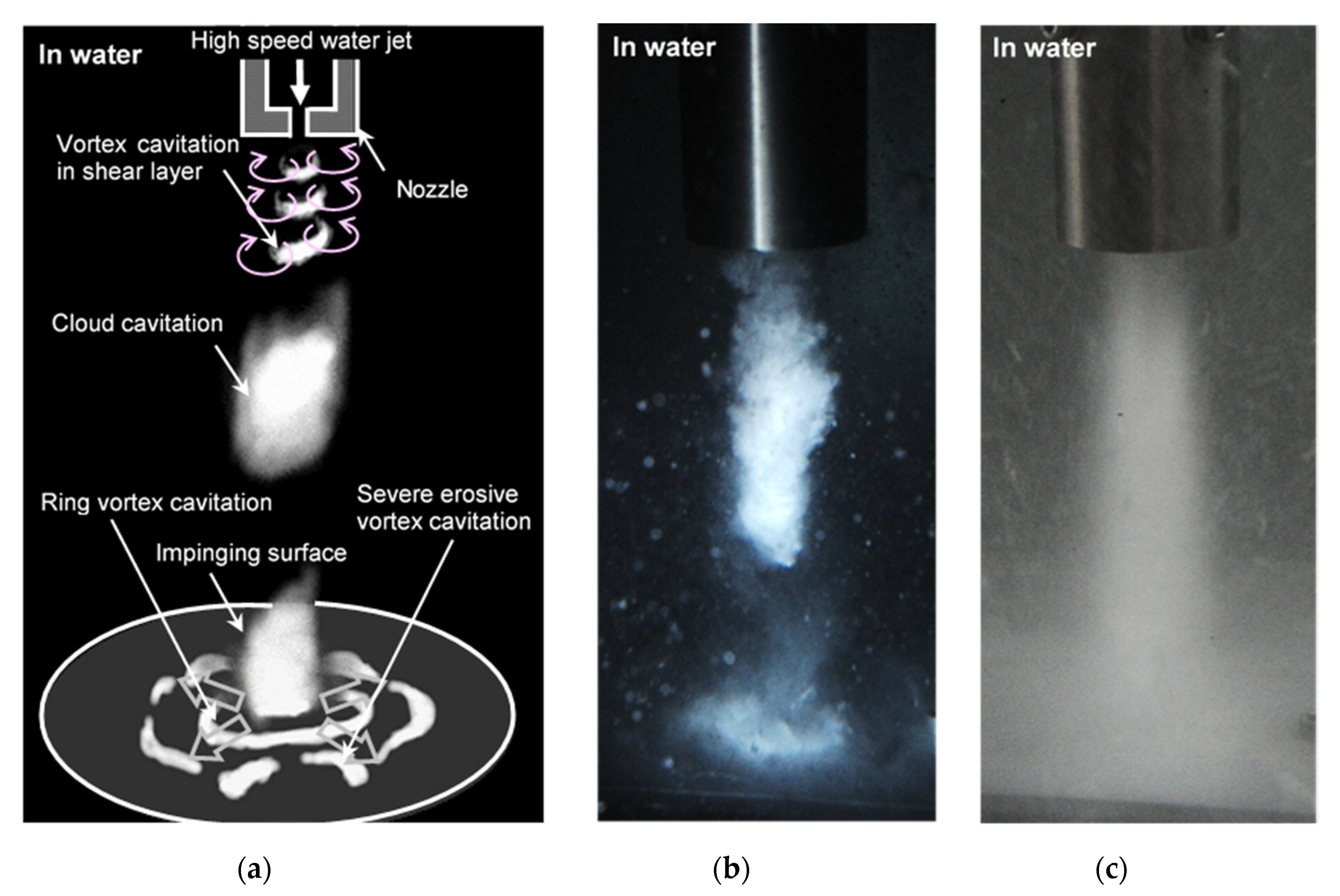
Figure 7.
Aspect of impinging cavitating jet observed by high-speed video camera.
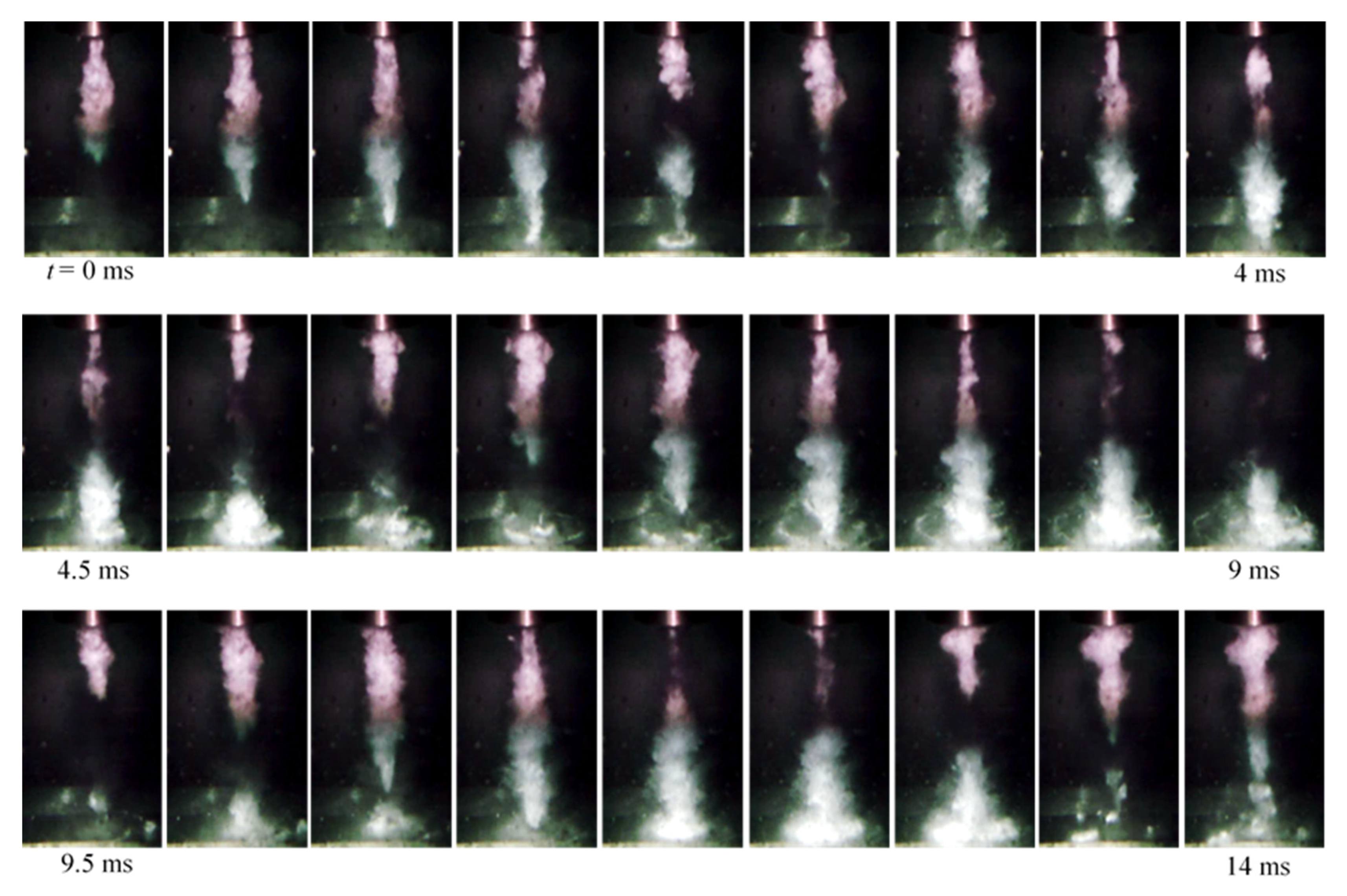
Figure 8.
Typical treatment area by a fixed cavitating jet (pure aluminum, nozzle diameter d = 2 mm, upstream pressure of nozzle p1 = 30 MPa, downstream pressure of nozzle p2 = 0.1 MPa, standoff distance s = 262 mm, exposure time t = 1 min) [3].
Figure 8.
Typical treatment area by a fixed cavitating jet (pure aluminum, nozzle diameter d = 2 mm, upstream pressure of nozzle p1 = 30 MPa, downstream pressure of nozzle p2 = 0.1 MPa, standoff distance s = 262 mm, exposure time t = 1 min) [3].
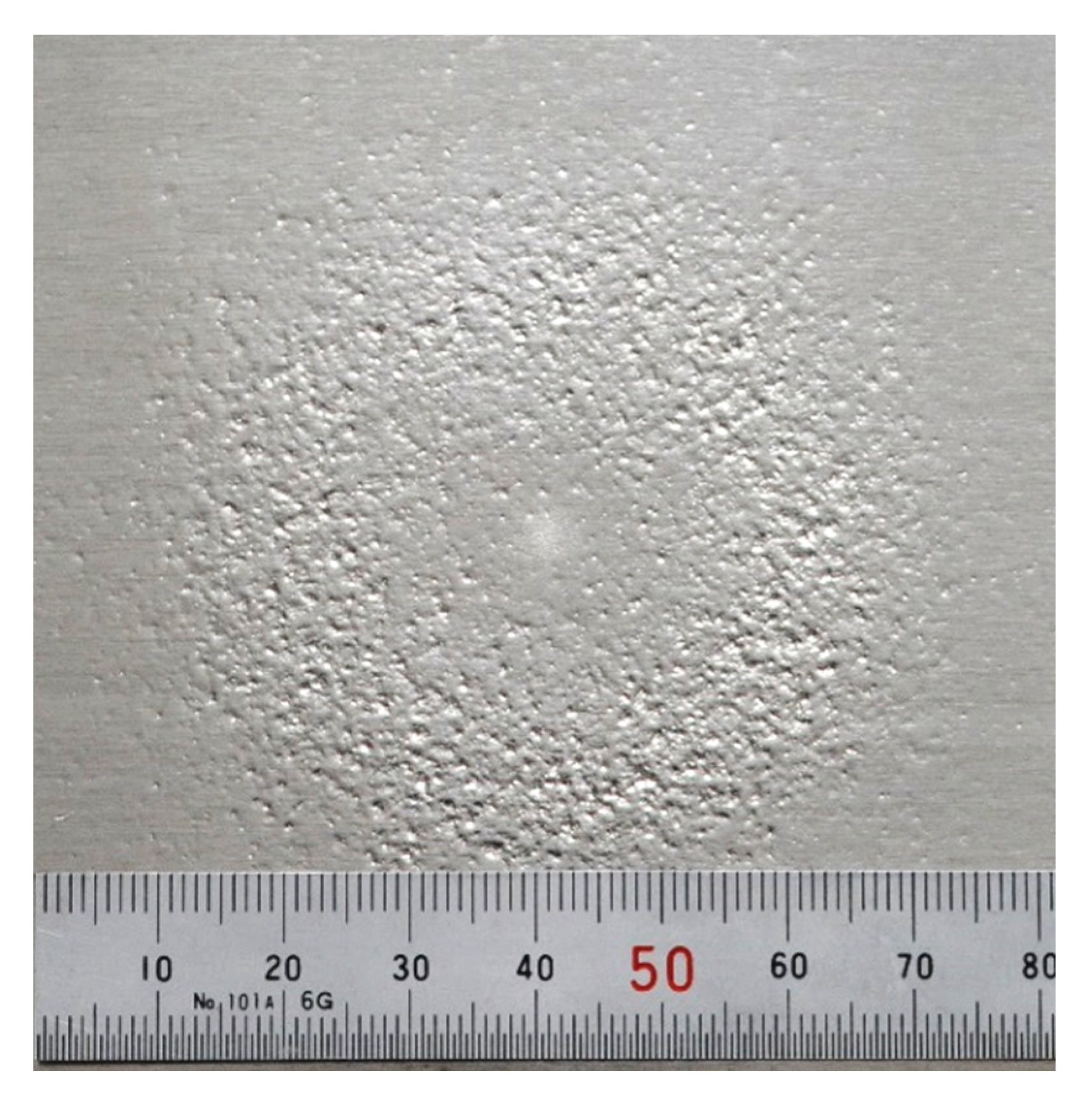
Figure 9.
Aspect of cavitating jet in water and in air [54]: (a) cavitating jet in water and (b) cavitating jet in air.
Figure 9.
Aspect of cavitating jet in water and in air [54]: (a) cavitating jet in water and (b) cavitating jet in air.
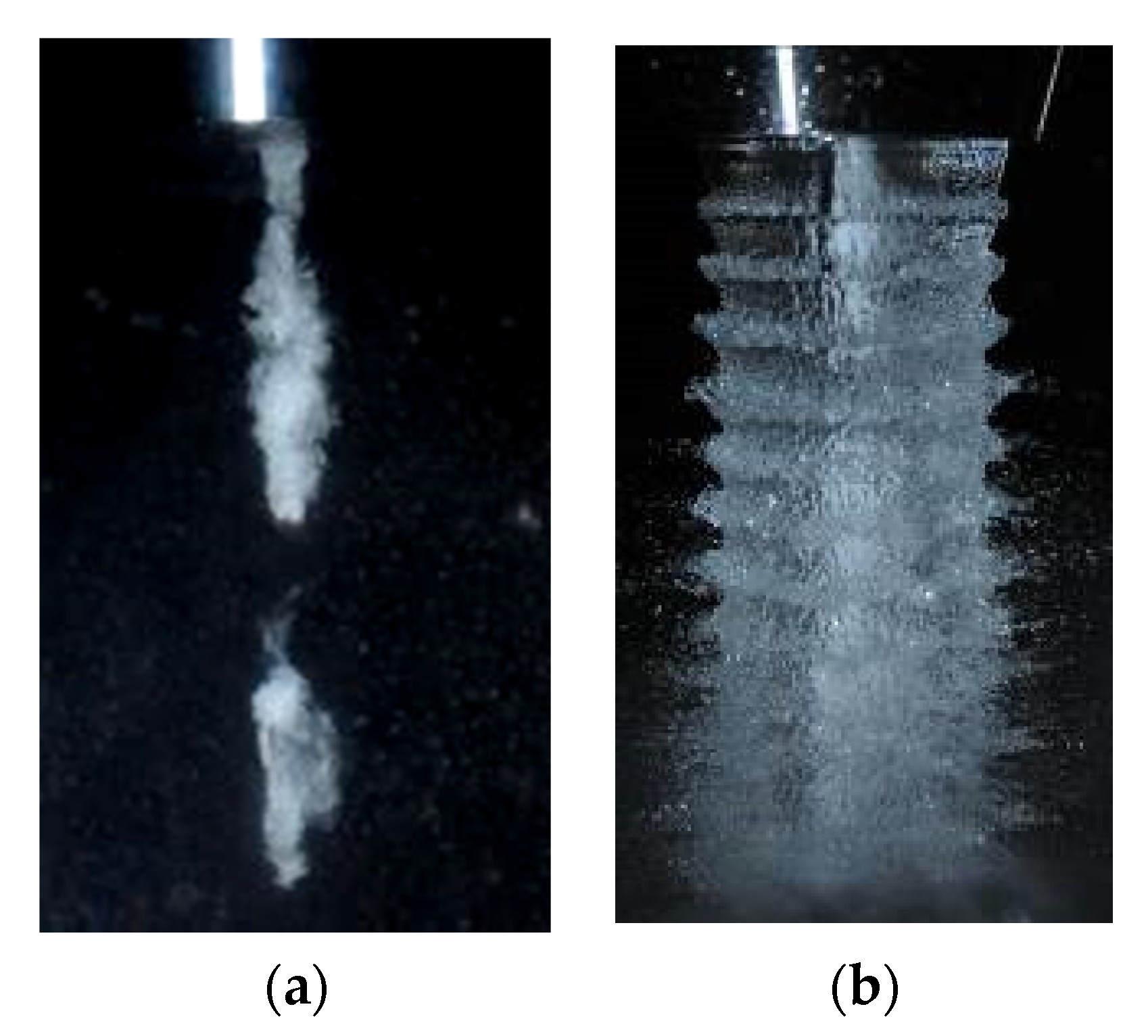
Figure 10.
Aspect of cavitation induced by vibratory apparatus [70]. Reproduced with permission from The Japan Society of Mechanical Engineers.
Figure 10.
Aspect of cavitation induced by vibratory apparatus [70]. Reproduced with permission from The Japan Society of Mechanical Engineers.
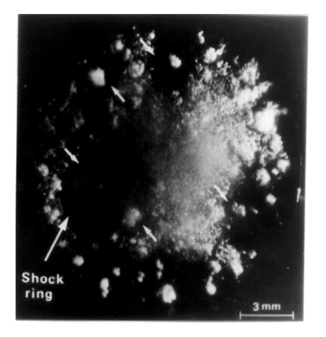
Figure 11.
Laser ablation (LA) and laser cavitation (LC) produced by a pulse laser. (a) Aspect of laser ablation (LA) and laser cavitation (LC); (b) Signal from polyvinylidene fluoride (PVDF) sensor; (c) Signal from submerged shockwave sensor.
Figure 11.
Laser ablation (LA) and laser cavitation (LC) produced by a pulse laser. (a) Aspect of laser ablation (LA) and laser cavitation (LC); (b) Signal from polyvinylidene fluoride (PVDF) sensor; (c) Signal from submerged shockwave sensor.
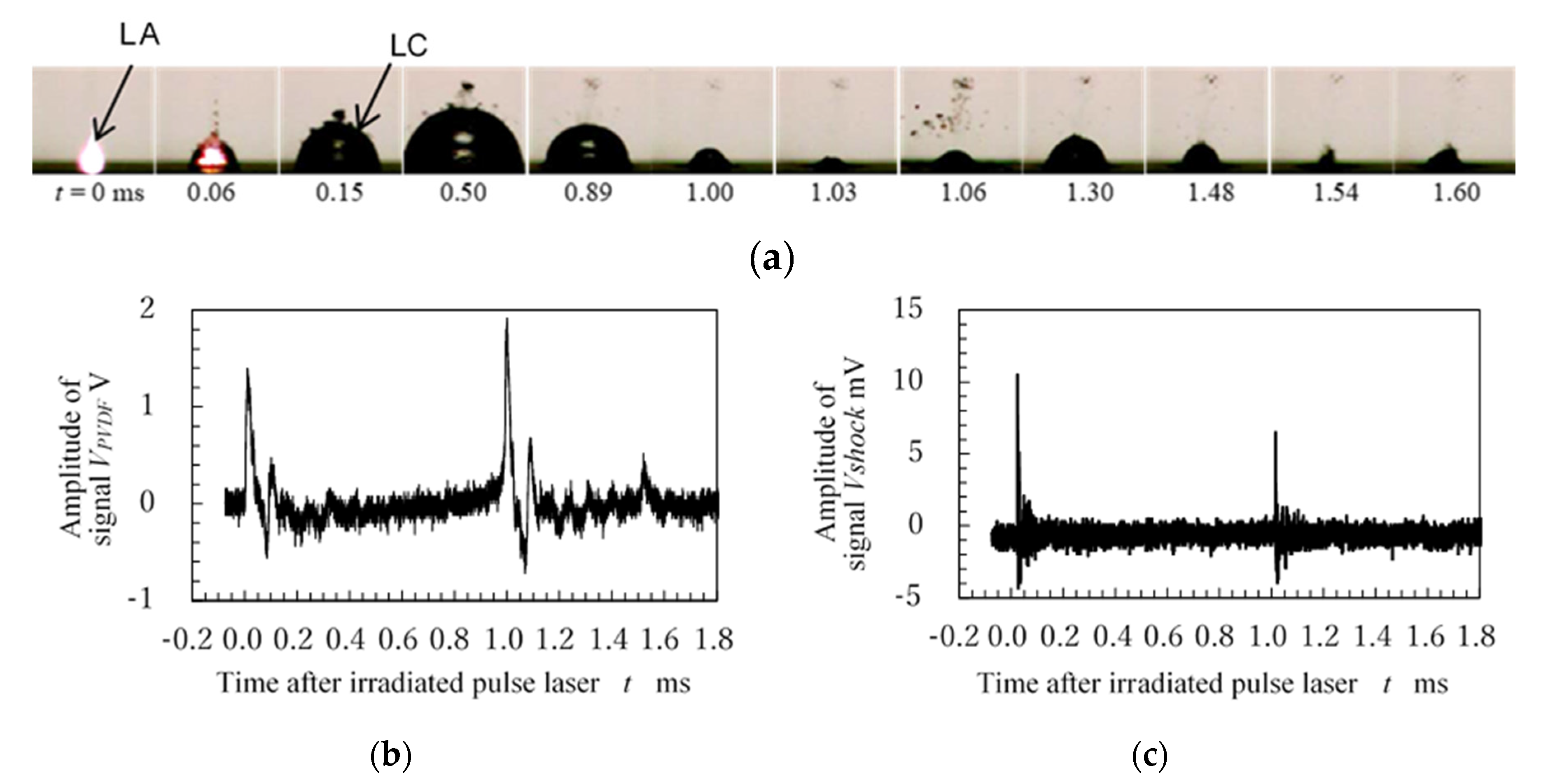
Figure 12.
Compressive residual stress introduced by several types of cavitating jets (stainless steel) [3].
Figure 12.
Compressive residual stress introduced by several types of cavitating jets (stainless steel) [3].
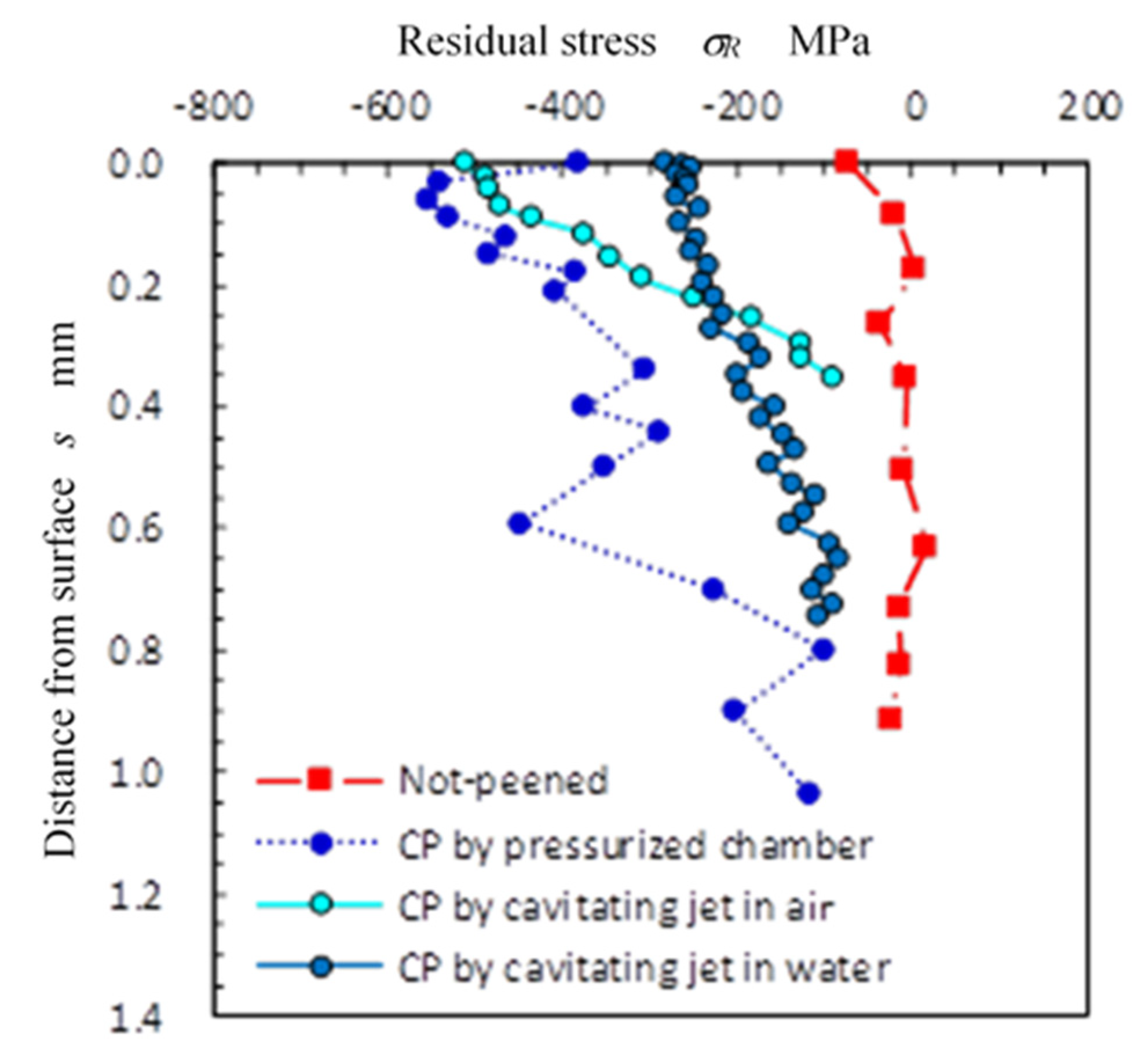
Figure 13.
Peening intensity as a function of standoff distance [97]: (a) 40 and (b) 60 MPa. Reproduced with permission from The Water Jet Technology Society of Japan.
Figure 13.
Peening intensity as a function of standoff distance [97]: (a) 40 and (b) 60 MPa. Reproduced with permission from The Water Jet Technology Society of Japan.

Figure 14.
Schematic diagram of aggressive intensity of the cavitating jet using several types of nozzles.
Figure 14.
Schematic diagram of aggressive intensity of the cavitating jet using several types of nozzles.

Figure 15.
Effect of nozzle diameter on introduction of compressive residual stress compared with non-peened (NP) (stainless steel) [100].
Figure 15.
Effect of nozzle diameter on introduction of compressive residual stress compared with non-peened (NP) (stainless steel) [100].

Figure 16.
Effect of injection pressure on introduction of compressive residual stress (stainless steel) [100].
Figure 16.
Effect of injection pressure on introduction of compressive residual stress (stainless steel) [100].
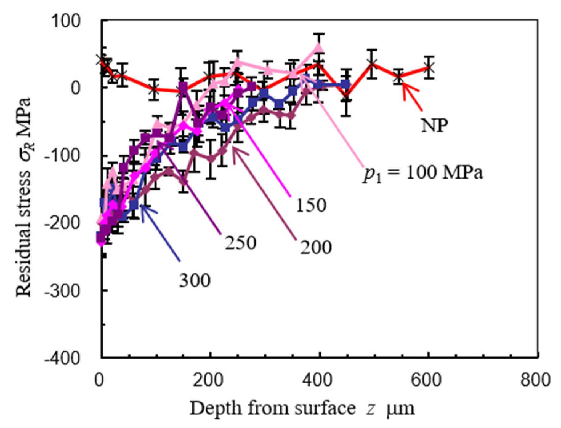
Figure 17.
Normalized aggressive intensity of a cavitating jet as a function of cavitation number [3].
Figure 17.
Normalized aggressive intensity of a cavitating jet as a function of cavitation number [3].
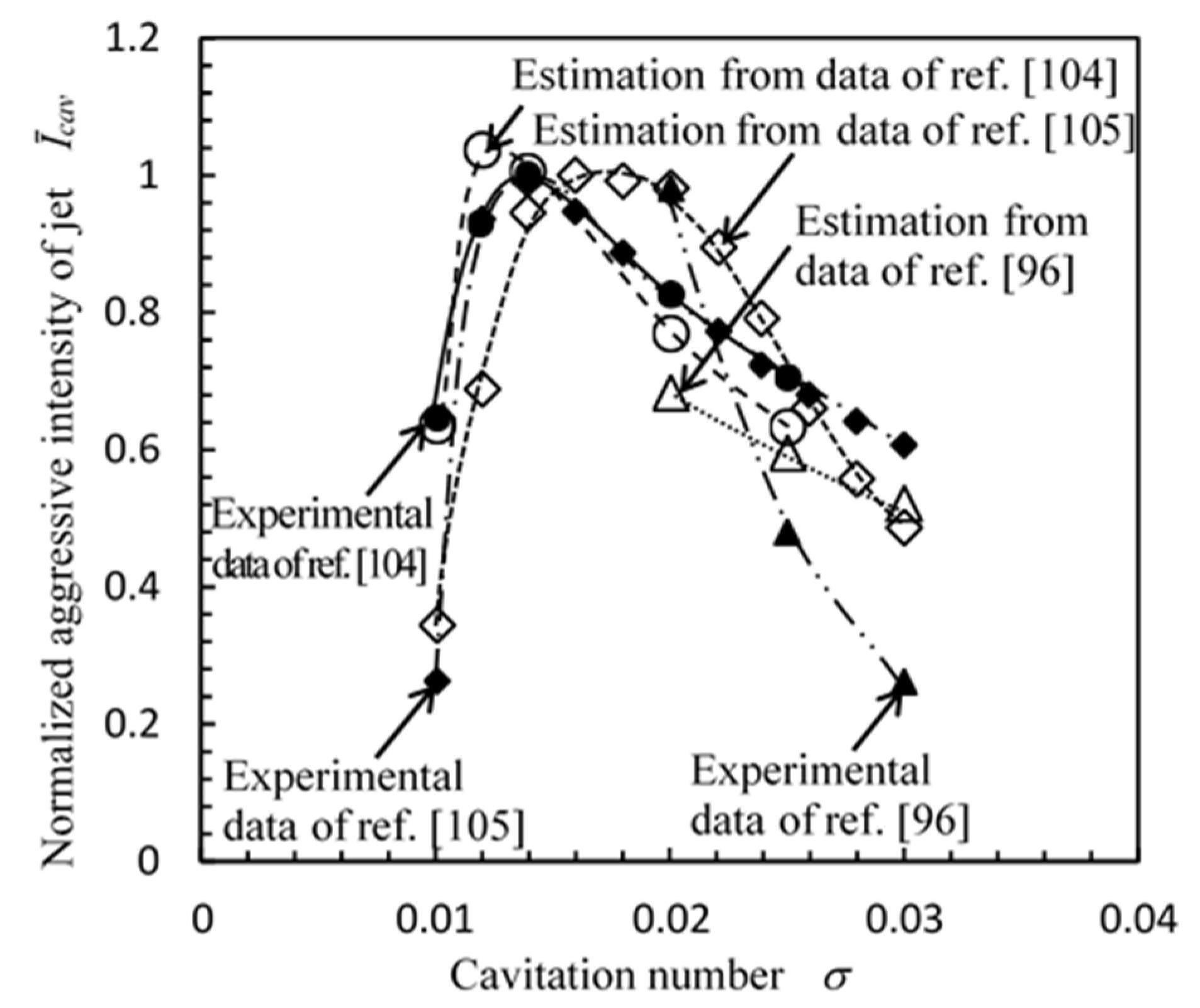
Figure 18.
Classification map for cavitation peening and water jet peening. [95]
Figure 18.
Classification map for cavitation peening and water jet peening. [95]
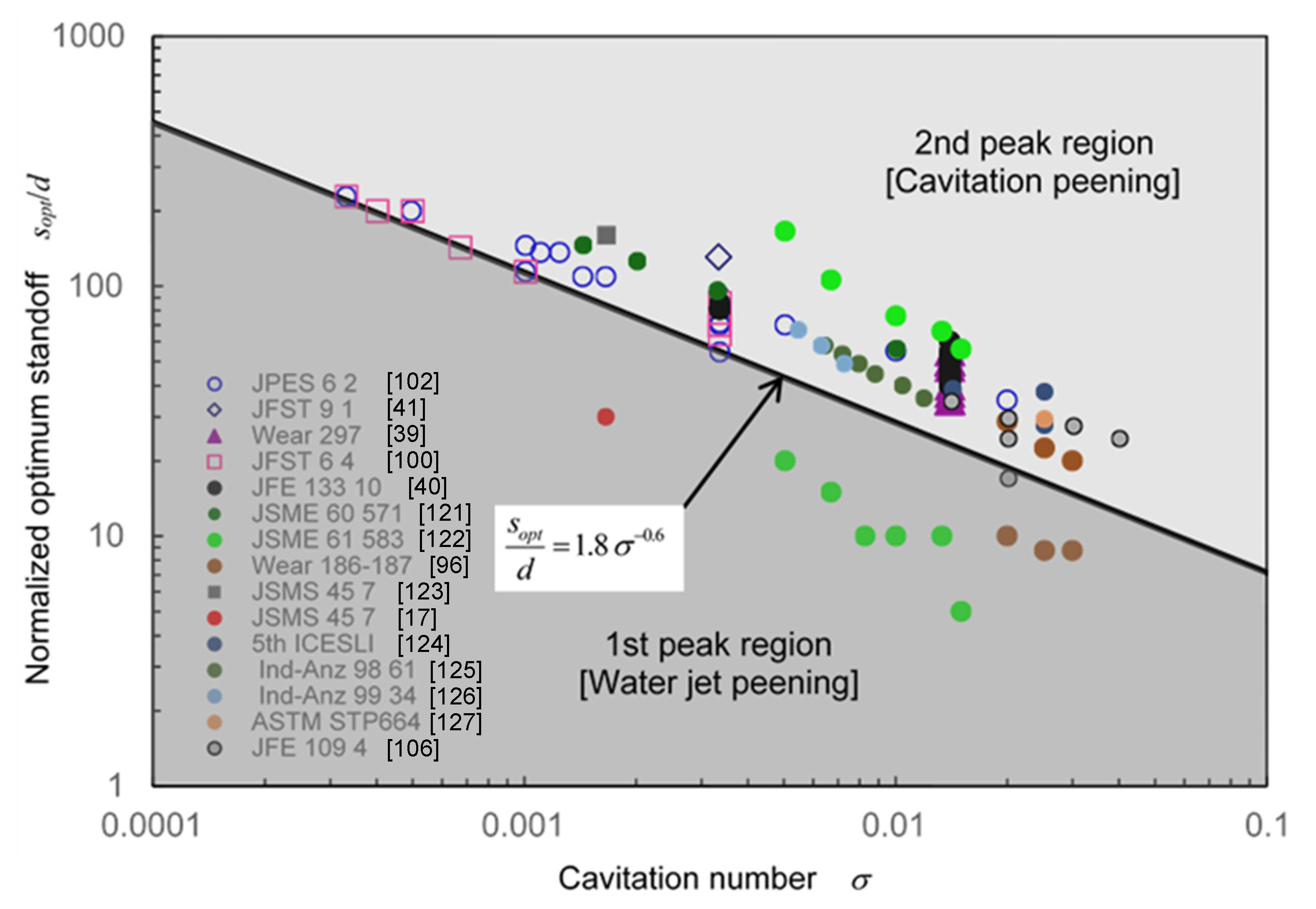
Figure 19.
Processing capability as a function of injection pressure [97]. Reproduced with permission from The Water Jet Technology Society of Japan; (a) Water jet peening; (b) Cavitation peening.
Figure 19.
Processing capability as a function of injection pressure [97]. Reproduced with permission from The Water Jet Technology Society of Japan; (a) Water jet peening; (b) Cavitation peening.
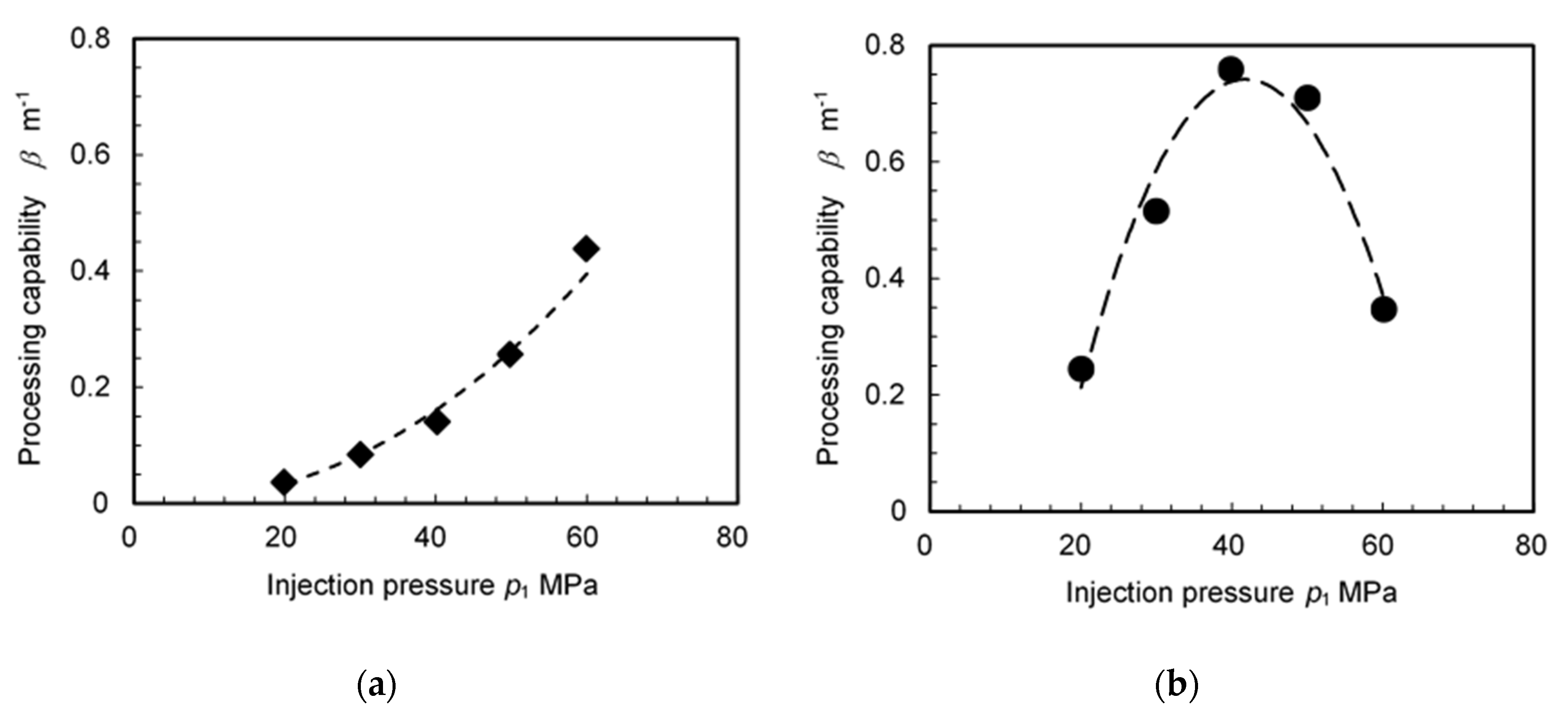
Figure 20.
Improvement in fatigue strength of stainless steel by cavitation peening (CP), shot peening (SP), laser peening (LP), and water jet peening (WJP) compared with non-peened (NP).
Figure 20.
Improvement in fatigue strength of stainless steel by cavitation peening (CP), shot peening (SP), laser peening (LP), and water jet peening (WJP) compared with non-peened (NP).
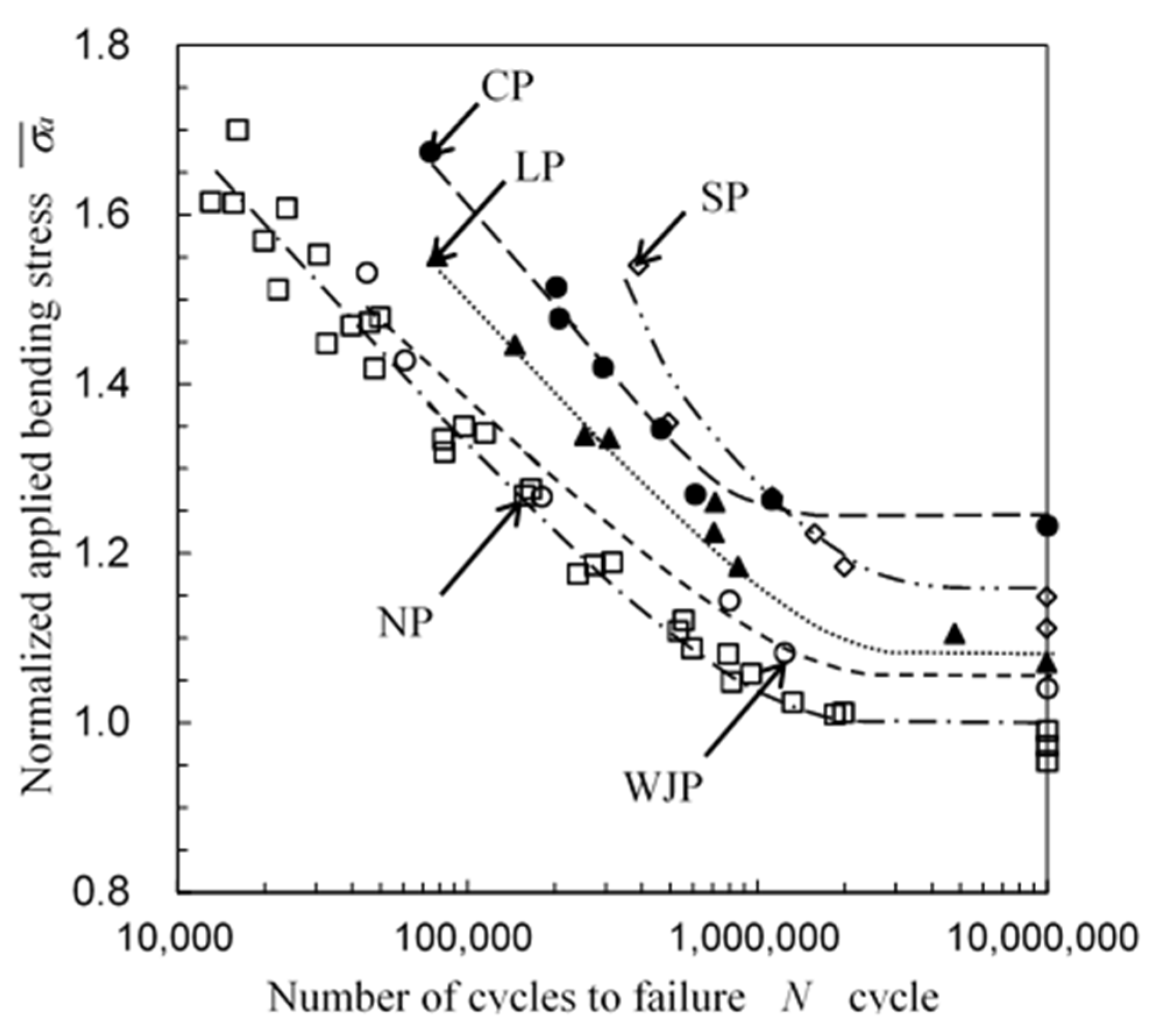
Figure 21.
Aspect of cavitating jet injecting to the gear.
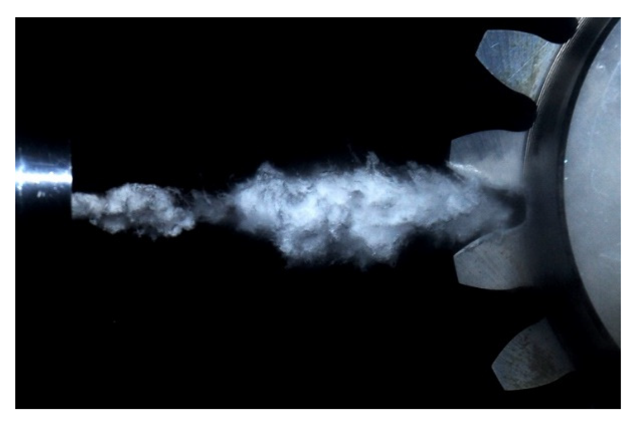
Figure 22.
Typical aspect of plastic deformation pit induced by cavitation impact in comparison with ball indentation. (a) Cavitation impact; (b) Ball indentation.
Figure 22.
Typical aspect of plastic deformation pit induced by cavitation impact in comparison with ball indentation. (a) Cavitation impact; (b) Ball indentation.


Table 1.
Colloquial terms for water jet peening [95].
Table 1.
Colloquial terms for water jet peening [95].
| Method | Mechanism of Impact | Source of Impact |
|---|---|---|
| Wet shot peening | Solid collision | Shot |
| Water jet peening | Liquid collision | Water droplet |
| Cavitation peening | Shockwave | Cavitation collapse |
© 2020 by the author. Licensee MDPI, Basel, Switzerland. This article is an open access article distributed under the terms and conditions of the Creative Commons Attribution (CC BY) license (http://creativecommons.org/licenses/by/4.0/).
Share and Cite
MDPI and ACS Style
Soyama, H. Cavitation Peening: A Review. Metals 2020, 10, 270. https://doi.org/10.3390/met10020270
AMA Style
Soyama H. Cavitation Peening: A Review. Metals. 2020; 10(2):270. https://doi.org/10.3390/met10020270
Chicago/Turabian StyleSoyama, Hitoshi. 2020. "Cavitation Peening: A Review" Metals 10, no. 2: 270. https://doi.org/10.3390/met10020270
Note that from the first issue of 2016, this journal uses article numbers instead of page numbers. See further details here.