Abstract
In this study, the effects of Cr3C2, VC, and TaC on microstructure, WC grain morphology and mechanical properties of WC–10 wt. % Co ultrafine cemented carbides were investigated. The experimental results showed that WC grains size decreased and size distribution became narrow by adding Cr3C2, VC, and TaC. The inhibition efficiency was in the order of VC > Cr3C2 > TaC. Cr3C2 addition would induce triangular prism grains and Co phase was strengthened by Cr3C2, resulting in the enhancement of transverse rupture strength (TRS) and impact toughness. WC morphologies in cemented carbides with VC addition were triangular prisms with multi-steps in basal and prismatic planes due to anisotropic growth. The multi-steps in basal and prismatic planes led to low TRS and fracture toughness. The inhibition mechanism of TaC is to reduce the surface energy of WC and slow down the solution/re-precipitation rate at the WC/Co interfaces by adsorbing on the surface of WC grains. The sample with 0.8 wt. % Cr3C2 had excellent comprehensive mechanical properties. Its Vickers hardness, fracture toughness, TRS and impact toughness were 1620 kg/mm2, 9.94 MPa·m1/2, 3960 MPa and 50.4 J/m2, respectively. In summary, Cr3C2 is the first choice as the grain growth inhibitors (GGI) for the preparation of ultrafine cemented carbides.
1. Introduction
Due to their high hardness, wear resistance and fracture strength, the WC–Co cemented carbides have been extensively used in industries, such as cutting, machining, mining, and drilling tools [1]. As the increasing cutting speed and efficiency is in great demand for cutting high performance materials, thus further improvement of their mechanical properties are urgently needed. Previous studies have shown that the mechanical properties of WC–Co cemented carbides can be substantially increased when WC grain size decreases to submicron and nanometer scale [2,3,4,5]. Till now, the most successful method to control the WC grain growth is the addition of small amounts of GGI, such as Cr3C2, VC, TaC, NbC, TiC, and so on [6,7,8]. Among various GGI, the most commonly used GGI during ultrafine cemented carbide production are Cr3C2, VC, and TaC.
It is well known that VC is more effective than Cr3C2 and TaC in inhibiting grain growth of WC but the drawback is that VC can increase the brittleness of the alloy [9]. The WC–8 wt. % Co cemented carbides with Cr3C2 addition have higher TRS and fracture toughness as compared to those with VC and TaC additions [10]. Adding TaC can improve the resistance to plastic deformation and high-temperature properties of WC–Co alloys [11,12,13]. In the last few decades, the inhibition mechanisms of Cr3C2, VC, and TaC have been extensively studied. When adding individual Cr3C2 or VC, (Cr, W)Cx or (V, W)Cx segregation layers would form on (0001)WC basal facets and {100}WC prismatic facets [14,15,16]. The segregation layers of inhibitors at WC/WC and WC/Co interface is believed to act as barriers to prevent W dissolving in liquid Co and further precipitating on WC grains [15]. Usually, the thickness of (Cr, W)Cx and (V, W)Cx segregation layers are several times higher at the (0001) habit plane than those at the (100) one and the ratio of (V, W)Cx between (0001) and (100) habit plane is higher than that of (Cr, W)Cx [14,16].However, no Ta segregation layer is observed at the WC/Co interface in cemented carbides with TaC addition [17,18] and the inhibition mechanism for TaC is still uncertain. Furthermore, studies have shown that VC induced sharp triangular grains with multi-steps [10,19,20] while Cr3C2 and TaC additions generated partly rounded WC grains [10,20,21]. Additionally, with the addition of VC, multi-steps in WC grains were deemed to cause stress concentrations on loading and increase the sensitivity to cracking, resulting in low TRS and fracture toughness [20]. So far, no systematic comparison of the effects of Cr3C2, VC, or TaC on the microstructure, WC morphology, and mechanical properties of ultrafine cemented carbides has been performed. Hence, it is worthwhile to carry out a comprehensive investigation.
In this paper, the most commonly used WC–10 wt. % Co cemented carbide is used as the target. Ultrafine WC–Co cemented carbides with the addition of 0.8 wt. % Cr3C2, VC, and TaC were prepared by conventional powder metallurgy method. The effects of Cr3C2, VC, and TaC on microstructure, WC morphology, and mechanical properties were investigated and compared to the samples without any GGI. The results may provide a scientific basis for selecting GGIs during ultrafine cemented carbide production.
2. Experimental
2.1. Materials Preparation
Ultrafine WC, Co, Cr3C2, VC, and TaC powders supplied by Zhuzhou Cemented Carbide Group Co., Ltd. (Zhuzhou, China) were used as the raw materials. The characteristics of raw materials were summarized in Table 1. The morphologies of raw materials were shown in Figure 1, which were analyzed by a scanning electron microscope (SEM, JSM–6701F, JEOL, Tokyo, Japan).

Table 1.
Characteristics of raw materials.
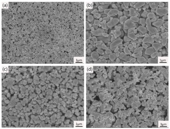
Figure 1.
Scanning electron microscope (SEM) images of (a) WC; (b) Cr3C2; (c) VC and (d) TaC raw materials.
A series of WC–10 wt. % Co cemented carbides with and without the addition of 0.8 wt. % Cr3C2, VC, and TaC were designed. The nominal composition and number of samples are shown in Table 2. The raw powder mixtures containing 2.0 wt. % paraffin were wet ball–milled for 50 h in ethanol and the ball to the powder weight ratio was 6:1. After milling and drying, the powder mixtures were pressed under a uniaxial pressure of 100 MPa and sintered at 1410 °C for 1 h under 5 MPa pressure. The final dimension of samples for transverse rupture strength test and microstructure observation was 5.25 mm × 6.5 mm × 20 mm and the final dimension of samples for impact toughness test was 5 mm × 5 mm × 50 mm.
Table 2.
Nominal composition and number of the WC–10 wt. % Co investigated cemented carbides.
2.2. Characterization
The sintered samples for microstructure observation were ground and polished by diamond pastes. The microstructure of sintered samples was analyzed by optical microscope (DM4500P, Leica, Frankfurt, Germany) and scanning electron microscopy (SEM, JSM–6701F, JEOL, Tokyo, Japan) equipped with energy dispersive spectroscopy (EDS, AZtec Energy Standard X-MaxN80X). Phase identification in the sintered samples was carried out by X–ray diffraction (XRD, D8 Advance, Karlsruhe, Germany) with copper Kα radiation. The average size and size distribution of WC grains were evaluated using electron backscattered diffraction (EBSD, Helios Nanolab 600i, FEI, Hillsboro, OR, USA) operated at 20 kV. More than 1500 grains were examined for each sample. WC grains in the sintered samples were extracted by placing samples in a saturation hydrochloric and Fe3Cl solution to remove Co binder matrix, and then the morphology of WC grains was observed by SEM. The WC/Co interfaces of sample A4 were examined by the transmission electron microscopy (TEM, FEI Titan G2 60–300, Hillsboro, OR, USA) operated at 300 kV. The local composition was measured by the energy dispersive X-ray (EDX) spectroscopy performed on the microstructures. Hardness was measured by Vicker’s hardness tester (HVS–50, Huayin Testing Instrument Co., Ltd., Laizhou, China) under a constant load of 30 kg for a dwell time of 15 s. Three hardness tests were carried out for each sample and results averaged. Fracture toughness (KIC) was calculated with the Palmqvist equation based on the crack length [22]. The TRS was measured using a three-point bending instrument (Instron3369, Norwood, MA, USA) and the impact toughness was measured by an impact toughness tester (CEAST9050, Istron, Boston, MA, USA). Six individual TRS and impact toughness measurements were performed for each sample to generate an average value.
3. Results and Discussion
3.1. Microstructure and Phase Constitution Analysis
Figure 2 presents the XRD patterns of the sintered samples with and without the addition of Cr3C2, VC, and TaC. As can be seen in Figure 2, it is clear that all the sintered samples contained only WC and Co phase, without graphite or η phase. No discernable difference can be observed among samples A1–A4 even when 0.8 wt. % Cr3C2, VC, and TaC were added. The peaks of Cr3C2, VC, and TaC were not detected may due to the low content, which was reported by some studies [10,20].
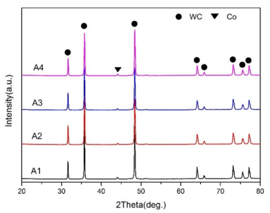
Figure 2.
X–ray diffraction (XRD) patterns of the sintered samples. A1: WC–10Co; A2: WC–10Co–0.8Cr3C2; A3: WC–10Co–0.8VC; A4: WC–10Co–0.8TaC.
Figure 3 presents the optical images of WC–10 wt. % Co sintered cemented carbides. As shown in Figure 3a, there are many coarse WC grains in sample A1 without any inhibitors addition due to abnormal grain growth (AGG), and the size of the largest WC grain even exceeds to 5 μm. Abnormal growth of WC grains cannot be detected in samples A2–A4 and their sizes distribute uniformly, indicating that Cr3C2, VC, and TaC can effectively inhibit the AGG and improve the homogeneity of WC–Co microstructure. According to Figure 3c, it is worth noting that there are many Co pools (shown by the yellow circle) in sample A3 with 0.8 wt. %VC addition while no Co pools can be obviously observed in samples A2 and A4, suggesting that VC can hinder the cobalt phase flow during liquid phase sintering. As 0.8 wt. % TaC was added, a large number of precipitates distributed heterogeneously in the microstructure and the mean size of the precipitates is about 4 μm (indicated by the white arrows), as shown in Figure 3d. In comparison with samples A3 and A4, sample A2 with 0.8 wt. % Cr3C2 addition exhibits a more uniform microstructure.
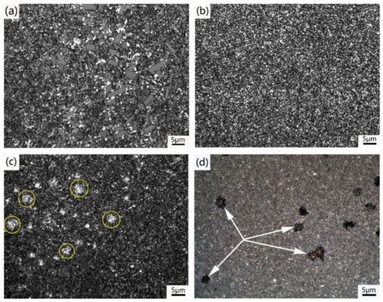
Figure 3.
Optical images showing the microstructures of sintered cemented carbides. (a) WC–10Co; (b) WC–10Co–0.8Cr3C2; (c) WC–10Co–0.8VC; (d) WC–10Co–0.8TaC.
Figure 4 shows the typical SEM images of sintered samples in the secondary electron mode. Bright contrast is WC phase and dark represent Co binder phase. It can be seen from Figure 4, compared with WC grains in sample A1, WC grains in samples A2–A4 presented obvious refinement with the addition of Cr3C2, VC, and TaC. It is worth noting that the size of WC grains in sample A3 looks further finer than that in samples A2 and A4, which indicates the inhibition efficiency of VC is higher than Cr3C2 and TaC. Additionally, among samples A2–A4, the WC grains morphology of sample A2 is more regular while the WC grains morphology of sample A3 is close to raw WC powder. EDS was used to determine the composition of the precipitates in sample A4, as shown in Figure 4d. The EDS analysis result of point B (shown in Figure 4d) indicates that the precipitates are rich in Ta, W, and C but deplete in Co. This result was in good agreement with Li et al. conclusions [23]. Li et al. [23] determined these precipitates to be (Ta, W) C phase which was formed as the amount of added TaC exceeded the saturation solubility. The non-uniform distribution of precipitates leads to the heterogeneous microstructure, which has the negative influence on mechanical properties of cemented carbides.
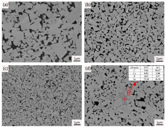
Figure 4.
SEM images showing the microstructures of WC–10 wt. % Co sintered cemented carbides. (a) WC–10Co; (b) WC–10Co–0.8Cr3C2; (c) WC–10Co–0.8VC; (d) WC–10Co–0.8TaC.
EDS was used to further analysis the distribution of Cr3C2, VC, and TaC in the sintered cemented carbides. Figure 5, Figure 6 and Figure 7 show the EDS elemental mapping of samples A2, A3 and A4, respectively. For convenience, the analysis was carried out at different magnification times. From Figure 5, Figure 6 and Figure 7, there are significant differences for Cr3C2, VC, and TaC distribution among samples A2–A4. As can be seen in Figure 5, no precipitates was formed in sample A2 and Cr was dissolved in Co binder phase. However, there were some precipitates observed in samples A3 and A4, as shown in Figure 6 and Figure 7. The explanation for this phenomenon could be that the solubility of Cr3C2 in Co phase is higher than that of VC and TaC [24,25,26], and the solubility of VC and TaC in Co phase is less than 0.8 wt. %. Studies have shown that dissolved GGI will precipitate out when the amount of added inhibitors is over the maximum solubility [23,25,27,28]. EDS analysis results indicate the precipitates formed in A3 are rich in V, W, and C, but deplete in Co, which can be deduced to be (V, W) C cubic phase. The precipitates in A4 are (Ta, W) C cubic phase, and the analysis result can be seen in Figure 4. No diffraction peaks of (V, W) C and (Ta, W) C phases were detected in the XRD patterns can be attributed to their low content. The sizes of (V, W) C and (Ta, W) C grains reach 5~10 μm, which is much higher than that of the raw powder. (V, W) C and (Ta, W) C grains are formed and grown via dissolution/re-precipitation mechanism, the driving force of the dissolution/re-precipitation is the reduction in the total free energy of the system [29]. In addition, Figure 6 confirms that there are a large number of cobalt pools in sample A3, agreeing well with metallographic analysis results in Figure 3c.
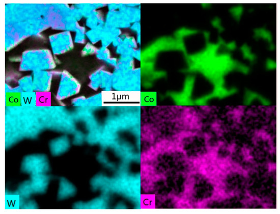
Figure 5.
Energy dispersive spectroscopy (EDS) elemental mapping of sample A2 with 0.8 wt. % Cr3C2.
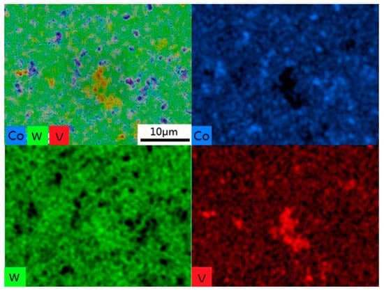
Figure 6.
EDS elemental mapping of sample A3 with 0.8 wt. % VC.
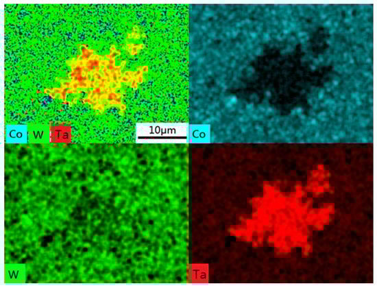
Figure 7.
EDS elemental mapping of sample A4 with 0.8 wt. % TaC.
Figure 8 shows the IPF (inverse pole figure) colored EBSD maps of WC–10 wt. % Co sintered samples, in which the colors correspond to the crystal orientations of WC grains. Figure 9 presents the measured average size and size distribution of WC grains in WC–10 wt. % Co sintered cemented carbides based on EBSD maps of Figure 8. It is clear to see that the average size decreases significantly and the size distribution becomes narrow by adding Cr3C2, VC, and TaC. As shown in Figure 9a, the grain size in sample A1 without any inhibitor addition is from 0.7 μm to 3.0 μm, and the average WC grain size is 0.97 μm. With the addition of Cr3C2, VC, and TaC, the average grain size of samples A2, A3, and A4 reduces to 0.36, 0.24, and 0.41 μm, respectively. Compared to sample A1, the average grain sizes of samples A2, A3, and A4 reduce by 63%, 75%, and 58%, respectively, indicating the inhibition efficiency is in the order of VC > Cr3C2 > TaC [30]. In contrast to a wide WC grain size distribution of sample A1, samples A2, A3, and A4 show a narrow WC grain size distribution. The WC grain size in samples A2, A3, and A4 range from 0.2 μm to 0.9 μm, 0.1 μm to 0.7 μm, and 0.3 μm to 1.1 μm, respectively. Compared to samples A2 and A4, sample A3 shows a relatively narrower WC grain size distribution may due to the high inhibition efficiency of VC. These results are consistent with the result from SEM examination in Figure 4.
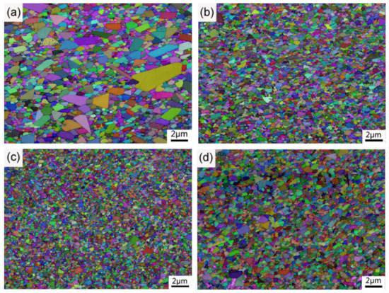
Figure 8.
Electron backscattered diffraction (EBSD) maps in inverse pole figure colors, in which the colors correspond to the crystal orientations of WC grains, for the WC–10 wt. % Co investigated cemented carbides sintered at 1410 °C for 1 h. (a) WC–10Co; (b) WC–10Co–0.8Cr3C2; (c) WC–10Co–0.8VC; (d) WC–10Co–0.8TaC.
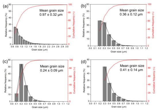
Figure 9.
Average size and size distribution of WC grains in WC-10 wt. % Co sintered cemented carbides. (a) WC–10Co; (b) WC–10Co–0.8Cr3C2; (c) WC–10Co–0.8VC; (d) WC–10Co–0.8TaC.
3.2. Effect of VC, Cr3C2, TaC on WC Morphology
Figure 10 shows the WC grain morphology of WC–10 wt. % Co sintered cemented carbides with the Co phase removed. As can be seen from Figure 10a for sample A1, without any addition, the WC grains present a truncated multangular prism feature with more than eight crystal planes, which indicates that WC morphology is close to the equilibrium shape [31,32]. This result is consistent with the report of Zhang et al. [33]. When adding 0.8 wt. % Cr3C2, the WC grains exhibit a triangular prism shape, as shown in Figure 10b. As 0.8 wt. % VC added, the morphologies of WC grains are triangular prisms with multi-steps in basal and prismatic planes, which are clearly the product of anisotropic growth, as shown in Figure 10c. However, the morphologies of WC grains are near truncated triangular prisms by adding 0.8 wt. % TaC, as shown in Figure 10d. From the comparison, it is evident that Cr3C2, VC, and TaC exert a considerable influence on WC grains growth during sintering.
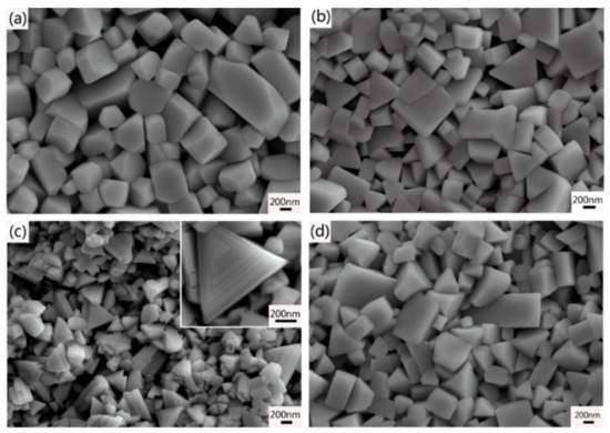
Figure 10.
Morphology of WC grains extracted from the WC-10 wt. % Co sintered cemented carbides. (a) WC–10Co; (b) WC–10Co–0.8Cr3C2; (c) WC–10Co–0.8VC; (d) WC–10Co–0.8TaC.
As well known, the equilibrium shape of WC is a truncated triangular prism rather than round morphology [32,34]. The WC grains distributed in the Co phase usually generate three types of facets: two types of prismatic {100} facets and two basal (0001) facets that delimit the flat triangular prism with truncated corners [35]. Schematic of the equilibrium shape for a WC grain is shown in Figure 11a. Studies have shown that the morphology of WC grains in WC–Co cemented carbides depends strongly on the difference in interfacial energy [34,36,37] and in growth rate [38,39] among the facets. The morphologies of triangular prisms and triangular prisms with multi-steps in basal and prismatic planes can obviously attribute to anisotropic growth. The anisotropic coarsening of WC grains is mainly controlled via the 2-D nucleation and growth mechanism [40,41]. With the addition of Cr3C2, Cr segregates at (0001) basal facets and {100} prismatic facets of WC grains as (Cr, W) Cx carbide [16]. The (Cr, W)Cx segregation layers would reduce surface energies and improve the energy barrier for 2-D nucleation and growth. Therefore, the growth rate of (0001) basal and {100} prismatic facets is inhibited and the {100} prismatic facets grow preferentially or more rapidly. After sintering at 1410 °C for 1 h, the three–dimensional morphology of WC grains transforms to regular triangular prism, as illustrated in Figure 11b. Similarly, (V, W) Cx segregation layers would also be formed at (0001) basal facets and {100} prismatic facets of WC grains in the cemented carbides with VC [14,16]. However, the concentration ratios of (V, W) Cx at the (0001) habit plane to the ones at the (100) habit plane is several times higher than that of (Cr, W) Cx [14,16]. Consequently, there exists considerable difference in energy and growth rate among the facets [32]. Therefore, grain growth along [0001] direction is effectively suppressed and WC grains are stacked along [0001] direction to form multi-steps based on (0001) basal planes [10,20]. The schematic diagram of a WC grain in the cemented carbides with 0.8 wt. %VC is shown in Figure 11c.
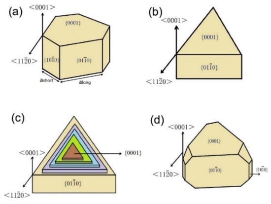
Figure 11.
Schematic of (a) equilibrium shape of WC grain in Co binder and three–dimensional morphology of WC grains in (b) WC–10Co–0.8Cr3C2; (c) WC–10Co–0.8VC; (d) WC–10Co–0.8TaC.
The WC grains in sample A4 with 0.8 wt. %TaC addition exhibit a near truncated triangular prism shape, which indicates that the difference of growth rate among the facets is small. Thereby, it is reasonable to conclude that the distribution of TaC at WC/Co interface is different from that of Cr3C2 and VC. In order to verify this conclusion, the WC/Co interface of sample A4 was studied by TEM. TEM studies of the basal (0001)WC WC/Co interface doped with Ta (sample A4) is shown in Figure 12. High–resolution energy dispersive X–ray (HREDX) elemental mapping shown in Figure 12b–d indicates that no obvious Ta segregation layer can be observed in basal (0001)WC WC/Co interface and Ta is adsorbed in the WC grain surface. As the TEM studies of the prismatic (100)wc WC/Co interface have obtained the same results with basal (0001)WC WC/Co interface, the results are not shown. It is reasonable to conclude that the grain growth inhibition mechanism of TaC is to reduce the surface energy of WC and slow down the solution/re-precipitation rate at the WC/Co interfaces by adsorbing on the surface of WC grains. Therefore, the anisotropic growth in sample A4 is not obvious due to the small difference of interface energy and growth rate among the facets, which leads to near truncated triangular prism morphology.
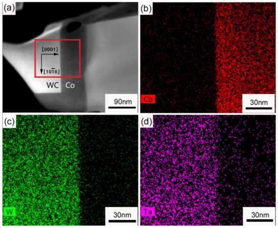
Figure 12.
TEM studies of the basal (0001)WC WC/Co interface in sample A4 with 0.8 wt. % TaC. (a) High–angle annular dark field (HAADF) image of basal (0001)WC WC/Co interface. (b–d) High–resolution energy dispersive X–ray (HREDX) elemental mapping of Co, W, and Ta of the region of (a), respectively.
3.3. Mechanical Properties and Fracture Morphology
Figure 13 shows the mechanical properties of WC–10 wt. % Co cemented carbides sintered at 1410 °C. Hardness and fracture toughness are two most important mechanical properties of the cemented carbides. As shown in Figure 13a, the hardness increases while the fracture toughness decreases by adding GGI. With the addition of Cr3C2, VC, and TaC, the hardness of samples A2–A4 increases from 1440 kg/mm2 to 1620 kg/mm2, 1740 kg/mm2, and 1560 kg/mm2, as well as increases by 12.5%, 20.8%, and 8.3%, respectively, which is in good accordance with the inhibition efficiency order of VC > Cr3C2 > TaC [30]. As well known, the hardness is improved as the WC grain size decreased according to the Hall–Petch relation [42]. Correspondingly, sample A3 has the highest hardness of 1740 kg/mm2 due to the smallest grain size of 0.24 μm (as shown in Figure 9).
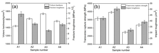
Figure 13.
Mechanical properties of WC–10 wt. % Co sintered samples. (a) Vickers hardness and fracture toughness; (b) transverse rupture strength and impact toughness. A1: WC–10Co; A2: WC–10Co–0.8Cr3C2; A3: WC–10Co–0.8VC; A4: WC–10Co–0.8TaC.
From Figure 13a, it is easy to see that there exists an inverse relationship between hardness and fracture toughness. With the addition of Cr3C2, VC, and TaC, the fracture toughness decreases from 11.88 MPa·m1/2 to 9.94 MPa·m1/2, 8.79 MPa·m1/2, and 9.79 MPa·m1/2, respectively. It is worth mentioning that the hardness of sample A2 is higher than sample A4, while the fracture toughness of sample A2 is also slightly higher than that of sample A4. The explanation for this phenomenon could be that a small amount of (Ta, W) C grains form and distribute non-uniformly in the microstructure. On the one hand, (Ta, W) C cubic phase is a brittle phase with a low strength [11]. On the other hand, the strength between (Ta, W) C and Co phase is low due to its poor wettability by the Co binder phase. What’s more, the size of (Ta, W) C grains (~4 μm) is much higher than that of WC grains, resulting in the heterogeneous microstructure. Compared to Cr3C2 and VC additions, TaC addition neither provides high fracture toughness nor significantly improves hardness. In a word, the fracture toughness of alloys is mainly dependent upon the WC grain size when Co content keeps constant. The smaller the grain size of sintered samples, the lower the fracture toughness of sintered samples. Moreover, a non-uniform microstructure will also reduce the fracture toughness of cemented carbides.
Figure 13b shows TRS and impact toughness of sintered samples A1–A4. For sample A1 without any addition, TRS is 3570 MPa. After adding 0.8 wt. % Cr3C2, TRS of sample A2 improves to 3960 MPa and improves by 11%. The significant improvement of TRS is a comprehensive outcome of grain refinement, a more uniform microstructure, triangular prism shape of WC grains and strengthened Co binder phase by Cr3C2 [43]. However, with the addition of 0.8 wt. %VC, the TRS of sample A3 decreases sharply to 2740 MPa and decreases by 23% compared to sample A1. This result can be explained by the following three aspects: (1) the precipitates of (V, W) C formed in the cemented carbides is a brittle phase and has low strength with Co phase; (2) (V, W) Cx segregation layers forming at the WC/Co interface reduce the interface energy of WC/Co, leading to the low separation energies [20]; (3) multi-steps in WC grains cause stress concentration and increase fracture sensitivity [44]. As 0.8 wt. %TaC added, TRS of sample A4 even decreases in despite of significant grain refinement. The explanation for this phenomenon could be that some coarse (Ta, W) C grains forming in the cemented carbides lead to the heterogeneous microstructure and deteriorate TRS. It is obvious that there exists a synergetic correlation between TRS and impact toughness. Similarly, impact toughness is improved by adding Cr3C2 while reduced as VC and TaC are added. Among samples A2–A4, sample A2 has the highest impact toughness of 50.4 J/m2, followed by sample A4 of 39.2 J/m2 and sample A3 of 32.3 J/m2. It is reasonable to conclude that TRS and impact toughness are strongly dependent upon addition inhibitors, grain size and morphologies of WC grains. Therefore, it is important to optimize WC grain size and control the three-dimensional morphology of WC grains by selecting GGI reasonably. As a whole, sample A2 with 0.8 wt. % Cr3C2 addition has excellent comprehensive mechanical properties, compared to the other samples. Its Vickers hardness, fracture toughness, TRS, and impact toughness were 1620 kg/mm2, 9.94 MPa·m1/2, 3960 MPa, and 50.4 J/m2, respectively. In summary, Cr3C2 was the first choice as the GGI for preparation of ultrafine cemented carbide.
Figure 14 presents the fracture surface morphologies of sintered samples A1–A4. The fracture mode can be observed as transgranular fracture and intergranular fracture, with obvious cleavage and dimple characters in the SEM images. According to Figure 14a, the fracture analyses reveal that the transgranular fracture occurred due to coarse WC grains. Compared to the fine grains, coarse grains bear a greater stiffness, which leads to the earlier rupture under the same stress. With the addition of GGI, transgranular fracture decreases significantly while intergranular fracture becomes predominant due to the decrease of WC grain size, as shown in Figure 14b–d. In addition, coarse (V, W) C and (Ta, W) C grains formed in WC–10 wt. % Co cemented carbides would induce transgranular fracture due to its high brittleness and low strength.
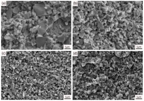
Figure 14.
The fracture surface morphologies of WC–10 wt. % Co sintered cemented carbides. (a) WC–10Co; (b) WC–10Co–0.8Cr3C2; (c) WC–10Co–0.8VC; (d) WC–10Co–0.8TaC.
4. Conclusions
(1) With the addition of Cr3C2, VC, and TaC, the size of WC grains decreases and the size distribution becomes narrow, the hardness increases while the fracture toughness decreases. The inhibition efficiency is in the order of VC > Cr3C2 > TaC.
(2) The morphology of WC grains in WC–10 wt. % Co cemented carbides with Cr3C2 addition is triangular prism and Co phase is strengthened by Cr3C2, resulting in the enhancement of TRS. VC addition would induce triangular prism grains with multi–steps in basal and prismatic planes due to anisotropic growth, leading to low TRS and fracture toughness.
(3) No Ta segregation layer form at WC/Co interface, and the inhibition mechanism of TaC is to reduce the surface energy of WC and slow down the solution/re–precipitation rate at the WC/Co interfaces by adsorbing on the surface of WC grains. A small amount of (Ta, W) C grains form in sample A4 as 0.8 wt. % TaC added. This phase would decrease the TRS of cemented carbides due to its poor wettability by the Co binder.
(4) The sample with 0.8 wt. % Cr3C2 addition has excellent comprehensive mechanical properties. Its Vickers hardness, fracture toughness, TRS, and impact toughness are 1620 kg/mm2, 9.94 MPa·m1/2, 3960 MPa, and 50.4 J/m2, respectively. In summary, Cr3C2 is the first choice as the GGI for preparation of ultrafine cemented carbide.
Author Contributions
Conceptualization, C.Y., J.R. and Y.D.; data curation, C.Y. and Y.D.; formal analysis, C.Y., J.R. and Y.D.; investigation, C.Y., J.R., Y.D., Y.P. and J.L.; methodology, J.R. and Y.P.; writing—original draft, C.Y. and J.L.; writing—review & editing, Y.P. and K.L. All authors have read and agreed to the published version of the manuscript.
Funding
This work is supported by the Hunan Provincial Natural Science Foundation of China (Grant No. 2019JJ60007), Special Funds for the Construction of Hunan Innovation Province (Grant No. 2019GK2052) and Sciences Platform Environment and Capacity Building Projects of GDAS (No. 2019GDASYL-0502006).
Conflicts of Interest
The authors declare no conflict of interest.
References
- Farag, S.; Konyashin, I.; Ries, B. The influence of grain growth inhibitors on the microstructure and properties of submicron, ultrafine and nano-structured hardmetals—A review. Int. J. Refract. Met. Hard Mater. 2018, 77, 12–30. [Google Scholar] [CrossRef]
- Liu, K.; Wang, Z.; Yin, Z.; Cao, L.; Yuan, J. Effect of Co content on microstructure and mechanical properties of ultrafine grained WC–Co cemented carbide sintered by spark plasma sintering. Ceram. Int. 2018, 44, 18711–18718. [Google Scholar] [CrossRef]
- Garcia, J.; Cipres, V.C.; Blomqvist, A.; Kaplan, B. Cemented carbide microstructures: A review. Int. J. Refract. Met. Hard Mater. 2019, 80, 40–68. [Google Scholar] [CrossRef]
- Fukatsu, T.; Kobori, K.; Ueki, M. Micro-grained cemented carbide with high strength. Int. J. Refract. Met. Hard Mater. 1991, 10, 57–60. [Google Scholar] [CrossRef]
- Zhao, S.X.; Song, X.Y.; Zhang, J.X.; Liu, X. Effects of scale combination and contact condition of raw powders on SPS sintered near-nanocrystalline WC–Co alloy. Mater. Sci. Eng. A 2008, 473, 323–329. [Google Scholar] [CrossRef]
- Weidow, J.; Andrén, H.O. Binder phase grain size in WC–Co–based cemented carbides. Scr. Mater. 2010, 63, 1165–1168. [Google Scholar] [CrossRef]
- Bonache, V.; Salvador, M.D.; Rocha, V.G.; Borrell, A. Microstructural control of ultrafine and nanocrystalline WC–12Co–VC/Cr3C2 mixture by spark plasma sintering. Ceram. Int. 2011, 37, 1139–1142. [Google Scholar] [CrossRef]
- Huang, S.G.; Li, L.; Vanmeensel, K.; Van der Biest, O.; Vleugels, J. VC, Cr3C2 and NbC doped WC–Co cemented carbides prepared by pulsed electric current sintering. Int. J. Refract. Met. Hard Mater. 2007, 25, 417–422. [Google Scholar] [CrossRef]
- Sun, L.; Jia, C.; Xiong, J. VC, Cr3C2 doped ultrafine WC–Co cemented carbides prepared by spark plasma sintering. Int. J. Refract. Met. Hard Mater. 2011, 29, 147–152. [Google Scholar] [CrossRef]
- Wang, B.; Wang, Z.; Yin, Z.; Yuan, J.; Jia, J. Preparation and properties of the VC/Cr3C2/TaC doped ultrafine WC–Co tool material by spark plasma sintering. J. Alloys Compd. 2020, 816, 152598. [Google Scholar] [CrossRef]
- Östberg, G.; Buss, K.; Christensen, M.; Norgren, S.; Andrén, H.O.; Mari, D.; Wahnström, G.; Reineck, I. Effect of TaC on plastic deformation of WC–Co and Ti(C,N)–WC–Co. Int. J. Refract. Met. Hard Mater. 2006, 24, 145–154. [Google Scholar] [CrossRef]
- Merwe, R.; Sacks, N. Effect of TaC and TiC on the Friction and Dry Sliding Wear of WC–6 wt.% Co Cemented Carbides Against Steel Counterfaces. Int. J. Refract. Met. Hard Mater. 2013, 41, 94–102. [Google Scholar] [CrossRef]
- Wu, P.; Zheng, Y.; Zhao, Y.L.; Yu, H. Effect of TaC Addition on the Microstructures and Mechanical Properties of Ti(C, N)-Based Cermets. Mater. Design. 2010, 31, 3537–3541. [Google Scholar] [CrossRef]
- Yamamoto, T.; Ikuhara, Y.; Sakuma, T. High resolution transmission electron microscopy study in VC-doped WC–Co compound. Sci. Technol. Adv. Mater. 2001, 1, 97–104. [Google Scholar] [CrossRef]
- Yamamoto, T.; Ikuhara, Y.; Watanabe, T.; Sakuma, T.; Taniuchi, Y.; Okada, K.; Tanase, T. High resolution microscopy study in Cr3C2-doped WC−Co. J. Mater. Sci. 2001, 36, 3885–3890. [Google Scholar] [CrossRef]
- Kawakami, M.; Kitamura, K. Segregation layers of grain growth inhibitors at WC/WC interfaces in VC-doped submicron-grained WC–Co cemented carbides. Int. J. Refract. Met. Hard Mater. 2015, 52, 229–234. [Google Scholar] [CrossRef]
- Kawakami, M.; Terada, O.; Hayashi, K. HRTEM microstructure and segregation amount of dopants at WC/Co interfaces in TiC and TaC mono-doped WC–Co submicro-grained hardmetals. J. Jpn. Soc. Powder Metall. 2006, 53, 166–171. [Google Scholar] [CrossRef]
- Weidow, J.; Andrén, H.O. Grain and phase boundary segregation in WC–Co with TiC, ZrC, NbC or TaC additions. Int. J. Refract. Met. Hard Mater. 2011, 29, 38–43. [Google Scholar] [CrossRef]
- Lee, H.R.; Kim, D.J.; Hwang, N.M.; Kim, D.Y. Role of vanadium carbide additive during sintering of WC–Co: Mechanism of grain growth inhibition. J. Am. Ceram. Soc. 2004, 86, 152–154. [Google Scholar] [CrossRef]
- Chen, H.; Yang, Q.; Yang, J.; Yang, H.; Chen, L.; Ruan, J.; Huang, Q. Effects of VC/Cr3C2 on WC grain morphologies and mechanical properties of WC–6 wt. % Co cemented carbides. J. Alloys Compd. 2017, 714, 245–250. [Google Scholar] [CrossRef]
- Wang, Y.; Pauty, E.; Lay, S.; Allibert, C.H. Microstructure evolution in the cemented carbides WC–Co II. Cumulated effects of Cr additions and of the C/W ratio on the crystal features of the WC grains. Phys. Status Solidi A 2002, 193, 284–293. [Google Scholar] [CrossRef]
- Schubert, W.D.; Neumeister, H.; Kinger, G.; Lux, B. Hardness to toughness relationship of fine-grained WC–Co hardmetals. Int. J. Refract. Met. Hard Mater. 1998, 16, 133–142. [Google Scholar] [CrossRef]
- Li, N.; Zhang, W.; Peng, Y.; Du, Y. Effect of the Cubic Phase Distribution on Ultrafine WC–10Co–0.5Cr–xTa Cemented Carbide. J. Am. Ceram. Soc. 2016, 99, 1047–1054. [Google Scholar] [CrossRef]
- Zhang, L.; Xie, M.W.; Cheng, X.; Nan, Q.; Wang, Z.; Feng, Y.P. Micro characteristics of binder phases in WC–Co cemented carbides with Cr–V and Cr–V–RE additives. Int. J. Refract. Met. Hard Mater. 2016, 33, 211–219. [Google Scholar] [CrossRef]
- Lauter, L.; Hochenauer, R.; Buchegger, C.; Bohn, M.; Lengauer, W. Solid-state solubilities of grain-growth inhibitors in WC–Co and WC–MC–Co hardmetals. J. Alloys Compd. 2016, 675, 407–415. [Google Scholar] [CrossRef]
- Peng, Y.; Du, Y.; Zhou, P.; Zhang, W.; Chen, W.; Chen, L.; Wang, S.; Wen, G.; Xie, W. CSUTDCC1—A thermodynamic database for multicomponent cemented carbides. Int. J. Refract. Met. Hard Mater. 2014, 42, 57–70. [Google Scholar] [CrossRef]
- Da Silva, A.G.P.; De Souza, C.P.; Gomes, U.U.; Medeiros, F.F.P.; Ciaravino, C.; Roubin, M. Low temperature synthesized NbC as grain growth inhibitor for WC–Co composites. Mater. Sci. Eng. A 2000, 293, 242–246. [Google Scholar] [CrossRef]
- Peng, Y.; Buchegger, C.; Lengauer, W.; Du, Y.; Zhou, P. Solubilities of grain-growth inhibitors in WC–Co–based cemented carbides: Thermodynamic calculations compared to experimental data. Int. J. Refract. Met. Hard Mater. 2016, 61, 121–127. [Google Scholar] [CrossRef]
- Ahn, S.; Kang, S. Dissolution phenomena in the Ti(C0.7N0.3)–WC–Ni system. Int. J. Refract. Met. Hard Mater. 2008, 26, 340–345. [Google Scholar] [CrossRef]
- Hayashi, K.; Fuke, Y.; Suzuki, H. Effect of addition carbides on the grain size of WC-Co alloy. J. Jpn. Soc. Powder Metall. 1972, 19, 67–71. [Google Scholar] [CrossRef]
- Christensen, M.; Wahnström, G.; Lay, S.; Allibert, C.H. Morphology of WC grains in WC–Co alloys: Theoretical determination of grain shape. Acta Mater. 2007, 55, 1515–1521. [Google Scholar] [CrossRef]
- Zhong, Y.; Zhu, H.; Shaw, L.L.; Ramprasad, R. The equilibrium morphology of WC particles—A combined ab initio and experimental study. Acta Mater. 2011, 59, 3748–3757. [Google Scholar] [CrossRef]
- Zhang, L.; Shu, C.H.E.N.; Cheng, X.; Wu, H.P.; Yun, M.A.; Xiong, X.J. Effects of cubic carbides and La additions on WC grain morphology, hardness and toughness of WC−Co alloys. Trans. Nonferr. Met. Soc. China 2012, 22, 1680–1685. [Google Scholar] [CrossRef]
- Christensen, M.; Wahnström, G.; Allibert, C.; Lay, S. Quantitative analysis of WC grain shape in sintered WC–Co cemented carbides. Phys. Rev. Lett. 2005, 94, 066105. [Google Scholar] [CrossRef] [PubMed]
- Exner, H.E. Physical and chemical nature of cemented carbides. Int. Met. Rev. 1979, 24, 149–171. [Google Scholar] [CrossRef]
- Christensen, M.; Dudiy, S.; Wahnström, G. First-principles simulations of metal ceramic interface adhesion: Co/WC versus Co/TiC. Phys. Rev. B 2002, 65, 045408. [Google Scholar] [CrossRef]
- Christensen, M.; Wahnström, G. Effects of cobalt intergranular segregation on interface energetics in WC–Co. Acta Mater. 2004, 52, 2199–2207. [Google Scholar] [CrossRef]
- Shatov, A.V.; Firstov, S.A.; Shatova, I.V. The shape of WC crystals in cemented carbides. Mater. Sci. Eng. A 1998, 242, 7–14. [Google Scholar] [CrossRef]
- Ryoo, H.S.; Hwang, S.K. Anisotropic atomic packing model for abnormal grain growth mechanism of WC–25 wt % Co alloy. Scr. Mater. 1998, 39, 1577–1583. [Google Scholar] [CrossRef]
- Long, J.Z.; Li, K.; Chen, F. Microstructure evolution of WC grains in WC–Co–Ni–Al alloys: Effect of binder phase composition. J. Alloys Compd. 2017, 710, 338–348. [Google Scholar] [CrossRef]
- Zhong, Y.; Shaw, L.L. Growth mechanisms of WC in WC–5.75 wt% Co. Ceram. Int. 2011, 37, 3591–3597. [Google Scholar] [CrossRef]
- Yang, Q.; Yang, J.; Yang, H.; Ruan, J. The effects of fine WC contents and temperature on the microstructure and mechanical properties of inhomogeneous WC–(fine WC–Co) cemented carbides. Ceram. Int. 2016, 42, 18100–18107. [Google Scholar] [CrossRef]
- Bin, Z.H.A.N.; Ning, L.I.U.; Jin, Z.B.; Li, Q.L.; Shi, J.G. Effect of VC/Cr3C2 on microstructure and mechanical properties of Ti(C,N)-based cermets. Trans. Nonferr. Met. Soc. China 2012, 22, 1096–1105. [Google Scholar] [CrossRef]
- Su, W.; Huang, Z.; Ren, X.R. Investigation on morphology evolution of coarse grained WC-6Co cemented carbides fabricated by ball milling route and hydrogen reduction route. Int. J. Refract. Met. Hard Mater. 2016, 56, 110–117. [Google Scholar] [CrossRef]


© 2020 by the authors. Licensee MDPI, Basel, Switzerland. This article is an open access article distributed under the terms and conditions of the Creative Commons Attribution (CC BY) license (http://creativecommons.org/licenses/by/4.0/).