Article

Surface Pretreatment and Fabrication Technology of Braided Carbon Fiber Rope Aluminum Matrix Composite

Institute for Advanced Materials and Technology, University of Science and Technology Beijing, Beijing 100083, China
*
Author to whom correspondence should be addressed.
Metals 2020, 10(9), 1212; https://doi.org/10.3390/met10091212
Submission received: 20 July 2020 / Revised: 4 September 2020 / Accepted: 4 September 2020 / Published: 9 September 2020
(This article belongs to the Special Issue Surface Engineering of Metals and Alloys)

Abstract

:
Carbon fiber is mainly distributed in the shape of short fibers and continuous fiber bundles as the reinforcing phase in metal matrix composites, and it is seldom studied as braided rope shaped to reinforce the matrix. For this paper, the pretreatment and the surface metallization of the carbon fiber braided rope were studied. Besides, the casting experiments of aluminum-based carbon fiber braided rope composites were performed without external pressure. XPS analysis shows that the surface of the carbon fiber braided rope treated with ultrasonic degumming contains many hydrophilic oxygen-containing functional groups C-OH, C=O, COOH, etc., which can effectively improve the wettability between the carbon fiber braided rope and the aluminum matrix. SEM, EDS, and XRD were used to analyze the micromorphology and structure of the copper plating on the surface of carbon fiber braided ropes obtained from different pH plating solutions. When pH is 12, a continuous, uniform, and dense layer was formed on the surface of carbon fiber braided ropes. In addition, copper coating can effectively inhibit the formation of Al4C3 brittle phase. Finally, the mechanical properties results indicated that the tensile strength of the carbon fiber bundle and carbon fiber rope reinforced composite materials were 69 MPa and 83 MPa, respectively, indicating that the reinforcing effect of the carbon fiber rope is better than that of the carbon fiber bundle.

1. Introduction

Metal matrix composites developed in the early 1960s. They have high specific strength, specific rigidity, good resistance to creep and high temperature [1,2], and show great potential in aerospace and advanced weapons and equipment. In recent years, the performance of carbon fiber has been greatly improved, and carbon fiber reinforced aluminum composite has been identified as an ideal structural material due to its high specific strength, good thermal stability, and outstanding corrosion resistance [3,4,5,6].
For the past few years, the development of carbon fiber reinforced aluminum matrix composites has mainly focused on short fibers, particles, and continuous carbon fiber bundles [7,8,9,10,11]. The addition of short carbon fibers and particles as reinforcements has the advantage of being easy to disperse, which can ensure that the properties of the composite material are uniform in all directions and that it has more excellent maneuverability during the preparation process [12,13,14,15]. However, due to the small fiber size, it is inevitable to introduce a large number of fiber fracture interface between the matrix in the composites, which increases the material’s sensitivity to deformation, reduces the reinforcement efficiency of carbon fibers, causes stress concentration due to segregation and sharpening, and, finally, greatly affects the properties of composite materials. The continuous carbon fiber bundle is added as a reinforcement, which is distributed continuously, linearly, and in a bundle shape inside the aluminum matrix composite. This distribution method can give full play to the strengthening advantages of carbon fiber and maximize the reinforcement efficiency. However, it is much more difficult to prepare the continuous carbon fiber bundle reinforced aluminum matrix composites than the short carbon fiber [16,17]. Moreover, because the wettability of the carbon fiber bundle and the aluminum matrix is generally poor, when the composite is subjected to an external force, the carbon fiber bundle may be separated from the aluminum matrix, or even pulled out, and it cannot be combined into a whole. Therefore, the study of carbon fiber morphology has become important for expanding the application of carbon fiber reinforced aluminum matrix composites. The surface of the braided carbon fiber rope is wavy uneven, so that the reinforced braided carbon fiber rope and the aluminum matrix reach a mechanical bond to form a state of mutual engagement. When the composite material is subjected to external force, it is more favorable for the force to be transmitted from the matrix to the reinforcing phase, so that the braided carbon fiber rope of the reinforcing phase becomes the main bearing body of the force.
The poor wettability between the carbon fiber and the aluminum matrix and the generation of the brittle compound Al4C3 at high temperatures are both limited the development of carbon fiber reinforced aluminum matrix composites [18,19,20]. Chemical modification of the surface of carbon fiber can improve the wettability of carbon fiber and aluminum molten [21,22,23], especially coating a layer of metallic copper on the surface of carbon fiber can not only improve the wettability between carbon fiber and aluminum liquid but also inhibit harmful interfaces react, so as to protect the carbon fiber reinforcing phase [24].
Asano et al. [25] studied pure aluminum and AC8A aluminum alloy matrix composites reinforced with PAN and pitch-based short carbon fibers were manufactured by extrusion casting, and then heat treated. The effects of fiber type, matrix composition, and heat treatment on the mechanical properties of composites were studied. Knowles et al. [26] produced SiC nanoparticle-reinforced 6061 aluminum alloy-based composites by powder metallurgy, showing high strength and Young’s modulus, as well as good ductility and low density. Matsunaga et al. [27] used ultrasonic infiltration to manufacture continuous carbon fiber reinforced aluminum alloy matrix composites. The reinforcing phase was composed by PAN-based M40J continuous carbon fiber bundles with 6000 filaments, and the optimal fabrication conditions were investigated from the viewpoint of the ease of infiltration and tensile strength of the composite. Zhang et al. [28] used a woven carbon fiber cloth as a reinforcing phase and prepared an Al-Mg (95–5 wt%) matrix composites through an electromagnetic casting process. After the surface of the woven carbon fiber cloth was electrolessly plated, the wettability between the woven carbon fiber cloth and the aluminum alloy substrate was greatly improved, thereby achieving a close bond, which effectively limited the formation of the brittle phase of Al4C3.
Most researchers are currently focusing their work on short carbon fibers and continuous long carbon fiber bundle reinforced aluminum matrix composites [29,30,31]. However, there are few studies focused on braided carbon fiber ropes reinforced aluminum matrix composites. The main purpose of this article is to study the best method of surface modification and electroless copper plating of braided carbon fiber ropes, systematically investigate the preparation process of aluminum-based carbon fiber braided rope composite materials, and, through the comparative analysis of mechanical properties of different composite materials, to finally show that reinforcing effect of braided carbon fiber rope is better than that of carbon fiber bundle.

2. Materials and Methods

2.1. Materials

The substrate material used in the experiment is 99.5% pure aluminum. The reinforcing phase, pan-based carbon fiber (T700) is produced by Toray Co., Ltd. (Tokyo, Japan). The key properties listed in Table 1. The carbon fiber braided rope is woven from three bundles of fibers, and each bundle has 3000 fibers, with an average diameter of 7 μm.

2.2. Pre-Treatment of the Braided Carbon Fibers Rope

The electroless copper plating process consisted of five well defined stage: (1) desizing, (2) etching, (3) sensitization, (4) activation, and (5) deposition. At first, the braided carbon fibers rope were heated to 713K and maintained for 45 min to burn out the organic adhesive on their surface. Next, they were soaked in acetone for 40 min, followed by cleaning with de-ionized (DI) water. After that, the treated carbon fibers were heated in a concentrated nitric acid (20%) at 353 K for 20 min to increase their surface reactivity. Then, they were washed in a diluted solution of NaOH and de-ionized (DI) water in turn. At last, the treated carbon fibers were immersed in a sensitizing solution of 10 g/L SnCl2 and 10% HCl, heated to 323 K, and sensitized for 10 min under ultrasonic vibration to adhere a uniform layer of Sn2(OH)3Cl gelatinous substance. After the sensitization was completed, the CFs are cleaned with de-ionized (DI) water.
Before electroless plating, in order to improve the adhesion of copper ions, the surfaces of the braided carbon fiber rope were activated using palladium ion solution. PbCl2 of 0.125 g was dissolved in 10 mL HCl, and then de-ionized (DI) water was added inside to prepare a solution of 250 mL. The sensitized braided carbon fiber rope were immersed in the liquid for 10 min to activate their surfaces and were then immersed in the electroless plating solution (with its key components listed in Table 2). The copper plating process was performed at 318 K for 15 min in the alkaline condition (with a pH value of 12) [32,33]. After the copper plating was finished, the copper-plated carbon fiber was added to the 5% EDTA solution, and the copper-plated carbon fiber was passivated for 15 min to prevent the copper on the carbon fiber from being oxidized. After passivation, the copper-plated carbon fibers are washed with de-ionized (DI) water to neutrality and then dried in a vacuum oven at 363 K for 4 h.

2.3. Fabrication of the Composites

For the preparation of composite material of carbon fiber and aluminum matrix, we adopted the die casting process. The pre-heated (653 K) braided carbon fiber rope and carbon fiber bundle were fixed in the center of the graphite mold, and then we placed the graphite mold in a box-type resistance furnace to pre-heat to 823 K. Pure aluminum (1060, 99.6%) was heated to 1073 K (800 °C) and keep there for 30 min; the surface slag was removed, measuring the temperature of molten aluminum with portable thermocouple, and then poured into the pre-heated graphite mold (poured temperature is 1023 K). The liquid level was kept stable when pouring. The casting experiment was without external pressure. After it was cooled, the sample of composites was taken out of the mold.

2.4. Characterization and Performance Testing

Surface morphology and cross section of the copper plated carbon fibers were observed by using a field emission scanning electron microscope (FESEM, SU8010, Hitachi, Tokyo, Japan) which operated at an accelerating voltage of 15 kV. The distribution of each element in the composite was analyzed using an X-ray energy spectrometer (ED) Sattached with the FESEM. The phase structure of the plating layer was analyzed using an X-ray diffractometer (XRD, Ultima IV 3 KW, RIGAKU, Tokyo, Japan, Cu Kα radiation λ = 0.15406 nm, 40 kV/40 mA, 2θ range: 10°–90°, scanning speed: 2°/min). Raman spectra of degummed carbon fibers with ultrasound and copper plated carbon fibers were obtained in a Raman spectrophotometer (Renishaw inVia, Renishaw, Wotton-under-Edge, UK) with the 532 nm line of a He-Ne laser. The pH of the carbon fiber Cu-coated solution before and after the treatment was measured using a pH meter (PH-10, Shanghai Lichen Instrument Technology Factory, Shanghai, China). To further analyze the varieties and content of carbon fiber functional groups, X-ray photoelectron spectroscopy (XPS, K-Alpha, Thermo escalab 250Xi) (ThermoFisher, Massachusetts, MA, USA) was utilized. The mechanical properties of the braided carbon fiber rope and carbon fiber bundle reinforced aluminum matrix composite were measured using an electro-mechanical universal testing machines (Instron 5569, stretching speed: 2 mm/min). The tensile test was carried out at room temperature, and the displacement data was collected using an extensometer.

3. Results and Discussion

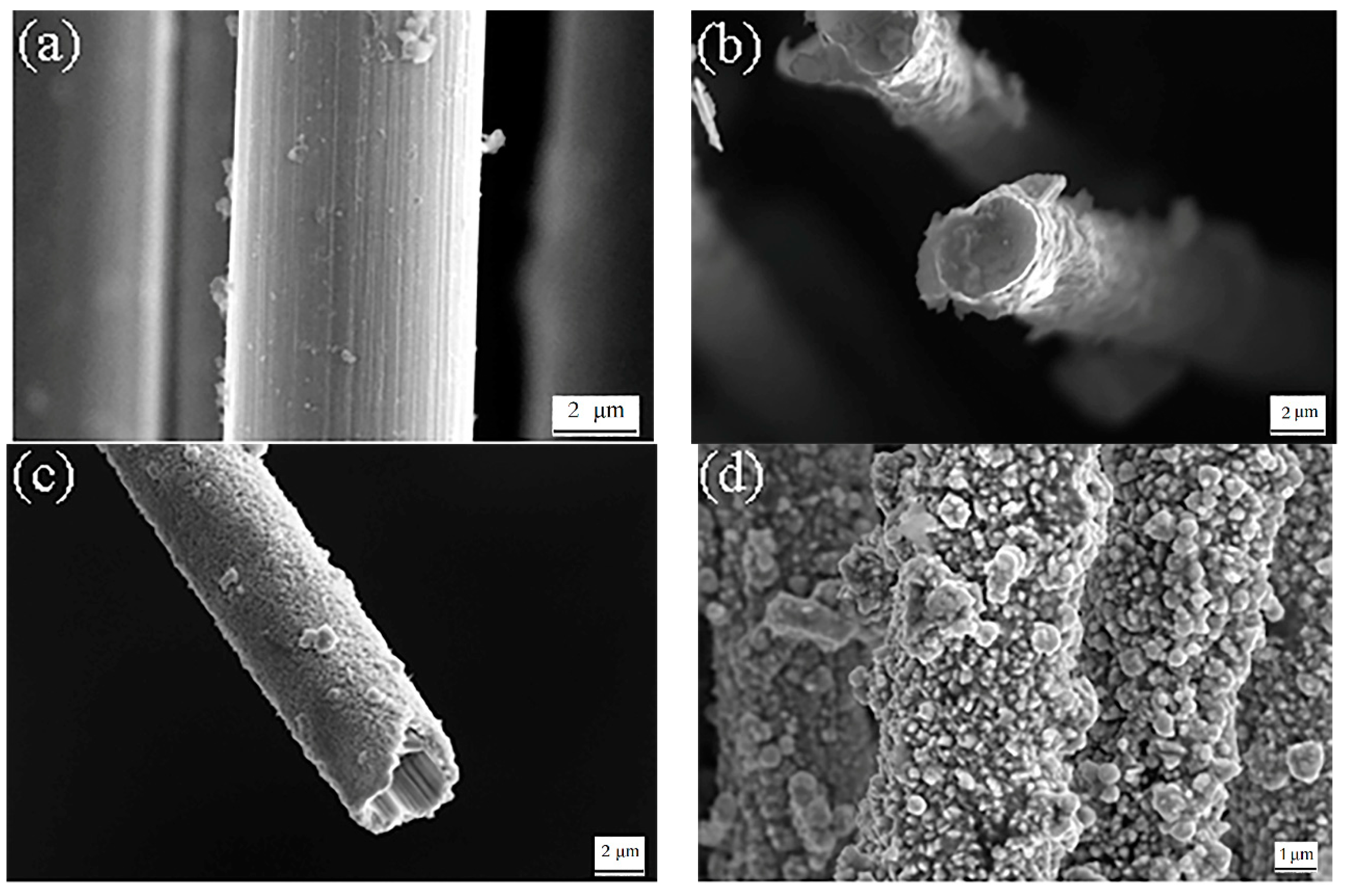
3.1. Morphology Observation

Figure 1 shows the macroscopic morphology of the braided carbon fiber rope before and after copper plating. For this paper, a uniform and strong copper plating layer was obtained on the surface of the braided carbon fiber rope by using suitable electroless copper plating technology.
Figure 2 shows an SEM image before and after carbon fiber copper plating. The raw carbon fiber surface was smooth and flat as shown in Figure 2a. In electroless copper plating, the copper plating layer can be deposited from the groove on the surface of the carbon fiber and sufficiently filled to achieve a firm physical bond between the coating and the carbon fiber. Figure 2b shows the surface of the copper-plated carbon fiber. It can be seen that the copper-plated layer on the surface of the carbon fiber was composed of continuous equiaxed copper particles. The coating was dense and has no obvious peeling phenomenon. Figure 2c shows that, after Cu-plated, the carbon fiber bottom was completely covered with a copper layer, which can effectively improve the combining of the carbon fiber and the aluminum matrix. When the composite material was subjected to an external force, the force could be transmitted to the carbon fiber through the Al matrix, and carbon fiber became the main body of bearing capacity. The cross-sectional morphology of the copper-plated carbon fiber is shown in Figure 2d, which indicates that the surface of the carbon fiber was uniformly coated with a layer of metal Cu along the periphery of the fiber, and the thickness ranged of the coating from 620 nm to 800 nm.

3.2. Structural Analysis

The XRD spectra of the Cu-coated braided carbon fiber rope was shown in Figure 3b. There were three strong diffraction peaks at 2θ at 43.29°, 50.43°, and 74.13° correspond to the (111), (200), and (220) crystal plane of Cu, respectively. The crystal face was found to have a characteristic peak corresponding to the (002) crystal plane of graphite at 2θ = 25°, and the corresponding peak of the coated carbon fiber was weaker than that of the uncoated carbon fiber as shown in Figure 3a. It clearly indicated that Cu was successfully coated on the surface of braided carbon fiber rope by XRD analysis [32]. Figure 4 was an energy spectrum analysis of copper-plated carbon fiber. According to the EDS results, the surface of the carbon fiber after dip-coating mainly contains Cu element, and its mass fraction was 97.11%. Furthermore, there was a small amount of O element with a mass fraction of 2.89%. This indicates that there was no obvious oxidative damage on the surface of the carbon fiber. Cu in the coating mainly exists as a simple substance, and only a very small amount of Cu was oxidized, which will be verified again in the subsequent XPS results.

3.3. Effect of pH Value on Electroless Copper Plating Reaction

In electroless copper plating, pH is a very important parameter, which has a great influence on the copper deposition rate, the quality of the coating, and the stability of the solution. In this experiment, the role of sodium hydroxide was to adjust the pH of the plating solution so that the reduction reaction of formaldehyde is carried out under alkaline conditions. When the pH of the plating solution was 10, the coating quality of the surface topography of the electroless copper plating layer was very poor, and almost no copper was deposited on the surface of the carbon fiber. As shown in Figure 5a, the surface of the carbon fiber after plating did not occur. The color change visible to the naked eye indicates that the bath activity was not high at this pH value, and copper ions were difficult to deposit on the surface of the carbon fiber. When the pH of the plating solution was 11, a small portion of copper was deposited on the surface of the carbon fiber, and a thin copper layer appeared on the surface of the carbon fiber. As shown in Figure 5b, the surface of the carbon fiber after plating was yellow, indicating that, at this pH value, a portion of the copper layer can be formed on the surface of the carbon fiber. When the pH of the plating solution is 12, a continuous and uniform copper plating layer was formed on the surface of the carbon fiber, which was dense and had no obvious peeling phenomenon. As shown in Figure 5c, the surface of the carbon fiber after plating was bright copper red. When the pH of the plating solution was 13, the undulating, low-densitied, uneven plating surface was obtained. As shown in Figure 5d, the surface of the carbon fiber after plating was dark red.
Under the conditions of this paper, when the pH is 12, the surface of the coating is smoothest. When the pH is greater than 12, a new reaction is formed on the original crystal grains since the reaction is severe, and the crystal grains are too late to grow into regular crystal grains. The crystal nucleus, as the surface coating of the fiber is not smooth, showing the accumulation of rhombohedral structure, the surface particle size is uneven, and disorganized.
According to the above experimental results and analysis, when the pH value of electroless copper plating on the surface of carbon fiber is 12, the effect is the best. In addition, in order to maintain the constant quality and thickness of the coating on the surface of the carbon fiber, the pH of the plating solution should be kept as constant as possible during the coating process. Different levels pH in surface modification are important reasons for the difference in coating structure. In addition, the stability of the plating solution and the effect of removing glue on the surface of the carbon fiber are also important factors.

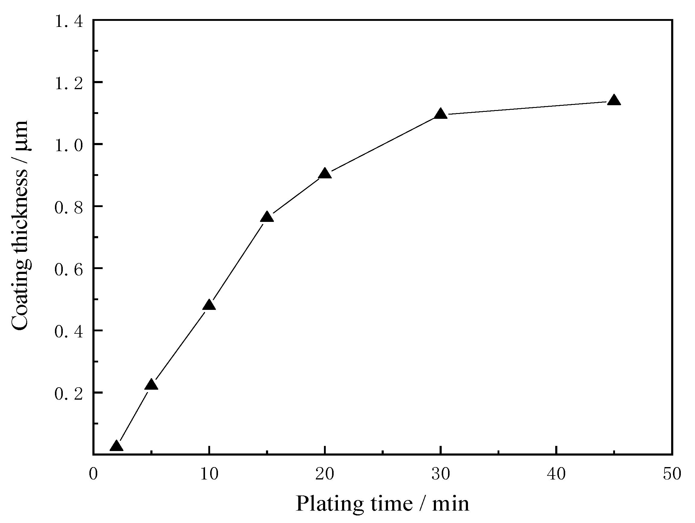
3.4. Effect of Plating Time on Coating

The plating time is a major factor in controlling the thickness and quality of the coating. Figure 6 shows the relationship between plating time and plating thickness. It can be seen from the figure that the thickness of the plating layer increases with the increase of the plating time but the increase amplitude gradually decreases. Since the thickness of the coating required for this experiment is 0.5 to 1 μm, the time is controlled at about 15 min. The change in coating thickness is related to the surface-coated catalyst particles. At the beginning of copper plating, the catalyst Pd can provide sufficient nucleation sites, so that Cu2+ in the plating solution can quickly deposit nucleation on the catalyst Pd after reduction by the catalyst, the reaction deposition rate is higher, and the thickness of the coating increases faster. With the continuous deposition of Cu2+ in the nucleation site in the plating solution, after the carbon fiber surface is completely covered with copper particles, the reduced Cu can only be deposited on the original copper particles, and its catalytic reduction activity decreases. The concentration of Cu2+ was greatly reduced, resulting in a slow increase in the thickness of the coating after 30 min.
In this experiment, when the thickness of the coating is 0.5 to 1 μm, the carbon fiber and the coating are tightly bonded. As the thickness of the coating increases, the density of the coating decreases, the peeling between the coating and the carbon fiber occurs, and the interface bonding state becomes poor. The two main reasons are as follows: Firstly, the formation of the coating is a dynamic growth process in which the reduced copper atoms in the plating solution continue to nucleate and grow on the surface of the carbon fiber. Within a certain range, the thicker the coating, the larger the microcrystalline size inside the coating, and the internal stress of the crystal due to anisotropy increases at the interface, which weakens the interface between the coating and the carbon fiber. Secondly, there are a large number of grooves on the surface of the carbon fiber after oxidation treatment, which increases the specific surface area of the carbon fiber. With the increase of the plating time, the grain size on the surface of the fiber increases, and large grains have difficulty entering the inside of the carbon fiber grooves, making the interface bonding poor.

3.5. Mechanism of Electroless Copper Plating on Carbon Fiber Surface

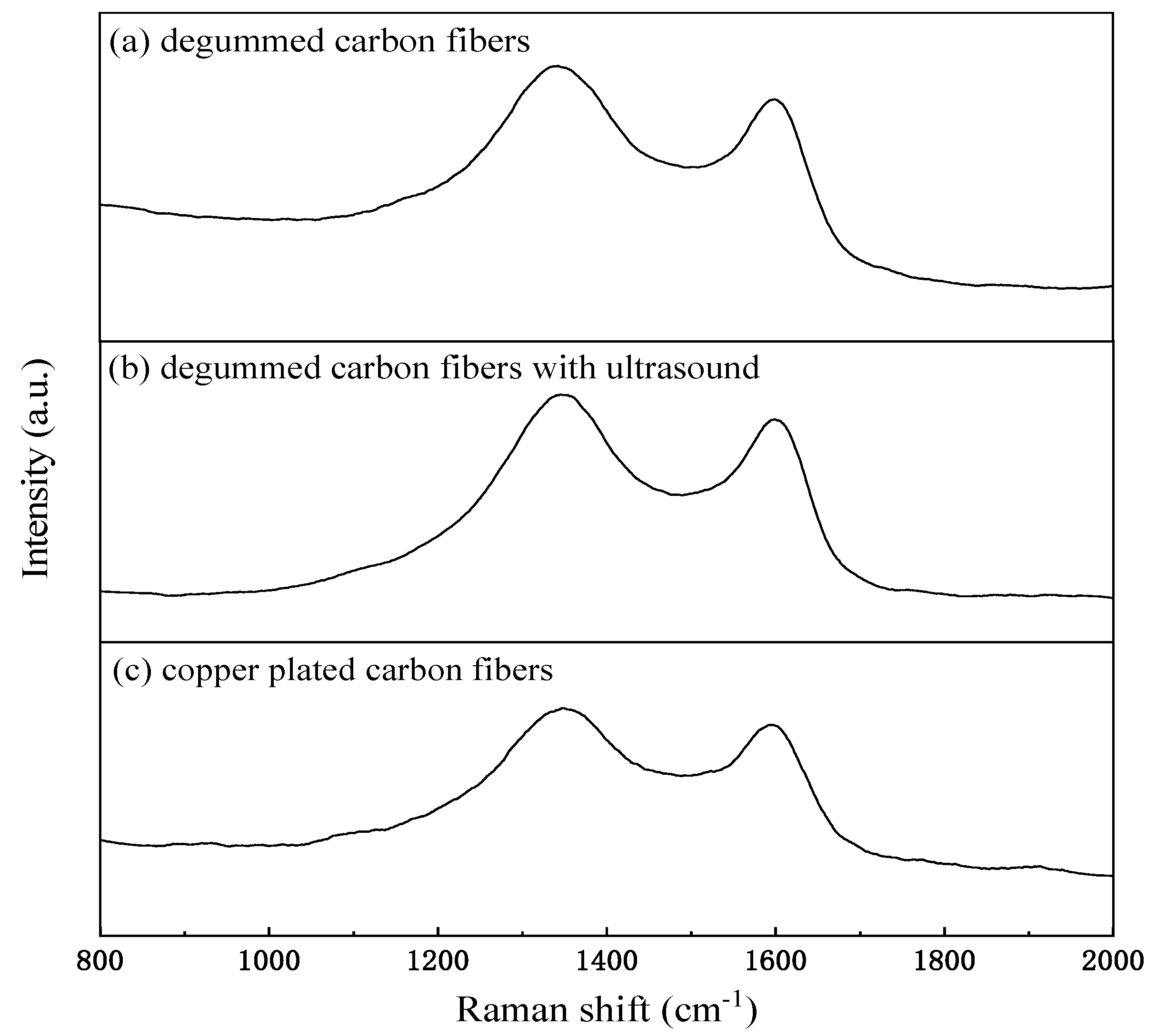
3.5.1. Raman Analysis

Raman analysis has been known to be a useful method to characterize the surface structure of carbon fibers. Raman spectrum of carbon fibers usually show two main peaks, which identified as the D band (about 1358 cm−1) and G band (about 1582 cm−1) [34]. In general, the D band is connected with asymmetric carbon atoms and structural defects, which can be seen in the single crystal graphite [35]. The G band is taken for strong vibrations in the opposite direction of connected carbon atoms in the plane of the graphite mesh [36]. Raman spectrum of degummed carbon fibers, degummed carbon fibers with ultrasound, and Cu plated carbon fibers in the 800–2000 cm−1 region with an excitation wavelength of 532 nm are shown in Figure 7. With the process of Ultrasonic treatment, the structural disorder of carbon fibers was reduced. It is considered to be attributed to the oxidation of ultrasound [37]. After Ultrasonic treatment, the Raman spectrum of the carbon fibers showed a higher relative intensity ratio ID/IG, indicating an increase in both degree of disorder and the amount of the functional groups. The intensity of the D peak also decreases with the oxidation time, while the position remains unchanged, and the FWHF of the D and G bands gradually narrows, indicating that the chemical heterogeneity is reduced and the structural order is increased.

3.5.2. XPS Analysis

In order to further analyze the types and contents of functional groups on the surface of the braided carbon fiber rope, the samples of the degummed and copper plated braided carbon fiber rope were both tested by XPS analysis.
XPS spectra analysis of the braided carbon fiber rope after degumming treatment is shown in Figure 8a. It was found that the carbon fiber surface contained C and O elements at the binding energy of 284.82 eV and 532.93 eV, respectively. The oxygen content is about 14.81%, which is mainly due to oxidation during the degumming process. The pretreatment process not only increases the specific surface area of the carbon fiber surface but also increases its surface activity. The C1s peak was subjected to peak fitting processing (Figure 8b). It was found that the surface of the braided carbon fiber rope after degumming had many oxygen-containing functional groups. The relative content of various functional groups was measured by Advantage treatment by reference to the XPS manual, as shown in Table 3, the C-OH content is about 24.83%, the C=O content is about 1.71%, the COOH content is about 2.59%, and the oxygen-containing functional groups on the surface are obviously increased, which also makes the braided carbon fiber rope more hydrophilic and provides a good basis for subsequent copper plating tests.
In order to determine the chemical composition in the coating, XPS spectrum analysis was performed on the surface of the copper-plated braided carbon fiber rope, and a peak-fitting analysis was performed on the Cu2p peak. As shown in Figure 9a, a survey spectrum analysis of copper-plated carbon fibers found that there were other small impurity elements in addition to the Cu, C and O elements in the coating. These impurity elements were derived from the plating solution, such as a peak near 1071 eV, which was determined to be a Na element. This is due to the fact that NaOH remains on the surface of the carbon fiber when the pH is adjusted during the configuration of the plating solution. It can be seen from the spectrum that there were obvious carry-up peaks near the main peak of Cu2p (after photoionization, the transition of valence electrons from occupied orbits to higher unoccupied orbits due to the excitation of the inner electrons; this transition process is called carry-on process, and the energy loss peak that appears at the high binding energy end of the XPS main peak is the carry-on peak), indicating that these elements have undergone energy level splitting during the binding process, in other words, the valence state of these elements has changed [38]. The peak fitting analysis of the Cu2p peak is shown in Figure 9b. The main peak does not show a strong satellite structure. The fitted peak appears at 934 eV, which corresponds to CuO. This is mainly due to the contact between the copper-plated carbon fiber and the air, resulting in oxidation of the surface of the copper-plated layer.

3.6. Interface and Mechanical Properties of Carbon Fiber and Aluminum Matrix Composites

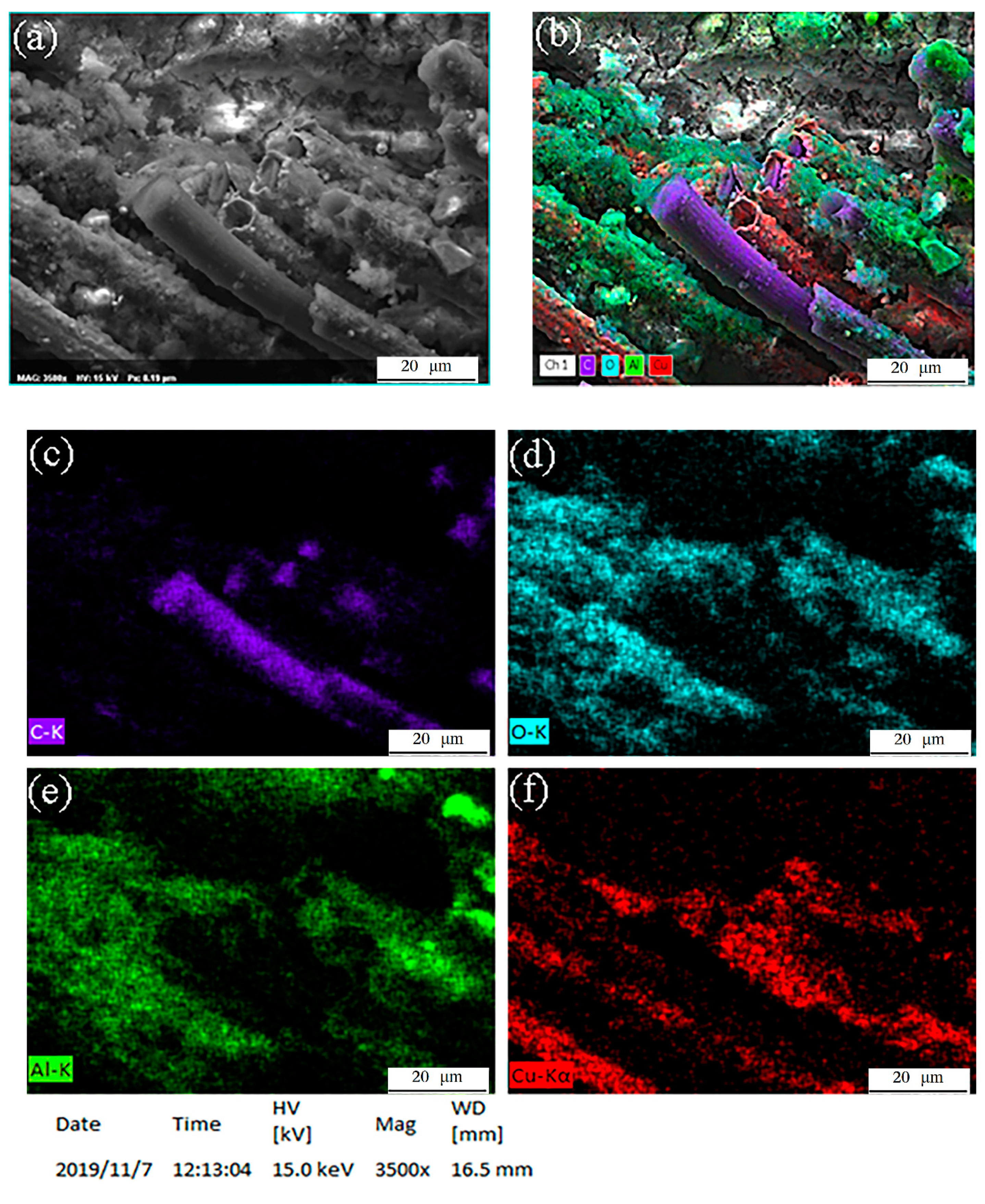
3.6.1. Element Distributions

The micro-morphology of copper-plated carbon fiber and aluminum-based composite materials is shown in Figure 10a. The EDS element surface scanning analysis of the C, Al, Cu, and O elements in this field of view was performed, and the result integration is shown in Figure 10b.The copper plating on the surface of a few carbon fibers is peeled off, and, due to the loss of the fixation and protection of the coating, the integrity of the carbon fiber and the original distribution of the carbon fiber are damaged, resulting in an increase of defects, such as breakage, damage, and misalignment of the fibers in the composite material. C-elements came from carbon fibers and were mainly distributed in the shape of lines where the carbon fibers appear. Cu elements were distributed around the bonding interface between the carbon fibers and the matrix in dots or lines. Al the elements were the absolute majority distributed in areas other than carbon fibers.

3.6.2. Strengthening Effect of Braided Carbon Fiber Rope on Aluminum Matrix Composite

Braided carbon fiber rope is a braid formed by continuous interweaving fiber bundles, which belongs to a non-layered whole. Since the braided fibers are connected into an organic whole, the composite material shows strong integrity, and at the same time, the phenomenon of interlayer separation between the carbon fiber bundle and the aluminum matrix is overcome. Moreover, the braided carbon fiber rope has geometric complexity compared to a single carbon fiber bundle and can weave various two-dimensional and three-dimensional braided structures to meet the complex geometric requirements of composite products, including various cross-section profiles, different forms of plates, Pipes with complex geometries, etc. Braided carbon fiber ropes have more obvious advantages in terms of designability than carbon fiber bundles. It can adjust the geometric parameters, such as the weaving angle, weaving unit, number of fiber bundles, and fiber volume of braided carbon fiber rope according to the performance and use of the product, so as to achieve the optimal design of knitted composite products.
Figure 11 shows a comparison of the tensile properties of a single aluminum matrix and two other materials with carbon fiber bundles and braided carbon fiber ropes as reinforcements. As shown in Figure 11, the tensile strength of the composite material with the carbon fiber bundle as the reinforcing phase is 69 MPa, which is 14% higher than the pure aluminum matrix, The tensile strength of the composite material with the braid carbon fiber rope as the reinforcing phase is 83 MPa, which is 31% higher than that of pure aluminum matrix, indicating that the reinforcing effect of braided carbon fiber rope is better than carbon fiber bundle.
Figure 12 shows the comparisons of the tensile properties: Cu-coated and uncoated braided carbon fibers, as well as Cu-coated and uncoated carbon fiber bundle. The number of samples is 5, and the measurement results are averaged.
The theoretical tensile strength of the unidirectional carbon fiber bundle reinforced aluminum matrix composites, according to the mixing criteria (ROM) calculated for the strength of the composite, is shown in Equation (1):
σ c = σ f V f + σ m ( 1 V f )
where σc, σf, and σm are the tensile strengths of the composite material, the carbon fiber, and the matrix material, respectively. Vf is the volume fraction of reinforced carbon fibers in the composite.
The carbon fiber braided rope is in a sinusoidal buckling state in the aluminum matrix. The theoretical method for calculating the theoretical tensile strength cannot be simply calculated by using the mixed method of unidirectional carbon fiber bundle reinforced composite material strength. Instead, the following Equation (2) should be used to calculate its theoretical tensile strength:
σ c = σ f V f cos θ + σ m ( 1 V f )
where σc, σf, and σm are the tensile strengths of the composite material, the carbon fiber, and the matrix material, respectively. θ is the average orientation angle of the braid carbon fiber rope relative to the axial stretching direction (as shown in Figure 13), and Vf is the volume fraction of reinforced carbon fibers in the composite.
According to Equations (1) and (2), when the volume fraction of the reinforcing phase carbon fiber in the composite material is 4%, the theoretical tensile strength of the composite material with the carbon fiber bundle and the braided carbon fiber rope as the reinforcing phase was 254 MPa and 227 MPa, and the measured tensile strength reached 27% and 36% of its theoretical tensile strength, respectively.
Due to the high strength characteristics of carbon fibers, they play a major bearing role in composite materials, and carbon fibers dominate the axial tensile strength of composite materials. However, in addition to the influence of carbon fibers, the mechanical properties of composite materials are also affected by impregnation defects. Because of the poor wettability of carbon fiber and aluminum matrix, susceptible by the capillary force and viscous resistance during infiltration, it is easy to form infiltration defects in the composite material, which ultimately causes its decline of performance. In addition, during the preparation of the composite material, the high temperature aluminum liquid causes the surface damage and local carbonization of the carbon fiber and also causes the strength of the carbon fiber to decrease.
Carbon fiber also has the characteristics of high modulus, according to the mixing criteria (ROM) calculated for the modulus of the composite, as shown in Equation (3):
E c = E f V f + E m ( 1 V f )
where Ec, Ef, and Em are the modulus of the composite material, the carbon fiber, and the matrix material. According to Equation (3), when the volume fraction of the reinforcing phase carbon fiber in the composite material is 4%, the theoretical modulus of the composite material is 77 GPa, and the measured modulus is 78 GPa, so the two values are very close. It shows that the rule of mixer is more valid for modulus than strength.

4. Conclusions

(1)
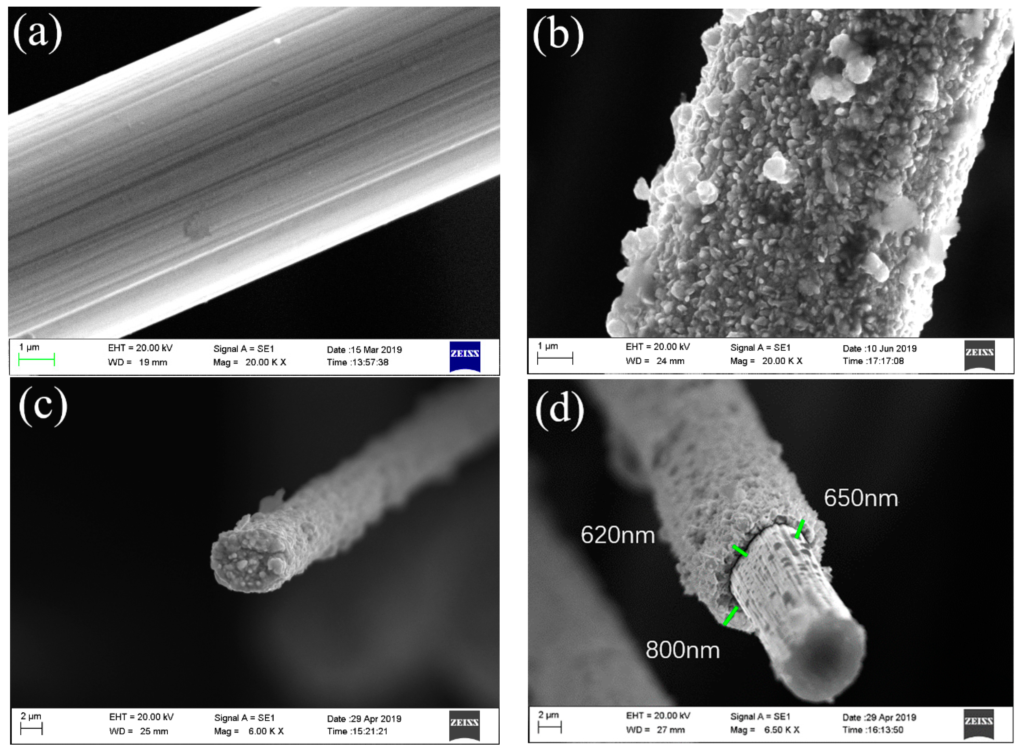
The surface of the braided carbon fiber rope treated with ultrasonic degumming and concentrated nitric acid becomes rough, and the axial groove-like streaks were obviously increased. By XPS analysis, the carbon fiber surface contained many hydrophilic oxygen-containing functional groups, such as C–OH, C=O, COOH, etc., which can effectively improve the wettability of carbon fiber and plating solution, as well as ensure the smooth progress of copper plating.
(2)
The tensile strength of the composite material was higher than that of the matrix material, and the reinforcing effect of the carbon fiber rope was better than that of the carbon fiber bundle. When the volume fraction of the reinforcing phase carbon fiber was 4%, the tensile strength of the carbon fiber bundle reinforced composite material was 14% higher than that of the matrix, and the tensile strength of the carbon fiber rope reinforced composite was 31% higher than that of the matrix.
(3)
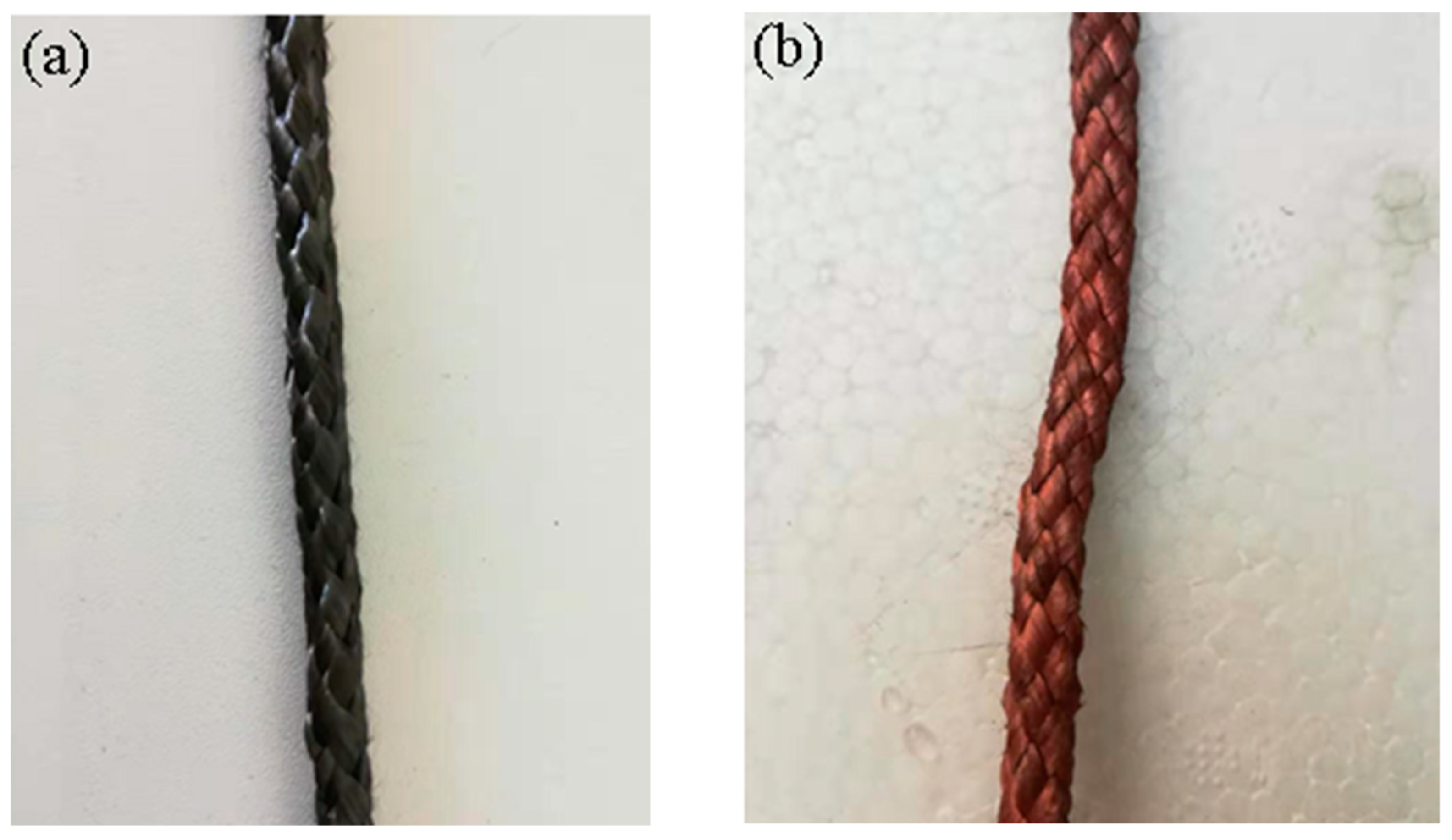
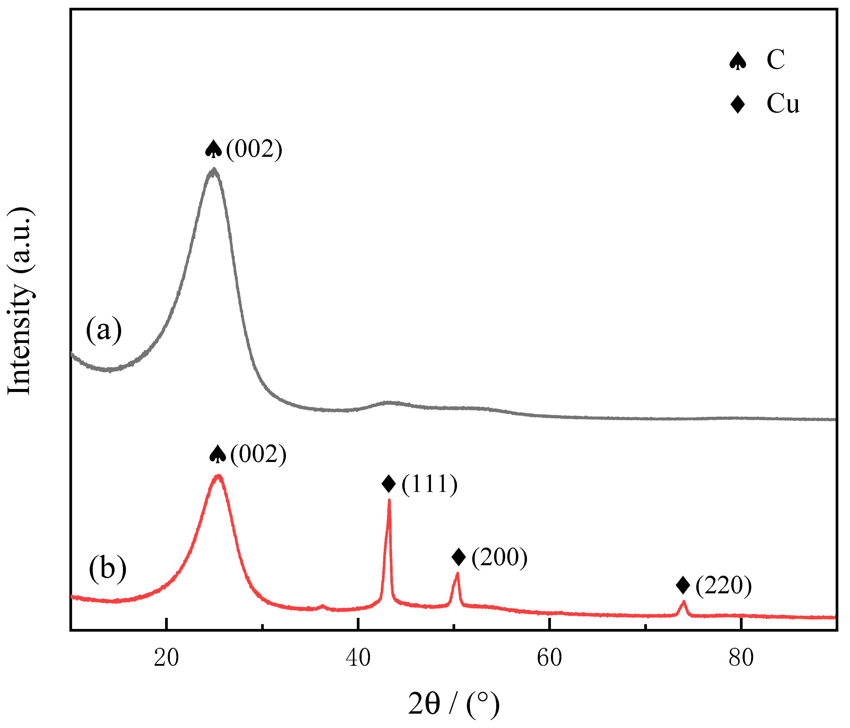
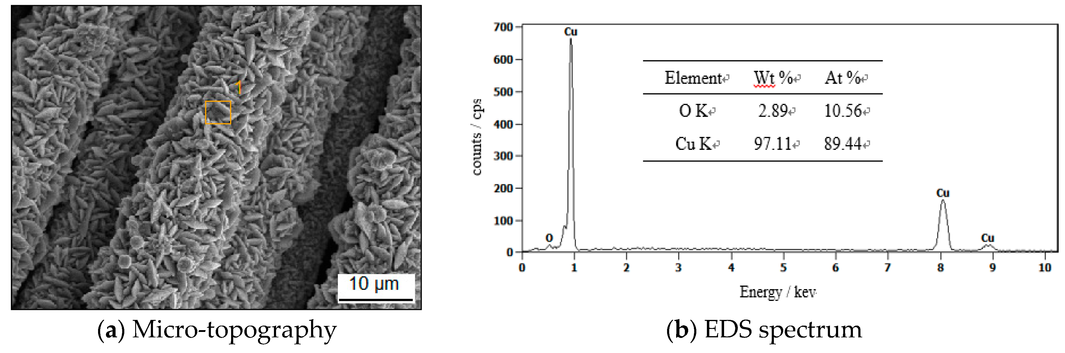
The comparative analysis of the copper coating on the carbon fiber surface obtained from different pH of the plating solution shows that, when pH = 12, a continuous and uniform copper plating layer was formed on the carbon fiber surface, and the coating was dense without obvious peeling.
(4)
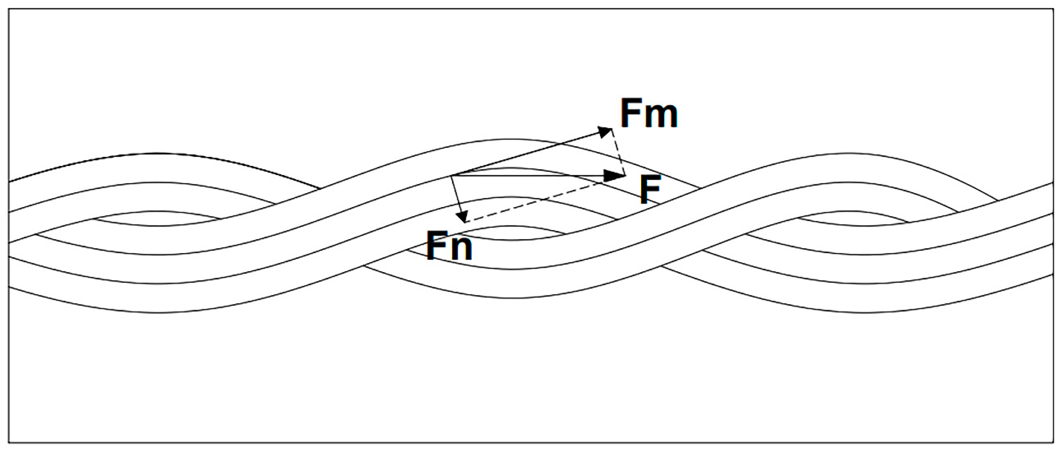
The main way to strengthen the carbon fiber braided rope is that the surface of the carbon fiber braided rope is wavy and uneven, which increases the contact area with the aluminum matrix and reaches a state of physical engagement with the aluminum matrix, thereby forming a whole.

Author Contributions

J.L. writing—original draft, methodology; C.W. writing-review & editing; H.P. Data curation; M.W. Formal analysis; W.T. writing-review & editing. All authors have read and agreed to the published version of the manuscript.

Funding

This work is supported by the National Natural Science Foundation of China with Grant (No. 51274038).

Conflicts of Interest

The authors declare no conflict of interest.

References

  1. Shirvanimoghaddam, K.; Hamim, S.U.; Karbalaei Akbari, M.; Fakhrhoseini, S.M.; Khayyam, H.; Pakseresht, A.H.; Ghasali, E.; Zabet, M.; Munir, K.S.; Jia, S.; et al. Carbon fiber reinforced metal matrix composites: Fabrication processes and properties. Compos. Part A Appl. Sci. Manuf. 2017, 92, 70–96. [Google Scholar] [CrossRef]
  2. Xavior, M.A.; Kumar, J.P.A. Machinability of Hybrid Metal Matrix Composite—A Review. Procedia Eng. 2017, 174, 1110–1118. [Google Scholar] [CrossRef]
  3. Zhang, J.J.; Liu, S.C.; Chen, H.; Lu, Y.P.; Chen, Q.S.; Dong, Y.; Wang, T.M.; Li, T.J. Surface Pretreatment and Fabrication Technology of Woven Carbon Fiber Cloth Aluminium Alloy Matrix Composite. Mater. Sci. Forum 2015, 816, 3–8. [Google Scholar] [CrossRef]
  4. Barton, B.E.; Behr, M.J.; Patton, J.T.; Hukkanen, E.J.; Landes, B.G.; Wang, W.; Horstman, N.; Rix, J.E.; Keane, D.; Weigand, S.; et al. High-Modulus Low-Cost Carbon Fibers from Polyethylene Enabled by Boron Catalyzed Graphitization. Small 2017, 13, 1701926. [Google Scholar] [CrossRef] [PubMed]
  5. Newcomb, B.A. Processing, structure, and properties of carbon fibers. Compos. Part A Appl. Sci. Manuf. 2016, 91, 262–282. [Google Scholar] [CrossRef]
  6. Xiao, H.; Lu, Y.; Zhao, W.; Qin, X. The effect of heat treatment temperature and time on the microstructure and mechanical properties of PAN-based carbon fibers. J. Mater. Sci. 2014, 49, 794–804. [Google Scholar] [CrossRef]
  7. Hajjari, E.; Divandari, M.; Arabi, H. Effect of Applied Pressure and Nickel Coating on Microstructural Development in Continuous Carbon Fiber-Reinforced Aluminum Composites Fabricated by Squeeze Casting. Mater. Manuf. Process. 2011, 26, 599–603. [Google Scholar] [CrossRef]
  8. Tang, Y.; Liu, L.; Li, W.; Shen, B.; Hu, W. Interface characteristics and mechanical properties of short carbon fibers/Al composites with different coatings. Appl. Surf. Sci. 2009, 255, 4393–4400. [Google Scholar] [CrossRef]
  9. Liu, L.; Li, W.; Tang, Y.; Shen, B.; Hu, W. Friction and wear properties of short carbon fiber reinforced aluminum matrix composites. Wear 2009, 266, 733–738. [Google Scholar] [CrossRef]
  10. Liu, L.; Tang, Y.; Zhao, H.; Zhu, J.; Hu, W. Fabrication and properties of short carbon fibers reinforced copper matrix composites. J. Mater. Sci. 2008, 43, 974–979. [Google Scholar] [CrossRef]
  11. Panwar, N.; Chauhan, A. Fabrication methods of particulate reinforced Aluminium metal matrix composite-A review. Mater. Today Proc. 2018, 5, 5933–5939. [Google Scholar] [CrossRef]
  12. Akbarzadeh, E.; Picas, J.A.; Teresa Baile, M. Microstructure and properties of aluminum silicon/short fibre carbon composites fabricated by semi-solid thixomixing. Mater. Des. 2015, 88, 683–692. [Google Scholar] [CrossRef] [Green Version]
  13. Xue, J.; Wang, W.; Hu, J.; Zhang, J.; Wu, S. Influence of fiber length on the tensile behavior of fiber metal laminates with discontinuous reinforcement. J. Reinf. Plast. Compos. 2015, 34, 1651–1661. [Google Scholar] [CrossRef]
  14. Liu, T.; He, X.; Liu, Q.; Ren, S.; Kang, Q.; Zhang, L.; Qu, X. Effect of chromium carbide coating on thermal properties of short graphite fiber/Al composites. J. Mater. Sci. 2014, 49, 6705–6715. [Google Scholar] [CrossRef]
  15. Shi, J.; Liu, Y.; Yao, G.; Yan, P.; Liu, H. Effect of Mg on Microstructure and Mechanical Properties of Copper-Coated Short Carbon Fiber Reinforced Al Alloy Matrix Composite. In Advanced Materials Research; Gao, S., Ed.; Trans Tech Publications Ltd.: Cambridge, UK, 2012; Volume 457, pp. 348–353. [Google Scholar]
  16. Zhang, Y.; Yan, L.; Miao, M.; Wang, Q.; Wu, G. Microstructure and mechanical properties of z-pinned carbon fiber reinforced aluminum alloy composites. Mater. Des. 2015, 86, 872–877. [Google Scholar] [CrossRef]
  17. Beronska, N.; Izdinsky, K.; Stefanik, P.; Kudela, S., Jr.; Simancik, F.; Vavra, I.; Krizanova, Z. Structure and thermal expansion behaviour of Al/C composites reinforced with unidirectionally aligned continuous high modulus C fibres. Met. Mater. 2011, 49, 435–446. [Google Scholar] [CrossRef]
  18. Rohatgi, P.K.; Tiwari, V.; Gupta, N. Squeeze infiltration processing of nickel coated carbon fiber reinforced Al-2014 composite. J. Mater. Sci. 2006, 41, 7232–7239. [Google Scholar] [CrossRef]
  19. Ramesh, C.S.; Adarsha, H.; Pramod, S.; Khan, Z. Tribological characteristics of innovative Al6061–carbon fiber rod metal matrix composites. Mater. Des. 2013, 50, 597–605. [Google Scholar] [CrossRef]
  20. Calderon, N.R.; Voytovych, R.; Narciso, J.; Eustathopoulos, N. Wetting dynamics versus interfacial reactivity of AlSi alloys on carbon. J. Mater. Sci. 2010, 45, 2150–2156. [Google Scholar] [CrossRef]
  21. Xue, Y.; Chen, W.; Zhao, Q.; Fu, Y. Electroless carbon fibers: A new route for improving mechanical property and wettability of composites. Surf. Coat. Technol. 2019, 358, 409–415. [Google Scholar] [CrossRef]
  22. Che, D.; Yao, G.; Cao, Z. A Precious Metal-Free Electroless Technique for the Deposition of Copper on Carbon Fibers. Metall. Mater. Trans. A 2012, 43, 4194–4199. [Google Scholar] [CrossRef]
  23. Kang, S.S.; Ji, H.; Gul, H.Z.; Sakong, W.K.; Kim, J.Y.; Kim, W.S.; Lee, J.; Han, S.; Park, M.; Choi, Y.C.; et al. Metal-coated carbon fiber for lighter electrical metal wires. Synth. Met. 2016, 222, 180–185. [Google Scholar] [CrossRef]
  24. Halouzka, V.; Halouzkova, B.; Jirovsky, D.; Hemzal, D.; Ondra, P.; Siranidi, E.; Kontos, A.G.; Falaras, P.; Hrbac, J. Copper nanowire coated carbon fibers as efficient substrates for detecting designer drugs using SERS. Talanta 2017, 165, 384–390. [Google Scholar] [CrossRef] [PubMed]
  25. Asano, K. Mechanical Properties of Aluminum Composites Reinforced with PAN- and Pitch-Based Short Carbon Fibers. Mater. Trans. 2017, 58, 906–913. [Google Scholar] [CrossRef] [Green Version]
  26. Knowles, A.J.; Jiang, X.; Galano, M.; Audebert, F. Microstructure and mechanical properties of 6061 Al alloy based composites with SiC nanoparticles. J. Alloys Compd. 2014, 615, S401–S405. [Google Scholar] [CrossRef]
  27. Matsunaga, T.; Matsuda, K.; Hatayama, T.; Shinozaki, K.; Yoshida, M. Fabrication of continuous carbon fiber-reinforced aluminum–magnesium alloy composite wires using ultrasonic infiltration method. Compos. Part A Appl. Sci. Manuf. 2007, 38, 1902–1911. [Google Scholar] [CrossRef]
  28. Zhang, J.; Liu, S.; Zhang, Y.; Dong, Y.; Lu, Y.; Li, T. Fabrication of woven carbon fibers reinforced Al–Mg (95–5 wt%) matrix composites by an electromagnetic casting process. J. Mater. Process. Technol. 2015, 226, 78–84. [Google Scholar] [CrossRef]
  29. Parandoush, P.; Zhou, C.; Lin, D. 3D Printing of Ultrahigh Strength Continuous Carbon Fiber Composites. Adv. Eng. Mater. 2019, 21, 1800622. [Google Scholar] [CrossRef]
  30. Wang, L.; Nygren, G.; Karkkainen, R.L.; Yang, Q. A multiscale approach for virtual testing of highly aligned short carbon fiber composites. Compos. Struct. 2019, 230, 111462. [Google Scholar] [CrossRef]
  31. Liu, B.; Hu, X.; Li, Y.; Xiao, T.; Xu, F. Internal three-dimensional strain evolution of the failure process for short carbon fiber composite through in situ synchrotron radiation X-ray computed tomography. Carbon 2020, 157, 506–514. [Google Scholar] [CrossRef]
  32. Aytaç, A.; Gürbüz, M.; Sanli, A.E. Electrooxidation of hydrogen peroxide and sodium borohydride on Ni deposited carbon fiber electrode for alkaline fuel cells. Int. J. Hydrogen Energy 2011, 36, 10013–10021. [Google Scholar] [CrossRef]
  33. Abdel Gawad, O.; Abou Tabl, M.H.; Abdel Hamid, Z.; Mostafa, S.F. Electroplating of chromium and Cr-carbide coating for carbon fiber. Surf. Coat. Technol. 2006, 201, 1357–1362. [Google Scholar] [CrossRef]
  34. Skrabalak, S.E. Ultrasound-assisted synthesis of carbon materials. Phys. Chem. Chem. Phys. 2009, 11, 4930. [Google Scholar] [CrossRef] [PubMed]
  35. Tzeng, S. Catalytic graphitization of electroless Ni–P coated PAN-based carbon fibers. Carbon 2006, 44, 1986–1993. [Google Scholar] [CrossRef]
  36. Ferrari, A.C.; Robertson, J. Interpretation of Raman spectra of disordered and amorphous carbon. Phys. Rev. B 2000, 61, 14095–14107. [Google Scholar] [CrossRef] [Green Version]
  37. Liu, S.; Qiao, X.; Liu, W.; Shi, S.; Qu, Y. Mechanism of ultrasonic treatment under nickel salt solution and its effect on electroless nickel plating of carbon fibers. Ultrason. Sonochem. 2019, 52, 493–504. [Google Scholar] [CrossRef]
  38. Biesinger, M.C. Advanced analysis of copper X-ray photoelectron spectra. Surf. Interface Anal. 2017, 49, 1325–1334. [Google Scholar] [CrossRef]
Figure 1. The macro morphology of braided carbon fiber rope: (a) uncoated braided carbon fiber rope; (b) Cu-coated braided carbon fiber rope.
Metals 10 01212 g001
Figure 2. The micro morphology of Cu-coated braided carbon fiber rope: (a) as-received carbon fiber; (b) surface coating of carbon fiber; (c) ends of copper plated carbon fiber; (d) cross section of copper plated carbon fiber.
Metals 10 01212 g002
Figure 3. XRD spectra: (a) uncoated braided carbon fiber rope; (b) Cu-coated braided carbon fiber rope.
Metals 10 01212 g003
Figure 4. EDS spectrum of copper-plated carbon fibers: (a) Micro-topography, (b) EDS spectrum.
Metals 10 01212 g004
Figure 5. The surface morphology of copper deposits on carbon fibers at different pH value in the solution: (a) pH 10; (b) pH 11; (c) pH 12; (d) pH 13.
Metals 10 01212 g005
Figure 6. Variation of coating thickness with plating time.
Metals 10 01212 g006
Figure 7. Raman spectroscopy of carbon fibers: (a) degummed carbon fibers; (b) degummed carbon fibers with ultrasound; (c) copper plated carbon fibers.
Metals 10 01212 g007
Figure 8. XPS spectra of the degummed braided carbon fiber rope: (a) survey XPS spectra; (b) C1s spectra.
Metals 10 01212 g008
Figure 9. XPS spectra of the Cu coated braided carbon fiber rope: (a) survey XPS spectra; (b) Cu2p spectra.
Metals 10 01212 g009
Figure 10. Micro-morphology and elements map-scanning result of copper-plated carbon fiber and aluminum matrix composites: (a) morphology; (b) element mapping-scanning analysis; (c) C distribution; (d) O distribution; (e) Al distribution; (f) Cu distribution.
Metals 10 01212 g010
Figure 11. Results of mechanical properties test of composite materials.
Metals 10 01212 g011
Figure 12. Tensile strength of different materials: (a) braided carbon fiber rope; (b) carbon fiber bundle.
Metals 10 01212 g012
Figure 13. Stress of braided carbon fiber rope in aluminum matrix.
Metals 10 01212 g013
Table 1. Main performance parameters of carbon fibers.
Fiber Diameter/μmCarbon Content/%Linear Density/mg·m−1Bulk Density/g·cm−3Tensile Strength/GPaElastic Modulus/GPaElongation at Break/%
793.0–95.08001.804.902302.10
Table 2. Key components and their concentrations for electroless copper plating solution.
ComponentMolecular FormulaConcentrationFunction
Copper sulfateCuSO4·5H2O10g·L−1Main salt
Seignette saltKNaC4H4O6·4H2O10g·L−1Complexing agent
FormaldehydeHCHO10mL·L−1Reducing agent
Sodium hydroxideNaOHvariableAdjusting pH
Table 3. Functional group content on the surface of pretreated braided carbon fiber rope.
C=CC–OHC=OCOOH
EbAt.%EcAt.%EdAt.%EeAt.%
284.7570.86286.3024.83287.481.71288.902.59

