Microstructure and Fracture Toughness of Fe–Nb Dissimilar Welded Joints

 ,
,
Abstract
:1. Introduction
2. Materials and Methods
3. Results and Discussion
4. Conclusions
Author Contributions
Funding
Institutional Review Board Statement
Informed Consent Statement
Data Availability Statement
Conflicts of Interest
References
- Liu, J.Z.; Zhang, L.J.; Yang, H.X.; Xie, M.X.; Shang, X.T.; Zhang, J.X. Enhancement of corrosion protection performance of SUS304/Q235B dissimilar metals lap joint through fiber laser. Int. J. Adv. Manuf. Technol. 2018, 96, 789–802. [Google Scholar]
- Zhang, G.F.; Su, W.; Zhang, J.X.; Wei, Z.X. Friction stir brazing: A novel process for fabricating Al/steel layered composite and for dissimilar joining of Al to steel. Metall. Mater. Trans. A 2011, 42A, 2850–2861. [Google Scholar]
- Zheng, J.S.; Hou, X.M.; Wang, X.B.; Meng, Y.; Zheng, X.; Zheng, L. Isothermal oxidation mechanism of a newly developed Nb-Ti-V-Cr-Al-W-Mo-Hf alloy at 800–1200 °C. Int. J. Refract. Met. Hard Mater. 2016, 54, 322–329. [Google Scholar]
- O’Brien, B.; Stinson, J.; Carroll, W. Development of a new niobium-based alloy for vascular stent applications. J. Mech. Behav. Biomed. Mater. 2008, 1, 303–312. [Google Scholar]
- Mastanaiah, P.; Madhusudhan Reddy, G.; Satya Prasad, K.; Murthy, C.V.S. An investigation on microstructures and mechanical properties of explosive cladded C103 niobium alloy over C263 nimonic alloy. J. Mater. Process. Technol. 2014, 214, 2316–2324. [Google Scholar]
- Budkin, Y.V.; Erofeev, V.A. A physico-mathematical model of the formation of intermetallic compounds in weldbrazing of refractory metals to steel. Weld Int. 2011, 25, 633–637. [Google Scholar]
- Zhao, D.S.; Yan, J.C.; Liu, Y.J.; Ji, Z.S. Interfacial structure and mechanical properties of hot-roll bonded joints between titanium alloy and stainless steel using niobium interlayer. Trans. Nonferrous Met. Soc. China 2014, 24, 2839–2844. [Google Scholar]
- Kumar, A.; Ganesh, P.; Kaul, R.; Bhatnagar, V.K.; Yedle, K.; Sankar, P.R.; Sindal, B.K.; Kumar, K.; Singh, M.K.; Rai, S.K.; et al. A new vacuum brazing route for niobium-316L stainless steel transition joints for superconducting RF cavities. J. Mater. Eng. Perform. 2015, 24, 952–963. [Google Scholar]
- Baghjari, S.H.; Ghaini, F.M.; Shahverdi, H.R.; Mapelli, C.; Barella, S.; Ripamonti, D. Laser welding of niobium to 410 steel with a nickel interlayer produced by electro spark deposition. Mater. Des. 2016, 107, 108–116. [Google Scholar]
- Hajitabar, A.; Naffakh-Moosavy, H. The effect of FexNby (x = 2,7 and y = 1,6) intermetallics on microstructure and mechanical properties of electron beam welded Nb-1Zr refractory alloy. Int. J. Refract. Met. Hard Mater. 2018, 76, 192–203. [Google Scholar]
- Okamoto, H. Fe-Nb (iron-niobium). J. Phase Equilib. 2002, 23, 112. [Google Scholar]
- Voß, S.; Palm, M.; Stein, F.; Raabe, D. Phase equilibria in the Fe-Nb system. J. Phase Equilib. 2011, 32, 97–104. [Google Scholar]
- Oliver, W.C.; Pharr, G.M. An improved technique for determining hardness and elastic modulus using load and displacement sensing indentation experiments. J. Mater. Res. 1992, 7, 1564–1583. [Google Scholar]
- Jian, S.R.; Jang, J.S. Berkovich nanoindentation on InP. J. Alloys Compd. 2009, 482, 498–501. [Google Scholar]
- Yen, C.Y.; Jian, S.R.; Lai, Y.S.; Yang, P.F.; Liao, Y.Y.; Jang, J.S.; Lin, T.H.; Juang, J.Y. Mechanical properties of the hexagonal HoMnO3 thin films by nanoindentation. J. Alloy. Compd. 2010, 508, 523–527. [Google Scholar]
- Cuadrado, N.; Casellas, D.; Anglada, M.; Jiménez-Piqué, E. Evaluation of fracture toughness of small volumes by means of cube-corner nanoindentation. Scr. Mater. 2012, 66, 670–673. [Google Scholar]
- Chu, Q.L.; Zhang, M.; Li, J.H.; Yan, F.X.; Yan, C. Effect of Cu on microstructure evolution and mechanical properties of Fe-Nb dissimilar welds. Mater. Lett. 2019, 234, 113–116. [Google Scholar]
- Laugier, M.T. Palmqvist indentation toughness in WC-Co composites. J. Mater. Sci. Lett. 1987, 6, 897–900. [Google Scholar]
- Niihara, K. A fracture mechanics analysis of indentation-induced Palmqvist crack in ceramics. J. Mater. Sci. Lett. 1983, 2, 221–223. [Google Scholar]
- Lee, J.H.; Gao, Y.F.; Johanns, K.E.; Pharr, G.M. Cohesive interface simulations of indentation cracking as a fracture toughness measurement method for brittle materials. Acta Materialia 2012, 60, 5448–5467. [Google Scholar]
- Jang, J.I.; Pharr, G.M. Influence of indenter angle on cracking in Si and Ge during nanoindentation. Acta Materialia 2008, 56, 4458–4469. [Google Scholar]
- Bradby, J.E.; Williams, J.S.; Leung, J.W. Mechanical deformation in silicon by micro-indentation. J. Mater. Res. 2001, 16, 1500–1507. [Google Scholar]
- Rao, R.; Bradby, J.E.; Ruffell, S.; Williams, J.S. Nanoindentation-induced transformation in crystalline silicon and relaxed amorphous silicon. Microelectron. J. 2007, 38, 722–726. [Google Scholar]
- Jian, S.R.; Tseng, Y.C.; Teng, I.J.; Juang, J.Y. Dislocation energetics and pop-ins in AIN thin films by Berkovich nanoindentation. Materials 2013, 6, 4259–4267. [Google Scholar]
- Norman, A.F.; Drazhner, V.; Prangnell, P.B. Effect of welding parameters on the solidification microstructure of autogenous TIG welds in an Al-Cu-Mg-Mn alloy. Mater. Sci. Eng. A 1999, 259, 53–64. [Google Scholar]
- Kou, S. Welding Metallurgy, 2nd ed.; John Wiley and Sons: Hoboken, NJ, USA, 2003. [Google Scholar]
- Knezevic, V.; Sauthoff, G.; Vilk, J.; Inden, G.; Schneider, A.; Agamennone, R.; Blum, W.; Wang, Y.; Scholz, A.; Berger, C.; et al. Martensitic/ferritic super heat-resistant 650 °C steels-design and testing of model alloys. ISIJ Int. 2002, 42, 1505–1514. [Google Scholar]
- Yamamoto, Y.; Takeyama, M.; Lu, Z.P.; Liu, C.T.; Evans, N.D.; Maziasz, P.J.; Brady, M.P. Alloying effects on creep and oxidation resistance of austenitic stainless steel alloys employing intermetallic precipitates. Intermetallics 2008, 16, 453–462. [Google Scholar]
- Falat, L.; Schneider, A.; Sauthoff, G.; Frommeyer, G. Mechanical properties of Fe-Al-M-C (M = Ti, V, Nb, Ta) alloys with strengthening carbides and Laves phases. Intermetallics 2005, 13, 1256–1262. [Google Scholar]


| Materials | C | Si | Mn | Cu | Nb | Fe |
|---|---|---|---|---|---|---|
| Q235 (base metal) | 0.20 | 0.35 | 1.4 | - | - | Balance |
| Nb (filler) | 0.005 | 0.002 | - | 0.001 | Balance | 0.0014 |
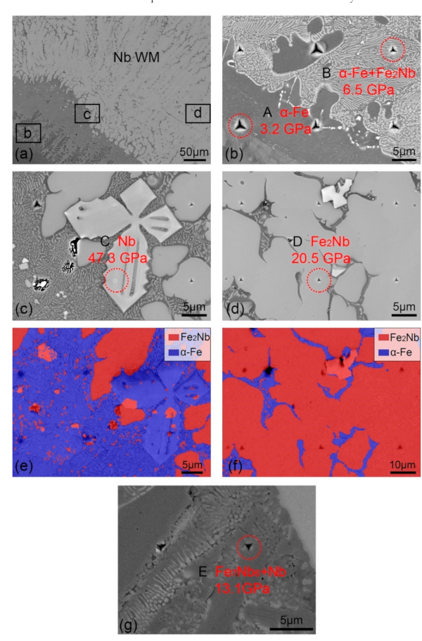
| Regions | Fe | Nb | Possible Phases | Hardness/GPa | Elastic Modulus/GPa |
|---|---|---|---|---|---|
| A | 98.60 | 1.40 | α-Fe | 3.2 | 206.5 |
| B | 89.68 | 10.32 | α-Fe + Fe2Nb | 6.5 | 206.5 |
| C | 10.12 | 89.88 | Nb | 47.3 | 378.9 |
| D | 69.55 | 30.45 | Fe2Nb | 20.5 | 275.3 |
| E | 45.36 | 54.64 | Fe7Nb6 + Nb | 13.1 | 176.1 |
Publisher’s Note: MDPI stays neutral with regard to jurisdictional claims in published maps and institutional affiliations. |
© 2021 by the authors. Licensee MDPI, Basel, Switzerland. This article is an open access article distributed under the terms and conditions of the Creative Commons Attribution (CC BY) license (http://creativecommons.org/licenses/by/4.0/).
Share and Cite
Chu, Q.; Zhang, L.; Xia, T.; Cheng, P.; Zheng, J.; Zhang, M.; Li, J.; Yan, F.; Yan, C. Microstructure and Fracture Toughness of Fe–Nb Dissimilar Welded Joints. Metals 2021, 11, 86. https://doi.org/10.3390/met11010086
Chu Q, Zhang L, Xia T, Cheng P, Zheng J, Zhang M, Li J, Yan F, Yan C. Microstructure and Fracture Toughness of Fe–Nb Dissimilar Welded Joints. Metals. 2021; 11(1):86. https://doi.org/10.3390/met11010086
Chicago/Turabian StyleChu, Qiaoling, Lin Zhang, Tuo Xia, Peng Cheng, Jianming Zheng, Min Zhang, Jihong Li, Fuxue Yan, and Cheng Yan. 2021. "Microstructure and Fracture Toughness of Fe–Nb Dissimilar Welded Joints" Metals 11, no. 1: 86. https://doi.org/10.3390/met11010086