Article

Sustainable Production of Powder Metallurgy Aluminum Foams Sintered by Concentrated Solar Energy

by
Antonio Cañadilla
1,
Ana Romero
2,* and
Gloria P. Rodríguez
1
1
E.T.S. Ingeniería Industrial, Institute of Energy Research and Industrial Applications, Universidad de Castilla-La Mancha (UCLM), 13071 Ciudad Real, Spain
2
Escuela de Ingeniería Industrial y Aeroespacial, Institute of Applied Aeronautical Industry Research, Universidad de Castilla-La Mancha (UCLM), 45071 Toledo, Spain
*
Author to whom correspondence should be addressed.
Metals 2021, 11(10), 1544; https://doi.org/10.3390/met11101544
Submission received: 16 July 2021 / Revised: 21 September 2021 / Accepted: 22 September 2021 / Published: 28 September 2021

Abstract

:
Porous aluminum foams were successfully fabricated following the space-holder powder metallurgy method with a solar sintering stage. Al foams with porosities of 50, 60, and 70 vol.% were sintered in a low-cost Fresnel lens. Green parts were prepared using aluminum powder as the main metallic material and saccharose as a soluble space-holder. The dissolution stage was designed for each foam and required longer periods of time, between 8 and 32 h, as the design porosity increased. Brown parts were fully sintered by concentrated solar energy at a lower temperature (500 °C) and for shorter times (12–20 min) than those required by conventional sintering techniques (640 °C, ~9 h). The evaluation of density and the characterization of pore size and distribution in the sintered foams was carried out. All obtained foams were stable and presented a homogeneously distributed porosity, very close to the design porosity, with differences lower than 2.1 vol.%, and with approximately half being characterized as open porosity. Moreover, the solar sintered foams presented a high quality, and similar or even greater mechanical properties (such as compressive strength and impact energy absorption) than those achieved by conventional techniques. Foams with 50 vol.% of porosity exhibited the best mechanical behavior, in terms of impact-energy absorption (24.42 MJ/m3) and compressive strength (27.4 MPa).

Graphical Abstract

1. Introduction

In recent years, many fields such as the automotive, aeronautical, and aerospace industries have been searching for safer and lighter energy-absorbing structural materials, as well as to achieve less pollutant gas emissions, higher fuel efficiency and better economy, among other benefits. The improvement of vehicle components’ energy absorption capabilities is very important in order to increase crashworthiness without increasing weight. Moreover, catastrophic failures in aerospace structures due to high-energy impact damages, such as the issues with the Columbia space shuttle, demonstrate the pressing need to use high-performance materials against impacts. Looking for these characteristics, advanced materials could reduce weight and improve strength, so many energy absorbers with different structures, such as type column, honeycomb, plates, and metallic foams, have been developed in recent years. For example, Abbasi et al. [1] achieved a high-energy absorption capacity structure by the design of 12-edge optimum section based on square, hexagonal and octagonal cross-sections columns. Considering sandwich structures (which are hybrid structures with a low-density core and two thin skin layers), Sun et al. [2] and Rong et al. [3] characterized the energy absorption behavior of sandwich structures with different geometric configurations, such as honeycomb and corrugated examples, respectively. Both works enhanced the core structure and the influence of geometry in the energy absorption capacity, deformation mechanisms, and mechanical behavior of the obtained parts. Tiwari et al. [4] and Liu et al. [5] studied the ballistic and energy absorption performance of thin aluminum and nickel-based alloy plates, respectively, and both investigations agreed the energy absorption capacity was greatly influenced by the velocity, size, and geometry of the ballistic impact, as well as the thickness, orientation, and geometry of the laminated plates.
Cellular solids can be used for many applications depending on the type of material used. For example, glass foams are used for thermal insulation, exploiting their low thermal conductivity, polymeric cellular structures are applied for packaging thanks to their good energy absorption, ceramic foams can be used as filters, etc. Metal foams exhibit novel mechanical, thermal, electrical, and acoustic properties, which allow these to be widely studied and used for numerous applications. One of the main interests in metal foams centers around their excellent energy absorption properties thanks to their special deformation mechanism. Banhart [6] showed that metal foams which convert impact energy into plastic work, and they possess higher specific strength and energy absorption performance than solid structures. This study also demonstrated that one of the unique advantages of metal foams is that parameters, such as pore size, density, geometry, and foaming material, could control the mechanical properties. The foams’ inner structures are directly related to the manufacturing process. Thus, foams can be classified as open foams (pores connected to each other, so fluids are able to pass through them), partially open foams, and closed foams (isolated closed pores filled with any fluid, mainly a gas). Rajak et al. [7] distinguished between them and their different applications: open cell foams are used in functional applications such as filters, heat exchangers, catalyst systems, etc., while closed and partially open foams are applied in structural applications like silencers, sound and energy absorbers, bearings, aerospace, aeronautic and automobile structures, construction materials, etc.
Over the last 20 years there has been a growing interest in development and use of light-weight aluminum foams. Simancik and Jerz [8] defined aluminum foams as relatively isotropic materials with a random and homogenous pore distribution in their inner structure that takes between 50 and 90% of the total volume and induces low densities that oscillate in the 0.4–1.2 g/cm3 range. Fuganti and Lorenzi [9] noticed Al foam absorb appreciable impact energy under quasi-static and dynamic loading by large plastic deformations and applied it to the design of sacrificial crash boxes for automobiles. Aluminum foams are used in structural and functional applications in the aeronautic, automotive, and construction sectors, thanks to their high specific strength and impact energy absorption properties despite their very low density. According to the study [10], the optimal and relative isotropic mechanical properties for these materials are achieved with high porosities between 82 and 95 vol.%, homogenous distribution of 0.02–0.12 mm2 pores, and densities close to 0.4 g/cm3. Moreover, Gutiérrez-Vázquez and Oñoro [11] determined that Al foams are highly efficient in terms of impact energy absorption, vibration and sound absorption, electromagnetic protection, and they remain stable at high temperatures and are not flammable. Wu et al. [12] assessed the thermal, corrosion resistance, and acoustic and vibration absorption properties, and reported that aluminum foams can be widely used in heat exchangers, thermal conductor surfaces, and noise absorption barriers owing to their high corrosion resistance and ease of recycling.
Regarding the production of aluminum foams, in the last 10 years there has been a huge improvement in the manufacturing techniques, meaning nowadays there are several methods available. Singh and Bhatnagar [13] classified the production methods of Al foams according to the initial state of the material, i.e., liquid metal, solid metal powder, gaseous phase metal or metal ions. Among these production methods, liquid metal and solid metal powder are the most described techniques with a wide range in total costs, qualities, and production capacities, such as melt-gas injection, melt-foaming, investment casting, melt infiltration, and powder metallurgy. Driven by cost effectiveness and parameter flexibility, powder metallurgy (PM) provides the manufacture of high-quality aluminum foams. The study [14] defined the sintering and dissolution process (SDP), which is based on the space-holder technique for the fabrication of Al foams, and emphasized the numerous advantages regarding the process and the results. The method starts with the uniaxial compaction of green components based on aluminum powder and soluble spacer mixture. Green parts are water-washed to dissolve the space-holder, giving rise to the brown parts. Finally, the brown specimens are sintered under inert atmosphere in a specific thermal cycle. One of the critical issues in this process is the selection of the appropriate space-holder since this controls the shapes and homogeneity of pores and their adequate distribution. Jiang et al. [15] fabricated open-cell aluminum foams with 50–80 vol.% porosities using carbamide as a space holder, and they found that the pore geometry depended on the shape and size distribution of the spacer. In the same way, Hussain and Suffin [16] achieved aluminum foams with porosity values in the range of 20–70 vol.% using NaCl particles as a soluble spacer. Compressive strength and energy absorption were not as good as desired due to the presence of residual brittle particles of NaCl in the pores, which stimulate corrosion during the sintering process.
In general terms, the resulting foams of applying the space-holder manufacturing technique show high quality interconnecting porosity with tight controlled process parameters. However, energy consumption and its resources are one of the current challenges. As such, the search for new energy sources and the efficient use of the energy are some of the most heavily researched and interesting goals. These elements form part of green economic policies, the objectives of which are high-efficiency production in industries and the protection of nature as well as people’s health and quality of life. Renewable energies encompass natural energy sources considered inexhaustible given that they are available in huge quantities or can be regenerated by natural processes. Regarding this definition, renewable energy resources include biofuels, geothermal, biomass, tidal power, wave power, hydropower, wind power, and solar energy. Historically, the primary interest of solar energy has been focused on the energy field, both electric and thermal. Nowadays, however, its application in science and metallurgy materials is the objective of numerous investigations thanks to the exploration and exploitation of concentrated solar energy (CSE).
CSE is one of the most promising clean and renewable energy resources, non-polluting and highly efficient for high temperature material processing. Concentrated solar energy is a strong alternative for materials processing and offers great potential in high temperature applications. Contrary to conventional processes where the higher the temperature needed, the higher the energy consumption, the costs of material processing using CSE are not dependent on the temperature. For high temperature processes and treatments, it provides high-energy density and competitiveness in cost terms, and thus could go head-to-head with modern technologies such as laser or plasma. As opposed to other renewable energy resources, like biofuels or biomass, CSE does not generate any CO2 or other contaminant agents, so atmosphere pollution and greenhouse effect are restricted.
Solar energy has shown great potential in thermal protection tests [17,18], heat treatments for microstructural modifications, such as solar hardening [19] and solar coating of steels [20], surface nitriding of titanium and its alloys [21], solar welding of steel [22], titanium alloys [23], or aluminum 5083-H11 [24], or even the sintering of different PM materials, such as steels or Ti6Al4V alloy. Metallic powders of M2 high-speed steel and of M2 reinforced with different vanadium carbide amounts were sintered using concentrated solar energy [25,26]. Good quality sintered parts at lower temperatures and shorter times than the necessary by conventional techniques were obtained in both studies. In another more recent study, Romero et al. [27] used a solar sinter-hardening process in Cr-Alloyed PM steels, achieving almost complete densities with only 15 min of holding time and the formation of bainitic and martensitic phases without the use of external cooling mediums. Kovacik et al. [28] carried out the solar sintering of titanium green parts and proved that sintering times were shorter than in the vacuum furnace while the observed porosities were below 5%, almost the same as those obtained in the vacuum furnace. Despite the positive results of CSE when applied to the sintering process of different metal alloys, there are not many studies about the use of this energy resource in the fabrication of metal foams or high porous structures. In this way, García et al. [29] tested titanium foams compacted from Ti powder and NaCl crystals and sintered in a 2 kW parabolic concentrator using CSE. They proved CSE heating appears to be an effective sintering process in terms of temperature and process time when it is applied in the space holder technique. The obtained Ti foams showed high quality and well controlled porosity, between 58 and 77 vol.%, with prismatic pores of 500–1000 µm, which presented a promising macropore and micropore structure for tissue engineering scaffold and implant applications. García-Cambronero et al. [30] used CSE in the foaming process of an AlSi12 alloy. The foaming treatment was faster and at lower temperatures than in electric furnaces thanks to the quick heat transmission from the air to the part. Moreover, Cambronero et al. [31] determined that carbonate precursors were easily foamed using CSE by a PM method, resulting in a lower risk of cell collapse than using conventional methods. Despite the fact these studies have shown advantageous results in the use of CSE in the production of Al foams by the foaming process, there is a lack of information to obtain Al foams by PM using a solar sintering stage, in accordance with the good results obtained using titanium foams [29].
It has been observed that solar energy has an activator effect in metal treatment, which results in shorter treatment times and a higher processing efficiency. If the solar concentration is carried out using a Fresnel lens, other positive aspects must also be considered. Facility and installation costs are very low, and overall costs are kept low independently of temperatures or time parameters, which makes the use of this kind of lens highly attractive for implementation in materials processing or microstructural and surface modifications. Regarding the great potential of solar energy applications in several metallurgical processes for aluminum and other materials, this work studies, for the first time, the feasibility of CSE application in aluminum sintering for the sustainable production of good quality aluminum foams that could be used as structural and functional materials. The process is carried out by a low-cost solar installation, Fresnel lens, and using the PM space-holder technique.

2. Materials and Methods

Aluminum foam fabrication started with the selection of the metal powder that will conform the metallic matrix, and water-soluble space holder that will translate the geometry and shape to the final porosity. Commercially pure aluminum powder with a purity of 99.5%, a maximum particle size of approximately 45 µm, and a melting temperature of 660.3 °C, according to Alfa-Aesar manufacturer specifications, was used. The aluminum powder used presents an irregular particle morphology with rounded edges and a wide size distribution as can be seen in Figure 1a. Commercially pure saccharose (C12H22O11) was provided by PanReac AppliChem (Barcelona, Spain), which was used as the space-holder material. According to the supplier, the saccharose presents a density of 1587 kg/m3, a particle size between 300 and 600 µm, a melting temperature of 186 °C and a water solubility at 20 °C of 1970 g/L, which are critical parameters in the debinding stage. The saccharose crystal particles present a prismatic geometry and sharp edges, as can be seen in Figure 1b. The significant difference between the saccharose and the metal powder particle diameter sizes enhances their adhesion and higher contact between them. The aluminum powder can completely surround and cover the saccharose particles. So, when the dissolution process takes place, the aluminum foams are able to maintain the inner geometry of the pores defined by the saccharose particles. In addition, ethanol was used as an organic binder for stimulating the powder adhesion on the space-holder faces during mixing. Ethanol (CH3CH2OH) with a purity of 99.8%, an ebullition temperature of 78.5 °C and a density of 0.789 kg/m3 was supplied by PanReac AppliChem (Barcelona, Spain).
Al foams were manufactured following the space-holder technique, in which aluminium powder was carefully mixed by hand with different saccharose amounts and a 1 wt.% of ethanol, until homogeneous mixtures were obtained. Foams with 50, 60, and 70 vol.% of soluble space holder were designed. Green cylindrical specimens of 16 mm in diameter and 5 mm in thickness were obtained by a Microtest ECH/400/SCM (Madrid, Spain) uniaxial press applying 200 MPa for 5 min.
The saccharose dissolution of the samples took place in two steps. Firstly, green parts were submitted to an iterative wash cycle to leach out the highest amount of saccharose particles. In each wash cycle, the parts were immersed in hot water at 60 °C for 1 h, under static conditions, and then dried at 80 °C for 2 h and weighed on a high-precision bascule. This process was repeated until the measured mass at the end of each iteration is stable, which is indicative that the dissolution of saccharose is complete. Finally, the samples were subjected to a final ethanol wash to ensure the complete removal of the space-holder, and then dried again in order to obtain the brown parts. After this last stage, the brown parts are very brittle and must be handled carefully so as not to break them.
Brown parts were sintered using CSE by an acrylic Fresnel lens of 900 mm in diameter and 31.7 mm thickness in its centre. The Fresnel lens has a ribbed surface, a refraction index of 1.49, and a transmission factor of 0.92. Thermal characterization of this installation was carried out in a previous work [32], which determined that the concentrated solar beam produces a focal spot (≈15 mm-in diameter) with a power density of up to 2640 kW/m2, which is approximately 2644 times the direct solar radiation of 1 kW/cm2 that usually incises in this location. The used solar spot size is adequate in order to treat the designed samples, without the need to carry out sweeps, which would be required in larger samples. Parts were placed inside a hermetic reaction chamber on an alumina bed to prevent overheating and temperature gradient along the vertical direction, as suggested [33]. The reaction chamber has a quartz cover to allow solar radiation to pass through and is refrigerated by a water circuit. A protective atmosphere of argon was used throughout the sintering process and was maintained for 10 min before and after the thermal process to avoid oxidation of the sample. Treatment temperature was registered by a K-type thermocouple in contact with the back surface of the brown part. It should be noted that a Fresnel lens like the one used in this study cost ~500 €, and the complete solar installation including the solar tracker ~6000 €. This price is independent of the temperature and the treatment time, since the price of the tests is practically free due to the fact it basically requires of the use of the CSE.
Figure 2a shows the Fresnel lens installation when a solar-sintering cycle is in operation, and Figure 2b exhibits in detail the sample placed on the alumina bed inside the reaction chamber. The sintering cycle starts when the part and the solar spot are well localized, and the protective atmosphere is stable. Firstly, the shutter of the solar facility is slightly opened to pre-heat the sample up to 250 °C for 5 min in order to avoid thermal cracks due to extreme warming rates, as explained by Romero et al. [34] in their study about the solar sintering of Ti foams. The shutter is then opened further to heat up and maintain the specimen at a maximum temperature plateau of 500–600 °C for 10–20 min. The temperatures recorded in a typical sintering cycle are shown in Figure 2c.
The microstructural quality of the final Al foams was evaluated using a LEICA DM IRM Optical Microscope (Wetzlar, Germany) and a JEOL J8M6500 Scanning Electron Microscope (Akishima, Tokyo, Japan). Porosity values were measured using the Archimedes method according to UNE-EN ISO 2738 [35], in which the masses of the sample in air and submerged in water are utilized for determining both total porosity and open porosity. The total porosity of the samples was also analysed via Leica MW QPhase software v3.1 (Leica Microsystems, Wetzlar, Germany), which identifies the different tonalities of the micrograph and, using an internal algorithm, groups them into a number of phases predetermined by the user. Several sections of the different samples have been studied via this software, identifying in them the amount of area with hollow spaces and that with material. After these analyses, a qualitative measure of the samples’ porosity was obtained.
The mechanical behaviour of Al foams was evaluated through compressive strength and impact energy absorption tests. Compressive strength, Young’s modulus, and specific strength characterization were evaluated by Microtest multiaxial equipment (Madrid, Spain) for tension/compression tests using a 50 kN loading cell in quasi-static conditions at a rate of 0.5 mm/min, according to UNE-EN ISO 4506 [36]. The impact energy absorption is measured by an INSTRON CEAST 9340 (Norwood, MA, USA) Impact Column according to UNE-EN ISO 5754 [37], using an impact energy of 5 J with a 10 mm diameter indenter that hits the specimen surface with an impact-speed of 2.86 m/s. It should be noted that the mean values and standard deviation measurements presented in this work are always the result of the evaluation of at least three samples processed in the same conditions.

3. Results and Discussion

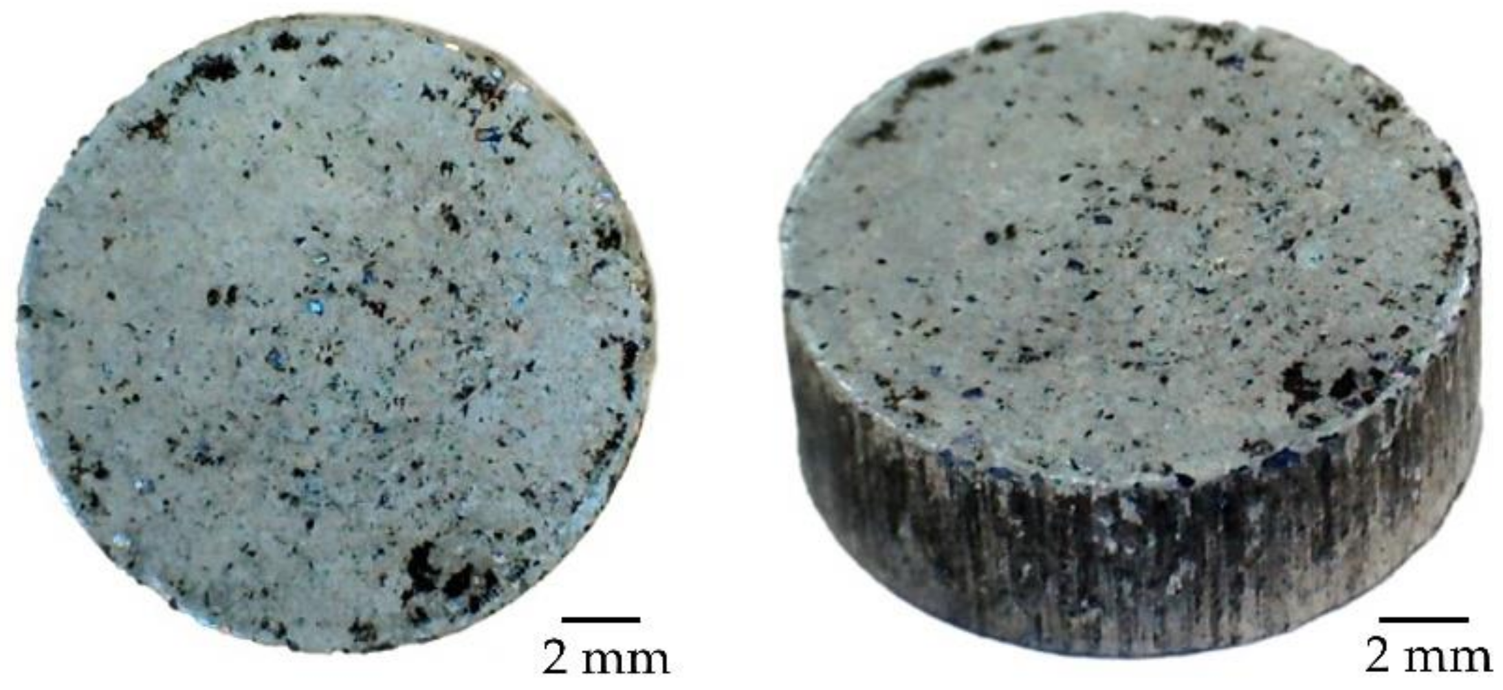
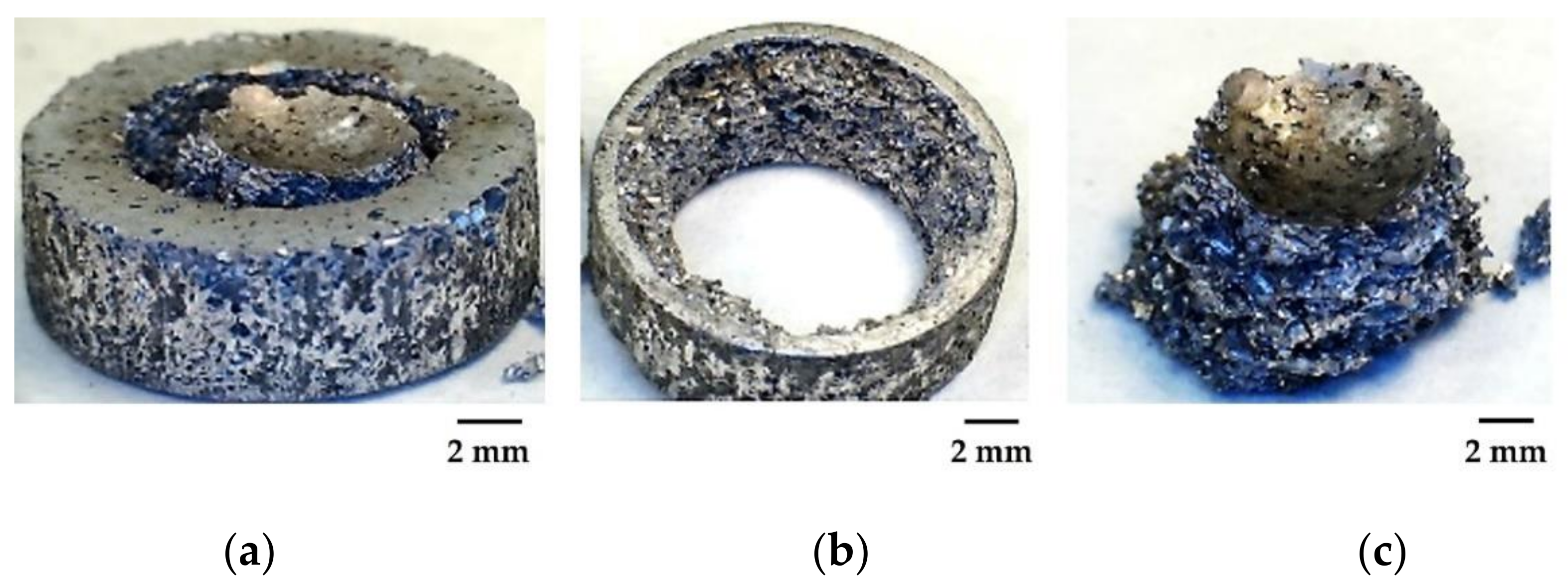
3.1. Foam Manufacturing

Green parts with design porosities of 50, 60, and 70 vol.% were processed using the space-holder powder metallurgy technique. The pressing stage has a direct influence in the quality of the aluminium green parts, so compaction pressure needs to be high enough to avoid collapses and maintain the foam shape in the subsequent stages, but not too high to prevent the fracture or distortion of the saccharose particles. Michailidis et al. [38] studied the compaction parameters and their influence in the manufacturing of Al foams with a design porosity of 50 vol.% using the space-holder technique. It established that a compaction pressure lower than 200 MPa could induce the spalling of Al powder from the spacer surface resulting in an imperfect geometry, and a compaction pressure higher than 300 MPa induced cracks in the samples, which compromised the following processing stages. Regarding these conclusions, the applied 200 MPa pressure in this study produced stable cylindrical green parts with a nominal diameter of 16 mm and a height of ~5 mm.
This study introduces time optimization in the dissolution stage, considering the water-solubility of saccharose which is 1970 g/L at 20 °C. The mass changes during the dissolution stage of all specimens are presented in Figure 3. The evaluation of time and debinding effectiveness in water of saccharose reveals that the higher the nominal foam porosity the faster the removal rate of spacer. Thus, foams with 70 vol.% design porosity were the first to complete the space-holder debinding, followed by those of 60 and finally those of 50 vol.% design porosity. This fact is due to the dissolution rate of a solute (saccharose) in a dissolvent (water) being directly proportional to the concentration of the first in the total volume of the second. Therefore, the necessary dissolving times for the complete space holder debinding were 32, 20, and 8 h, respectively, for Al foams with 50, 60, and 70 vol.% of design porosities.
All foams remained stable and without apparent geometrical changes during the washing process, although their mass decreased progressively. Moreover, final brown parts were strong enough to be handled even though most of the saccharose was dissolved in hot water. All the brown parts showed characteristics of a cellular material and very few remains or precipitates from the space-holder were appreciated in their surfaces, as can be seen in Figure 4 for the case of the foam with 70 vol.% design porosity, in which the highest space-holder amount was removed. It should be mentioned that if a low quantity of saccharose remained adhered to the pore’s surfaces, it could ultimately be debinded by sublimation in the first plateau at 250 °C of the sintering stage. Minimal differences were appreciated in the surface of the foams with different design porosity due to the increasing amount of saccharose. The foam with 70 vol.% design porosity was the one with the greatest number of cavities homogeneously distributed on its surface.
Zhao et al. [39] applied the space-holder PM technique for the fabrication of Al foams using NaCl as space-holder and concluded that NaCl dissolution is a significant limiting-rate stage, because it takes a long time to dissolve all the added salt due to the tortuosity of the foam structure. Moreover, any salt waste could cause damage and Al matrix corrosion during the sintering cycle due to its high reactivity. In the present study, thanks to the higher water-solubility of saccharose, the debinding times are lower and any residual saccharose particle can be removed during the sintering stage, predictably without any detrimental effect on the quality surface of the obtained Al foams.
The most novel stage in this study is the solar sintering that was carried out once the dissolution saccharose stage had been optimized. Several sintering cycles using a preheating plateau at 250 °C for 5 min and a maximum temperature plateau at 500, 550, and 600 °C for 10 min were performed in the Al foams of 50 vol.% design porosity. The Al foams sintered in these conditions are presented in Figure 5. Some molten aluminum oozed out, forming globules on the upper surface of the sample, and the cylindrical geometry was distorted in the foams sintered at 600 °C on the surface opposite to that of the incidence of the solar beam, as a result of an excessive sintering temperature in the exposed surface (Figure 5a). It should be noted that the temperature measurement was carried out on the surface opposite to the surface which is directly hit by the solar beam, so the real temperature in the rest of the sample is somewhat higher, which is why the sample melts. Beyond the geometrical changes, due to the melting and re-solidification of aluminum, the inner pores were saturated, and the design porosity of the foam was lost. A less severe aluminum partial melting was registered at 550 °C. In this case, the foams maintained their cylindrical geometry, but they presented little globules of melted aluminum on the upper surface and design porosity was also lost (Figure 5b). The foams sintered at a maximum temperature of 500 °C kept their shape and no melted parts or protuberances were found (Figure 5c). These foams present a homogeneous distribution of pores with prismatic geometry that fits with the shape of the saccharose particles. Therefore, 500 °C is considered as the adequate sintering plateau temperature.
On the other hand, the selection of an adequate sintering time depends on the design porosity of the foam, due to its influence on thermal conductivity. So, the sintering holding time needs to be longer as the design porosity of the foam increases. Hence, 10, 15 and 20 min were used as holding times for sintering of foams of 50, 60 and 70 vol.% design porosity, respectively. All the foams sintered in these conditions presented a strong and high-quality metallic appearance, no signs of melt, and they conserved their cylindrical shape, as can be seen in Figure 6 in the case of foam with 70 vol.% design porosity. Thus, the solar sintering parameters used are considered appropriate. Moreover, there are no signs of collapse of the edges or sides of the sintered parts, in any case, which shows the correct handling of the brown specimens between the debinding and sintering stages.
Table 1 presents the dimension and volume values of the parts in green and sintered states. The volume percentage variation is minimal in all cases (~0.02–0.03%), slightly increasing the height and keeping equal or slightly smaller the diameter of the sintered parts. Therefore, the Al foams obtained by the space-holder technique with a solar sintering stage fit accurately with the dimensions provided in the design stage, making this manufacturing method ideal for the fabrication of net-shape aluminum foam products.

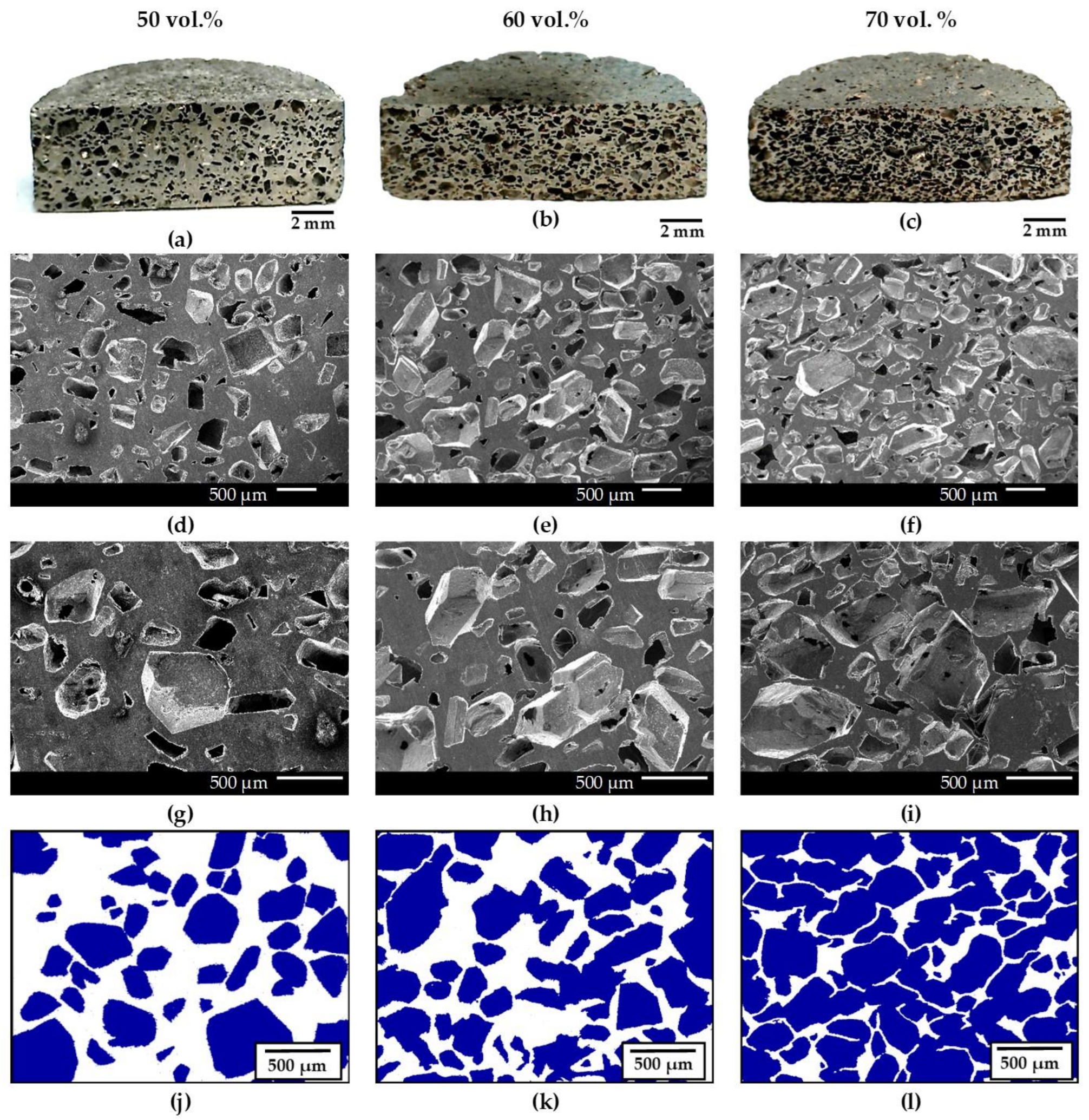
3.2. Porosity Analysis

Next, the porosity evaluation of the foams sintered at a maximum temperature of 500 °C and different holding times is carried out. A homogeneous pore distribution can be seen in the cross section of all the foams (Figure 7a–c). The number of pores increases progressively as the design porosity of the sample increases. However, from the macrographs there is no noticeable increase in the pore size. The adequate pore distribution and size observed across all the foams’ volume predicts isotropic behavior in the mechanical and functional sample properties. However, this fact should be verified by the corresponding tests.
The pores have a prismatic geometry and sizes between 500 and 1000 μm, which corresponds with the original shape and size of the saccharose crystals used (Figure 7d–f). The obtained pores had straight edges and sharp vertices, which could cause the initiation of cracks due to the stress concentration effect. The compaction pressure used (200 MPa) is under the mechanical strength of the saccharose particles, so no break or deformation evidence was determined prior to the debinding stage. It is thus demonstrated that the cell morphology and size of the final pores closely matched those of the saccharose particles used and there was no collapse or significant reduction of the pores during the pressing, saccharose dissolution or sintering stages. This means that the pore geometry and size in Al foams is well-controlled by the shape and size of the utilized space-holder, so these can be designed for different applications or to fit any specifications.
The pores coalesce resulting in a foam with open porosity, as can be seen at higher magnifications in Figure 7g–i, in which the details of the microporosity can also be better observed. In addition, it has also been possible to verify the high effectivity of solar treatment in the metallurgical join of the sintering channels, which was adequate in all the foams obtained. No relevant residual micro-porosity is localized in the aluminum sintering necks, which confirms the use of an appropriate sintering cycle. Next, the image analysis micrographs are shown in order to highlight the difference between the sintering necks (in white) and the macropores obtained from the saccharose particles (in blue) (Figure 7j–l). These images also show the increment of porosity as design porosity increases, that the pore geometry remains stable, and that the porosity is homogeneous in the entire section. The width of the sintering necks is shorter as the porosity of the foam increases, and it is reasonably homogeneous across different sections of the same foam. All this evidence confirms the great potential of this manufacturing technique for well-controlled porosity Al foams, or even metallic cellular materials in general.
To analyze the distribution and average value of pore size in the foams designed with three different levels of porosity, a multitude of pore size measurements have been taken in different sections of each sample. The chosen measure of each analyzed pore was the most representative dimension. These results are presented in Figure 8, in which each point corresponds to one pore size measure. It should be noted that, in addition to the pores obtained from the addition of space-holder particles, other macropores appeared due to the aggregation of two or more adjacent pores which cause open porosity, especially in the samples with the highest porosity levels. In the case of foams with a design porosity of 50 vol.% (Figure 8), the pores have an average size of 517 µm, which is in the size range of the saccharose particles used (200–600 µm). This means that space-holder particles are the main cause of the pores forming. The average pore size was 819 and 1017 µm respectively for the foams with design porosities of 60 and 70 vol.% (Figure 8). Therefore, the pore size increases in line with the increasing of the design porosity value, so the joining and aggregation of adjacent pores in interconnected cavities is confirmed.
In addition to the average pore size, Figure 8 also shows information about the variability of pore size measurements, both quantitatively through the typical deviation value and qualitatively by the dispersion of the values. Aluminum foams with a design porosity of 50 vol.% (Figure 8) exhibit the lowest typical deviation (152 µm) and a pore-size measurement dispersion typical of the own variability of the saccharose particles size used as space-holder, validating the previous results. The foams with 60 and 70 vol.% of design porosity (Figure 8) present a higher dispersion of ~220 µm in both cases, which is justified by the aggregation of adjacent pores. So, it can be concluded that both the selection of space-holder and design porosity are the principal parameters that influence the pore geometry, size, and distribution.
The density values of all the sintered Al foams were measured by the Archimedes method to determine the total and open porosity, and the obtained results are presented in Table 2. The average porosity values were 52.1, 60.8, and 70.1 vol.% for the foams designed with porosities of 50, 60, and 70 vol.%, respectively. The porosity value measured in the sintered foams was very stable and was always in line with the design porosity value, which validates this powder metallurgical technique for the manufacture of Al foams using saccharose as a space-holder. Al foams presented 17.2, 26.3, and 37.9 vol.% of interconnected porosity, which is ~33, 43, and 54% of the total porosity. This fact confirms that the higher the total amount of porosity in the foam, the higher the percentage of open porosity, since the cubic and irregular geometry of the used saccharose particles favors the pore aggregation and the formation of open porosity channels. Conversely, the use of spheric space-holder particles promotes the formation of a more closed porosity, as Idris et al. [40] reported in their study about the manufacturing of closed-cell aluminum foams in which carbamide was used as a space holder.
The interconnected porosity through the adjacent pores and the open porosity channels can be appreciated in more detail in Figure 9, which shows the pores at ×250 and the inner surfaces details of pore walls at ×500. In all cases, cell walls are very densified and present a low number of micro-pores or interstices, which denotes that a strong bonding and good integrity among aluminum particles have been achieved after the sintering. Kennedy [41] and Torres and Pavón [42] also studied the open interconnected porosity in metallic foams and concluded, as in this work, that open porosity is more likely to appear when the used space holder proportion is 50 vol.% or more, as this sees bigger cavities and thinner metallic walls obtained.
The results presented in this study and in other previous work based on the fabrication of cellular metal materials [43] have shown that foams obtained by the space-holder technique can be designed in a wide range of porosities, typically from 50 to 80 vol.%, which is difficult to achieve by other foam manufacturing processes such as preform infiltration. This work has also demonstrated that this manufacturing technique is very flexible and versatile, adapts adequately to the design porosity of the foams, and allows extensive control of the resulting open porosity, which is a desirable characteristic in many functional applications.

3.3. Mechanical Properties Evaluation

After the porosity evaluation of the foams, mechanical tests were carried out. Strain is defined as a nominal value, since it is not the real strain experienced by the foams. Due to the geometry of the parts, it was not possible to use any strain measurement equipment. Banhart and Baumeister [44] studied the mechanical properties of different metal alloys foams, including Al foams, and proved that they exhibit the same stress–strain curve stages of cellular solids as defined by Gibson and Ashby [45]: linear elastic deformation stage, plateau deformation stage, and densification stage.
Figure 10 shows an example of the stress–strain curve, registered during a compression test of an aluminum foam with 60 vol.% of design porosity, identifying the different stages. Firstly, a lineal increase in stress and strain can be observed for low compression loads, which seems to indicate an elastic behavior. However, Jiang and Zhao [15] revealed that this increase is only partially reversible due to the irreversible deformation processes that occur in the foam structure, so the Young’s modulus can only be determined in an approximate manner. Secondly, the curve change into the plateau stage, where there is very significant plastic deformation characterized by a small slope of the stress–strain ratio, in some cases even becoming completely horizontal. This stage is attributed to the notable distortion suffered by the pore walls. Thirdly and finally, the slope gradually switches to the densification stage, when a relevant increase is registered in the stress as the pore walls start touching each other.
The magnitude of the stress–strain curve depends on the foam porosity, but the evolution has been the same in all sintered Al foams (Figure 11). It can be observed that decreasing the porosity of the foam increases compressive strength. In this work, all the registered curves show an upper yield point, before the plateau stage, which was selected as the compressive strength of the foam. From the stress–strain curves of the foams, the compressive strength, average effective Young’s modulus or structural stiffness, and specific strength (knowing the samples’ mass) values have been determined, as included in Table 3. It should be noted that, as has been proposed in previous foam research [46,47], the term effective elastic modulus has been used due to the fact the material is not isotropic. As is observed, the compressive strength values decrease in accordance with the increasing porosity of the foam, at 27.5, 16.5, and 7.5 MPa for the foams with design porosity of 50, 60, and 70 vol.%, respectively. The highest strength values obtained in the Al foams designed with 50 vol.% porosity reveals the significant influence of the thickness of metallic walls (which conform the aluminium matrix) in the mechanical behaviour of the material. The same decreasing tendency as porosity increases occurs with the specific compressive strength, where the mass of the foams with different porosity percentages are considered. The mean values of the specific strength are 20.4, 16.2, and 9.4 MPa/g for foams with design porosities of 50, 60, and 70 vol.%, respectively. It should be noted that the nominal and specific compressive strength values achieved in this study are similar to those obtained in previous work about aluminium foams manufactured by conventional PM methods. Xudong et al. [48] achieved compressive strengths of 29.38, 18.80, and 9.85 MPa for Al foams with 50, 60, and 70 vol.% of porosity obtained by the space-holder technique and conventional sintering.
The average elastic modulus of the Al foam decreases when the porosity increases, being 313.2, 281.6, and 116.7 MPa for the design porosities of 50, 60, and 70 vol.%, respectively. Xiao-Quing et al. [49] tested Al foams with 60 vol.% of porosity and different pore size of 2.50, 1.50, and 0.75 mm, which presented elastic modulus values of 218, 228, and 280 MPa, respectively. It was concluded that foams with smaller pore size produced a Young’s modulus greater than foams with larger pore size. The Young’s modulus values obtained in this work in the Al foams with 60 vol.% of porosity and ~800 µm of pore size (281.61 MPa) are similar and even slightly higher than those obtained in the previous study.
The energy absorption against impact is one of the most highly demanded characteristics in porous metallic structures. The long plateau deformation stage that Al foams exhibited in the compressive tests confirmed their high deformation capacity, which is directly related to their energy-absorption capability. However, the energy absorption was measured by column impact tests. As with the example for the fracture evaluation, photographs of a same sample after the impact test are presented in Figure 12. It can be seen how the foam surface, which the indenter impacted with the selected speed and energy, absorbed the impact energy through the deformation of the pore walls that make up the foam structure (Figure 12a). Since the impact-energy absorption capacity of the foam is exceeded, the pore walls start to fracture in a ductile manner until the porous structure is completely broken, parallel to the impact direction, showing significant plastic deformation (Figure 12b,c).
The impact energy absorption value of each specimen is considered as the total energy absorption at a strain of 60%, as was reported in a previous work which determined the energy absorption characteristics of open-cell aluminium foams fabricated with SDP and NaCl as space-holders [48]. An energy absorption of 20.91, 13.45, and 6.57 MJ/m3 was obtained in this previous work for Al foams with a homogenous porosity of 50, 60, and 70 vol.%, respectively. The impact energy absorption results obtained in the present study are collected in Table 4, which were of 24.57, 16.39, and 10.78 MJ/m3 for the foams with 50, 60, and 70 vol.% of design porosities, respectively. As can be observed, the energy absorption of Al foams decreases when the porosity increases, since this causes the pore walls to be thinner and therefore weaker. In this sense, Al foams with 50 vol.% of porosity showed the highest energy absorption capacity and a strong structure with high mechanical properties while maintaining a low weight. Miyoshi et al. [50] investigated the energy absorption of Al foams with 60 vol.% of porosity and revealed 4.97 MJ/m3 and 1.80 MJ/m3 for foams with a mean pore size of 1.50 and 2.50 mm, respectively. It was concluded that the energy absorption properties could be enhanced by an increase in the aspect ratio of the cell wall thickness and the reduction of cell size. In the present study, Al foams with 60 vol.% of design porosity and ~800 µm of pore size achieved a considerably higher energy absorption capacity (16.42 MJ/m3), thanks both to a smaller pore size and the high-quality surfaces and brightness of the foams obtained after solar sintering process. Therefore, the Al foams manufactured in this work present better energy-absorption behaviour than the parts fabricated by conventional sintering, so it can be concluded that solar-processed aluminium foams have higher impact resistance.

4. Conclusions

The fabrication of high-quality and brightness aluminum foams with adequate microstructures and mechanical properties has been achieved by the space-holder PM technique and a solar sintering stage. The primary accomplishments obtained are presented below.
  • Saccharose is an excellent spacer for the fabrication of aluminum foams which allowed the obtention of high-quality Al foams without damage after the manufacturing process. In addition, it has allowed the attainment of foams with final porosities very close to the design porosity, with maximum differences of 2.1%. Increasing the amount of saccharose particles increases the foam porosity, including open porosity, permitting control of the size and geometry of the porosity of the resulting foams, which always showed a homogeneous pore distribution.
  • The space-holder debinding stage through water dissolution is effective, since no remaining saccharose particles are detected and the mass remains stable after the last wash cycle, and its duration depends on the nominal design porosity. Aluminum foams with higher porosity percentage (60 and 70 vol.%), have shorter dissolution processes, e.g., as low as 8 h in the case of the foams with 70 vol.% of design porosity.
  • Solar sintering is a sustainable, clean, and highly efficient energy process that has allowed for the reduction of conventional sintering times of aluminum foams (habitually higher than 9 h) to just 30 min. The use of an argon protective atmosphere was sufficient in preventing the oxidation and contamination of the material during the sintering cycle. The use of more expensive reducing atmospheres such as N2-H2, which are habitual in conventional procedures, was unnecessary.
  • Aluminum foams sintered by CSE exhibited similar or even higher mechanical properties than Al foams fabricated by conventional methods. The compressive stress– strain curves obtained were very stable and reflected that the compressive strength decreases when the foam porosity increases. Aluminum foams with a design porosity of 50 vol.% presented the highest energy absorption values in the impact test and a strong aluminum matrix structure which lends them high mechanical properties, specifically high compressive strength and low weight, which makes them very appealing and potentially applicable.
The use of concentrated solar energy in the processing of aluminum foams has allowed the sintering to occur in just 30 min, obtaining high quality structures in terms of appearance surface, microstructure, and mechanical properties, with porosities very close to those of the design. This research highlights and promotes the wide possibilities of the use of concentrated solar energy in metal treatment at high temperatures because it is an ecofriendly and high-performance processing technique which allows for the efficient and sustainable production of components, and often the improvement of the final properties of the parts.

Author Contributions

Conceptualization, G.P.R. and A.R.; methodology and investigation, A.C. and A.R.; data curation, A.C.; writing—original draft, A.C. and A.R.; visualization, A.C.; supervision, A.R. and G.P.R.; funding acquisition. G.P.R.; writing—review and edition, A.R. and G.P.R. All authors have read and agreed to the published version of the manuscript.

Funding

The authors would like to acknowledge the financial support from the Castilla-La Mancha Government (JCCM) under research grants (SBPLY/19/180501/000170) co-financed by the ERDF (European Regional Development Fund) and by University of Castilla-La Mancha (Grants no. 2020-GRIN-28943 and 2021-GRIN-31096).

Institutional Review Board Statement

Not applicable.

Informed Consent Statement

Not applicable.

Data Availability Statement

The data presented in this study are available on request from the corresponding author.

Conflicts of Interest

The authors declare no conflict of interest.

References

  1. Abbasi, M.; Reddy, S.; Ghafari-Nazari, A.; Fard, M. Multiobjective crashworthiness optimization of multi-cornered thin-walled sheet metal members. Thin-Walled Struct. 2015, 89, 31–41. [Google Scholar] [CrossRef]
  2. Sun, G.; Chen, D.; Huo, X.; Zheng, G.; Li, Q. Experimental and numerical studies on indentation and perforation characteristics of honeycomb sandwich panels. Compos. Struct. 2018, 184, 110–124. [Google Scholar] [CrossRef]
  3. Rong, Y.; Liu, J.; Luo, W.; He, W. Effects of geometric configurations of corrugated cores on the local impact and planar compression of sandwich panels. Compos. B Eng. 2018, 152, 324–335. [Google Scholar] [CrossRef]
  4. Tiwari, G.; Iqbal, M.A.; Gupta, P.K. Energy absorption characteristics of thin aluminium plate against hemispherical nosed projectile impact. Thin-Walled Struct. 2018, 126, 246–257. [Google Scholar] [CrossRef]
  5. Liu, J.; Zheng, B.; Zhang, K.; Yang, B.; Yu, X. Ballistic performance and energy absorption characteristics of thin nickel-based alloy plates at elevated temperatures. Int. J. Impact Eng. 2019, 126, 160–171. [Google Scholar] [CrossRef]
  6. Banhart, J. Manufacture, characterisation and application of cellular metals and metal foams. Prog. Mater. Sci. 2001, 46, 559–632. [Google Scholar] [CrossRef]
  7. Rajak, D.K.; Kumaraswamidhas, L.A.; Das, S. An energy absorption behaviour of foam filled structures. Proc. Mater. Sci. 2014, 5, 164–172. [Google Scholar] [CrossRef] [Green Version]
  8. Simancik, F.; Jerz, J. Aluminium foam: A new light weight structural material. Metall. Mater. 1997, 35, 187–194. [Google Scholar] [CrossRef]
  9. Fuganti, A.; Lorenzi, L.; Gronsund, A.; Langseth, M. Aluminium foam for automotive applications. Adv. Eng. Mater. 2000, 2, 200–204. [Google Scholar] [CrossRef]
  10. Chen, C.; Fleck, N.A.; Lu, T.J. The mode I crack growth resistance of metallic foams. J. Mech. Phys. Solids 2001, 49, 231–259. [Google Scholar] [CrossRef]
  11. Gutiérrez-Vázquez, J.A.; Oñoro, J. Espumas de aluminio. Fabricación, propiedades y aplicaciones. Rev. Metal. 2008, 44, 457–476. [Google Scholar] [CrossRef]
  12. Wu, Z.; He, D.P.; Song, Z.L.; Ma, L.Q. Effects of viscosity on cellular structure of foamed aluminum in foaming process. Sci. Bull. 2000, 45, 348–352. [Google Scholar] [CrossRef]
  13. Singh, S.; Bhatnagar, N. A survey of fabrication and application of metallic foams (1925–2017). J. Porous Mater. 2018, 25, 537–554. [Google Scholar] [CrossRef]
  14. Zhao, Y.Y.; Sun, D.X. A novel sintering-dissolution process for manufacturing Al foams. Scr. Mater. 2001, 44, 105–110. [Google Scholar] [CrossRef] [Green Version]
  15. Jiang, B.; Zhao, N.Q.; Shi, C.S.; Li, J.J. Processing of open cell aluminum foams with tailored porous morphology. Scr. Mater. 2005, 53, 781–785. [Google Scholar] [CrossRef]
  16. Hussain, Z.; Suffin, N.S.A. Microstructure and mechanical behaviour of aluminium foam produced by sintering dissolution process using NaCl space holder. J. Eng. Sci. 2011, 7, 37–49. [Google Scholar]
  17. Kovacik, J.; Emmer, S.; Rodriguez, J.; Cañadas, I.S. Solar furnace: Thermal shock behavior of TiB2 coating on steel. In Proceedings of the International Conference on Metallurgy and Materials, Brno, Czech Republic, 21–23 May 2014; pp. 863–868. [Google Scholar]
  18. Van den Abeelen, L. Spaceplane HERMES: Europe’s Dream of Independent Manned Spaceflight, 1st ed.; Springer Praxis Books; Springer: Hilversum, The Netherlands, 2017. [Google Scholar]
  19. Pantelis, D.I.; Griniari, A.; Sarafoglou, C. Surface alloying of pre-deposited molybdenum-based powder on 304L stainless steel using concentrated solar energy. Sol. Energy Mater. Sol. Cells 2005, 89, 1–11. [Google Scholar] [CrossRef]
  20. Sánchez Bautista, C.; Ferriere, A.; Rodríguez, G.P.; López-Almodóvar, M.; Barba, A.; Sierra, C.; Vázquez, A.C. NiAl intermetallic coatings elaborated by a solar assisted SHS process. Intermetallics 2006, 14, 1270–1275. [Google Scholar] [CrossRef]
  21. Rodríguez, G.P.; Herranz, G.; Romero, A. Solar gas nitriding of Ti6Al4V alloy. App. Surf. Sci. 2013, 283, 445–452. [Google Scholar] [CrossRef]
  22. Romero, A.; García, I.; Arenas, M.A.; López, V.; Vázquez, A. High melting point metals welding by concentrated solar energy. J. Sol. Energy 2013, 95, 131–143. [Google Scholar] [CrossRef] [Green Version]
  23. Romero, A.; García, I.; Arenas, M.A.; López, V.; Vázquez, A. Ti6Al4V titanium alloy welded using concentrated solar energy. J. Mater. Process. Technol. 2015, 223, 284–291. [Google Scholar] [CrossRef]
  24. Karalis, D.G.; Pantelis, D.I.; Daniolos, N.M.; Bougiouri, V.D.; Rodríguez, J.; Karakizis, P.N.; Kazasidis, M.E. An attempt of 5083–H111 aluminum alloy welding using variable concentrated solar energy. In Proceedings of the 6th ICMEN International Conference, Tessaloniki, Greece, 5–6 October 2017; pp. 1–10. [Google Scholar]
  25. Herranz, G.; Romero, A.; de Castro, V.; Rodríguez, G.P. Development of high speed steel sintered using concentrated solar energy. J. Mater. Process. Technol. 2013, 213, 2065–2073. [Google Scholar] [CrossRef]
  26. Herranz, G.; Romero, A.; de Castro, V.; Rodríguez, G.P. Processing of AISI M2 high speed steel reinforced with vanadium carbide by solar sintering. Mater. Des. 2014, 54, 934–946. [Google Scholar] [CrossRef]
  27. Romero, A.; Rodríguez, G.P.; Barea, R. Sinter-hardening of chromium PM steels with concentrated solar energy. J. Mater. Process. Technol. 2020, 280, 116–616. [Google Scholar] [CrossRef]
  28. Kovacik, J.; Emmer, S.; Rodríguez, J.; Cañadas, I. Sintering of HDH Ti powder in a solar furnace at Plataforma Solar de Almería. J. Alloy. Compd. 2017, 695, 52–59. [Google Scholar] [CrossRef]
  29. García, I.; Gracia-Escosa, E.; Bayod, M.; Conde, A.; Arenas, M.A.; Damborenea, J.; Romero, A.; Rodríguez, G. Sustainable production of titanium foams for biomedical applications by concentrated solar energy. Mater. Lett. 2016, 185, 420–423. [Google Scholar] [CrossRef]
  30. García-Cambronero, L.E.; Cañadas, I. Foaming of aluminium-silicon alloy using concentrated solar energy. Sol. Energy 2010, 84, 879–887. [Google Scholar] [CrossRef]
  31. Cambronero, L.E.G.; Cañadas, I.; Diaz, J.J.; Ruiz Román, J.M.; Martinez, D. Properties of aluminium nodules foamed with concentrated solar energy. In Proceedings of the Euro International Powder Metallurgy Congress and Exhibition (Euro PM 2011), Barcelona, Spain, 9–12 October 2011; Volume 2, pp. 339–344. [Google Scholar]
  32. Ferriere, A.; Rodríguez, G.P.; Sobrino, J.A. Flux distribution delivered by a Fresnel lens used for concentrating solar energy. J. Sol. Energy. Eng. 2004, 126, 654–660. [Google Scholar] [CrossRef]
  33. Arnold, M.; Kroner, C.; Singer, R.F. PM aluminium foams: Stabilizing mechanisms and optimisation. In Proceedings of the 3rd International Conference on Cellular Metals and Metal Foaming Technology, Berlin, Germany, 23–25 June 2003; Volume 25, pp. 371–376. [Google Scholar]
  34. Romero, A.; Rodríguez, G.P. Sinterización de espumas de titanio en un horno solar parabólico. Rev. Soc. Esp. Mater. 2018, 2, 18–21. [Google Scholar]
  35. UNE-EN ISO 2738:2000, Materiales Metálicos Sinterizados, Excepto Metal Duro. Determinación de la Densidad, Contenido de Aceite Y Porosidad. 2000. Available online: https://tienda.aenor.com/norma-une-en-iso-2738-2000-n0023097 (accessed on 27 September 2021).
  36. UNE-EN ISO 4506:2018, Materiales Metálicos Sinterizados, Excepto Metal Duro. Ensayo de Compresión. 2018. Available online: https://www.en.aenor.com/normas-y-libros/buscador-de-normas/une/?c=N0060628 (accessed on 27 September 2021).
  37. UNE-EN ISO 5754:2017, Materiales Metálicos Sinterizados, Excepto Metal Duro. Probeta Sin Entalla Para Ensayo de Impacto. 2017. Available online: https://tienda.aenor.com/norma-une-en-iso-5754-2018-n0059736 (accessed on 27 September 2021).
  38. Michailidis, N.; Stergioudi, F. Establishment of process parameters for producing Al-foam by dissolution and powder sintering method. Mater. Des. 2011, 32, 1559–1564. [Google Scholar] [CrossRef]
  39. Zhao, Y.; Han, F.; Fung, T. Optimization of compaction and liquid-state sintering in sintering and dissolution process for manufacturing Al-foams. Mater. Sci. Eng. 2004, 364, 117–125. [Google Scholar] [CrossRef] [Green Version]
  40. Idris, M.I.; Ehsan, I.I.; Mohamed, S.H. Effect of organic space holder in fabrication of closed-cell aluminium foam. Trans. Tech. Publ. 2014, 594, 780–785. [Google Scholar] [CrossRef] [Green Version]
  41. Kennedy, A. Porous metals and metal foams made from powders. Powder Metall. 2012, 124, 33060. [Google Scholar] [CrossRef] [Green Version]
  42. Torres, Y.; Pavón, J.; Rodríguez, J.A. Processing and characterization of porous titanium for implants by using NaCl as space holder. J. Mater. Process. Technol. 2012, 212, 1061–1069. [Google Scholar] [CrossRef]
  43. Sun, D.X.; Zhaoc, Y.Y. Static and dynamic energy absorption of Al foams produced by the sintering and dissolution process. Metall. Mater. Trans. B 2003, 34, 69–74. [Google Scholar] [CrossRef]
  44. Banhart, J.; Baumeister, J. Deformation characteristics of metal foams. J. Mater. Sci. 1998, 33, 1431–1440. [Google Scholar] [CrossRef]
  45. Gibson, L.J.; Ashby, M.F. Cellular Solids: Structure & Properties; Pergamon Press: Oxford, UK, 1988. [Google Scholar] [CrossRef]
  46. Szlancsik, A.; Katona, B.; Dombóvári, Z.; Orbulov, I.N. On the effective young’s modulus of metal matrix syntactic foams. Mater. Sci. Technol. 2017, 33, 2283–2289. [Google Scholar] [CrossRef]
  47. Orbulov, I.N.; Szlancsik, A. On the mechanical properties of aluminum matrix syntactic foams. Adv. Eng. Mater. 2018, 20, 1700980. [Google Scholar] [CrossRef] [Green Version]
  48. Yang, X.; Hu, Q.; Du, J.; Song, H.; Zou, T.; Sha, J.; He, C.; Zhao, N. Compression fatigue properties of open-cell aluminium foams fabricated by space-holder method. Int. J. Fatigue 2019, 121, 272–280. [Google Scholar] [CrossRef]
  49. Cao, X.Q.; Wang, Z.H.; Ma, H.W.; Zhao, L.M.; Yang, G.T. Effects of cell size on compressive properties of aluminium foam. Trans. Nonferr. Met. Soc. China 2006, 16, 351–356. [Google Scholar] [CrossRef]
  50. Miyoshi, T.; Elnasri, I.; Pattofatto, S.; Zhao, H.; Tsitsiris, H.; Hild, F.; Girard, Y. Shock enhancement of cellular structures under impact loading: Part I experiments. Scr. Mater. 1999, 41, 1055–1060. [Google Scholar] [CrossRef]
Figure 1. SEM micrographs of (a) pure aluminium powder (×1500) and (b) saccharose particles (×30).
Metals 11 01544 g001
Figure 2. (a) Fresnel lens. (b) Reaction chamber and brown part localized in the alumina bed. (c) Sintering cycle.
Metals 11 01544 g002
Figure 3. Saccharose dissolving rate for different design porosity foams.
Metals 11 01544 g003
Figure 4. Al foam with 70 vol.% of design porosity in brown state.
Metals 11 01544 g004
Figure 5. Foams designed with 50 vol.% porosity, sintered at a maximum temperature of (a) 600 °C, (b) 550 °C and (c) 500 °C.
Metals 11 01544 g005
Figure 6. Sintered Al foams with 70 vol.% design porosity.
Metals 11 01544 g006
Figure 7. (ac) Macrographs; SEM micrographs (df) ×30 (gi) ×50; (jl) Image Analysis micrographs. Al foams with design porosities of (a,d,g,j) 50 vol.%, (b,e,h,k) 60 vol.% and (c,f,i,l) 70 vol.%.
Metals 11 01544 g007
Figure 8. Dispersion and average pore size value in Al foams with 50, 60 and 70 vol.% of design porosity.
Metals 11 01544 g008
Figure 9. SEM micrographs of pore inner surfaces of the sintered Al foams with design porosities of (ad) 50 vol.% (be) 60 vol.% and (cf) 70 vol.%.
Metals 11 01544 g009
Figure 10. Stages of a typical stress-strain curve registered in an Al foam with 60 vol.% of design porosity.
Metals 11 01544 g010
Figure 11. Stress-strain curves of Al foams with different porosities.
Metals 11 01544 g011
Figure 12. Al foam after impact test. (a) Sample directly extracted from the column impact machine. (b) Detail of foam portion that did not suffer the indenter impact directly. (c) Detail of foam portion that suffered the indenter impact directly.
Metals 11 01544 g012
Table 1. Dimensional analysis of the foams.
Design PorosityGreen StateSintered State%Var.
(vol.%)Diameter (mm)H (mm)Vol. (cm3)Diameter (mm)H (mm)Vol. (cm3)Vol. (cm3)
5016.00 ± 0.105.00 ± 0.101.00 ± 0.0115.97 ± 0.095.14 ± 0.101.03 ± 0.020.03
6015.93 ± 0.105.12 ± 0.111.02 ± 0.020.02
7015.96 ± 0.045.16 ± 0.021.03 ± 0.010.03
Table 2. Porosity values of sintered Al foams.
Al Foam50 vol.%60 vol.%70 vol.%
Porosity (%)Total52.1 ± 1.660.8 ± 1.670.1 ± 0.9
Open17.2 ± 0.926.3 ± 0.837.9 ± 0.8
Table 3. Parameters measured and properties evaluated in aluminium foams.
Design Porosity50 vol.%60 vol.%70 vol.%
σcomp (MPa)27.4 ± 0.716.5 ± 0.97.5 ± 1.5
Mass (g)1.33 ± 0.031.05 ± 0.030.79 ± 0.02
σ’comp (MPa/g)20.6 ± 0.915.7 ± 1.29.5 ± 1.9
Effective E (MPa)313.2 ± 10.7281.6 ± 10.2116.7 ± 16.8
Table 4. Energy absorption values of the aluminium foams.
Design Porosity50 vol.%60 vol.%70 vol.%
Eabs (MJ/m3)24.42 ± 0.4416.42 ± 0.8810.69 ± 1.43
Publisher’s Note: MDPI stays neutral with regard to jurisdictional claims in published maps and institutional affiliations.

