
Accelerated Spheroidization of Cementite in Sintered Ultrahigh Carbon Steel by Warm Deformation


Abstract
:1. Introduction
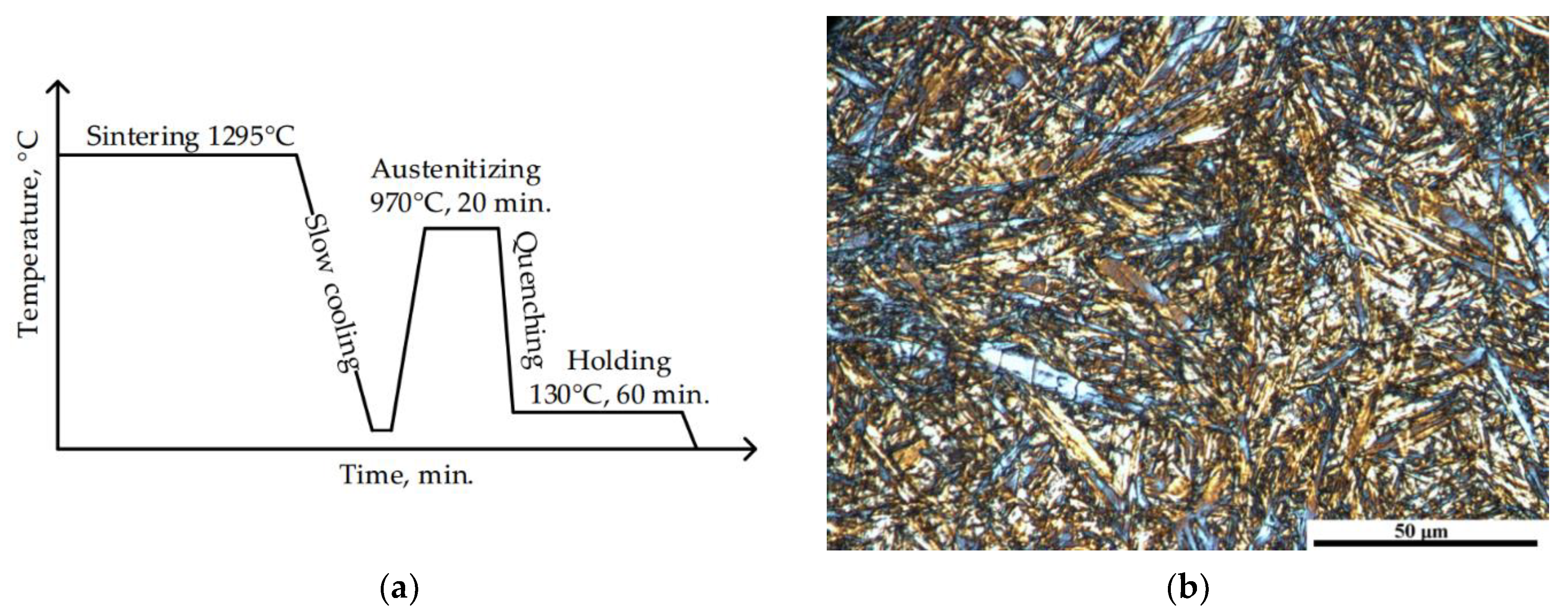
2. Materials and Methods
3. Results
3.1. Stress-Strain Relationships
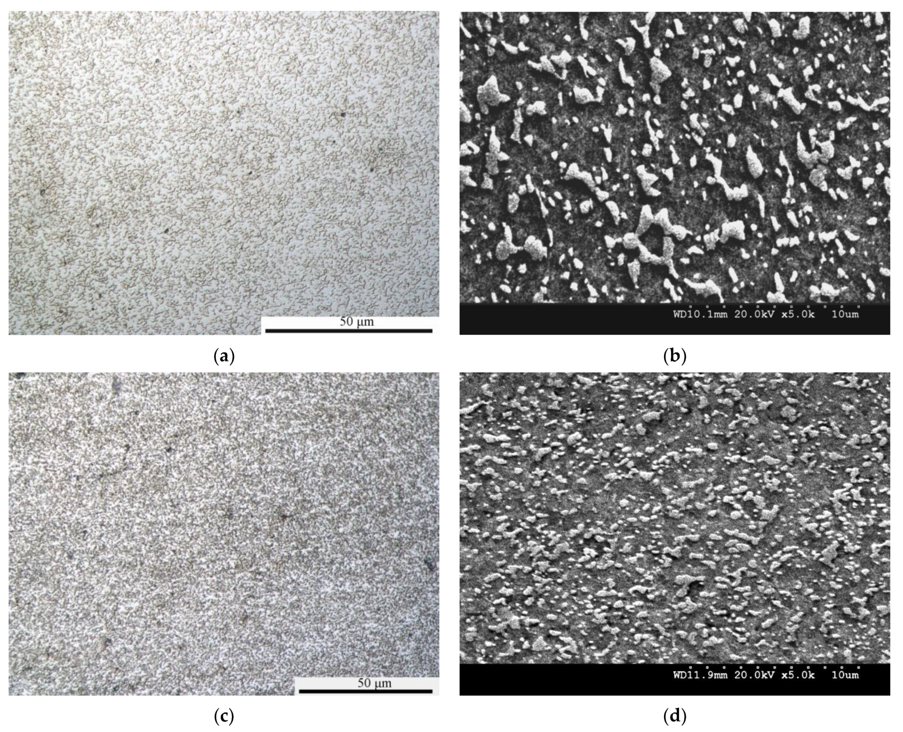
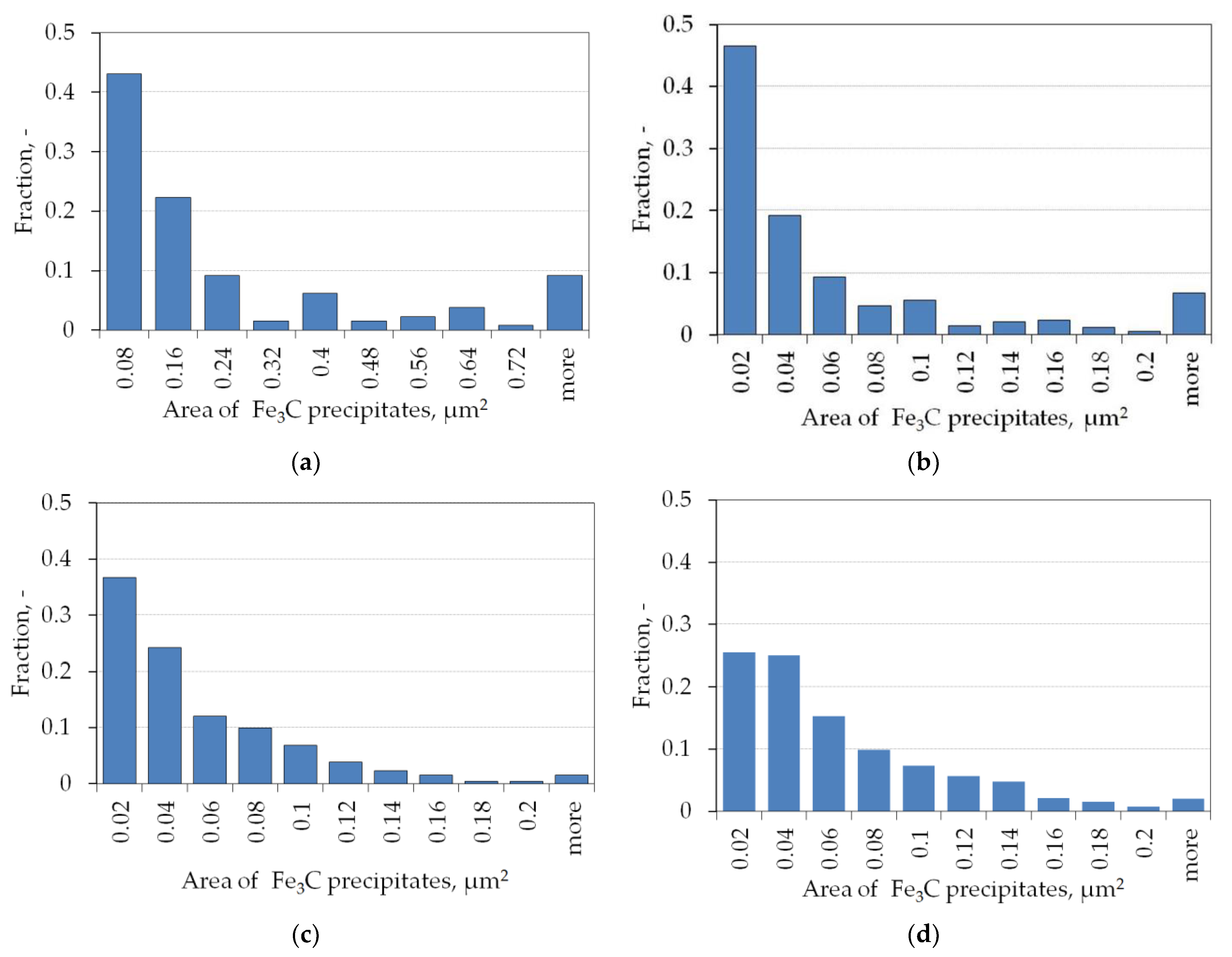
3.2. Microstructure
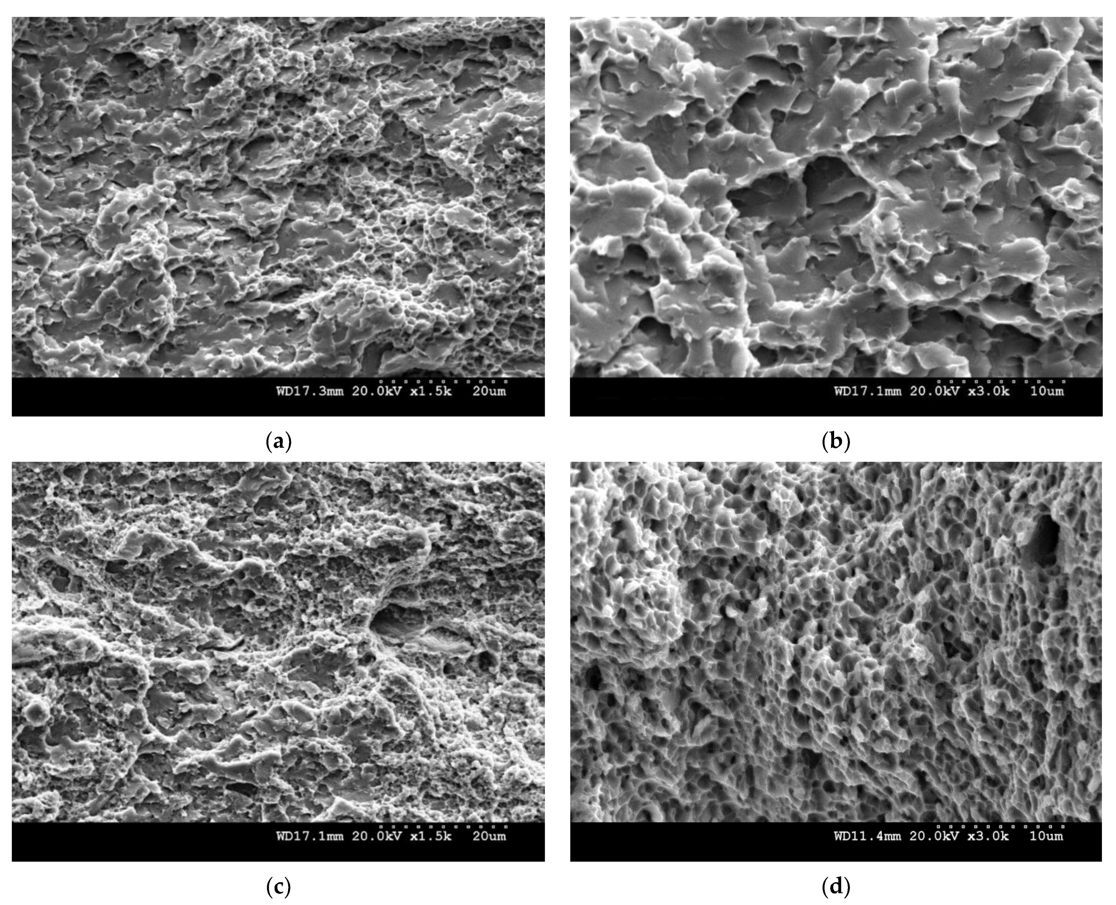
3.3. Fractography
3.4. Hardness
4. Discussion
5. Conclusions
Author Contributions
Funding
Institutional Review Board Statement
Informed Consent Statement
Data Availability Statement
Acknowledgments
Conflicts of Interest
References
- Lesuer, D.R.; Syn, C.K.; Goldberg, A.; Wadsworth, J.; Sherby, O.D. The case for ultrahigh carbon steel as structural materials. JOM 1993, 45, 40–46. [Google Scholar] [CrossRef]
- Verhoeven, J.D.; Gibson, E.D. The divorced eutectoid transformation in steel. Metall. Mater. Trans. A 1998, 29, 1181–1189. [Google Scholar] [CrossRef]
- Storojeva, L.; Ponge, D.; Kaspar, R.; Raabe, D. Development of microstructure and texture of medium carbon steel during heavy warm deformation. Acta Mater. 2004, 52, 2209–2220. [Google Scholar] [CrossRef] [Green Version]
- Furuhara, T.; Poorganji, B. Formation of ultrafine grained ferrite + cementite duplex structure by warm deformation. In Advanced Steels; Weng, Y., Dong, H., Gan, Y., Eds.; Springer: Berlin/Heidelberg, Germany, 2011; pp. 495–500. [Google Scholar] [CrossRef]
- Wu, T.; Gao, Y.; Wang, M.; Li, X.; Zhao, Y.; Zou, Q. Influence of initial microstructure on warm deformation processability and microstructure of an ultrahigh carbon steel. J. Iron Steel Res. Int. 2014, 21, 52–59. [Google Scholar] [CrossRef]
- Furuhara, T.; Yamaguchi, T.; Furimoto, S.; Maki, T. Formation of (ferrite + cementite) microduplex structure by warm deformation in high carbon steels. Mater. Sci. Forum 2007, 539–543, 155–160. [Google Scholar] [CrossRef]
- Zhao, X.; Jing, T.F. Warm deformation behavior of medium carbon steel with different initial microstructures. Mater. Sci. Eng. A 2012, 543, 267–270. [Google Scholar] [CrossRef]
- Arruabarrena, J.; Lopez, B.; Rodriguez-Ibabe, J.M. Influence of prior warm deformation on cementite spheroidization process in a low-alloy medium carbon steel. Metall. Mater. Trans. A 2014, 45, 1470–1484. [Google Scholar] [CrossRef]
- Chen, W.; Li, L.; Yang, W.; Sun, Z.; He, J. Microstructure evolution of hypereutectoid steels during warm deformation. Acta Metall. Sin. 2009, 45, 151–155. [Google Scholar]
- Sherby, O.D.; Oyama, T.; Kum, D.W.; Walser, B.; Wadsworth, J. Ultrahigh carbon steel. JOM 1985, 37, 50–56. [Google Scholar] [CrossRef]
- Maki, T.; Furuhara, T. Microstructure and mechanical properties of ultra-fine (ferrite + cementite) duplex structure in high carbon steel. Mater. Sci. Forum 2003, 426–432, 19–26. [Google Scholar] [CrossRef]
- Tsuzaki, K.; Sato, E.; Furimoto, S.; Furuhara, T.; Maki, T. Formation of an (α + θ) microduplex structure without thermomechanical processing in superplastic ultrahigh carbon steels. Scr. Mater. 1999, 40, 675–681. [Google Scholar] [CrossRef]
- Syn, C.K.; Lesuer, D.R.; Sherby, O.D. Influence of microstructure on tensile properties of spheroidized ultrahigh-carbon (1.8 pct C) steel. Metall. Mater. Trans. A 1994, 25, 1481–1493. [Google Scholar] [CrossRef]
- Abosbaia, A.A.S. Design and Processing Low Alloy High Carbon Steel by Powder Metallurgy. Ph.D. Thesis, University of Bradford, Bradford, UK, 2010. [Google Scholar]
- Mitchell, S.C.; Youseffi, M.; Abosbaia, A.A.S.; Ernest, J. Processing and heat treatment of high carbon liquid phase sintering steels. Powder Metall. Prog. 2008, 8, 91–100. [Google Scholar]
- Abosbaia, A.A.S.; Mitchell, S.C.; Youseffi, M.; Wronski, A.S. Liquid phase sintering, heat treatment and properties of ultrahigh carbon steels. Powder Metall. 2011, 54, 592–598. [Google Scholar] [CrossRef]
- Fan, Y.; Cao, J.; Wang, W.; Liu, Y. Microstructure and mechanical properties of a 1.6C (pct) ultra-fine grained ultra-high carbon steel. Mater. Sci. Forum 2011, 682, 131–137. [Google Scholar] [CrossRef]
- Sherby, O.D.; Walser, B.; Young, C.M.; Cady, E.M. Superplastic UHCSs. Scripta Met. 1975, 9, 569–574. [Google Scholar] [CrossRef]
- Zhang, H.; Bai, B.; Raabe, D. Superplastic martensitic Mn–Si–Cr–C steel with 900% elongation. Acta Mater. 2011, 59, 5787–5802. [Google Scholar] [CrossRef]
- Szczepanik, S.; Sińczak, J. Determination of the conditions for heavy deformations of sintered steel containing 1.4%C. Metall. Foundry Eng. 1994, 20, 441–448. [Google Scholar]
- Nikiel, P.; Szczepanik, S.; Skrzypek, S.J.; Rogal, Ł. The effect of thermo-mechanical treatment on structure of ultrahigh carbon PM steel. J. Mater. Eng. Perform. 2017, 26, 1562–1568. [Google Scholar] [CrossRef]
- Szczepanik, S.; Mitchell, S.C.; Abosobia, A.A.S.; Wroński, A.S. Warm forging of spheroidised ultra high carbon steel. Powder Metall. Prog. 2010, 101, 59–65. [Google Scholar]
- Szczepanik, S.; Nikiel, P.; Mitchell, S.C.; Kawalla, R. Microstructure evolution in warm forged sintered ultrahigh carbon steel. Arch. Civ. Mech. Eng. 2015, 15, 301–307. [Google Scholar] [CrossRef]
- Szczepanik, S.; Mitchell, S.C.; Wronski, A.S.; Abosbaia, A.A.S.; Nikiel, P.; Krawiarz, J. Microstructure evolution in fully dense warm forged sintered ultrahigh carbon steel. Powder Metall. Prog. 2011, 11, 78–84. [Google Scholar]
- Kawasaki, M.; Langdon, T.G. Developing superplasticity in ultrafne-grained metals. Acta Phys. Pol. A 2015, 128, 470–478. [Google Scholar] [CrossRef]
- Najafizadeh, A.; Jonas, J.J. Predicting the critical stress for initiation of dynamic recrystallization. ISIJ Int. 2006, 46, 1679–1684. [Google Scholar] [CrossRef] [Green Version]
- Polliak, E.I.; Jonas, J.J. A one-parameter approach to determining the critical conditions for the initiation of dynamic recrystallization. Acta Mater. 1996, 44, 127–136. [Google Scholar] [CrossRef]
- Moon, J.R. Hardness and the properties of PM materials measured in tension. Powder Metall. Prog. 2015, 15, 234–244. [Google Scholar]


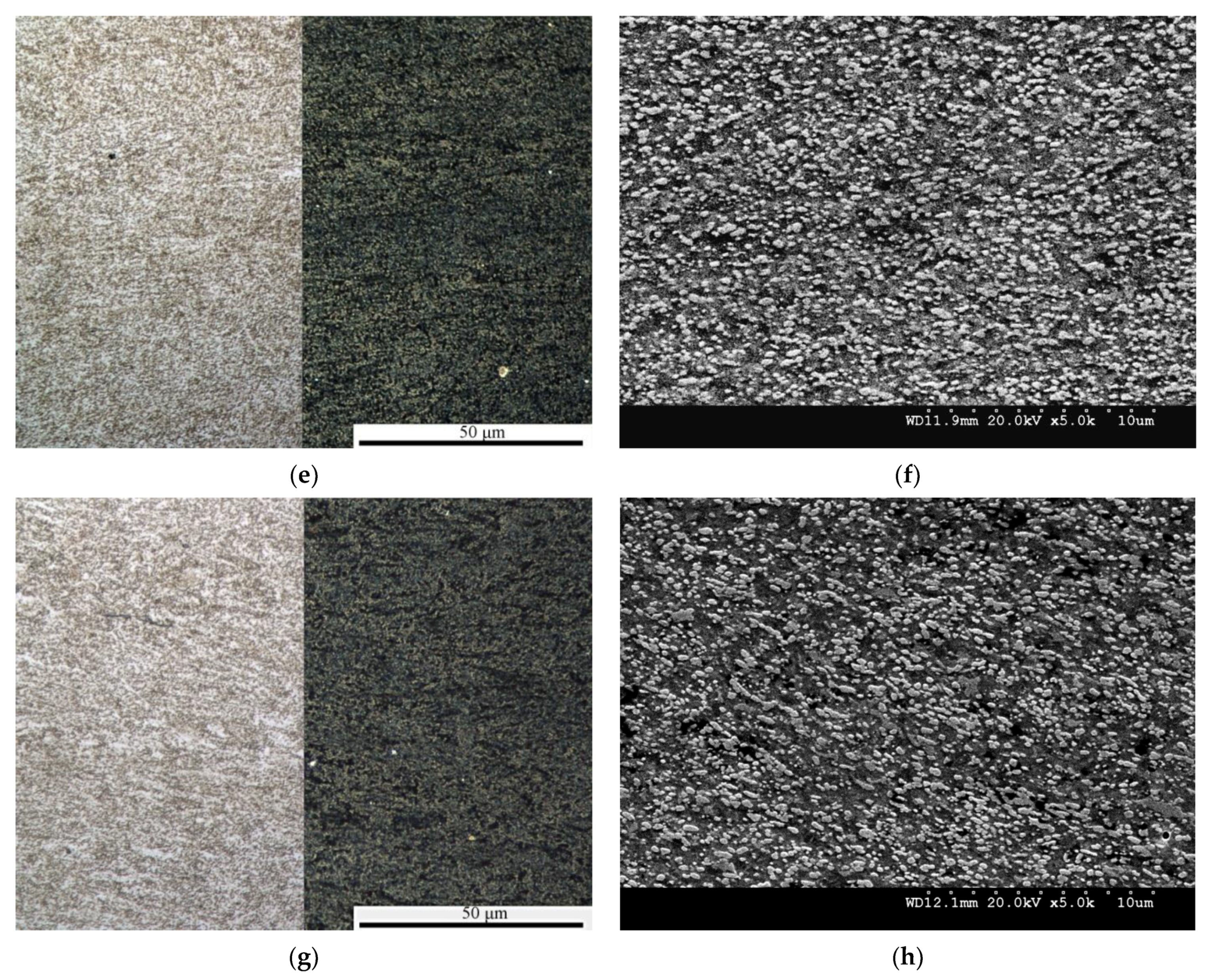
| No. | Strain Rate, s−1 | Number of Analyzed Particles, - | Average Surface Area A, μm2 | Average Feret Diameter D, μm | 1 Shape Factor (Circularity) f, - |
|---|---|---|---|---|---|
| 1 | 0.001 | 130 | 0.27 | 0.71 | 0.69 |
| 2 | 0.01 | 344 | 0.08 | 0.36 | 0.73 |
| 3 | 0.1 | 626 | 0.05 | 0.33 | 0.77 |
| 4 | 1 | 655 | 0.05 | 0.35 | 0.77 |
| No. | Strain Rate, s−1 | Hardness HV10 |
|---|---|---|
| 1 | 0.001 | 295 ± 18.8 |
| 2 | 0.01 | 339 ± 13.8 |
| 3 | 0.1 | 359 ± 6.9 |
| 4 | 1 | 362 ± 2.9 |
| Bähr at 775 °C—Quenched | Gleeble Quenched and Spheroidised at 750 °C [22] | |||||
|---|---|---|---|---|---|---|
| εp, - | εc, - | σp, MPa | σc, MPa | εp, - | σp, MPa | |
| 0.001 | 0.16 | 0.04 | 110 | 97 | 0.05 | 150 |
| 0.01 | 0.28 | - | 243 | - | 0.16 | 250 |
| 0.1 | 0.28 | 0.09 | 304 | 270 | 0.2 | 330 |
| 1 | 0.47 | 0.24 | 542 | 458 | 0.22 | 460 |
| State | Processing/ Testing | Microstructure | Ferrite Grain Size µm | Yield Strength MPa | Hardness HV10 | Reference |
|---|---|---|---|---|---|---|
| Sintered | 1300 °C, cooled slowly to room temperature | fine pearlite and grain boundary Fe3C | 400 * | 196–325 | [15,16] | |
| Quenched | austenitized at 970 °C, isothermally quenched, Bähr tested at 775 °C | ferrite matrix and dispersed spheroidal carbides | 1–3 | 715–1030 * | 295–362 | Current report |
| Spheroidized at 750 °C | room temperature deformation | ferrite matrix and dispersed spheroidal carbides | 30 | 350–410 | 150–230 | [15,24] |
| Gleeble tested at 700 °C | fine-grained ferrite and homogeneously distributed carbides | 6–7 | 769 | 310 | [22] | |
| twice forged: 700 °C and 750 °C | fine-grained ferrite and homogeneously distributed carbides | 6–7 | 769–744 | - | [22] |
| State | Grain Size, L, µm | Inter-Carbide Spacing, Ds*, µm | 310 Ds* −1/2, MPa | 460 L−1/2, MPa | Calculated Yield Strength, MPa | Yield Strength, MPa |
|---|---|---|---|---|---|---|
| Quenched, spheroidised during Bӓhr testing | 1–3 | 0.628–0.298 | 378–549 | 265–460 | 643–1009 | 715–1030 * |
| Spheroidized at 750 °C | 30 | 0.78 | 339 | 83 | 422 | 350–410 |
| Spheroidized and forged | 7 | 0.826–0.59 | 403–520 | 187 | 667 | 769–744 |
Publisher’s Note: MDPI stays neutral with regard to jurisdictional claims in published maps and institutional affiliations. |
© 2021 by the authors. Licensee MDPI, Basel, Switzerland. This article is an open access article distributed under the terms and conditions of the Creative Commons Attribution (CC BY) license (http://creativecommons.org/licenses/by/4.0/).
Share and Cite
Nikiel, P.; Szczepanik, S.; Korpała, G. Accelerated Spheroidization of Cementite in Sintered Ultrahigh Carbon Steel by Warm Deformation. Metals 2021, 11, 328. https://doi.org/10.3390/met11020328
Nikiel P, Szczepanik S, Korpała G. Accelerated Spheroidization of Cementite in Sintered Ultrahigh Carbon Steel by Warm Deformation. Metals. 2021; 11(2):328. https://doi.org/10.3390/met11020328
Chicago/Turabian StyleNikiel, Piotr, Stefan Szczepanik, and Grzegorz Korpała. 2021. "Accelerated Spheroidization of Cementite in Sintered Ultrahigh Carbon Steel by Warm Deformation" Metals 11, no. 2: 328. https://doi.org/10.3390/met11020328