Article

Dissimilar Welding of Low Alloy Steels Welded Joints: Effect of Run-Off and Run-On Plates

1
Department of Civil Engineering, Chosun University, Gwangju 61452, Korea
2
Department of Naval Architecture and Ocean Engineering, Chosun University, Gwangju 61452, Korea
*
Author to whom correspondence should be addressed.
Metals 2021, 11(4), 642; https://doi.org/10.3390/met11040642
Submission received: 25 March 2021 / Revised: 9 April 2021 / Accepted: 12 April 2021 / Published: 14 April 2021
(This article belongs to the Special Issue Welding and Fatigue of Railway Metallic Materials)

Abstract

:
The steel run-off plates attached at the start and end of a weld usually have the same material, shape, and groove as the base metal according to the rules for designing and constructing ship steel structures. However, rather than using the same grade of base steel, readily available steel is often used for these plates to increase material utilization. When using dissimilar grade steel as a run-off plate, the physical properties of the base metal may be diluted if the weld joint of the base plate is penetrated, thereby lowering the physical property value of the joint. If the physical properties of the welded part of the real structure are lowered because of the dilution of the properties of the dissimilar grade steel material, the safety of the entire structure can be affected. Therefore, in this study, analyses of the metal microstructure, hardness, impact, and chemical composition were performed on surfaces where the run-off plate was removed after welding to examine the effect of dissimilar run-off plate. The results of this study reveal that the properties of the run-off plate were not diluted toward the base metal and the Charpy impact value at the weld end was up to 48% greater than the impact value at the start of the weld at a temperature of −40 °C.

1. Introduction

Run-off plates are temporarily attached to steel structures for a variety of purposes. For example, they are attached to the weld-line extension of the base material during welding operations (e.g., butt welding, head welding of flanges and webs, and edge welding) [1]. Generally, the run-off plate has the same material, shape, and groove properties as the base metal. Run-off plates are used to stably generate arcs at the beginning and end of the welding process. Without a run-off plate, defects including blowholes and craters are more likely [1]. The run-off plates help prevent defects from propagating to the base material. The welding is completed by extending the end of the weld by approximately 100 mm from the joint on the run-off plate, and the length of the extended weld becomes indispensable as the thickness of the steel plate increases. After welding is completed, the run-off plate is removed using gas cutting, and the cutting surface is treated by grinding. The run-off plate is generally manufactured from a weldable material, such as that of the base metal itself.
Another purpose of the run-off plate is to prevent end cracks during welding when the welding speed and heat input are high. Run-off plates are used to prevent gaps in the grooves from being opened or closed via thermomechanical deformation during rotary friction welding in one-sided butt welding [2,3], which depends on the amount of heat transferred and the welding speed. In particular, grooves tend to widen at high welding temperatures and speeds. This phenomenon largely occurs at the end of the weld, causing cracks to appear in the run-off plate attached to the end section. Moreover, this crack propagates to the base material after the run-off plate is removed, resulting in cold cracking. To prevent cold cracking [4,5,6], proper end fittings and special run-off plates must be installed. Therefore, securing the properties of the run-off plate is very important to ensure the safety of the structure.
A run-off plate attached at the start/end of welding is a steel plate that usually has the same material, shape, and groove as the base metal according to the rules for de-signing and constructing steel structures. However, rather than using the same grade of base steel as the run-off plate, readily available steel is often used to increase the material utilization rate [7,8,9]. When using dissimilar grade steel as a run-off plate, the problem arises that the physical properties of the run-off plate may be diluted if the weld portion of the base material is penetrated, thereby deteriorating the physical properties of the base weld portion. Accidents caused by weak structural integrity result in inflation in safety and cost concerns owing to the increasing design requirements [10]. Nouri [11] and Tomkow [12,13] conducted a study on gas–metal arc welding and found that the faster the welding wire-feed rate, the greater the dilution, bead height, and width. The welding speed, in contrast, was reduced. Rogalski [14,15,16,17] et al. evaluated the integrity of the weld strength of dissimilar welds through macro-and microscopic examination and hardness measurements in TIG and laser welding. In heterogeneous laser welding of AISI 430F (X12CrMoS17) martensitic stainless steel and AISI 304 (X5CrNi18-10) austenitic stainless steel, a large number of pores were detected, and martensite increased compared to the base material in the heat affected zone, and a mixture was detected. The hardness range in the weld metal, caused by chemical inhomogeneity, was 184-416 HV0.3. Om and Pandey [18] and Gunaraja and Murugan [19,20] investigated the effects of submerged arc welding (SAW) polarity and weld parameters on the size and dilution of the heat-affected zone (HAZ). The investigation revealed that the width and area of the HAZ increased linearly with the heat input, irrespective of the polarity. To date, studies have been conducted on run-off plates to prevent cracking at the welding end and on the dilution between the base metal and welding wire during welding. However, practical research has not been conducted on the transfer of the properties of the run-off plate to the base material when welding is performed from the run-off plate to the base material. This study aims to solve the problem of satisfying the rule that the material of the run-off plate and the material of the base material must be the same material at steel structure manufacturing sites.
In this study, the effects of the material properties of the run-off plate on one of the bases after the removal of the Run-off plates were investigated. For this purpose, the effects of the components of the run-off plate on the base plate were evaluated by comparing and analyzing the metal microstructure, hardness, Charpy impact, and chemical composition of the surface upon removal of the run-off plate.

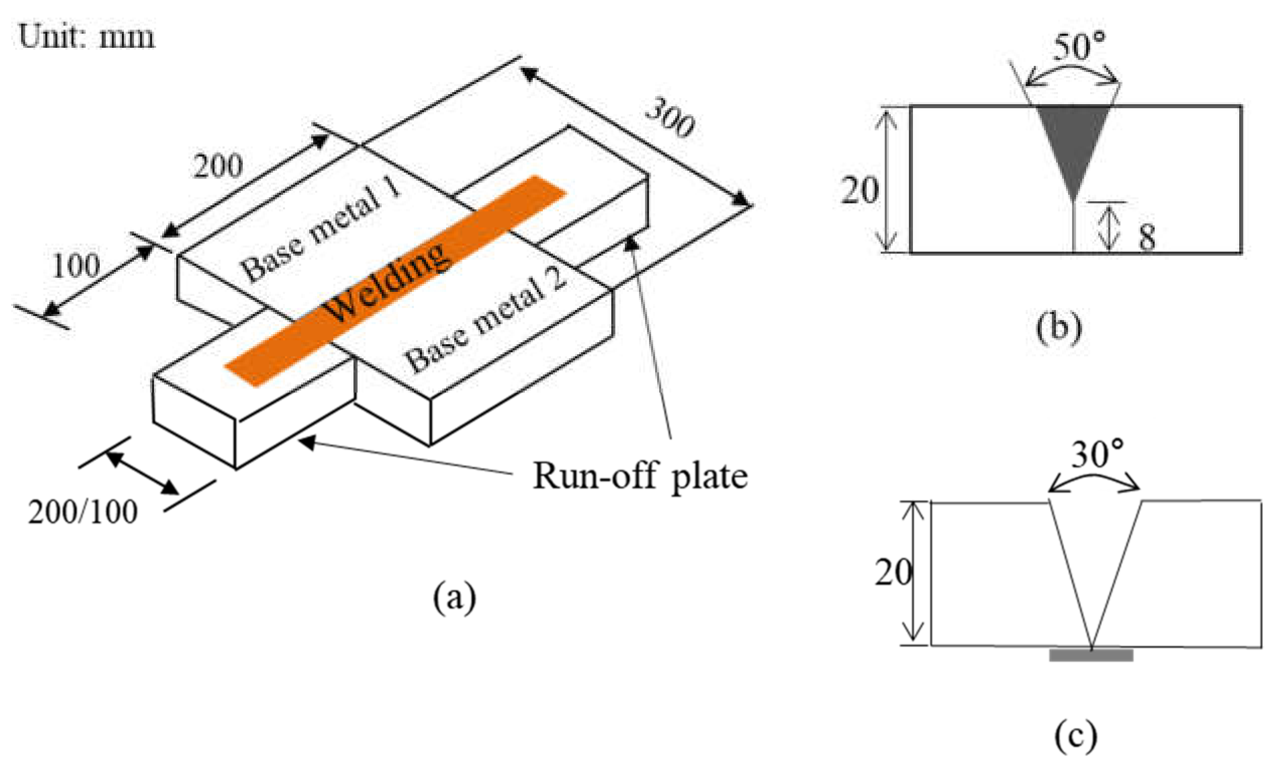
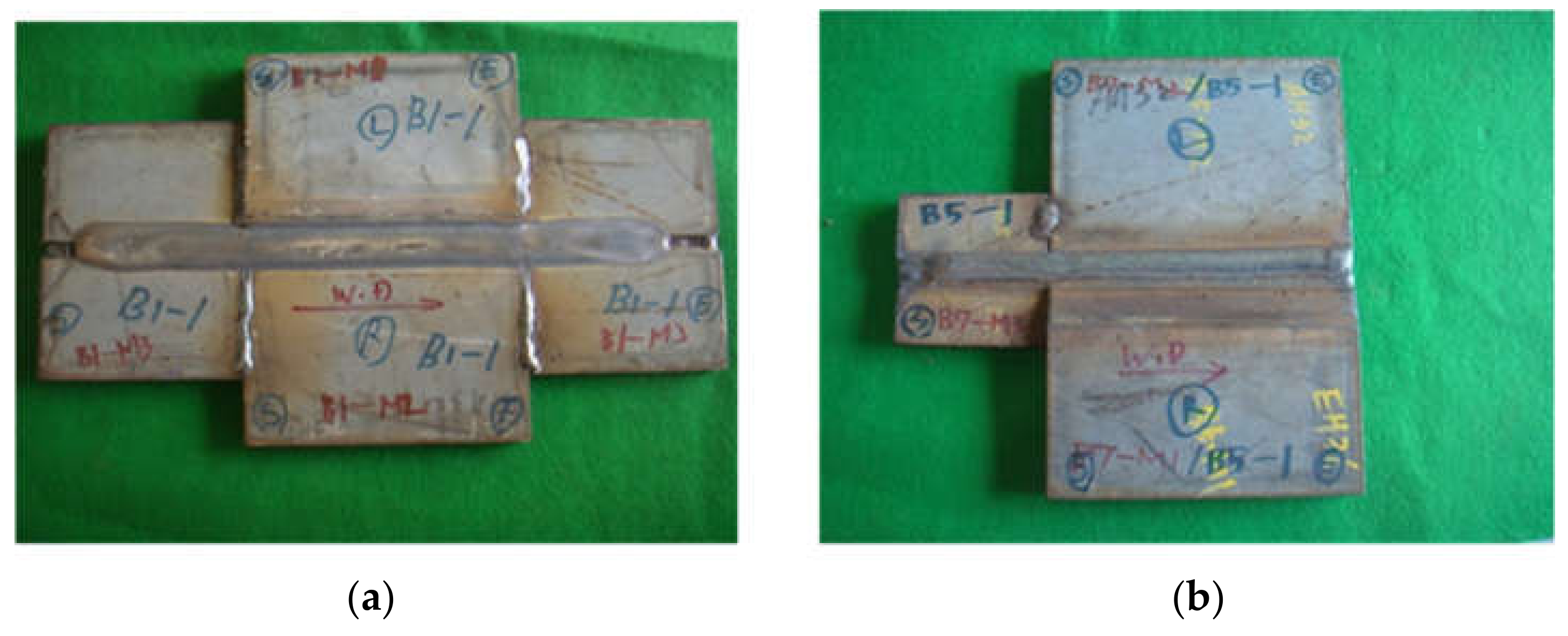
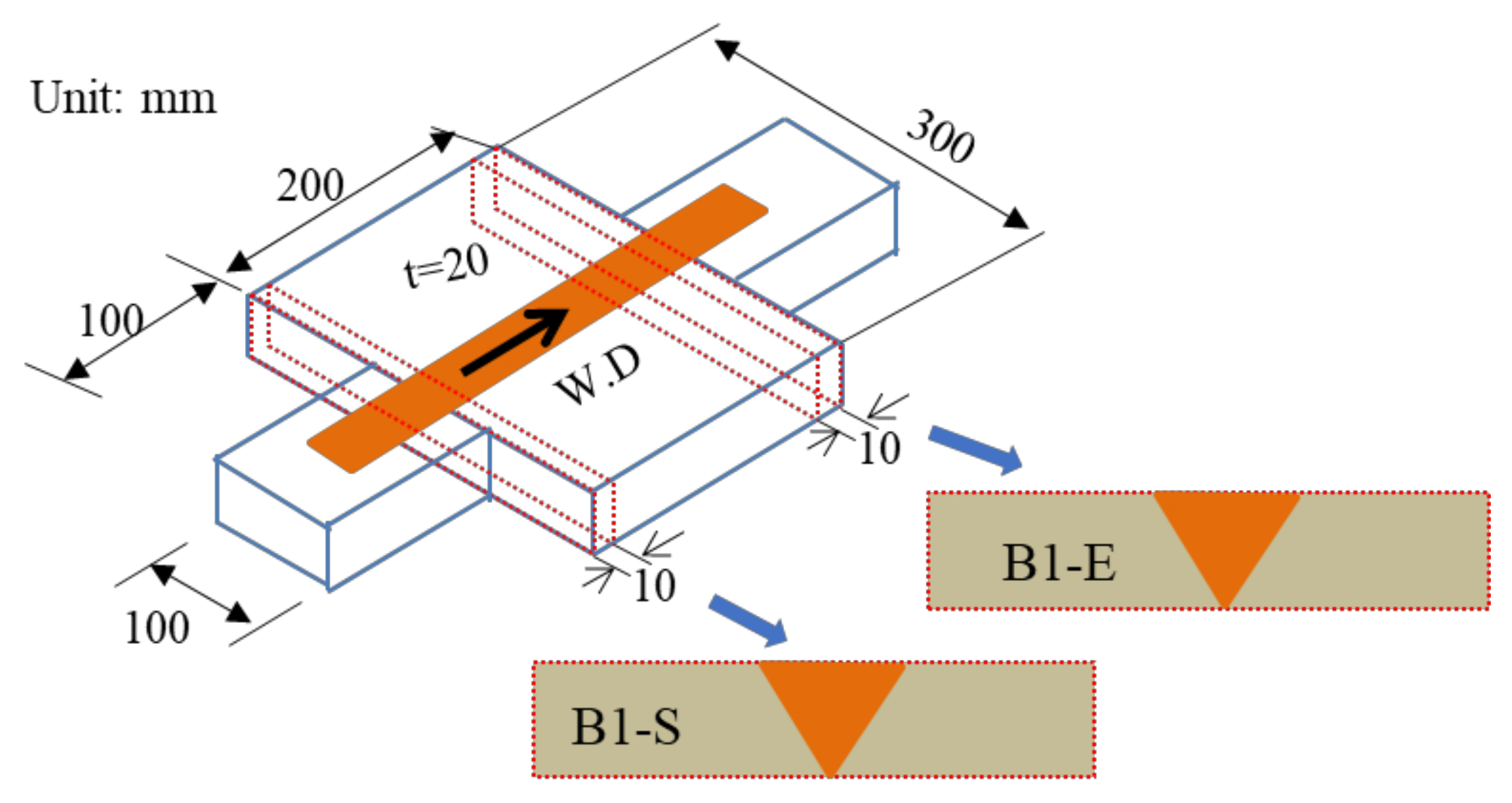
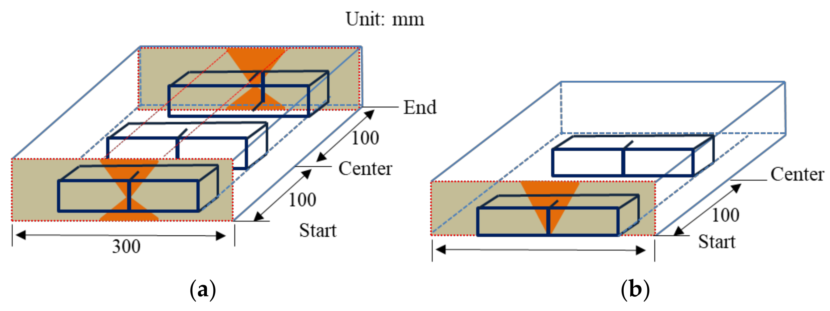
2. Materials and Test Methods

The material used in the experimental examination was AH36, DH36, EH36, a commercial, high-strength low-carbon steel that was fabricated by a thermo-mechanically controlled processing method (TMCP). Table 1 and Table 2 present the chemical composition and the mechanical properties of the base metal and welding consumables, respectively, based on the specification requirements. Figure 1 shows the shape of the butt-welded specimen. The weld length was 200 mm, the overall width was 300 mm, and the thickness was 20 mm. The run-off plate used here had dimensions of 100 mm × 100 mm × 20 mm (length × width × thickness). The welded joints were subjected to SAW with Y-grooves (Figure 1b), flux-core arc welding (FCAW), and multi-layer welding with V-grooves (Figure 1c). Figure 2 shows a photograph of the SAW and FCAW specimens. Table 3 shows the butt-welded test specimen steel and welding methods used for the test, and Table 4 lists the welding conditions. Test specimen preparation and testing were performed according to ASTM standard A1106/A1106M-17.
Figure 3 shows the location of the test specimen at the beginning and end of the butt weld. To investigate the effect of dilution of the base metal and run-off plate, the latter was removed, and the test specimens were made from the beginning and the end of the weld.
At the beginning of the weld, much attention was paid to the possibility of bringing molten material from the run-off plate into the base metal, which could affect the properties of the base metal. B1-S denotes the test specimen, where B denotes the butt, the number denotes the test piece, S denotes the welding start portion, and E denotes the welding termination portion.
Figure 4 shows the location of the impact-test specimens taken from the root of the weld. For SAW, the specimens were taken from the beginning, end, and center of the weld, and the FCAW welds were taken from the beginning and center. The test temperatures were −40 °C at the start and end of welding and 0, −20, and −40 °C at the center.

3. Results and Discussion

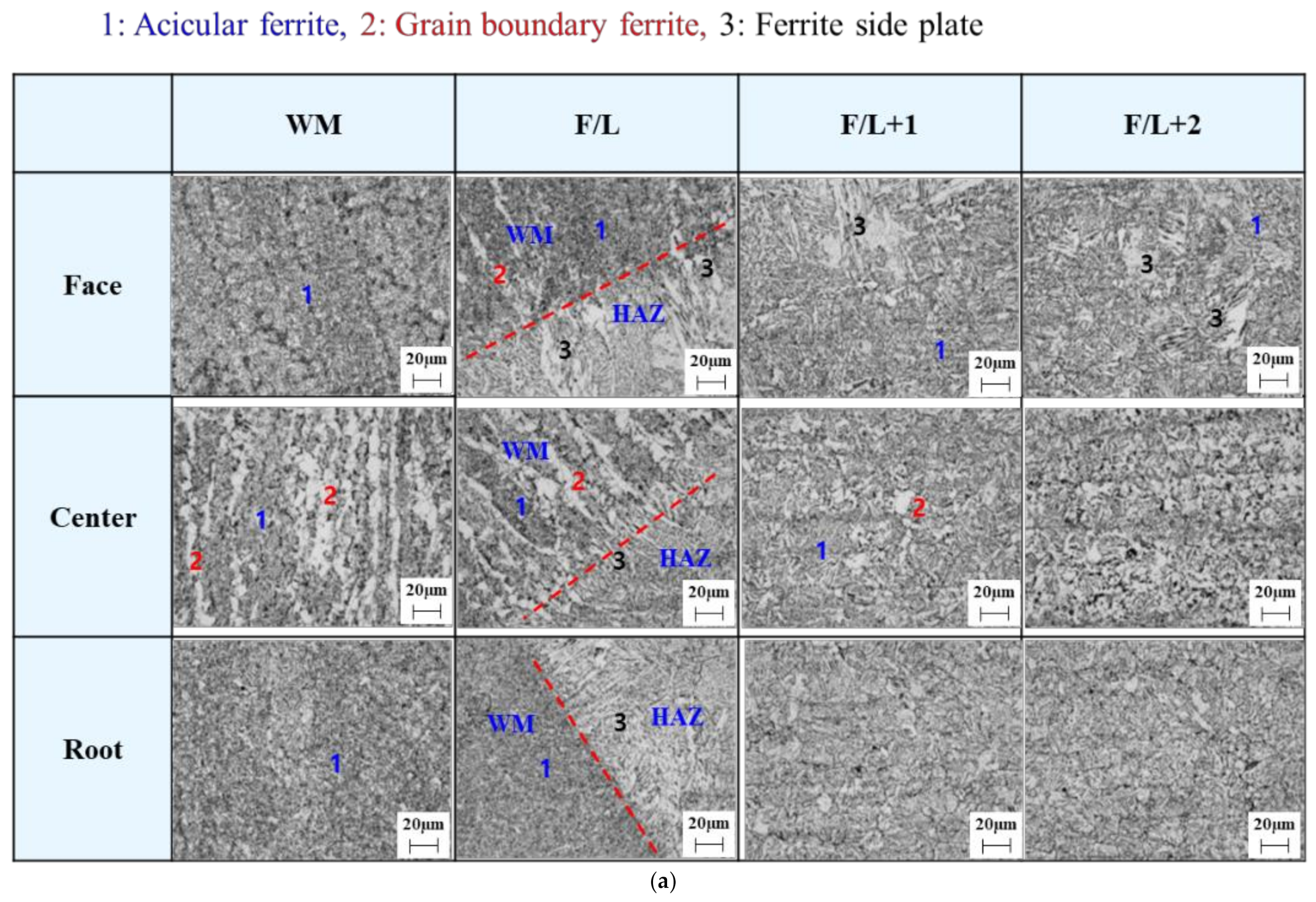
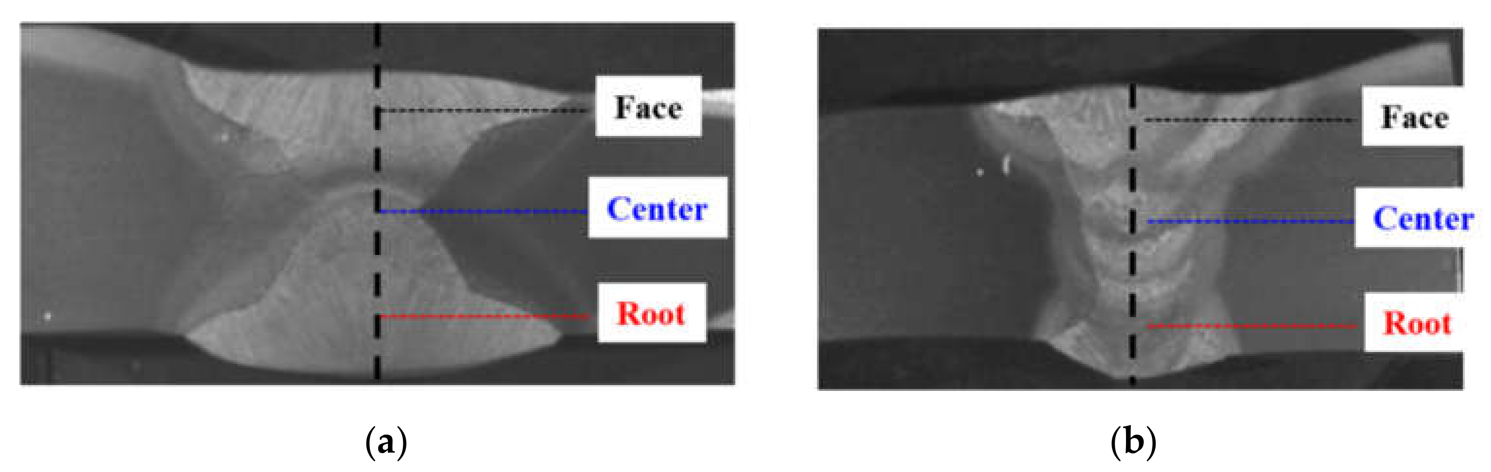
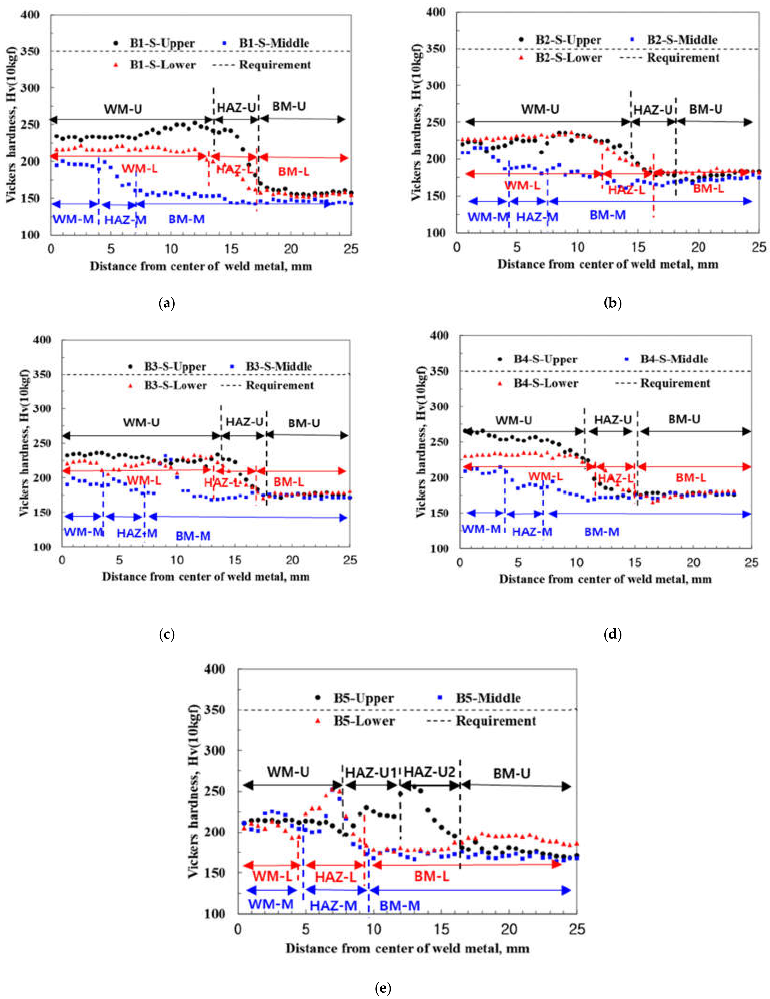
3.1. Microstructure and Hardness
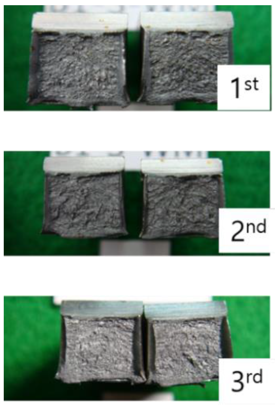
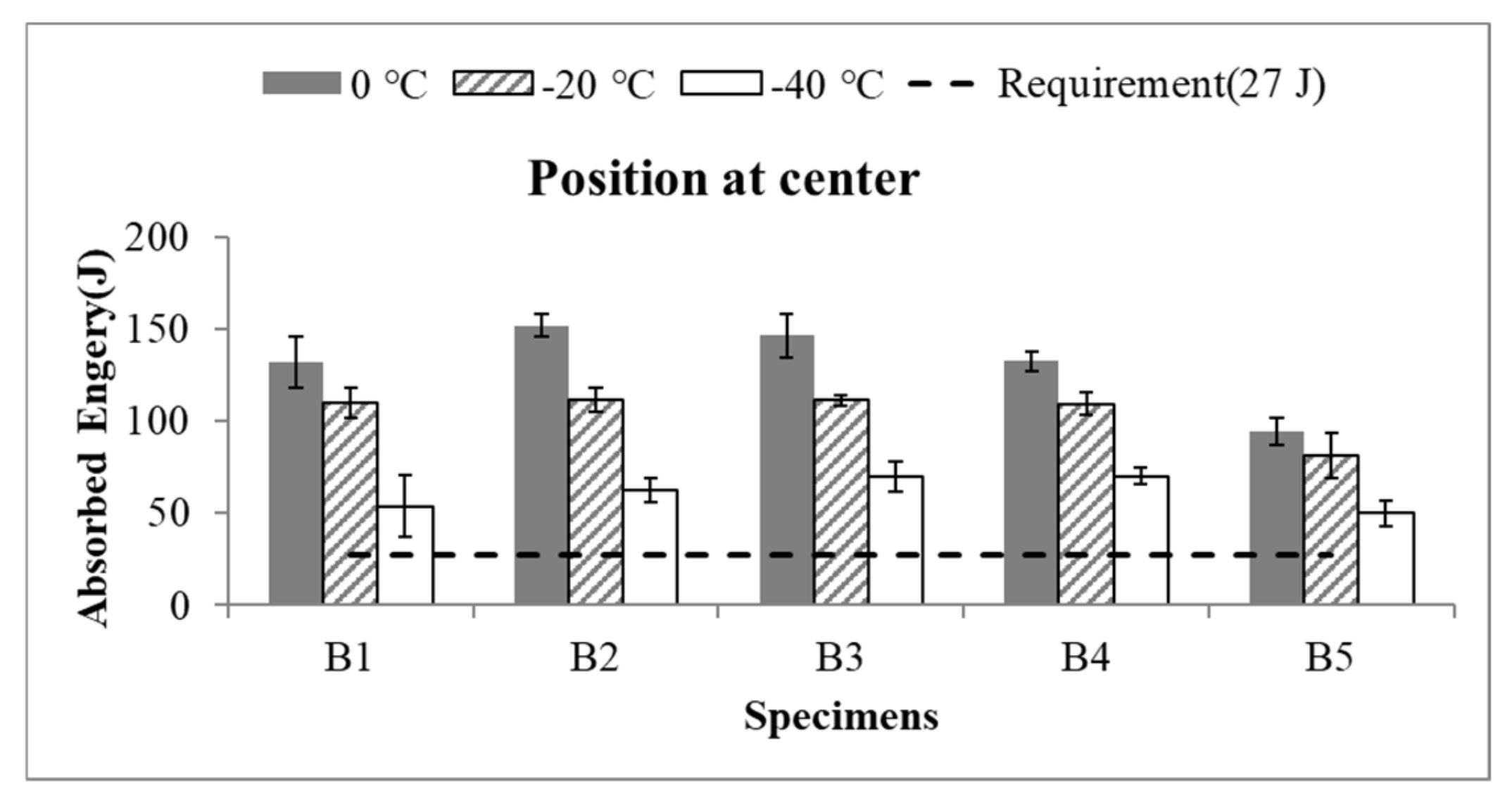
Mounting, polishing, and etching operations were required to inspect the metal microstructures of the base metal from where the run-off plates were removed. A resin and hardener were mixed and placed in a frame with a sample and subsequently hardened. The mounted specimens were then polished using rough and soft sandpapers consecutively. The surface of the test specimen was corroded using nitric acid and alcohol. The welds were cut, and the metal microstructure was observed under a 200× optical microscope (LEICA, model; Leica DM6000M, Micro Support Co., Ltd, Shizuoka, Japan). Figure 5 shows the metal microstructure at the face, center, and root of the cross-section after the removal of the run-off plate at the beginning and end of the weld about B1 and B5 on behalf of the specimens. The metal microstructures of the weld metal (WM), fusion line (F/L), fusion line and at 1 mm from the fusion line to width direction (F/L + 1), and fusion line and at 2 mm from the fusion line to width direction (F/L + 2) are also shown at their respective positions.
It can be seen that the microstructure of the deposited metal consists of grain-boundary ferrite (whitish) and acicular ferrite (black). A ferrite side plate (FSP) was developed in lath form along the grain-boundary ferrite. The mechanical properties of low-carbon welds are affected by the shape of the ferrite produced through the transformation during cooling, and the strength and toughness of the welds are related to the acicular ferrite fraction. The microstructure and fusion line are indicated by numbers and dotted lines in Figure 5. In the welded metal part of the SAW welding part, it can be seen that part of the reheating part of the face part, which is the first welding part, appeared by the second pass welding. To improve the toughness and strength, the grain-boundary ferrite and FSP transformation must be minimized, and needle ferrite should be produced in a larger fraction. It is evident from the micrographs that the microstructures of the test specimens were not significantly different.
The hardness values measured in the direction of the width from the center of the weld for the face, center, and root of the thickness are shown in Figure 6 (INDENTEC, model; ZHμ-A, Zwick Roell, Ulm, Germany). The measurement positions of the upper and lower surfaces were within 2 mm of the surface. Figure 7 shows the hardness values at the weld start and finish after the removal of the run-off plate. Adams reported that the cooling rate of a weld depends on the thickness and shape of the weld, welding conditions, temperature of the base metal, and preheat [21]. The weld metal and the HAZ of the SAW joints possess superior hardness to the base material, indicating the absence of a softening zone. Meanwhile, the hardness in HAZ of the FCAW is higher than that of the weld metal and base metal. This is because the SAW has a larger heat input than the FCAW, and its cooling rate is slow. Although the hardness value of the welded metal and the HAZ part is larger than that of the base metal, it is still less than 350 Hv10, which is the maximum value suggested by the American Bureau of Shipping (ABS) [22]. Therefore, it can be concluded that there was no change in the hardness value with respect to the run-off material.

3.2. Toughness

To confirm the toughness of the weld, Charpy impact tests were performed at −40 °C at the start and end of the weld (Tinius Olsen, model: IT 406). The impact-test pieces were taken from the center of the welding length and subjected to an impact test at the experimental temperatures of 0, −20, and −40 °C. The test results were averaged from three test pieces. Figure 8 shows a cross-sectional view of the specimen after the Charpy V-notch impact test.
Figure 9 shows the Charpy toughness at −40 °C at the start, center, and end of welding. Test pieces B1–B4 are SA welds, and B5 comprises test pieces taken from the FCAW. All of the impact energy values shown are above 27 J, which is the minimum value suggested by ABS [22]. According to the ABS standard, the welding part must satisfy the value of 27 J at −20 °C. However, in this study, it can be seen that the more severe condition satisfies 27 J at −40 °C. The Charpy impact value at the end of the weld was slightly larger than the start of the weld, but it was almost the same when considering the deviation of the experiment. In addition, both of the FCAW and SAW joints showed the satisfied rule requirement. According to the mill test report in Table 4, the SAW wire is a high-quality welding wire that can satisfy at least 27 J at −60 °C [23,24]. Figure 10 shows the toughness of the experiment at 0, −20, and −40 °C for the center of the weld length. In this case, however, all of the results indicated that the value was above the required minimum value (27 J). Therefore, it can be concluded that even if the steel type of the run-off plate differs from that of the base metal, the material properties of the run-off plate do not influence the physical properties of the welding joints of the base metal.

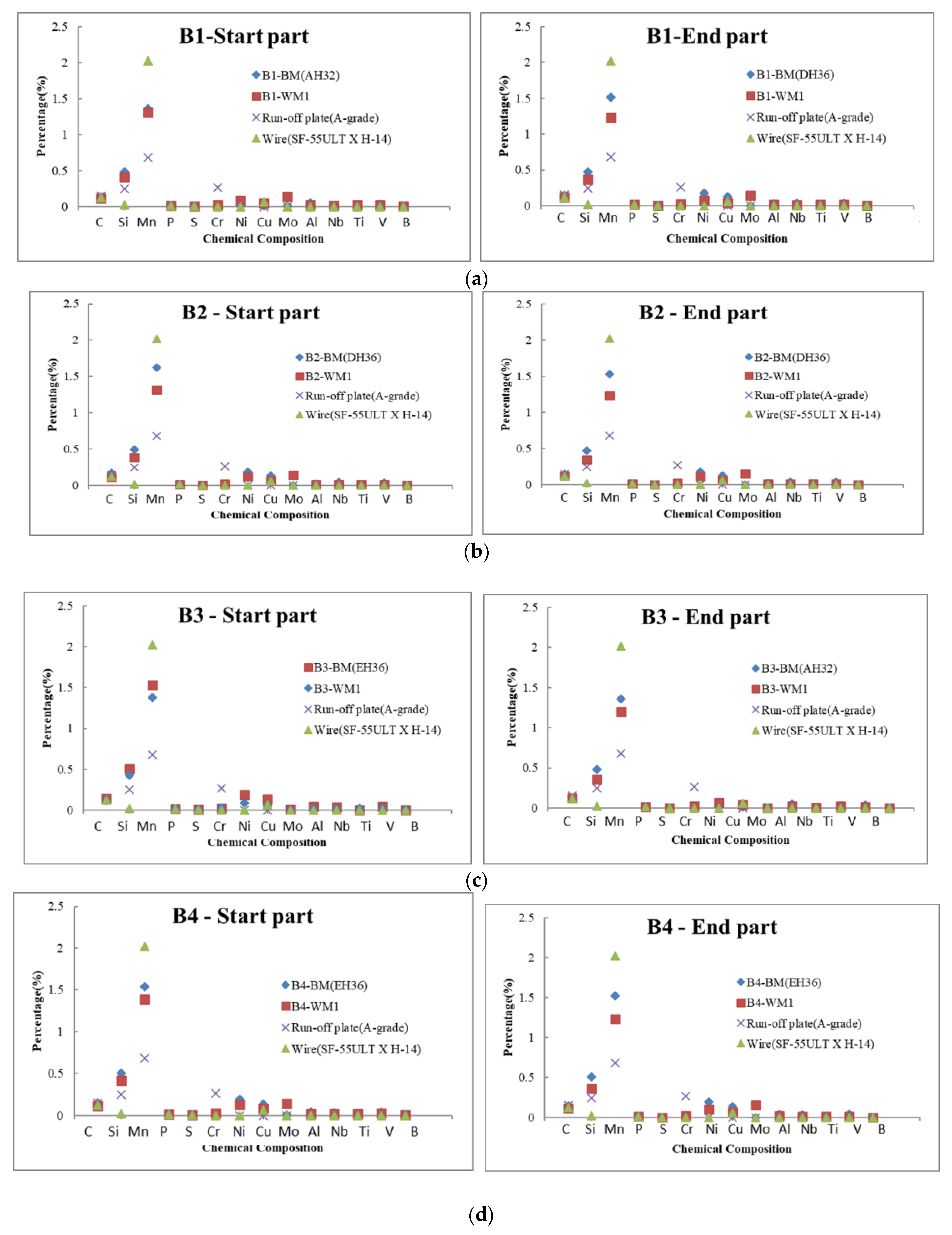
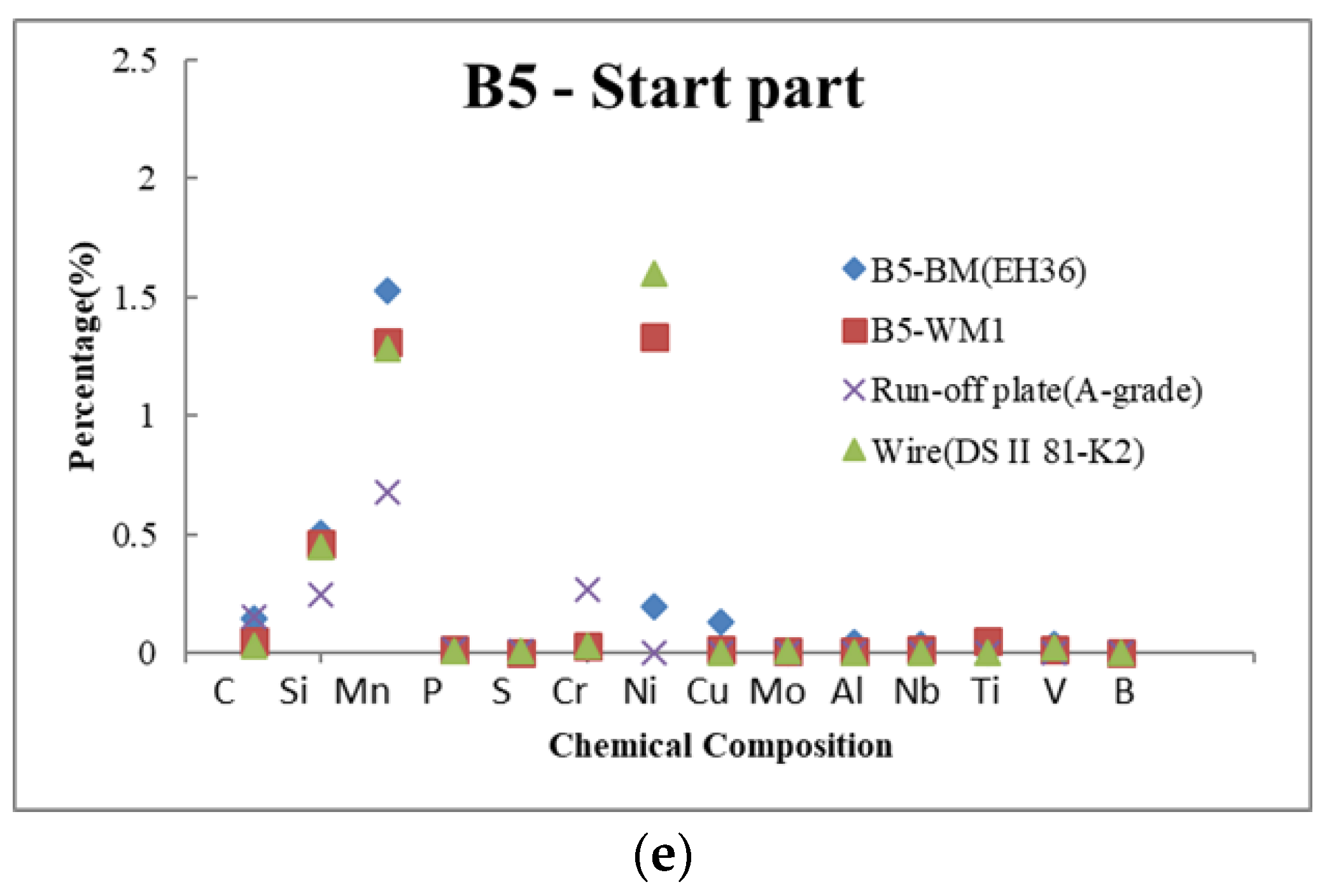
3.3. Component Analysis

A light-emission analysis and an emission spectrochemical analysis were performed to examine whether the metal component of the run-off plate was moved to the base material and diluted. The emission spectrochemical analysis (OXFORD, model: Foundry Master Xpert) is a method of quantitatively analyzing the spectral intensity of light emitted from a sample and determining the type or amount of the component element of the sample, based on the emission spectrum of the standard sample irradiated previously. Figure 11 shows the positions of the component analysis on the surface from which the run-off plate was removed. The measurement positions were located on the upper and lower welds (WM1 and WM2) and the two base metals (BM1 and BM2). In the graph, the components of the weld and base metals at the start/end of the weld are shown for comparison and analyzed.
Figure 12 shows a comparison of the welding metal component (WM1), base metal component (BM), run-off plate component (run-off plate), and welding wire component (wire) for the five test specimens. The B1–4 were fabricated via SAW. WM and BM are the measured values, and “run-off plate” and “wire” are the values of the mill test report. It is the Mn chemical content that differs significantly from the run-off plate and other metals in SAW. The Mn content of the run-off plate was ~0.7%, and approximately 1.2–2.0% in the weld wire and the measured base material. It can be seen that the chemical content of Mn between the run-off plate and the measured welding wire differs by approximately a factor of two. This indicates that the components of the run-off plate are not diluted by being transferred to the weld portion of the base material. By contrast, test piece B5 was fabricated via FCAW. Unlike SAW, the welding wire for FCAW contains ~1.5% of Ni. Furthermore, ~1.4% of Mn and 1.5% of Ni were detected in the wire, and 0.6% of Mn and 0.3% of Cr were detected in the run-off plate. Therefore, it can be confirmed that even with FCAW, the chemical composition of the run-off plate was not diluted by the weld of the base material. As in the result of this study and in the study of the effect of dilution of the welding part of the base material and lifting structure of different materials studied by Park [25] et al., the effect of the welding wire was the greatest on the welding part.

4. Conclusions

To investigate the effect of the material properties of the steel used in the run-off plate on the physical properties of the base metal after the run-off plates were removed, the microstructure, hardness test, Charpy impact test, and chemical compositions of the welding metal were compared and evaluated. In conclusion, the results of this analysis reveal that the properties of the run-off plate were not diluted toward the base metal, but only the properties of the welding wire were detected. A more detailed conclusion is as follows.
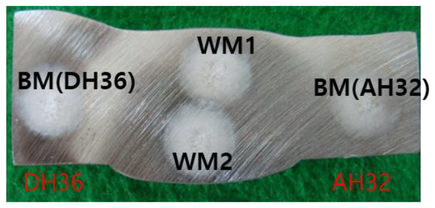
  • The metal microstructure of the cut surface was observed after the removal of the run-off plate. Only the metal microstructure of the welding wire could be observed in the weld metal, and changes in the metal microstructure caused by dissimilar welding between the base plate and run-off plate were not observed.
  • Although the hardness value of the welded part was larger than that of the other parts, it was still less than 350 Hv10.
  • The Charpy impact value at the end of the weld was slightly larger than the start of the weld, but it was almost the same when considering the deviation of the experiment. And it was confirmed that all of the impact results obtained were at a reference value of 27 J or higher.
  • All of the components measured at the welded part coincided with the wire component. This demonstrates that components of the run-off metal are not transferred to the base metal during welding.

Author Contributions

Conceptualization and investigation, G.A.; writing—original draft preparation and writing—review and editing, P.J. All authors have read and agreed to the published version of the manuscript.

Funding

This study was supported by a research fund from Chosun University, 2019.

Institutional Review Board Statement

Not applicable.

Informed Consent Statement

Not applicable.

Data Availability Statement

The data presented in this study are available in the article.

Conflicts of Interest

The authors declare no conflict of interest.

References

  1. Chen, W.-F.; Duan, L. Bridge Engineering Handbook: Construction and Maintenance; CRC Press: Boca Raton, FL, USA, 2014. [Google Scholar]
  2. Satoh, K.; Mukai, Y.; Toyoda, M. Welding Engineering; Tokyo Rikogakusha Publishing Japan: Tokyo, Japan, 1979. [Google Scholar]
  3. Masubuchi, K. Analysis of Welded Structures; Pergammon Press: Oxford, UK, 1980; pp. 268–269. [Google Scholar]
  4. Okuda, N.; Tanaka, K. Mechanism and Prevention of the End Crack in One Side Submerged Arc Welding (Report 1): The Effect of Welding Conditions and the Occurrence Mechanism. Trans. Jpn. Weld. Soc. 1983, 14, 63–64. [Google Scholar]
  5. Okuda, N.; Tanaka, K. Mechanism and Prevention of the End Crack in One Side Submerged Arc Welding (Report 2): Observation of Rotative Distortion and Its Prevention with the Tab Plate. Trans. Jpn. Weld. Soc. 1983, 14, 66. [Google Scholar]
  6. Asai, S. Trends of Automatic Welding System and In-Process Quality Control System. J. Jpn. Weld. Soc. 2012, 81, 34–44. [Google Scholar] [CrossRef] [Green Version]
  7. Coniglio, N.; Cross, C.E.; Michael, T.; Lammers, M. Defining a critical weld dilution to avoid solidification cracking in aluminum. Weld. J. 2008, 87, 237s–247s. [Google Scholar]
  8. Park, H.-C.; Lee, C.-H.; Chang, K.-H. Strengthening a damaged steel girder bridge by the replacement repair welding. KSCE J. Civ. Eng. 2012, 16, 1243–1249. [Google Scholar] [CrossRef]
  9. Shin, H.S.; Park, K.T.; Lee, C.H.; Chang, K.H.; Van Do, V.N. Low temperature impact toughness of structural steel welds with different welding processes. KSCE J. Civ. Eng. 2015, 19, 1431–1437. [Google Scholar] [CrossRef]
  10. Lee, J.-S.; Kim, M.-S. Strength Assessment of T-type Lifting Lugs Considering Deformation of Blocks. J. Ocean Eng. Technol. 2015, 29, 309–316. [Google Scholar] [CrossRef] [Green Version]
  11. Nouri, M.; Abdollah-Zadeh, A.; Malek, F. Effect of welding parameters on dilution and weld bead geometry in cladding. J. Mater. Sci. Technol. 2007, 23, 817. [Google Scholar]
  12. Tomków, J.; Fydrych, D.; Rogalski, G. Role of Bead Sequence in Underwater Welding. Materials 2019, 12, 3372. [Google Scholar] [CrossRef] [Green Version]
  13. Tomków, J.; Janeczek, A.; Rogalski, G.; Wolski, A. Underwater Local Cavity Welding of S460N Steel. Materials 2020, 13, 5535. [Google Scholar] [CrossRef]
  14. Rogalski, G.; Świerczyńska, A.; Landowski, M.; Fydrych, D. Mechanical and Microstructural Characterization of TIG Welded Dissimilar Joints between 304L Austenitic Stainless Steel and Incoloy 800HT Nickel Alloy. Metals 2020, 10, 559. [Google Scholar] [CrossRef]
  15. Pańcikiewicz, K.; Świerczyńska, A.; Hućko, P.; Tumidajewicz, M. Laser Dissimilar Welding of AISI 430F and AISI 304 Stainless Steels. Materials 2020, 13, 4540. [Google Scholar] [CrossRef]
  16. Landowski, M.; Świerczyńska, A.; Rogalski, G.; Fydrych, D. Autogenous Fiber Laser Welding of 316L Austenitic and 2304 Lean Duplex Stainless Steels. Materials 2020, 13, 2930. [Google Scholar] [CrossRef]
  17. Świerczyńska, A.; Landowski, M. Plasticity of Bead-on-Plate Welds Made with the Use of Stored Flux-Cored Wires for Offshore Applications. Materials 2020, 13, 3888. [Google Scholar] [CrossRef] [PubMed]
  18. Om, H.; Pandey, S. Effect of heat input on dilution and heat affected zone in submerged arc welding process. Sadhana 2013, 38, 1369–1391. [Google Scholar] [CrossRef] [Green Version]
  19. Gunaraj, V.; Murugan, N. Prediction and comparison of the area of the heat-affected zone for the bead-on-plate and bead-on-joint in submerged arc welding of pipes. J. Mater. Process. Technol. 1999, 95, 246–261. [Google Scholar] [CrossRef]
  20. Adams, C.M., Jr. Cooling Rates and Peak Temperatures in Fusion Welding. Weld. J. 1958, 37, 210–215. [Google Scholar]
  21. Sun, Y.L.; Obasi, G.; Hamelin, C.J.; Vasileiou, A.N.; Flint, T.E.; Balakrishnan, J.; Smith, M.C.; Francis, J.A. Effects of dilution on alloy content and microstructure in multi-pass steel welds. J. Mater. Process. Technol. 2018, 265, 71–86. [Google Scholar] [CrossRef]
  22. American Bureau of Shipping. PART 2 Materials and Welding. In Regulations of the Classification and Registry of Ships; American Bureau of Shipping: Houston, TX, USA, 2019. [Google Scholar]
  23. Bird, J. Improving the toughness of high strength GMA welds. Mar. Struct. 1993, 6, 461–474. [Google Scholar] [CrossRef]
  24. Choi, D.; Lee, H.; Cho, S.-K.; Kim, H.C.; Hyun, S.-K.; Shin, S.Y. Microstructure and Charpy Impact Properties of FCAW and SAW Heat Affected Zones of 100 mm Thick Steel Plate for Offshore Platforms. Met. Mater. Int. 2020, 26, 867–881. [Google Scholar] [CrossRef]
  25. Park, J.; An, G.; Lee, H. Influence on Properties of Base Metal after Elimination of Lifting-Lug Member in a Dissimilar Welding between Steel Base and Steel Lifting Lug. Int. J. Nav. Archit. Ocean Eng. 2019, 11, 858–864. [Google Scholar] [CrossRef]
Figure 1. Dimension and groove shape: (a) dimension and configuration; (b) submerged arc welding (SAW) (B1, B2, B3, and B4); and (c) flux-core arc welding (FCAW) (B5).
Metals 11 00642 g001
Figure 2. Welding specimens: (a) SAW (B1) and (b) FCAW (B5).
Metals 11 00642 g002
Figure 3. Location of specimen for hardness and dilution test.
Metals 11 00642 g003
Figure 4. Position of specimens in impact test: (a) SAW (B1–B4) and (b) FCAW (B5).
Metals 11 00642 g004
Figure 5. Microstructures of the weldment after removal of the run-off plate: (a) SAW (B1) and (b) FCAW (B5).
Metals 11 00642 g005aMetals 11 00642 g005b
Figure 6. Position of specimens in hardness test: (a) SAW (B1) and (b) FCAW (B5).
Metals 11 00642 g006
Figure 7. Hardness test (Hv10) for removal of the run-off plate in butt joint: specimens (a) B1; (b) B2; (c) B3; (d) B4; and (e) B5.
Metals 11 00642 g007
Figure 8. Specimens of Charpy impact test at −40 °C.
Metals 11 00642 g008
Figure 9. Results of Charpy impact test for start and end part of butt-welding joint.
Metals 11 00642 g009
Figure 10. Results of Charpy impact test for welding center of butt-welding joint.
Metals 11 00642 g010
Figure 11. Position of dilution test for welding joint (B1).
Metals 11 00642 g011
Figure 12. Results of chemical composition analysis of the weld joint for the removal of the run-off plate: (a) specimen B1-S and E; (b) specimen B2-S and E; (c) specimen B3-S and E; (d) specimen B4-S and E; and (e) specimen B5-S.
Metals 11 00642 g012aMetals 11 00642 g012b
Table 1. Chemical compositions of specimen.
SpecimenChemical Composition (mass, %)
CSiMnPSNi
Base Metal
MA-A(SS400)0.1500.068-0.0280.01440.0060
AH320.1290.0440.12860.01450.00210.0001
DH360.15510.4410.14830.01700.00350.187
EH360.1560.0450.15010.01540.00310.0020
Welding ConsumablesAWS A.5.17 F7A8 EH14 (Φ4.0 mm) for SAW
(Hyundai Weld)
0.1200.0202.020.01500.003-
AWS A5.29 E81T1-K2C (Φ1.2 mm) for FCAW(ESAB)0.0300.4501.280.0100.0081.60
Table 2. Mechanical properties and requirements of base metals and welding consumables.
SpecimenMechanical Properties
Thickness (mm)Yield Stress
(MPa)
Tensile Strength
(MPa)
Elongation
(%)
V-Type Impact Test (ABS) *
Mill Test Report
Temp. (°C)J
Base
Metals
MA-A(SS400)2028544829--
AH322037951528−40≥27
DH362039455230−40≥27
EH362041557628−40≥27
Welding ConsumablesAWS A.5.17 F7A8 EH14 (Φ4.0 mm) for SAW-57862529−20
−62 *
≥27
≥27 *
AWS A5.29 E81T1-K2C (Φ1.2 mm) for FCAW-52660229−20

−40 *
≥27

93 *
* Note: “ABS” refers to the American Bureau of Shipping standards.
Table 3. Material and quantity.
SpecimensBase Metal 1Base Metal 2Run-Off Plate
Metal
Quantity
(Set)
Welding Procedure, Wire
B1DH36AH32A (SS400)6-SAW
-WIRE + FLUX:
H-14 + SF-55ULT
B2DH36DH36A (SS400)6
B3EH36AH32A (SS400)6
B4EH36EH36A (SS400)6
B5EH36AH32A (SS400)6-FCAW
-WIRE: DS II-81-K2
Table 4. Welding conditions.
Welded JointWelding Current (A)Arc Voltage (V)Travel Speed (cm/s)Heat Input(kJ/cm)
B1–41st (Face)850323251.0
2nd (Root)920354048.3
B51st Pass220191319.3
2nd–5th Pass260202015.6
6th Pass340292523.7
Publisher’s Note: MDPI stays neutral with regard to jurisdictional claims in published maps and institutional affiliations.

