Article

Experimental Investigations on Ultimate Behavior of Fabricated Mobile Scaffolds

1
School of Civil, Environmental and Architectural Engineering, Korea University, Seoul 02841, Korea
2
Future and Fusion Laboratory of Architectural, Civil and Environmental Engineering (F-ACE Lab), Korea University, Seoul 02841, Korea
*
Author to whom correspondence should be addressed.
Metals 2021, 11(6), 851; https://doi.org/10.3390/met11060851
Submission received: 23 April 2021 / Revised: 14 May 2021 / Accepted: 20 May 2021 / Published: 21 May 2021
(This article belongs to the Special Issue Advances in Structural Application of Metals)

Abstract

:
A fabricated mobile scaffold has various components, including vertical members, horizontal members, braces, work plates, and castor wheels. In Korea, the structural performance of each member must be validated based on member-level structural safety criteria; this means that rigorous evaluation methods are required to secure the system-level structural safety of the fabricated mobile scaffold. To suggest rational system-level structural safety criteria and effective evaluation methods, the characteristics of the structural behaviors of the assembled structure must be investigated first. Unlike other temporary equipment, it is a product that requires convenience of use and ease of movement. Therefore, to secure the safety and usability of the structure, it is necessary to evaluate the ultimate behavior of a mobile scaffold fabricated with various material and structural types. In an experimental study, the ultimate mode and load-bearing capacity were investigated, and the appropriateness of the required performance of the mobile scaffold was reviewed. Three types of experimental test models with different materials (steel and aluminum) and stories (single-story and three-story erection) were selected and examined for vertical loads. Based on the experimental results, the ultimate behavior characteristics of the fabricated mobile scaffold were analyzed, and the ultimate load was identified.

1. Introduction

Temporary equipment refers to a temporary structure or facility, as well as the parts and materials that form this structure, installed to perform a job or for construction and then dismantled or removed after the job is completed. The most commonly used temporary equipment involves scaffolding, shoring, and casting. The decreased strength of members constituting temporary equipment or the structural defects observed in the overall shape can cause personal injury due to buckling, collapse, and overturning. Therefore, the structural–behavioral characteristics of this equipment must be analyzed by focusing on various members and their combinations, including materials, dimensions, and connection and support types [1,2,3].
Scaffolding refers to a temporary installation that acts as a work plate for activities conducted at the construction site, movement of workers, and material transport. In terms of material, scaffolds can be categorized into steel, aluminum, and wood, and in terms of installation type, they can be classified as double-row, single-row, and shelf scaffolds. In addition, in terms of the installation structure, they can be categorized as post-, mobile-, suspended-, and mechanical-type scaffolds.
A mobile scaffold is composed of the main frames, caster wheels, guardrail frame, cross braces, work plates, and outriggers and is fabricated to move by attaching caster wheels to the bottom of the main frames. The main frames are vertically assembled to constitute a mobile scaffold, and a caster wheel is inserted into the bottom of the vertical members of the main frame. A guardrail frame is a safety rail that is installed to prevent workers from falling from the work plate above the mobile scaffold, and an outrigger refers to a support that is installed to prevent the scaffold from overturning during work or ascent.
In Korea, for each member, it is necessary to use materials that follow the standards set by the Safety Certification Notice or Korean Industrial Standards or that exhibit similar or better performance than those recommended by these standards. Most safety accidents of mobile scaffolds that meet the design standards originate from workers’ negligence. However, the proportion of safety accidents caused by material or structural defects of members has been increasing.
According to the United States Bureau of Labor Statistics (BLS), scaffold-related accidents result in approximately 60 deaths and 4500 injuries every year. Approximately 25% of falls from scaffolds for all working surfaces are fatal. According to a recent BLS study, 72% of scaffold accidents are attributable to one of the following three causes: (1) scaffold support or planking leads to defective equipment or improper assembly, (2) slipping or tripping while on a scaffold due to factors such as slippery surfaces or lack of guardrails, and (3) falling objects hitting either a worker standing on a scaffold or those below. The remaining 28% accidents are caused by electrocution resulting from the scaffolds and equipment being too close to the power or utility lines; environmental conditions, such as wind, rain, and the presence of hazardous substances; inadequate fall protection; and collapse of scaffolds due to overloading.
According to an analysis of the current state of industrial accidents that occurred in Korea from 2013 to 2017, safety accidents caused by mobile scaffolds accounted for approximately 10% of the accidents. Among the causes of accidents, safety accidents, such as imbalanced motion, crushing, collapse, hitting, pinching, and falling, accounted for 11%, which originated from material or structural defects. As scaffolding is a temporary structure that is used in most construction fields, it is significantly related to the deaths and injuries of workers. For example, when a worker is moving on a mobile scaffold, the scaffold may overturn or a collapse accident may occur due to buckling and destruction of the structure under excessive load.
In Korea, the material and structural performance standards and test methods for mobile scaffold members, such as the main frame, caster wheel, guardrail frame, and outrigger, must meet the requirements of the Safety Certification Notice for Protection Devices. The main frame is composed of vertical, transverse, and reinforcing members, and the standard material suggested for use is STK400 steel (yield stress = 235 MPa, ultimate strength = 400 MPa), which is a carbon steel pipe used for general structures. The distance between the column centers is limited within 1200–1600 mm, and the height of each column is limited to 2000 mm. In the case of caster wheels, the standards for materials and structures used for each component, such as the main shaft, axle, fork, and tire, as well as the test performance standards with a compressive strength of 16,000 N or more, have been presented.
A comparison of the test performance standards for vertical members and caster wheels shows that vertical materials require a compressive strength of up to 44,000 N, whereas wheels require a compressive strength of only 16,000 N. Therefore, when a mobile scaffold is designed in compliance with the Safety Certification Notice of Protective Devices, the caster wheel might be destroyed before the buckling of the main frame because of the workload. In addition, when assembling, moving, and dismantling the mobile scaffold, there are no detailed standards for the connection part. Therefore, problems may occur in terms of the fastening force between members, or there may be insufficient preparation for a decrease in the load-carrying capacity of the structure [4,5].
Recently, the demand and sales of the so-called “fabricated mobile scaffold,” which is different from the material and structure types according to the Safety Certification Notice of Protective Devices, have been increasing. A mobile scaffold, which is mainly manufactured using steel, cannot be easily moved in the construction field because of its heavy weight. Therefore, the fabricated mobile scaffold is manufactured using aluminum, which is lighter than steel. The safety certification standards limit the length and width of the main frame; however, manufacturers make and sell products of various structural types, which exhibit adjustable height and can operate in narrow environments without complying with the standards. In addition, although the assembly of existing mobile scaffold requires considerable time and labor, fabricated mobile scaffold is manufactured as a product in a form that is easy to assemble or has already been completed.
Although the behavioral characteristics of steel-pipe scaffolds or system scaffolds installed outside of large construction fields have been extensively studied, insufficient analysis and experimental studies have been conducted on the structural–behavioral characteristics of mobile scaffolds used in small-scale construction sites and indoors [6,7,8]. Therefore, it is necessary to establish a standard for the completed product unit of the fabricated mobile scaffold that reflects various materials and structure types, beyond the limits of the existing safety certification standards and performance evaluation methods centered on the component unit. The caster wheel is one of the main members of the fabricated mobile scaffold, and it can be individually tested according to the test method specified in the current Korean safety certification standards. Following the current test procedure, we can simply check the structural performance and load-carrying capacity of the member itself. However, similar to the German and Japanese schemes, they are being replaced by performance standards and criteria for the assembled structures used in the construction workspace. Therefore, it is important to present the target performance for the entire structure unit, rather than the criteria of the individual members.
The aim of this study was to analyze the behavioral characteristics of the entire system used in the construction field by conducting mock-up experimental tests. The data of the fabricated mobile scaffolds were obtained through a comparative analysis of the material sensitivity and height of the test specimens. The test specimens were subjected to a vertical load that had the largest impact on the structural behavior, and the behavioral characteristics of the fabricated mobile scaffold were determined by measuring the strain, displacement of vertical members, and displacement of caster wheels.

2. Literature Review

2.1. Experimental and Analytical Studies Conducted on the Structural Behaviors of Scaffolds

Harung et al. [9] analyzed the instability of a structure under increasing load based on the results of a previously performed three-story scaffolding experiment. Conclusions were drawn on the effectiveness of various bracing and couplers, and design recommendations for the effective length of vertical scaffold members were presented.
Weesner et al. [10] performed load tests on four structural types of frame scaffold systems. In addition, structural analysis considering geometric nonlinearity was performed to compare the final experimental load with the predicted final load. Finally, a reasonable final capacity calculation was performed for the scaffold by using a development program.
Kim et al. [11] compared and analyzed the load transmission capacity of an AISC-LRFD by performing a mock-up experiment on a 3D frame structure. However, this approach did not consider the inelastic moment redistribution; therefore, the load-carrying capacity was calculated conservatively compared to the experiment.
Chandrangsu et al. [12] experimentally tested the stiffness of the connection of a scaffold subjected to eccentric loads. Through a statistical analysis of the data, the practical application and probabilistic evaluation of scaffold system modeling were studied.
Zhang et al. [13] conducted a case study on the structural design of a general steel-pipe scaffold using three advanced design analysis methods. In addition, they described the requirements for developing a system-based design methodology using advanced analysis.
Won et al. [14] suggested an improvement in the temporary equipment safety certification system by comparing domestic and foreign temporary equipment-related systems and standards. In addition, they proposed to operate a separate safety certification committee for various materials and types of temporary materials, finished products, and imported products.
Soeiro et al. [15] conducted a structural behavior evaluation using a 3D finite-element model that considers both the geometric and material nonlinearities of mobile scaffolds. They confirmed that the connection and boundary conditions between movable scaffold members substantially influence the ultimate load.
Dewobroto et al. [16] performed experiments and nonlinear and inelastic ultimate strength analyses for the entire system of steel-pipe scaffolds and presented their final load capacity. In addition, the effect of the side-support structure of the mobile scaffold and the strength of the multi-story steel-pipe scaffold were found to significantly influence safety.
Liu et al. [17] analyzed the degree of influence of bracing, joints, and constraints on the bearing capacity of a prototype scaffold both experimentally and numerically. Based on the results, a design method for a steel-pipe scaffold was proposed.
Won et al. [18] conducted an experiment on the connection part of the system support to evaluate the flexural strength and nonlinear rotational stiffness of the connection part and compared it with the case of welding vertical and horizontal members. A general wedge connection gets destroyed after reaching the ultimate state. In contrast, for welded connections, the specimen gets destroyed owing to the extreme behavior of the horizontal member loaded.
Bong et al. [19] experimentally evaluated the moment and rotational strength of a joint connecting the vertical and horizontal members of the assembled support system. Because the temporary structures tend to be reused, an experiment was conducted on a reused member and the maximum moment of the connection in both the new and reused members followed a normal distribution.
Lee et al. [20] investigated the maximum load capacity of an assembled system support by comparing the cases with and without a brace, which is a scaffold member. To increase the ultimate strength of the system support, the installation of reinforcing members is essential and the final strength should be determined by considering the number of floors.
Jeong et al. [21] conducted a structural analysis of the structural–behavioral characteristics of a system scaffold and shore to demonstrate the feasibility of transition to the Temporary Equipment Safety Certification System for the entire structure. Because the connection conditions and the presence or absence of braces have a dominant effect on the behavior of temporary equipment, it is necessary to establish a performance evaluation and test methods for safety and quality assurance.
Although the structural behaviors of conventional scaffolds have been extensively studied, few researchers have investigated the properties of the fabricated mobile scaffolds. In addition, real-scale experimental tests for specialized scaffolds have been rarely studied.

2.2. Standards for Mobile Scaffolds

2.2.1. Design Standard for Scaffolding and Safety Facilities (KDS 21 60 00: 2020, Ministry of Land, Infrastructure and Transport of Korea)

To acquire the standard strength of the main components of a scaffold from the safety certification standard in Korea [22], it is defined as follows. The main material of the members constituting a mobile scaffold complies with the related standard KS F 8011 (steel-pipe member of mobile scaffold) and most of the materials, except for caster wheels, are composed of steel. In particular, for the main frame (e.g., vertical and horizontal members), only STK 400 (galvanized steel pipe) specified in KS D 3566 is presented. The design load comprises vertical, horizontal, wind, and special loads. Considering the structural type and usage characteristics of the scaffold, the vertical load can be considered the most important design load because the force acting in the vertical direction dominates the structure design. This design standard is classified into a dead load and a working load as a component of a vertical load. The dead load of the scaffold reflects the actual weight of the scaffold and the work plate and is suggested to exceed 0.2 kN/m2. The working load is divided into three types and presented separately, as shown in Table 1.
The design standard for mobile scaffolds is suggested to create a structural design in accordance with the allowable stress design method. Therefore, when designing the members of a mobile scaffold, the allowable strength is determined by applying the safety factors of tensile 2.0, bending 2.0, shear 3.0, and compression 3.0, according to the ratio of the load acting on each member to the nominal strength. This design standard presents material and structural performance standards for each member; however, it does not signify any material or structural performance standard that reflects the behavioral characteristics of the structure in a fabricated state. The connection conditions between the main members constituting the mobile scaffold are specified; however, the connection conditions of each member are defined as simplified connection conditions, such as complete rigidity (continuous member) and hinge connection. Furthermore, the rotational stiffness of the connection part is not considered in detail.

2.2.2. Mobile Access and Working Towers Formed of Prefabricated Element Part 1: Materials, Dimensions, Design Loads, Safety, and Performance Requirements (BS EN 1004-1: 2020, British Standards Institution)

This design standard specifies the general matters, materials, and loading conditions for the structural design of mobile scaffolds, load class, and structural analysis method for the structural design [23]. The design of a mobile scaffold follows the limit state design method, and to supplement the structural calculations, tests of the entire system or sub-elements need to be conducted in accordance with EN 12811-3. Similar to the Korean design standard, the uniformly distributed load per unit area acting on the top of a scaffold is defined by being dividing into two load classes to consider the different working conditions in the mobile scaffold (Table 2).
Annex A of this design standard specifies that when a mobile scaffold is erected at the maximum platform height and subjected to a horizontal load, a stiffness test of the complete structure is performed to ensure that the maximum allowable displacement is not exceeded.

2.2.3. Scaffolding General Requirements (AS/NZS 1576.1: 2019, Standards Australia)

In this design standard, the material standards of the components constituting a mobile scaffold are specified by being divided into steel, aluminum, and wood [24]. Any assumptions regarding the strength type and grade of a particular material are refrained and a representative sample of the material is submitted to the laboratory for identification. The structural capacity of the component and the entire scaffold system are determined by conducting tests presented in the design standard. Therefore, it is specified that live, heavy, light, or special loads acting on the scaffold should not exceed the scaffold capacity determined via structural analysis or testing. Moreover, the capacity of the caster wheel should be carefully checked so that the scaffold can withstand the additional load.

2.3. Summary

Here, research trends related to temporary structures, such as scaffolds, are analyzed and the design standards stipulated in several countries are summarized. Previous studies have analyzed not only the performance and behavioral characteristics of each member constituting the scaffold but also the global structural behavior of the entire structure considering the effects of rotational moments acting on the connection between each member and various boundary conditions under the application of various load conditions. However, most of these studies have mainly focused on experiments and structural analysis conducted on a steel-pipe scaffold and shores, which is a scaffold without caster wheels.
Moreover, the nominal strength of members calculated based on the design standards of Korean mobile scaffolds cannot reflect the various material and structure types but provide design values only considering limited testing methods with limited numbers of materials and structure types in accordance with the safety certification standards. Accordingly, the application of new types of materials in the design and manufacture of products is significantly limited. Therefore, it is necessary to establish reasonable safety certification standards for designing mobile scaffolds and to present design recommendations that consider various materials and their structure types.

3. Experimental Models

In this study, the structural behavior of the fabricated mobile scaffolds subjected to vertical loads was investigated by conducting real-scale experiments. Two types of materials (aluminum and steel) were selected for the fabricated mobile scaffolds. To analyze the structural behavior according to the different heights, single- and three-story products were selected as the test specimens for aluminum products. Therefore, the experiments were conducted by dividing them into two groups, where Group 1 accounted for the material types (aluminum and steel) and Group 2 accounted for the effects of heights. Through the experiments, the load–displacement curves at the top of the specimens were measured to observe the ultimate modes and load-carrying capacities of each model. In addition, the deformed shapes of the frames and castor wheels, as well as the load–strain curves at the metal members, were investigated. Thus, based on the observed structural responses, the ultimate behaviors of the examined mobile scaffolds with different materials and fabricated stories were investigated in detail.

3.1. Specimen

Fabricated mobile scaffold was experimentally studied using different materials and varying specimen heights. Therefore, the material type was selected by dividing the scaffold into two types, aluminum and steel, and the structural type was selected by dividing it into single- and three-story aluminum products. As the product was selected as a finished product, the experiments were conducted with fully functional fabricated mobile scaffolds comprising vertical members, a work plate, foot wheels, and outriggers. However, a load was applied to the vertical member without the guardrail frame, which might have interfered with the experiment. The classification of the parameters is presented in Table 3.
The total height of the first-stage specimen (aluminum and steel) without the guardrail frame was 1918 mm and that of the three-story specimen (aluminum) without the guardrail frame was 5048 mm. The specimen width was 1910 mm × 698 mm and was common for all specimens.
A jackbase for height adjustment was installed on top of the vertical members to load the same vertical load. To eliminate the effect of the length of the jackbase under extreme loads, the minimum length was set within 100 mm. In addition, as shown in Table 3, the experiments were conducted using an outrigger, which is a safety device for preventing overturning. In the case of the single-story specimens, the 459 mm width outrigger was used, shown in the table. Meanwhile, the 856 mm width outrigger was used for the three-story specimen because the multi-story specimen might show overturning resistance less than that of the single-story specimen.
Because the three specimens used in the experiment were manufactured to facilitate height adjustment, holes were drilled at regular intervals in the vertical member. Thus, the experiment was conducted by binding the work plate to the top of the vertical member of each story.

3.2. Joints

The fabricated mobile scaffold comprised vertical members, horizontal members, work plates, outriggers, and caster wheels. As shown in Figure 1 and Figure 2, according to the characteristics of the fabricated mobile scaffold for convenient use, it was manufactured to secure overlapping connections and fix them with pins so that various members can be easily assembled. In particular, it was manufactured to connect the C-type hardware welded with a brace member to the horizontal member with a pin, so that the vertical member can be wrapped. In addition, the working plate was mounted on a rectangular frame assembled with horizontal and vertical members and then fixed with a spring-binding device to prevent displacement in the vertical direction.
In this manner, the connection of the mobile scaffold in the form of a finished product is not bound by the hardening condition; thus, there is looseness [25,26]. This causes the load applied to the vertical member to act as an eccentric load. In addition, the vertical member suffers from partial loss of the sectional area due to holes designed for easy height adjustment and the strength development is affected by the connection between the vertical member and the caster wheel formed of other materials. These factors directly affect the decrease in the structure’s strength. It is difficult to accurately reflect conditions that are disadvantageous to the performance of such structures in terms of design strength equations or numerical analysis. Therefore, it is necessary to understand the structural–behavioral characteristics of mobile scaffolds and evaluate their ultimate strength through actual experimental studies.

3.3. Material Properties

Table 4 lists the material properties of the members used in the experiments. A6063 was used for the vertical and horizontal aluminum members, with a modulus of elasticity of 68,900 MPa and yield stress of 214 MPa. In addition, SS275 was used for the vertical and horizontal steel members, with a modulus of elasticity of 210,000 MPa and yield stress of 275 MPa.
The vertical and horizontal members of all specimens were manufactured as a square pipe, and the length of the vertical aluminum member was 1650 mm, the cross-sectional area was 39.5 mm × 39.4 mm, and the thickness was 3 mm. The length of the horizontal member was 1881 mm, the cross-sectional area was 100 mm × 32.5 mm, and the thickness was 2.5 mm. The length of the vertical steel member was 1650 mm, the cross-sectional area was 38 mm × 38 mm, and the thickness was 1.7 mm. The length of the horizontal member was 1878 mm, the cross-sectional area was 100 mm × 38 mm, and the thickness was 1.7 mm. Because aluminum has a lower modulus of elasticity and yield stress than steel, the size and thickness of the cross-section were assigned larger values than those of steel in order to achieve the same load capacity as that of steel.
The specifications of the caster wheel were the same for both the aluminum and steel products, as shown in Table 5. The material of the outrigger was the same; however, the member used in the three-story specimen was larger than that used in the single-story specimen, as shown in Table 6.

3.4. Test Set-Up

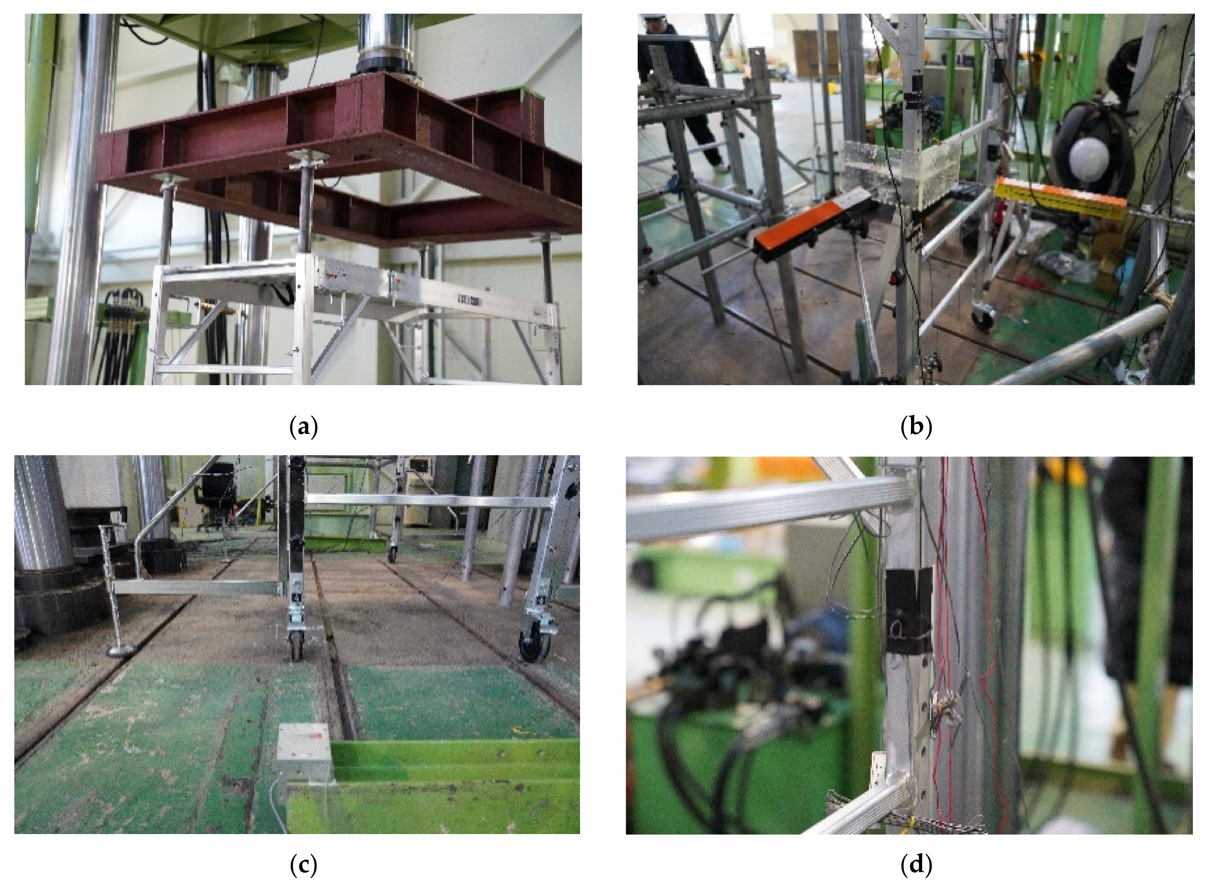
Figure 3 shows the test set-up. A 2000-kN actuator was connected to the specimen and a vertical load was loaded at a speed of 1 mm/min. As shown in Figure 3a, a square frame composed of H-beams was attached to the actuator so that the same compressive load was applied to each vertical member. Because the stiffness of the square frame is an important factor for uniform load transmission, an H-beam of an appropriate size was selected. The dimensions of the H-beam were 200 mm × 200 mm × 10 mm × 16 mm. This was also reinforced by the addition of stiffeners. In addition, the height was adjusted such that the square frame and the specimen were in close contact with each other using a jackbase for a uniform distribution of vertical loads.
The details of the gauges for measuring displacement and strain by conducting the loading test are shown in Figure 4. To measure the horizontal displacement of the vertical members, linear variable differential transformers (LVDTs) were installed at the midpoints of the vertical members of each story so that they were perpendicular to each other in the X- and Y-directions of the horizontal plane. A wire displacement meter was installed in the X-direction to measure the horizontal displacement of the caster wheel. In addition, strain gauges were attached to the vertical member–horizontal member connection and the vertical member–outrigger connection at the specimen bottom to analyze the strain of the vertical member owing to the vertical load.

4. Investigation of the Ultimate Behaviors of Mobile Scaffolds

The experimental results follow the following designations. The designations for the displacement and strain are summarized and marked in Figure 5.

4.1. Failure Mode

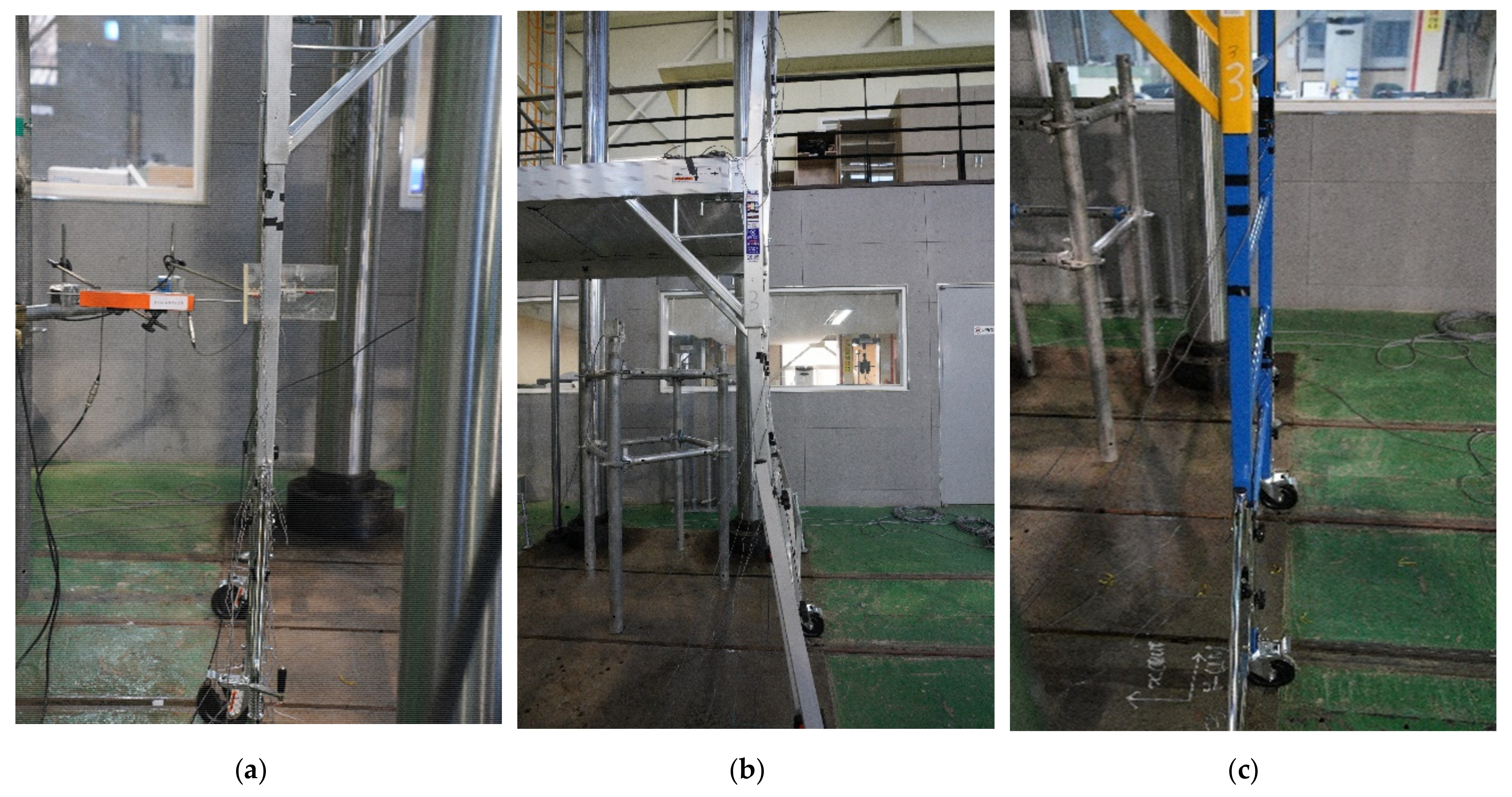
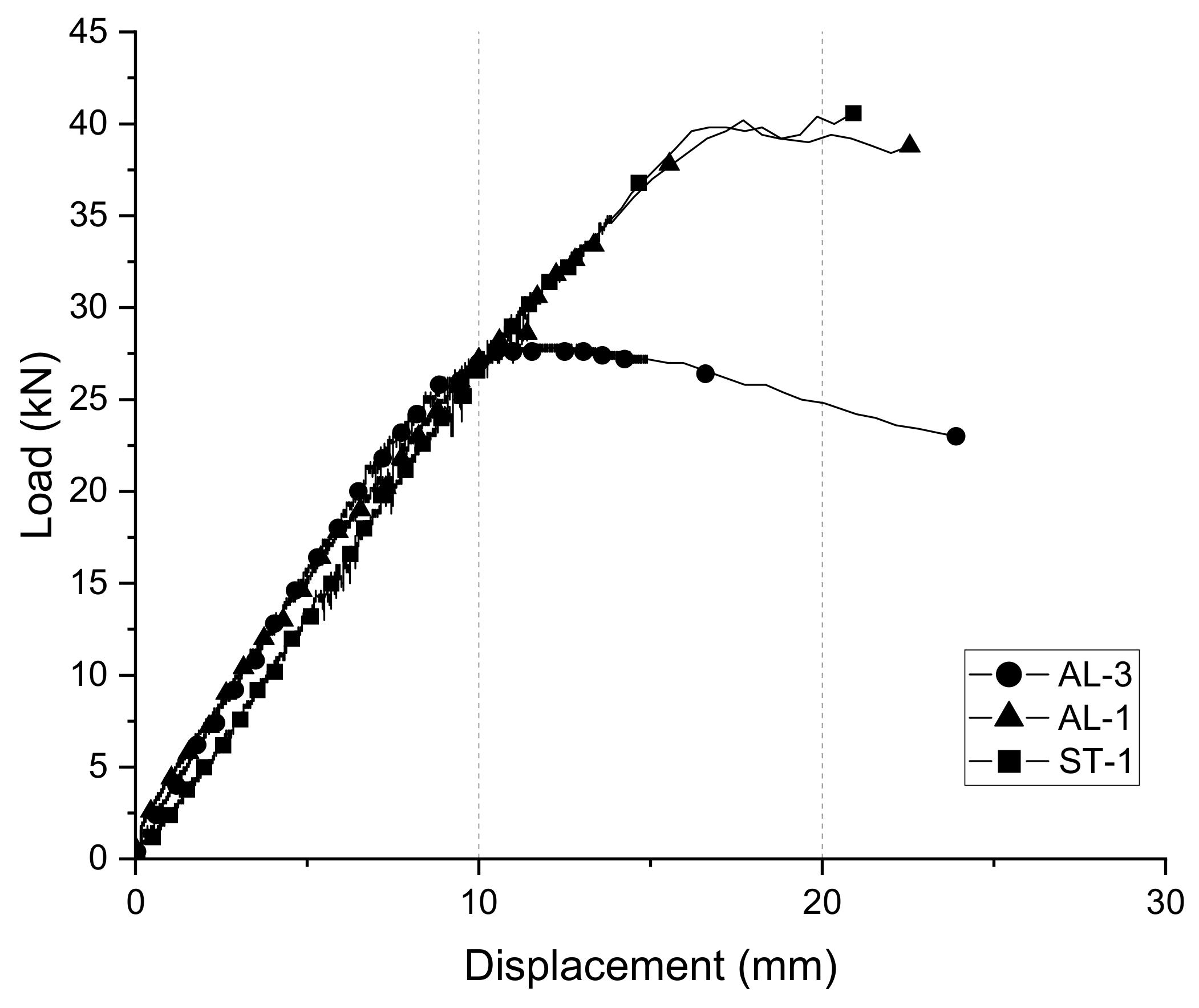
Figure 6 shows the shape of each specimen in the fracture mode. The fracture and buckling shapes of each specimen are marked in Figure 7. The failure modes of the single-story specimens with low-heighted structure and three-story specimens with structures at a height were different. The single-story specimens could no longer withstand the vertical load before buckling of the vertical member occurred, and the wheel was destroyed first. The caster wheels of the aluminum single-story specimen were destroyed under the application of a vertical load of approximately 40.2 kN and those of the steel single-story specimen were destroyed under the application of a vertical load of approximately 40.6 kN. Unlike the failure mode of the single-story aluminum specimen, buckling of the vertical member occurred first before the failure of the caster wheels. Vertical member buckling occurred when a vertical load of approximately 28 kN was applied.

4.2. Load–Displacement Relation

Figure 8 shows the vertical displacement of the structure under an increasing vertical load. AL-1 is an aluminum single-story test specimen, AL-3 is an aluminum three-story test specimen, and ST-1 is a steel single-story test specimen. The tendencies of the initial load–displacement changes before the three specimens reached the ultimate load were similar. The member with the smallest stiffness in the structure dominated the initial stiffness of the structure. Therefore, the stiffness of the initial structure reflects the weakest stiffness of the caster wheels regardless of the material or height of the structure. As mentioned above, the values of the ultimate load of the first stages of aluminum and steel were similar because of the preceding failure of the wheel. The three-story aluminum specimen showed that the buckling of the vertical member occurred earlier than the failure of the wheel and the ultimate load value was lower than that applied to the other specimens. At this time, the vertical displacement of the three-story specimen was approximately 11.6 mm.
If the experiment was performed after the stiffness of the caster wheel was secured to be sufficiently higher than that of the vertical members, the single-story specimens would have different ultimate load results. The lower the story of the fabricated mobile scaffold, the more it is necessary to consider the failure of the caster wheel than the load capacity of the vertical or horizontal members, and the higher the number of stages, the more sufficient consideration should be given to the buckling of the vertical members.

4.3. Horizontal Displacement of Caster Wheels and Vertical Members

Figure 9 shows the horizontal displacements of the vertical members and caster wheels of each specimen subjected to increasing load. The four caster wheels of the aluminum single-story test specimen and steel single-story test specimen had micro-displacements within 5 mm in the horizontal X-direction. When comparing the displacements of the mid-point of the vertical member and the wheel, the displacement of the vertical member was slightly larger in the horizontal X-direction than that of the wheel. This might be the displacement caused by the looseness that existed in the connection part of each member under the application of a vertical load to the test specimens. The horizontal Y-direction displacement hardly occurred compared to the horizontal X-direction displacement.
However, a different pattern from that obtained in the previous experiment appeared in the aluminum three-story test specimen. As shown in Figure 9b, as the vertical load gradually increases, displacement occurs in the same direction for all four caster wheels. From the loading point of approximately 27 kN, the magnitude of the displacement increases rapidly. However, the magnitude of the wheel displacement is not as large as that of the displacement of the vertical member in the X-direction. Therefore, we conclude that the buckling of the vertical member occurred throughout the structure.
Analyzing the difference in the displacement of the mid-point of the vertical member of each story, the vertical members located in the first and second stages of the aluminum three-story specimen had a large displacement, whereas the uppermost vertical member had relatively little displacement, as shown in Figure 10b. Therefore, buckling occurred largely at the lower end of the structure. As shown in Figure 11, displacement occurred in the horizontal Y-direction as well but in a smaller amount.

4.4. Load–Strain Relation

Figure 12 shows the relation between the vertical strain and load of each vertical member of the specimen. The strain gauges were attached to the outer surface of the connection part between the vertical and horizontal members and the connection part between the vertical member and the outrigger to measure the vertical strain. In case of the single story of aluminum and steel specimens, a greater compressive force was generated in the lower part than in the upper part of the vertical member, indicating that warpage occurred in the inward direction in the lower part of the structure.
In case of three-story aluminum, tensile force occurred as the vertical load increased at the upper part of the vertical member, and the lower part received a compressive force for a certain period, and then, the tensile force occurred from the point when a vertical load of approximately 27 kN was applied.
In the case of the aluminum and steel single-story specimens, the caster wheel was excessively deformed at the early stage, and accordingly, a large deformation occurred near the measurement positions (1P_1F_B, 2P_1F_B), the bottom of the vertical member close to the caster wheel. On the other hand, relatively small deformation occurred at the measurement positions (1P_1F_T, 2P_1F_T) of the upper part of the vertical member. Therefore, it was confirmed that the material yield was reached in the cross-section of the vertical member close to the caster wheel.
In the case of the aluminum three-story specimen, the strain reversal due to the buckling of the vertical member was clearly observed. Based on the load-strain curve shown in the figure, it is confirmed that the elastic buckling of the vertical members is the governing failure mode of the three-story fabricated mobile scaffold.
As mentioned above, because the strain gauge is attached to the outer surface of vertical members 1 and 2, the buckling shape of the three-story aluminum test specimen occurred, as shown in Figure 13.

4.5. FEM Analysis

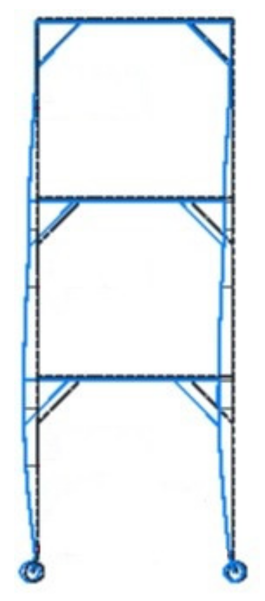
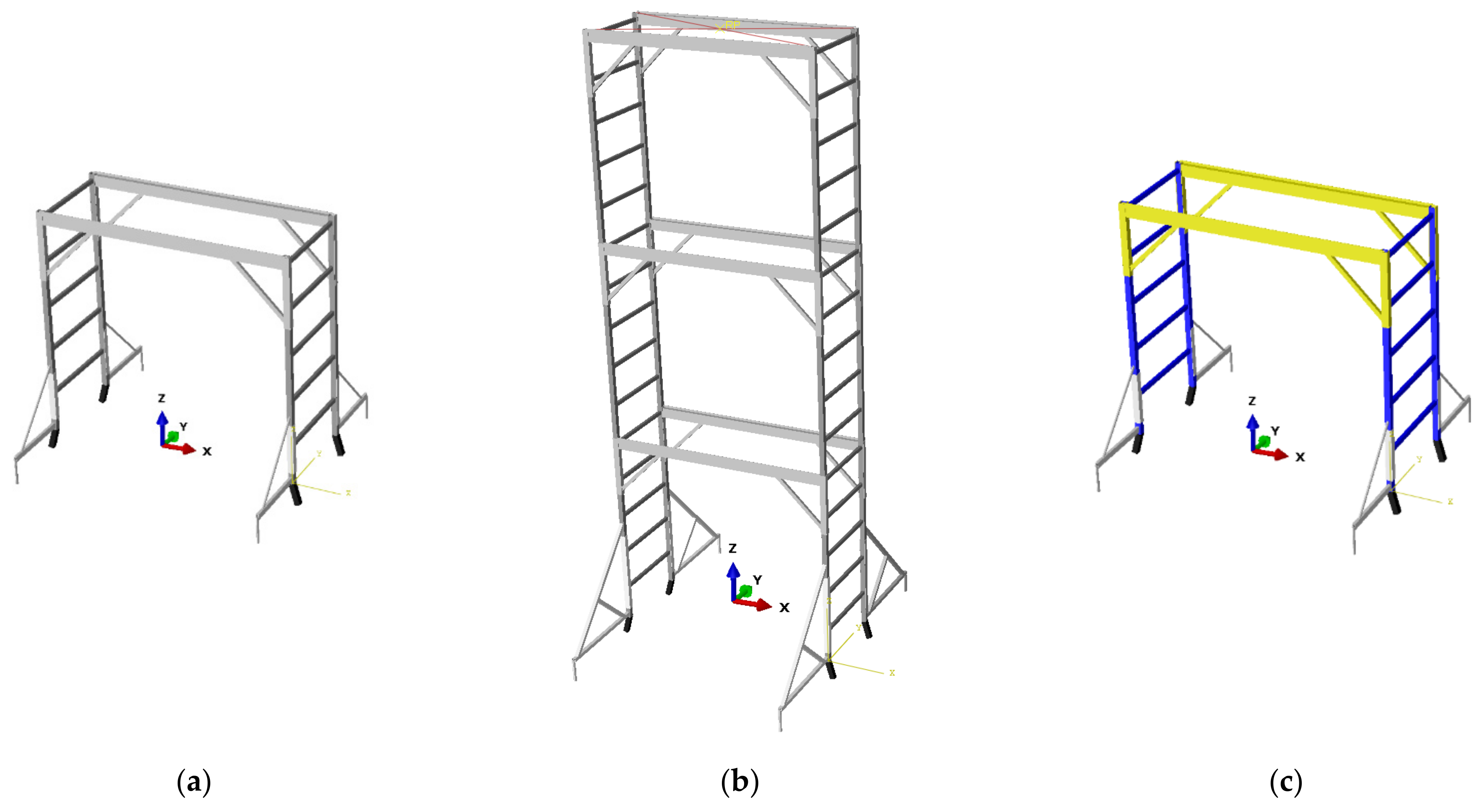
FEM analysis was performed to verify the ultimate modes and load carrying capacities of the structure obtained as a result of the actual experiment. The FE analysis was conducted using ABAQUS V2019. The numerical models include the vertical, horizontal and diagonal members shown in Figure 14. All the line members were modeled using a three-dimensional nonlinear beam element. To investigate the ultimate behaviors of the scaffold models, nonlinear inelastic analysis was conducted. For the nonlinear inelastic analysis, the arc-length method was adopted as the incremental-iterative analysis scheme. Figure 15 and Figure 16 show the deformed shapes and load-displacement curves of the models obtained using nonlinear inelastic analysis.
In our FEM models, the caster wheel was not included because of the complexity of the material model, geometric shape, and contact and boundary conditions of the urethane caster wheels. Thus, we conducted nonlinear analysis to observe the effects of the urethane caster wheels on the ultimate behaviors of the fabricated mobile scaffolds. Comparing the analysis and experiment results, we can conclude the effects as below:
(1)
For the single-story scaffolds, there are significant differences in the ultimate load capacity and stiffness. Without the wheel, the material yield was observed as the governing ultimate mode. However, in the experiments, the early failure of the caster wheels leads to the ultimate states of the scaffolds.
(2)
For the three-story scaffold, the comparison does not show the significant differences in the load-carrying capacities although the numerical model does not include the caster wheels. Therefore, we concluded that the buckling of the vertical members is the primary failure mode for the multi-story models. Despite this, there is a stiffness difference between the numerical and experimental models for the three-story scaffolds. This is due to the urethane caster wheels.

5. Discussion and Conclusions

In this study, an experiment was conducted to analyze the characteristics of the structural and ultimate behaviors of the fabricated mobile scaffolds. The experiment was conducted on three specimens under the application of vertical loads. A comparative analysis was performed for each material and number of fabricated stories by using comparative models of aluminum single-story, aluminum three-story, and steel single-story specimens. When vertical loads were applied according to parameter changes, the experimental results, such as vertical displacement of the members, horizontal displacement of members, and strain of vertical members, were analyzed. The conclusions are summarized as follows.
  • In the case of the aluminum three-story specimen, as the applied load increased, buckling occurred in the vertical member and the structural behavior that led to the extreme state was clearly revealed. However, in the cases of the aluminum single-story and steel single-story specimens, the caster wheel was destroyed before the buckling deformation of the vertical members. In other words, if the capacity of the caster wheel was enhanced, the single-story specimens also entered an extreme state owing to the buckling of the vertical members. Therefore, a lower height of the fabricated mobile scaffold leads to a better performance of the caster wheel, and a higher structure makes the buckling failure of the vertical member an important factor in determining the working load.
  • The difference between the ultimate load of the aluminum single-story test specimen and that of the steel single-story test specimen was small (~ 1%); however, it is likely that similar values appeared owing to the destruction of the caster wheel. If a stronger caster wheel is used for the single-story scaffolds, a larger load-carrying capacity than that of the current models is expected. Although the caster wheel failure did not occur, the ultimate load of the three-story aluminum specimen was approximately 30% smaller than that of the single-story specimens owing to buckling failure.
  • In accordance with the safety certification standards of Korea, the appropriate work class of the products used in the experiment was classified based on the unit load per work class. All single-story specimens satisfied the working load corresponding to work class 3; thus, it is possible to work with heavy resources. In contrast, the aluminum three-story test specimen satisfies the working load corresponding to work grade 2 and is capable of heavy work requiring construction resource loading.
  • Although the Korean safety certification standards only judge whether the performance of each member is satisfied, the material, length of the member, size of the cross-section, size of the fabricated product, and connection details of each member are not considered. Therefore, it is difficult to identify and handle the possibility that the failure of the caster wheel may occur before the buckling of the vertical member, as in the experimental results of the single-story test specimens. Therefore, it is necessary to re-establish reasonable safety certification standards by understanding the extreme behavioral characteristics of the entire structure.
  • If more specimens, labor, and time required for the experiment were given, it would be possible to conduct a structural test for a fabricated mobile scaffold with various materials and structures. In addition, it is possible to establish generalized performance standards and derive the results for various load conditions.

Author Contributions

Conceptualization, S.K.; methodology, H.K., J.L. (Jeonghyeon Lim) and Y.J.K.; software, Y.J.K.; validation, H.K., J.L. (Jeonghyeon Lim) and S.K.; formal analysis, H.K. and J.L. (Jeonghyeon Lim); investigation, H.K., J.L. (Jeonghwa Lee), S.K.; resources, S.K.; data curation, H.K. and J.L. (Jeonghwa Lee); writing—original draft preparation, H.K.; writing—review and editing, H.K. and S.K.; visualization, H.K.; supervision, S.K.; project administration, S.K.; funding acquisition, S.K. All authors have read and agreed to the published version of the manuscript.

Funding

This research was funded by the Occupational Safety and Health Certification Institute of Korea Occupational Safety and Health Agency.

Institutional Review Board Statement

Not applicable.

Informed Consent Statement

Not applicable.

Data Availability Statement

Data are contained within the article.

Acknowledgments

This research was conducted by the research project of Occupational Safety & Health Certification Institute of Korea Occupational Safety and Health Agency.

Conflicts of Interest

The authors declare no conflict of interest.

References

  1. Peng, J.; Chan, S.L.; Wu, C. Effects of geometrical shape and incremental loads on scaffold systems. J. Constr. Steel Res. 2007, 63, 448–459. [Google Scholar] [CrossRef]
  2. Buitrago, M.; Sagaseta, J.; Adam, J.M. Effects of sudden failure of shoring elements in concrete building structures under construction. Eng. Struct. 2018, 172, 508–522. [Google Scholar] [CrossRef] [Green Version]
  3. Beale, R.G. Scaffold research—A review. J. Constr. Steel Res. 2014, 98, 188–200. [Google Scholar] [CrossRef] [Green Version]
  4. Gylltoft, K.; Mroz, K. Load-carrying capacity of scaffolds. Struct. Eng. Int. 1995, 5, 37–42. [Google Scholar] [CrossRef]
  5. Lightfoot, E.R.; Olivetto, G.; Merchant, W. The collapse strength of tubular steel scaffold assemblies. Proc. Inst. Civil. Eng. 1977, 63, 311–329. [Google Scholar] [CrossRef]
  6. Yu, W.; Chung, K.F. Prediction on load carrying capacities of multi-storey door-type modular steel scaffolds. Steel Compos. Struct. 2004, 4, 471–487. [Google Scholar] [CrossRef]
  7. Halperin, K.M.; McCann, M. An evaluation of scaffold safety at construction sites. J. Saf. Res. 2004, 35, 141–150. [Google Scholar] [CrossRef] [PubMed]
  8. Rubio-Romero, J.C.; Gámez, M.C.R.; Carrillo-Castrillo, J.A. Analysis of the safety conditions of scaffolding on construction sites. Saf. Sci. 2013, 55, 160–164. [Google Scholar] [CrossRef]
  9. Harung, H.S. The strength of scaffold towers under vertical loading. Struct. Eng. 1975, 53, 23–30. [Google Scholar]
  10. Weesner, L.; Jones, H. Experimental and analytical capacity of frame scaffolding. Eng. Struct. 2001, 23, 592–599. [Google Scholar] [CrossRef]
  11. Kim, S.-E.; Kang, K.-W.; Lee, D.-H. Full-scale testing of space steel frame subjected to proportional loads. Eng. Struct. 2003, 25, 69–79. [Google Scholar] [CrossRef]
  12. Chandrangsu, T.; Rasmussen, K.J. Investigation of geometric imperfections and joint stiffness of support scaffold systems. J. Constr. Steel Res. 2011, 67, 576–584. [Google Scholar] [CrossRef]
  13. Zhang, H.; Rasmussen, K.J. System-based design for steel scaffold structures using advanced analysis. J. Constr. Steel Res. 2013, 89, 1–8. [Google Scholar] [CrossRef]
  14. Won, B.-H.; Yoon, K.-W.; Jeon, S.-S. Survey and improvement scheme for safety certification system of temporary equipment and materials. J. Korea Acad. Coop. Soc. 2016, 17, 92–102. [Google Scholar] [CrossRef]
  15. Soeiro, M.A.R.; Holanda, A.S.d.; Parente Junior, E. Nonlinear analysis of steel scaffolds for shoring of concrete structures. REM Int. Eng. J. 2017, 70, 19–26. [Google Scholar] [CrossRef] [Green Version]
  16. Dewobroto, W.; Chendrawan, W. Ultimate load capacity analysis of steel scaffoldings using direct-analysis method. Pract. Period. Struct. Des. Constr. 2018, 23, 04018028. [Google Scholar] [CrossRef]
  17. Liu, H.; Meng, Y.; Jia, L.; Chen, Z.; Liu, Q.; Wen, S. Structural behavior of steel tube and coupler scaffolds with stability strengthening details. Int. J. Steel Struct. 2018, 18, 79–95. [Google Scholar] [CrossRef]
  18. Won, J.-H.; Lee, H.D.; Choi, M.-K.; Park, M.C. Flexural strength and rotational stiffness estimation of joint between vertical and horizontal members in system support. J. Korean Soc. Saf. 2018, 33, 46–53. [Google Scholar] [CrossRef]
  19. Bong, J.K.; Lee, H.D.; Kim, S.; Mha, H.-S.; Yim, D.-K.; Won, J.-H. Probabilistic characteristics of moment capacity and rotational stiffness of wedge joints used in support systems reflecting reused members. Appl. Sci. 2019, 9, 4056. [Google Scholar] [CrossRef] [Green Version]
  20. Do, L.H.; Won, J.-H.; Jang, N.-G.; Mha, H.-S.; Jeong, S.-c.; Kim, S. Experimental study on load carrying capacity enhancement of system supports considering full installation of bracing members. Int. J. Steel Struct. 2020, 20, 2051–2067. [Google Scholar] [CrossRef]
  21. Jeong, S.C.; Kwon, J.H.; Won, J.H.; Kwon, Y.J. Feasibility analysis for the introduction of safety certification system for assembled temporary equipment and materials. J. Korean Soc. Saf. 2020, 35, 32–42. [Google Scholar] [CrossRef]
  22. KICT. KDS 21 60 00. Design Standards for Scaffolding and Safety Facilities; Ministry of Land, Infrastructure and Transport: Sejong, Korea, 2020.
  23. BSI. BS EN 1004-1. Mobile Access and Working Towers Made of Prefabricated Elements-Materials, Dimensions, Design Loads, Safety and Performance Requirements; British Standards Institution: London, UK, 2020. [Google Scholar]
  24. AS. AS/NZS 1576.1. Scaffolding General Requirements; Standard Australia: Sydney, Australia, 2019. [Google Scholar]
  25. Prabhakaran, U.; Beale, R.; Godley, M. Analysis of scaffolds with connections containing looseness. Comput. Struct. 2011, 89, 1944–1955. [Google Scholar] [CrossRef] [Green Version]
  26. Pieńko, M.; Błazik-Borowa, E. Verification of the numerical model of insert-type joint of scaffolding in relation to experimental research. AIP Conf. Proc. 2018, 1922, 080003. [Google Scholar] [CrossRef]
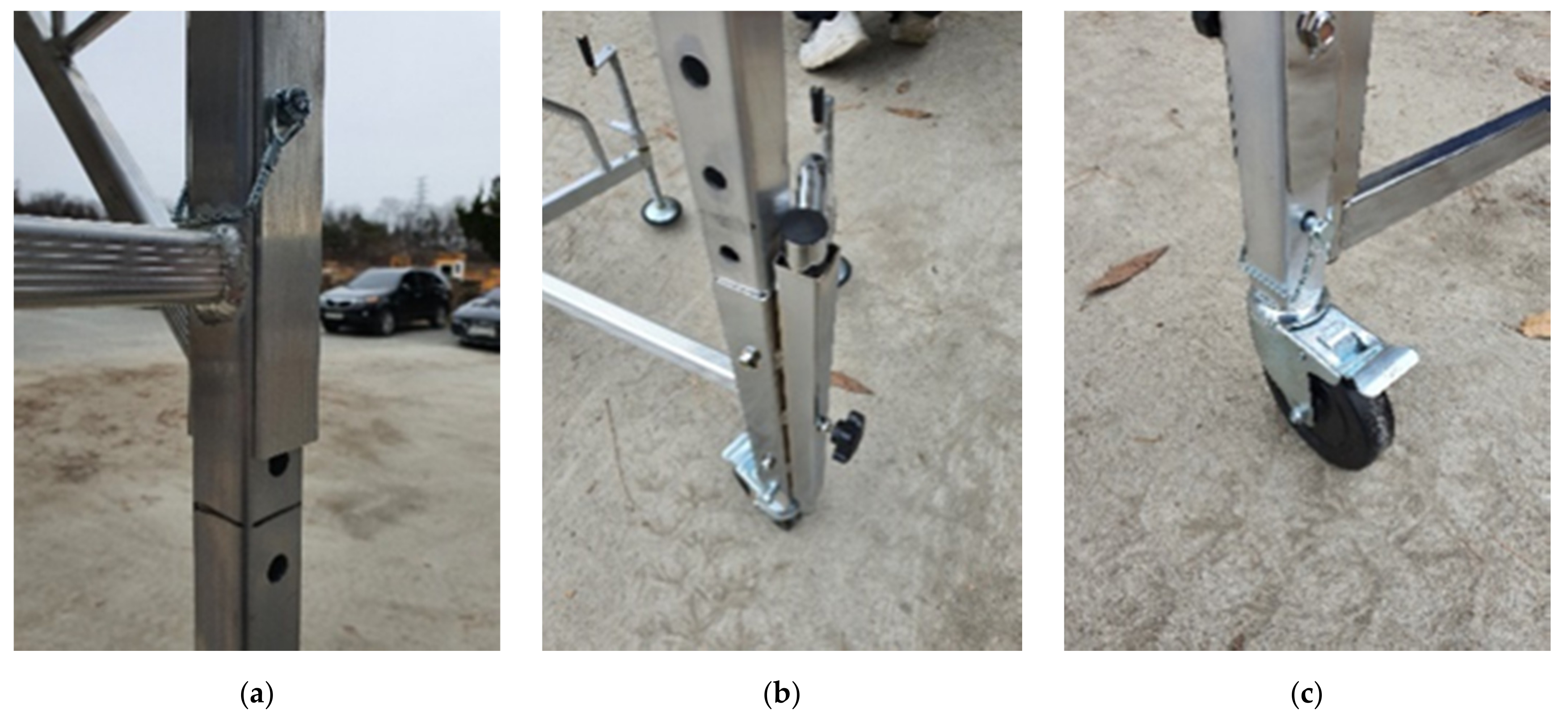
Figure 1. Details of the connection part of the aluminum test specimen: (a) vertical–horizontal member connection; (b) vertical material–outrigger connection; (c) vertical member–caster wheel connection.
Metals 11 00851 g001
Figure 2. Details of the connection part of the steel test specimen: (a) vertical–horizontal member connection; (b) vertical material–outrigger connection; (c) vertical member–caster wheel connection.
Metals 11 00851 g002
Figure 3. Preparations for experimental measurements. (a) H-beam frame attached to the actuator; (b) LVDTs attached to vertical member; (c) wire displacement meter attached to the caster wheel; (d) strain gauge attached to the vertical member.
Metals 11 00851 g003
Figure 4. Location of sensors: (a) mounting positions for sensor; (b) mounting direction of LVDTs.
Metals 11 00851 g004
Figure 5. Designations for the experimental results: (a) designation for the displacement; (b) designation for the strain.
Metals 11 00851 g005
Figure 6. Failure configuration of caster wheel: (a) aluminum single-story specimen; (b) aluminum three-story specimen; (c) steel single-story specimen.
Metals 11 00851 g006
Figure 7. Failure configuration of vertical member: (a) aluminum single-story specimen; (b) aluminum three-story specimen; (c) steel single-story specimen.
Metals 11 00851 g007
Figure 8. Load–vertical displacement curves of specimens.
Metals 11 00851 g008
Figure 9. Load-X-direction displacement curves of the caster wheel: (a) aluminum single-story specimen; (b) aluminum three-story specimen; (c) steel single-story specimen.
Metals 11 00851 g009
Figure 10. Comparison load-X-direction displacement relation with vertical member and caster wheel: (a) aluminum single-story specimen; (b) aluminum three-story specimen; (c) steel single-story specimen.
Metals 11 00851 g010
Figure 11. Load-Y-direction displacement curves of the vertical member: (a) aluminum single-story specimen; (b) aluminum three-story specimen; (c) steel single-story specimen.
Metals 11 00851 g011
Figure 12. Comparison of load-strain relation in vertical members: (a) aluminum single-story specimen; (b) aluminum three-story specimen; (c) steel single-story specimen.
Metals 11 00851 g012
Figure 13. Buckling shape of aluminum three-story specimen.
Metals 11 00851 g013
Figure 14. Finite element models: (a) aluminum single-story specimen; (b) aluminum three-story specimen; (c) steel single-story specimen.
Metals 11 00851 g014
Figure 15. Deformed shape of the simulated FE models: (a) aluminum single-story specimen; (b) aluminum three-story specimen; (c) steel single-story specimen.
Metals 11 00851 g015
Figure 16. Comparison of load‒displacement relationship between FEM analysis results and test results: (a) aluminum single-story specimen; (b) aluminum three-story specimen; (c) steel single-story specimen.
Metals 11 00851 g016
Table 1. Vertical load per unit area according to work type.
Work TypeVertical Load Per Unit Area
Light work where only light tools are used1.25 kN/m2 or more
Heavy work requiring construction material loading2.5 kN/m2 or more
Heavy work resources3.5 kN/m2 or more
Table 2. Classes of uniformly distributed load.
Load ClassUniformly Distributed Load, q
21.5 kN/m2
32.0 kN/m2
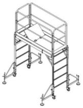
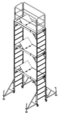
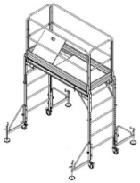
Table 3. Schematic view of specimens.
SpecimenAL-1AL-3ST-1
Shape Metals 11 00851 i001 Metals 11 00851 i002 Metals 11 00851 i003
Note1-story aluminum3-story aluminum1-story steel
Height1918 mm5048 mm1918 mm
Width1910 mm × 698 mm1910 mm × 698 mm1910 mm × 698 mm
Table 4. Material properties and dimensions of test specimens.
SpecimenAluminum (1-Story, 3-Story)Steel (1-Story)
Vertical MemberHorizontal MemberVertical MemberHorizontal Member
MaterialA6063A6063SS275SS275
Yield strength
(MPa)
214214275275
Length
(mm)
1650188116501878
Cross-section
(mm)
39.5 × 39.4100 × 32.538 × 38100 × 38
Thickness
(mm)
32.51.71.7
Table 5. Material properties of caster wheel.
CategoryCaster Wheel
Wheel materialUrethane
Wheel diameterØ125 mm
Fixed shaft materialSS275
Fixed shaft Ø33 mm × L95 mm
Table 6. Material properties of outrigger.
CategoryOutrigger for 1-Story ScaffoldOutrigger for 3-Story Scaffold
MaterialSS275SS275
Size(mm)480 × 490.2820 × 780
Publisher’s Note: MDPI stays neutral with regard to jurisdictional claims in published maps and institutional affiliations.