Study of Metallic Housing of the Adder Gearbox to Reduce the Noise and to Improve the Design Solution
Abstract
1. Introduction
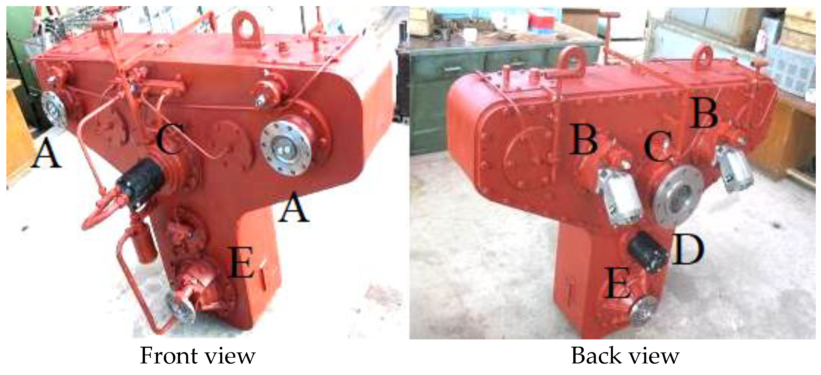
2. Presentation of the Adder Box
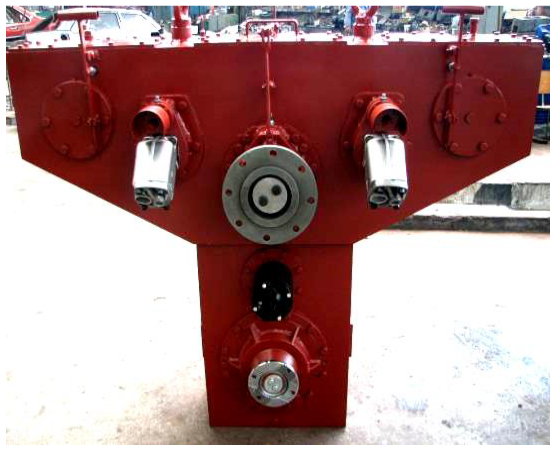
- The input shafts, which receive the movement from the gearboxes of the power groups, by means of Cardan transmissions, have the possibility to engage or disengage the power groups according to the needs. On these shafts are mounted gimbal flanges to which the power groups and gears are coupled.
- Intermediate shafts I, which transmit the power flow to the power take-off shaft and drive two Parker type F1-51-L 378 1051 hydraulic pumps at the same time, which can be coupled as required.
- The shaft of the power take-off, which ensures the transmission of the power flow to the drilling rig and to the drive axles, by means of two gears provided with coupling mechanisms and the Cardan flange for driving the drilling rig. On the side opposite the drive flange of the unit, there is a pump with radial pistons ZF 8607.955.108., which ensures the lubrication of the box.
- Intermediate shaft II, which ensures, by means of a gear, the transmission of the power flow to the interaxial differential, driving at the same time the additional steering pump and the gear with crossed axes for the velocograph.
- The output shaft, which contains the interaxial differential, the drive toothed ring, the differential locking mechanism, and the Cardan flanges related to the Cardan transmissions to the chassis axles.
- Maximum input moment: 2 × 20,000 Nm;
- Maximum input speed: 2100 rpm;
- Transmission ratio to shaft B: 1.275;
- Transmission ratio to shaft C: 1.4;
- Transmission ratio to shaft E: 1.1;
- Mass: approx. 1650 kg.
- The transmission of the vibrations produced in the structure is done mainly on the inner path, i.e., through gears in gears, bearings from the bearings, to the walls of the housing. This demonstrates why, especially in transmission units that transmit high moments (hence the case of the CSD 4000 adder gearbox), the importance of acoustic optimization of the housing structure is important in order to obtain a gear that has a low noise structure.
- The vibratory properties of the components through which the vibrations are transmitted are decisive in their transmission. In current gearboxes or distribution boxes, which are mainly characterized by rigid connections between all their parts, virtually all internal components contribute to noise radiation.
- The resulting noise will depend on the vibration properties of the parts that make up the structure of the adder box housing. Therefore, determining the vibration characteristics of the carcass structure is of major importance in determining the noise transmission mechanism.
- Considered as a vertical beam, the structure of the housing of the adder box is much more rigid when bending in the vertical plane transverse to the longitudinal axis of the vehicle than in the vertical longitudinal plane to the longitudinal axis of the vehicle. Additionally, the excitation forces act perpendicularly on the walls of the housing, thus constituting a major area of noise radiation. Thus, the bending waves in the longitudinal vertical plane are the main causes of the generation of structural noise.
- The study of the distribution of the structural noise on the surface of the box of the summing box is particularly useful in the design of structural measures. The highest vibrations occur in the power take-off area, between the walls of the main shaft bearings.
3. Structural Analysis of the Adder Box Housing
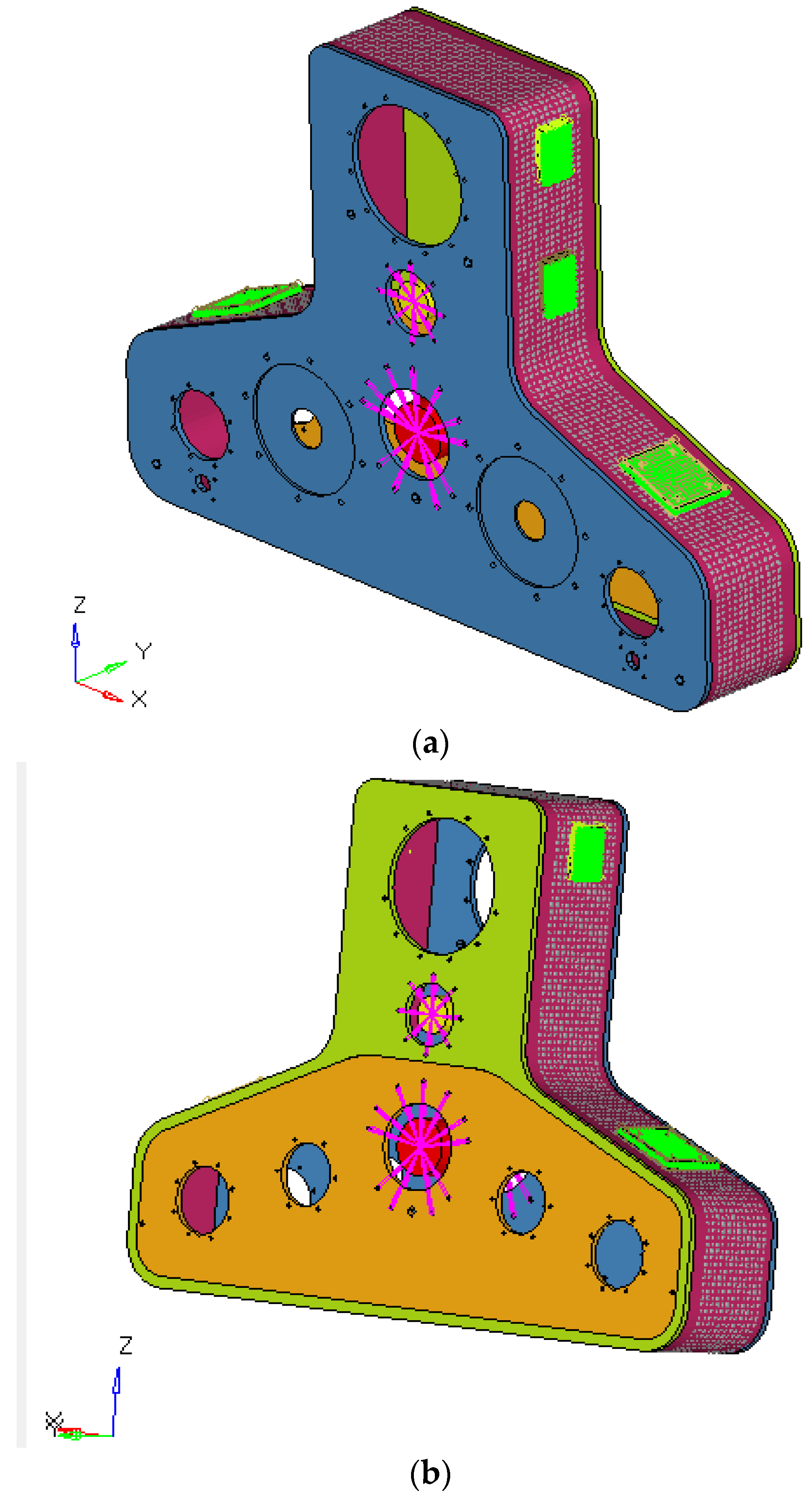
3.1. Static Analysis of the Body of the Adder Gearbox
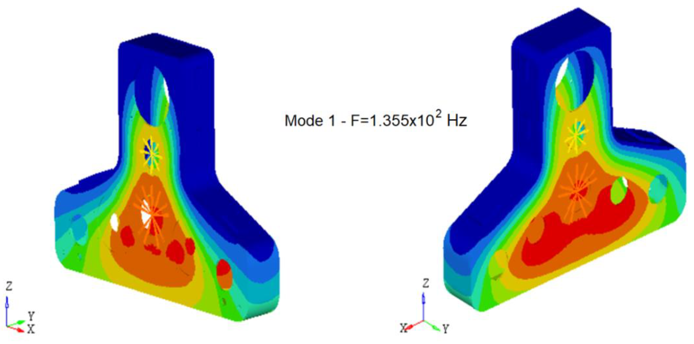
3.2. Modal Analysis of the Adder Gearbox
- The structural analysis highlighted the distribution of unitary efforts on the surfaces of the box housing.
- For the maximum load of the box (maximum transmitted moment), the greatest efforts are distributed in the power take-off area.
- The highest value of the effort is 88.229 N/mm2 in the area of the large cover assembled by screws, close to the left side edge.
- The housing material is OL37.3 and has an operating resistance limit or unlimited fatigue strength (in the case of the carcass, which is made of welded elements) of maximum 13 daN/mm2.
- The maximum stresses in the material of the adder box housing must not exceed the unlimited fatigue strength estimated at 13 daN/mm2 for the material OL37.3.
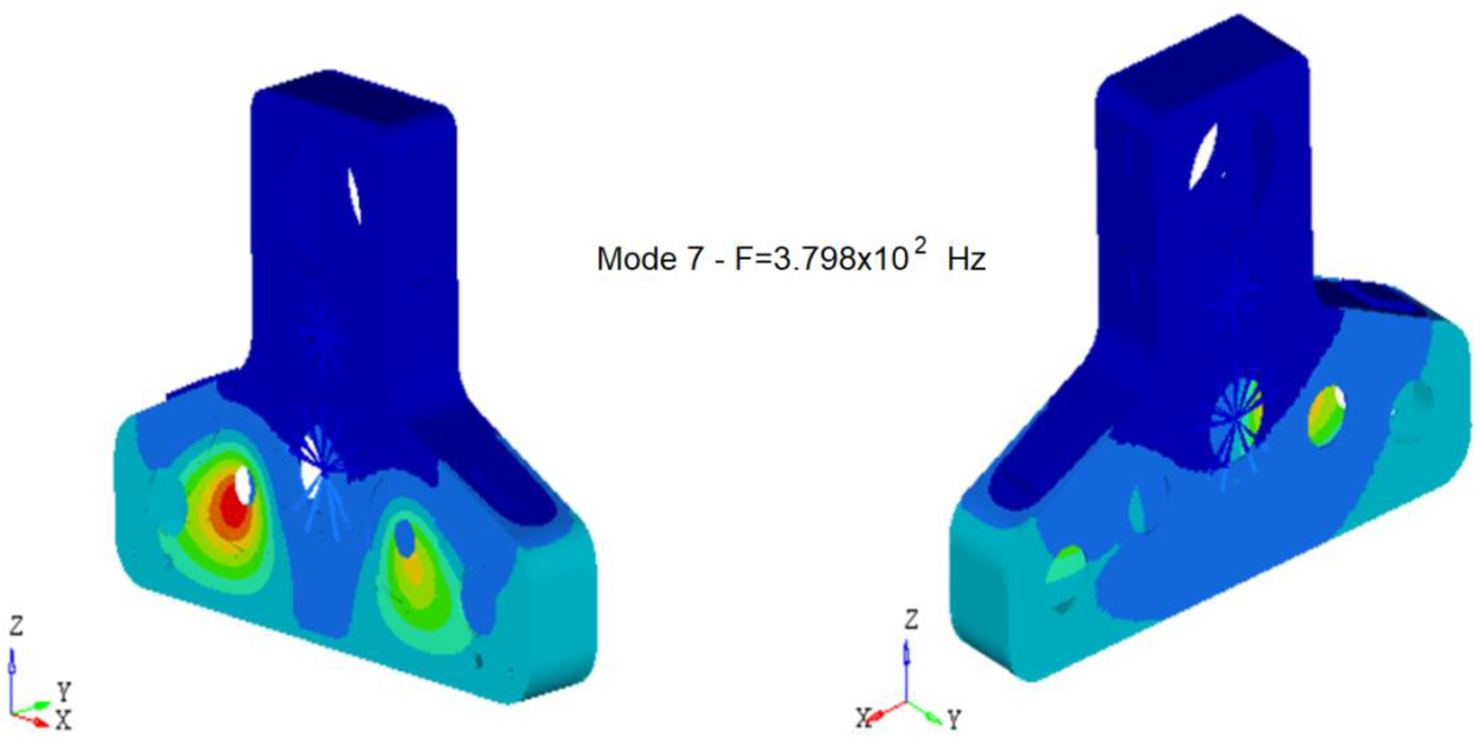
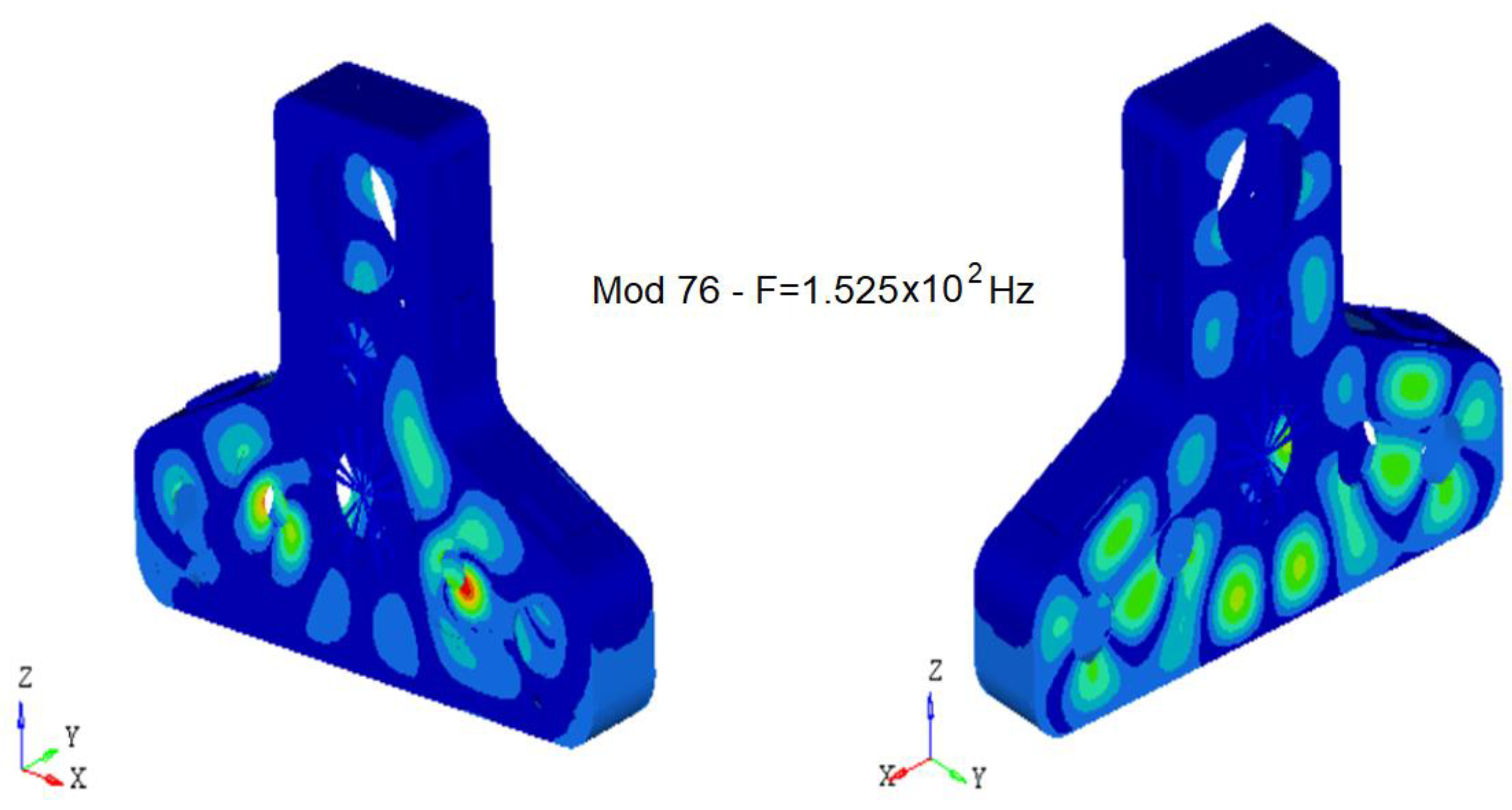
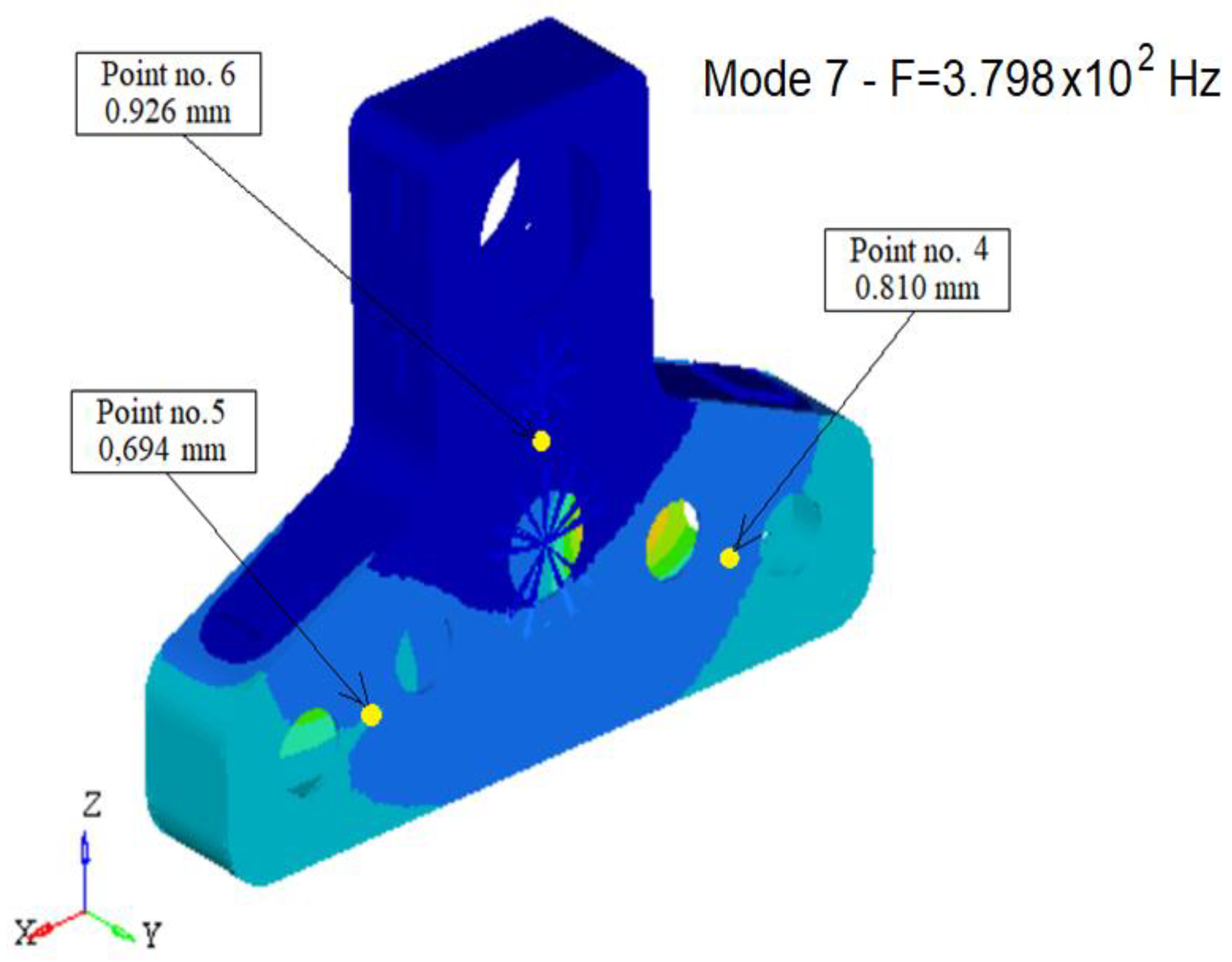
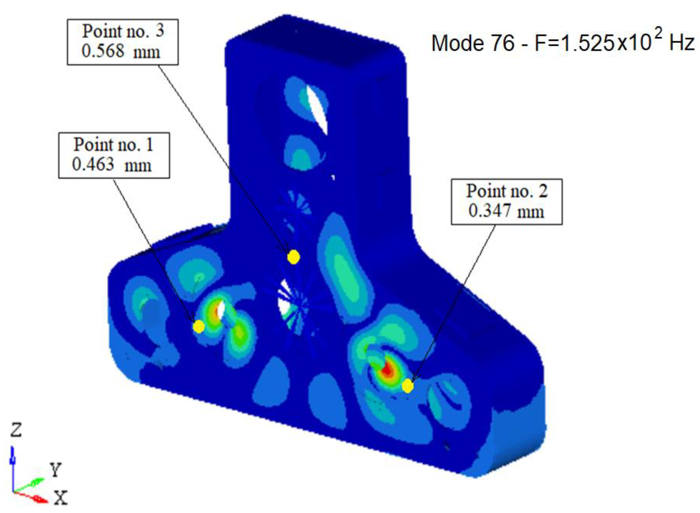
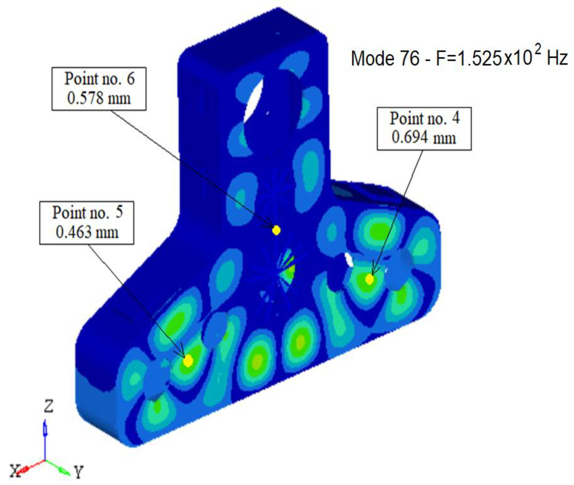
- The modal analysis determined 105 eigenmodes of vibration in the frequency range from 30 to 2000 Hz.
- In the field of low frequencies, the housing has fewer modes of vibration, but the amplitudes of vibration are higher at low frequencies.
3.3. Experimental Tests
- The eigenfrequencies of the structure of the housing of the adder gearbox to which correspond maximum values of the noise radiated by its surfaces.
- Radiated noise from the housing surfaces.
- The amplitudes of the vibration displacements of the surfaces of the box structure of the adder gearbox and their distribution on the analyzed surface.
- Experimental analysis of eigenfrequencies.
- Measurement and experimental analysis of the noise radiated by the housing surfaces.
- Determination of the eigenfrequencies to which correspond maximum values of noise radiated by the housing surfaces.
- Measurement of vibration displacements of the housing surfaces.
- Comparison of the values of the amplitudes of the vibrations of the housing surfaces obtained by simulation in Section 3.3, with the measured values.
- A large number of measuring points would be needed.
- The number of measurements performed simultaneously would be restricted by the capacity of the available equipment, which must ensure the simultaneous transfer of the measured values. Additionally, in order to establish the relationships between the phases, it would be necessary that the measurements be performed against a reference quantity.
- It would not possible to specify how many measuring points need to be analyzed, because it would be impossible to fully describe all the details of the vibration modes.
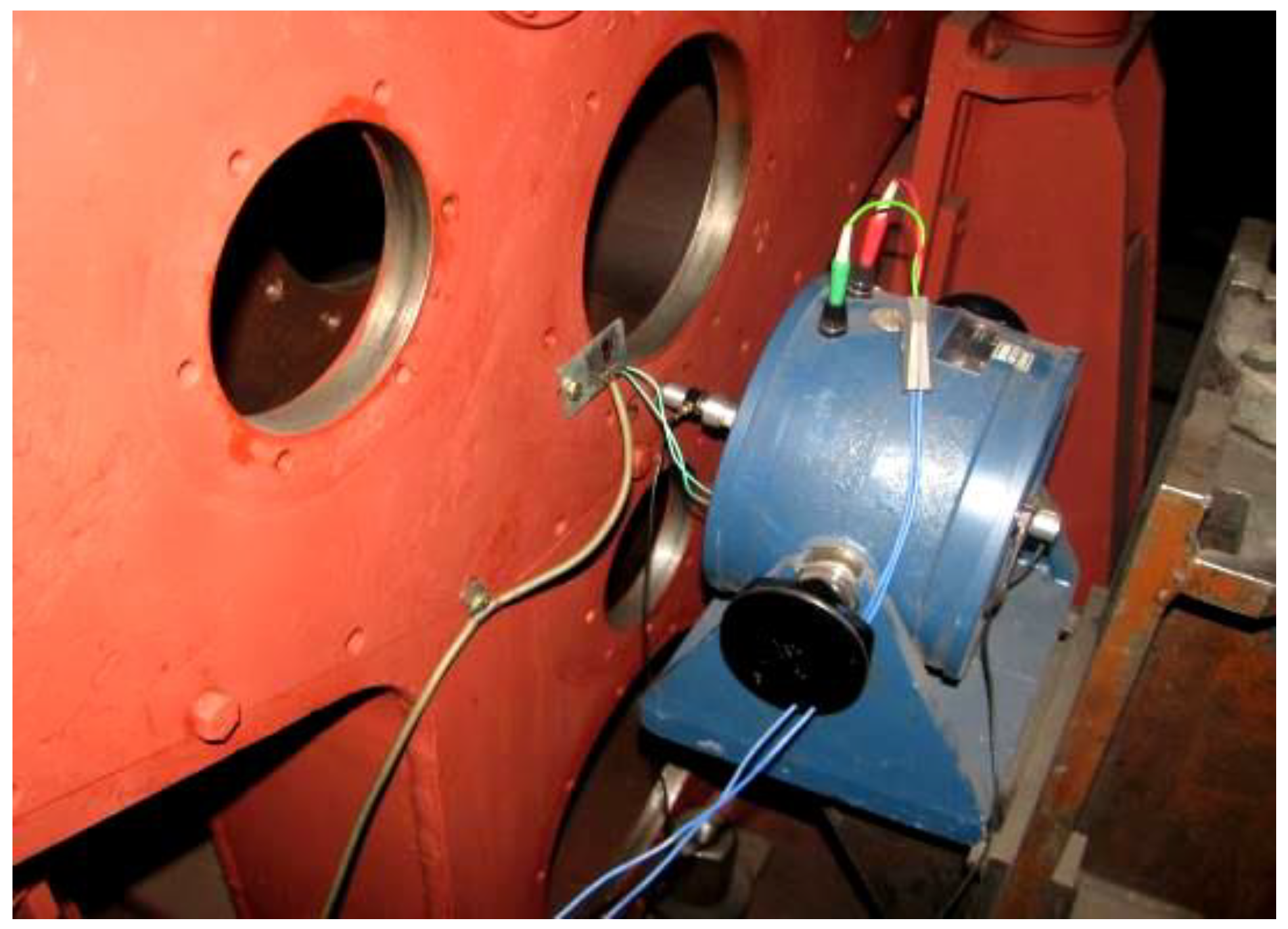
- An electrodynamic exciter.
- An impedance transducer.
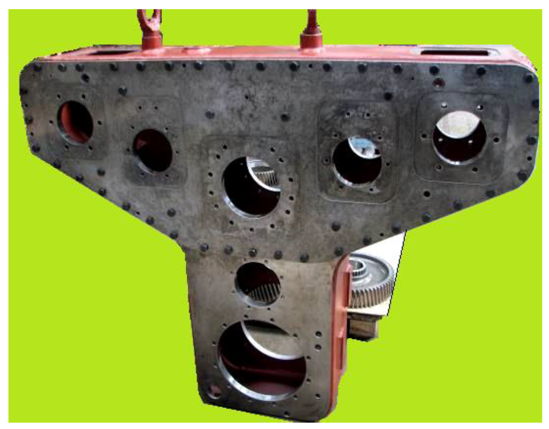
- Adder gearbox housing.
- Frequency response sensitivity: ±0.2 dB (with antialiasing filtering).
- Number of spectral lines: 400.
- Linear mediation: for a number of 2048 mediations, the relative error of the obtained power spectral density is 1.1% or 0.1 dB.
- Signal shape: sinusoidal.
- Constant velocity: vex = 4.10−3 m/s (rms value).
- Exponential back and forth variation of the excitation signal frequency with the speed of 1 oct/min, in two domains: 30 Hz–500 Hz with the resolution 1.25 Hz, and 300 Hz–2000 Hz with the resolution: 5 Hz.
- Signal shape: rectangular.
- Constant speed: vex = 4.10−3 m/s (rms value).
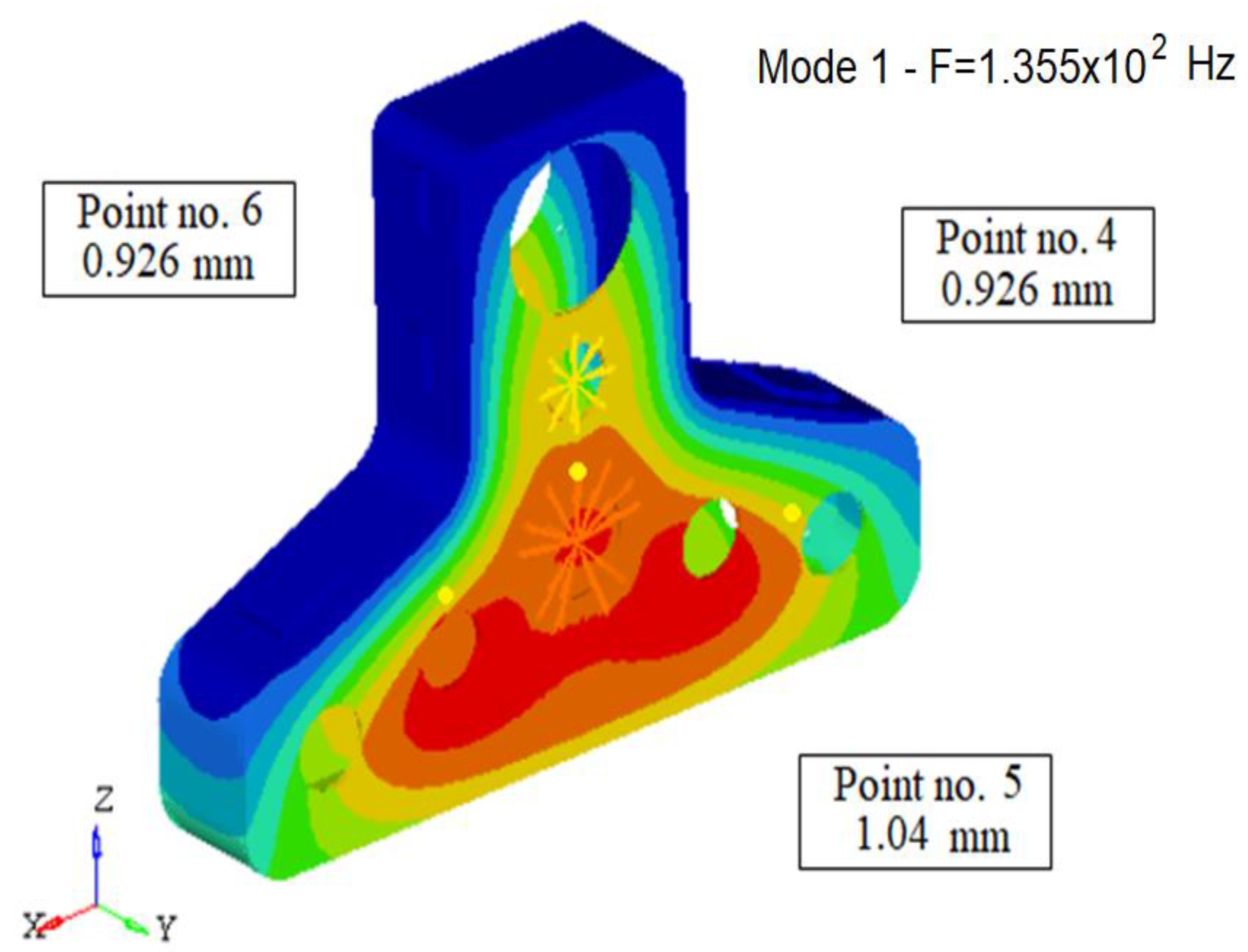
- At two fixed resonance frequencies of the rear surface of the housing, determined experimentally using the mechanical impedance measurement technique: f1 = 395 Hz and f2 = 1550 Hz.
3.4. Measurement of Displacements on the Front Surface of the Housing
- Signal shape: rectangular.
- Constant speed: vex = 4.10−3 m/s.
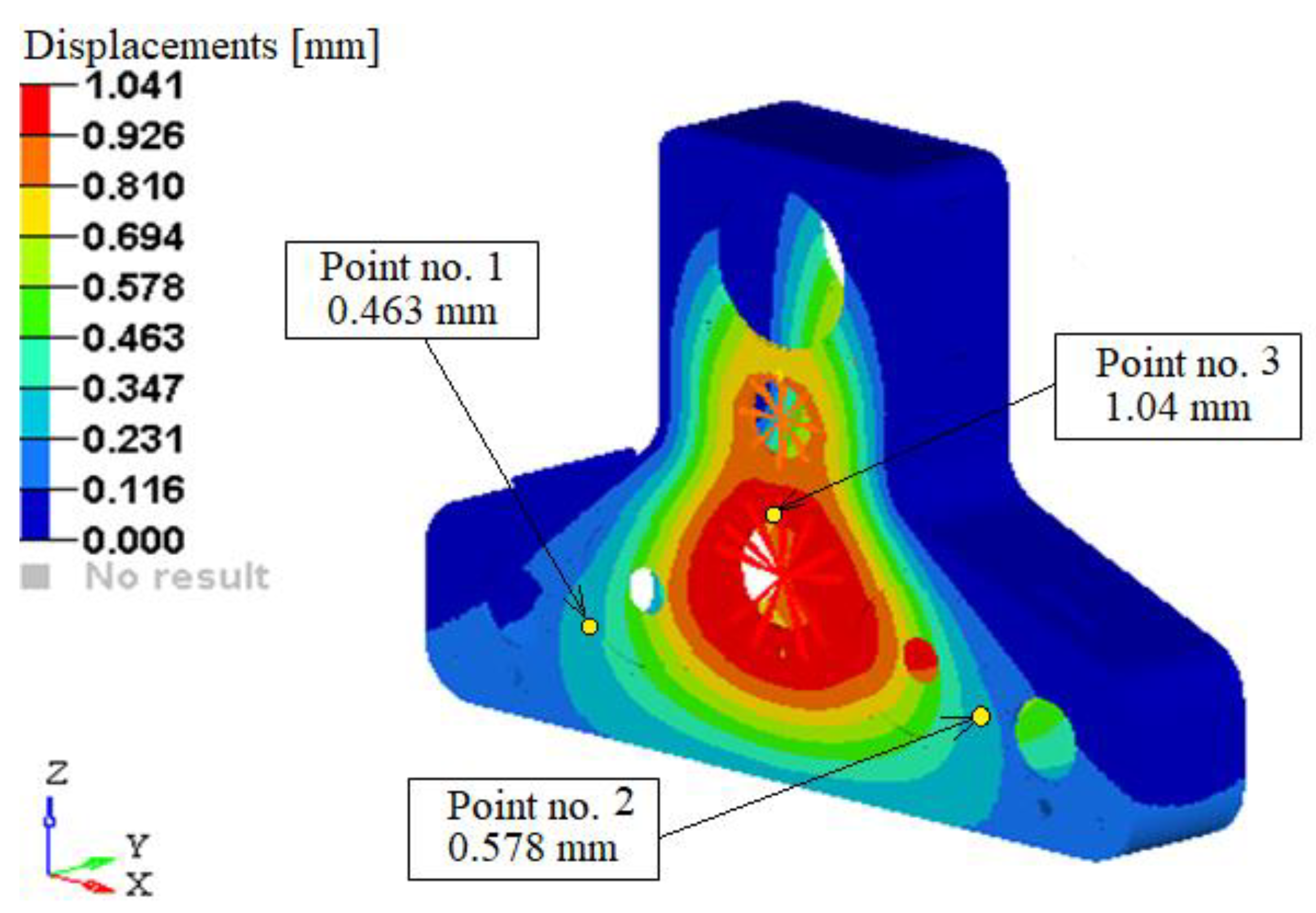
- At two fixed resonant frequencies of the front surface of the housing, determined experimentally using the mechanical impedance measurement technique: f1 = 395 Hz and f2 = 1525 Hz.
3.5. Comparison of the Values of the Vibration Displacements of the Surfaces of the Adder Box Housing Obtained by Simulation with the Experimentally Measured Values
- 5.1
- Analysis of the vibration behavior of the structure of the adder box housing.
- 5.2
- Measurement of the amplitudes of the displacements on the surfaces of the adder box housing.
- The highest vibrations occur in the area of the input shaft bearings and in the area of the power take-off bearings.
- The results obtained confirm that in the area of the cover mounted by screws (i.e., the upper part of the housing), the housing of the box has the lowest rigidity.
- There is a very good correlation between the values of the displacements determined analytically by running the ABAQUS program and the values of the experimentally determined displacements.
- There is the possibility to determine without difficulty and with sufficient precision the resonance frequencies corresponding to the important vibration modes, generating structural noise radiated by the carcass surfaces.
- Resonant frequencies and maximums of the radiated noise spectrum can be predicted from the design stage with a maximum accuracy of only a few dB.
- Although the application of this experimental method does not require special conditions, and the measurement and analysis equipment does not involve a particular complexity, it still provides the necessary accuracy required by the structural acoustic optimization.
4. Analysis of Results and Presentation of Constructive Modification Solutions for the Adder and Distribution Box Housing
- Removal of the large cover mounted by screws.
- Replacing the cover with welded housing plate.
- Inserting inside the housing and mounting by welding two tie rods (reinforcement) between the front surface and the rear surface of the housing in the area of the power take-off.
- Mounting by welding inside, on the side surfaces, front and back, six reinforcing ribs (three on the left and three on the right).
- Cutting and making three manhole covers at the top of the casing necessary for mounting the gears and the wheelhouse of the adder box.
5. Measurement and Comparative Experimental Analysis of the Vibrations in the Housing of the Adder Gearboxes
- Measurements of radiated noise from the box one meter away from the four sides of the box.
6. Results
7. Discussions
- Measurement and experimental analysis of accelerations on the surfaces of adder boxes
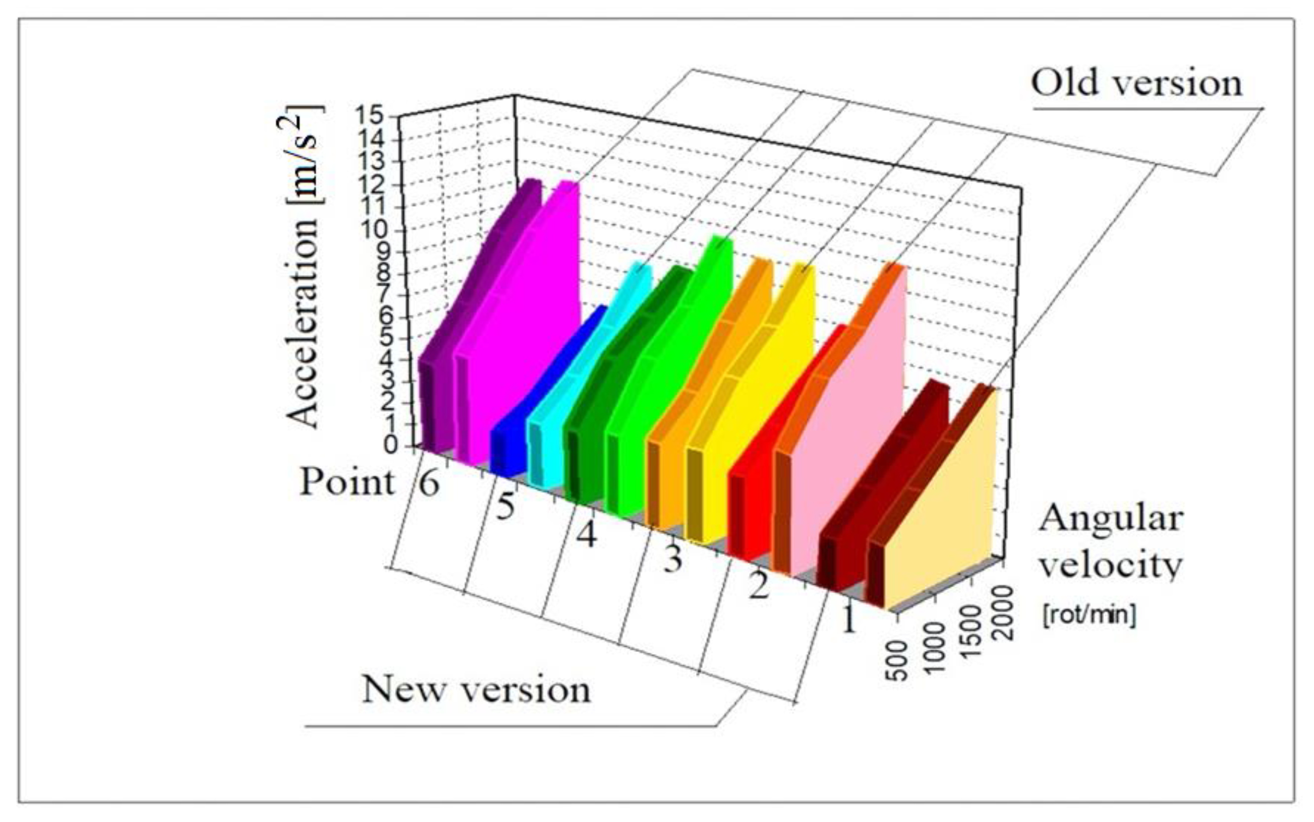
- The accelerations measured in the three points on the front surface of the new version adder box are approximately 20% lower than the accelerations measured on the front surface of the old version adder box.
- In the power take-off area, on the front surface of the two summing boxes, the measured accelerations have close values.
- The accelerations measured in the three points on the rear surface of the new variant adder box are approximately 30% lower than the accelerations measured on the rear surface of the old variant adder box.
- In the power take-off area, on the rear surface of the two adder boxes, the accelerations measured on the surface of the new version box are 25–30% lower than the accelerations measured on the surface of the old version adder box.
- In the measuring points in the power take-off area (points 3 and 6), there is a 25% decrease in accelerations on the adder box, the new variant at a speed of 1000 rpm.
- In Figure 38 are presented, in summary, the accelerations measured on the two summation and distribution boxes at the six measurement points at the four test regimes.
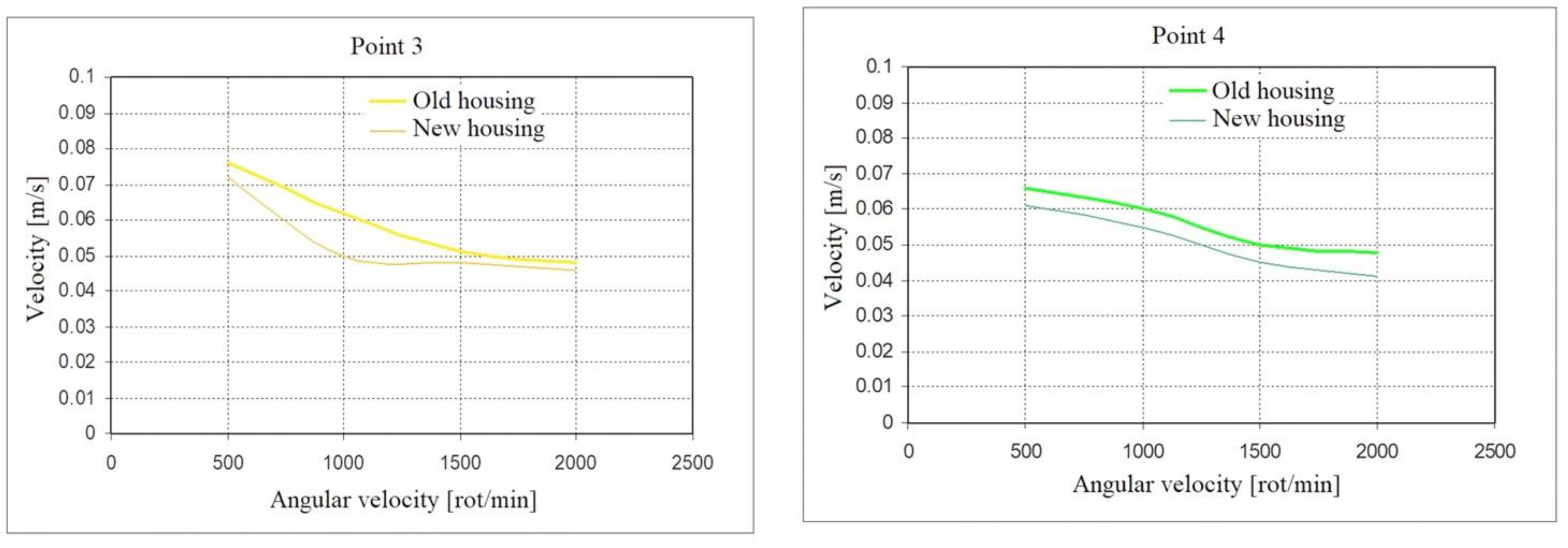
- Determining the speeds on the surfaces of the summing boxes
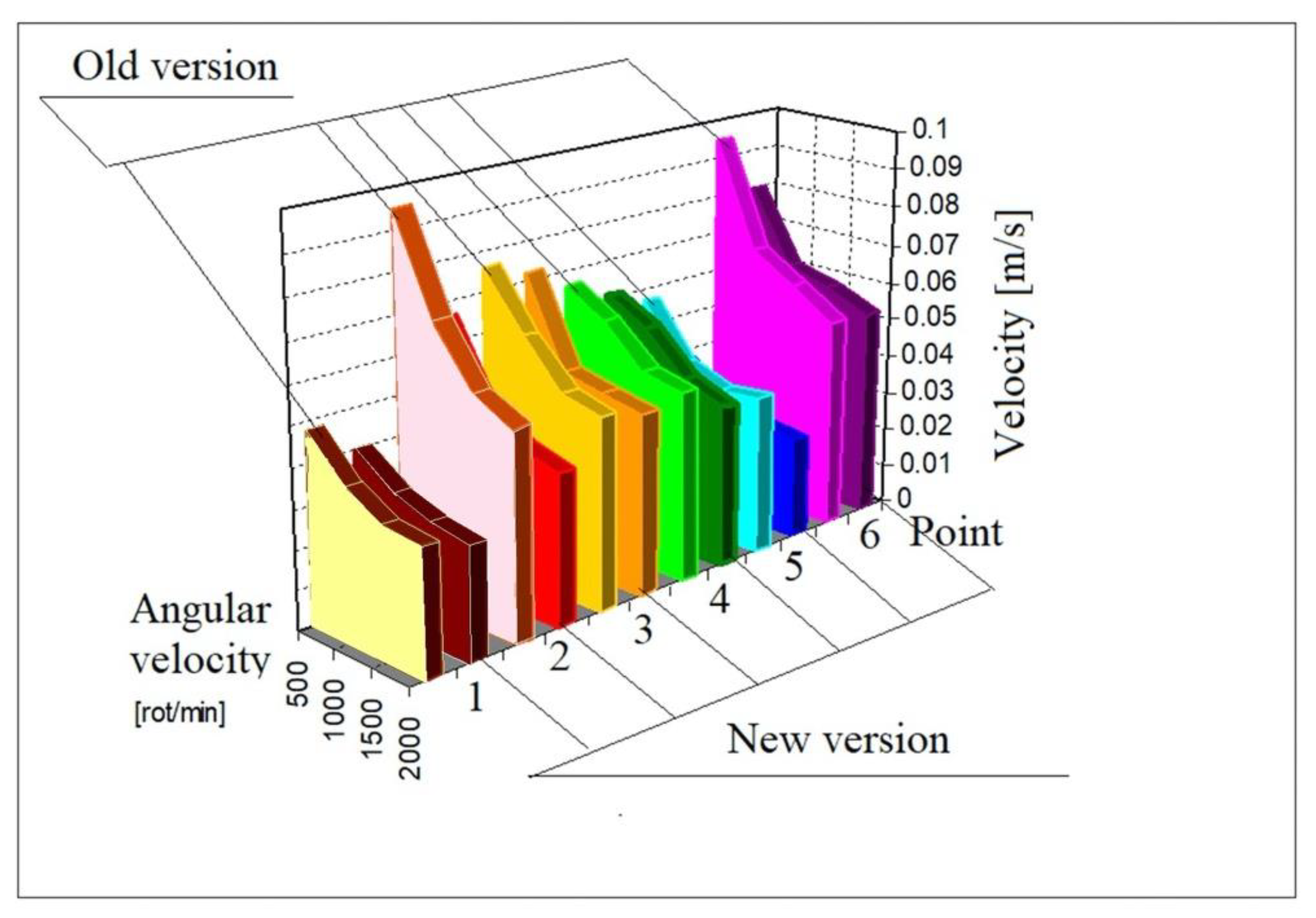
- The speeds determined in the three points on the front surface of the new version adder box are approximately 15% lower than the speeds determined for the old version adder box.
- In the power take-off area (point No. 3), on the front surface of the two adder boxes, the speeds measured on the new version adder box are 20% lower than the speeds measured on the old version adder box.
- The speeds measured in the three points on the rear surface of the new version adder box are on average 25% lower than the speeds measured on the rear surface of the old version adder box.
- In the area of the power take-off, on the back surface of the two adder boxes, the speeds measured on the surface of the new version box are 15–20% lower than the speeds measured on the surface of the old version adder box.
- At the measuring points in the power take-off area (points 3 and 6), a 15% decrease of the speeds on the summing box is observed, the new variant at speeds of 500 and 1000 rpm.
- In Figure 39 are presented, in summary, the speeds measured on the two summation boxes at the six measurement points at the four test regimes.
- At the measuring points in the area of the power take-off (points 3 and 6), a 15% decrease of the speeds on the summing box is observed, the new variant at speeds of 500 and 1000 rpm.
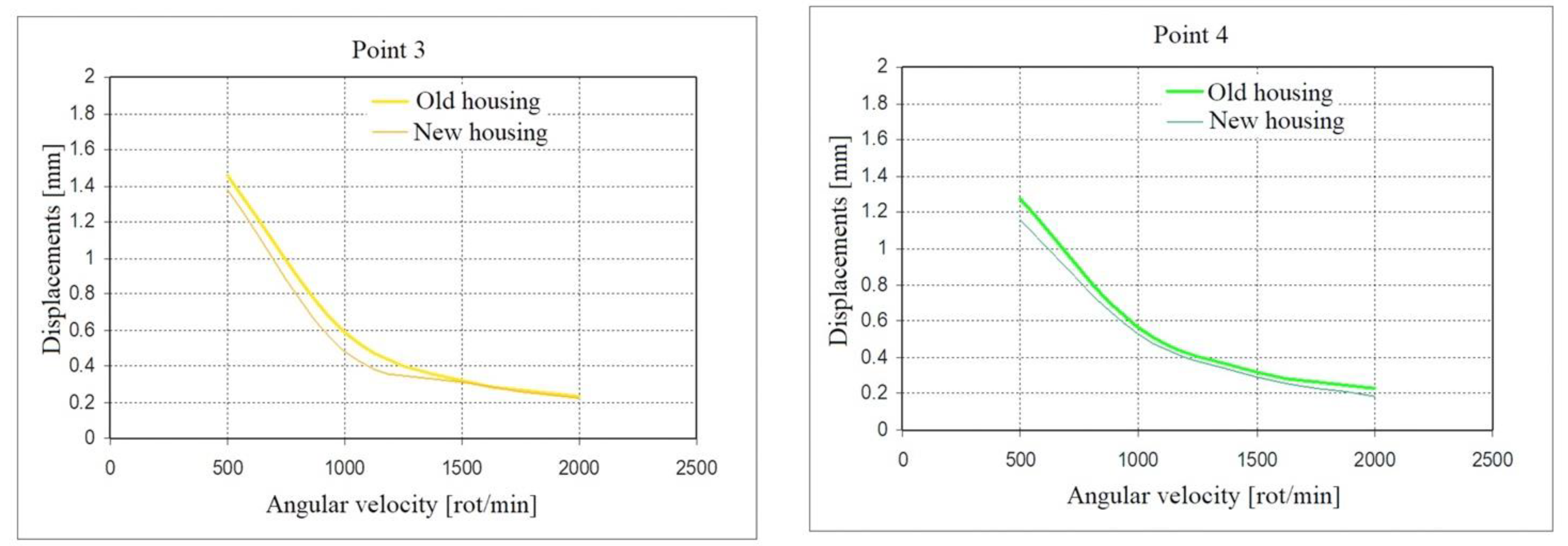
- Determining the displacements on the surfaces of the summing boxes
- The displacements measured in the three points on the front surface of the new variant adder box are approximately 15% smaller than the measured displacements on the front surface of the old variant adder box.
- In the power take-off area (point No. 3), on the front surface of the two adder boxes, the displacement measured on the adder box of the new version is 15% smaller than the displacement measured on the adder box of the old version.
- The displacements measured in the three points on the rear surface of the new variant adder box are on average 30% smaller than the displacements measured on the rear surface of the old variant adder box.
- In the area of the power take-off (point 6), on the back surface of the two adder boxes, the displacements measured on the surface of the new variant box are 30% smaller than the displacements measured on the surface of the old variant adder box.
- At the measuring points in the power take-off area (points 3 and 6), there is a 10% decrease in displacements on the adder box, the new variant at speeds of 500 and 1000 rpm.
- In Figure 40 are presented, in summary, the displacements measured on the two summation boxes at the six measurement points at the four test regimes.
- Measurement and experimental analysis of noise radiated by the surfaces of adder gearboxes
- (a)
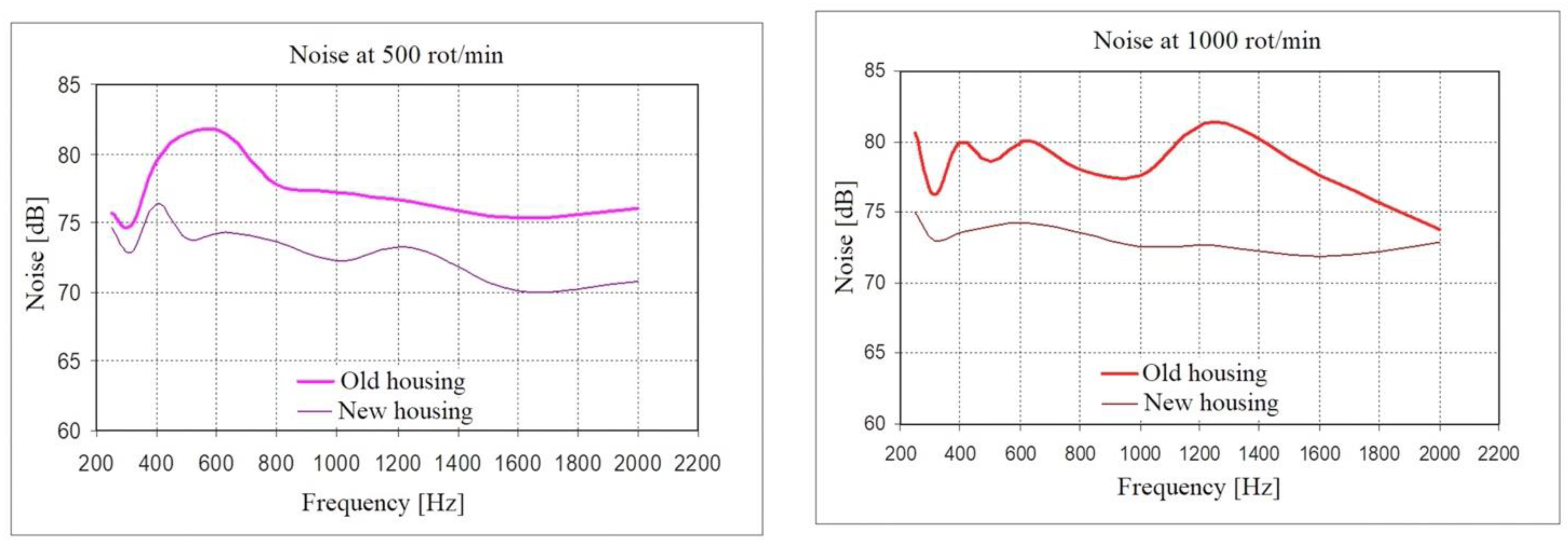
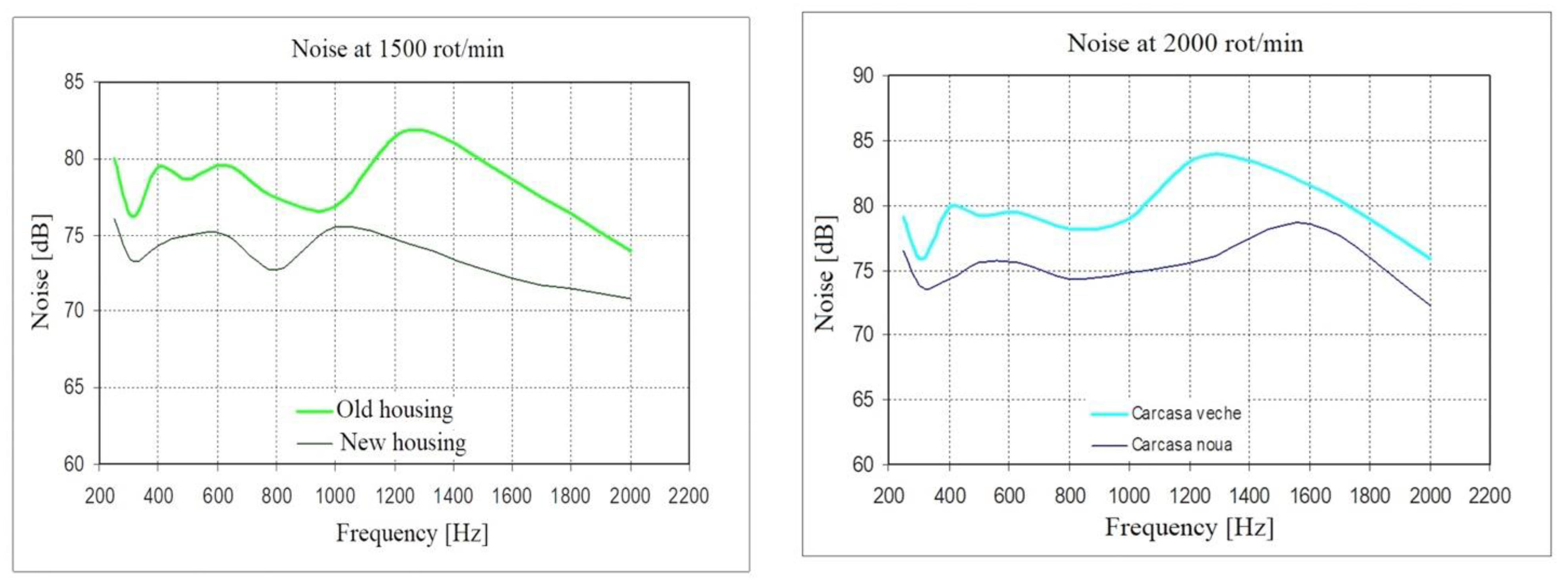
- Noise radiated from the front surface of the summing boxes:
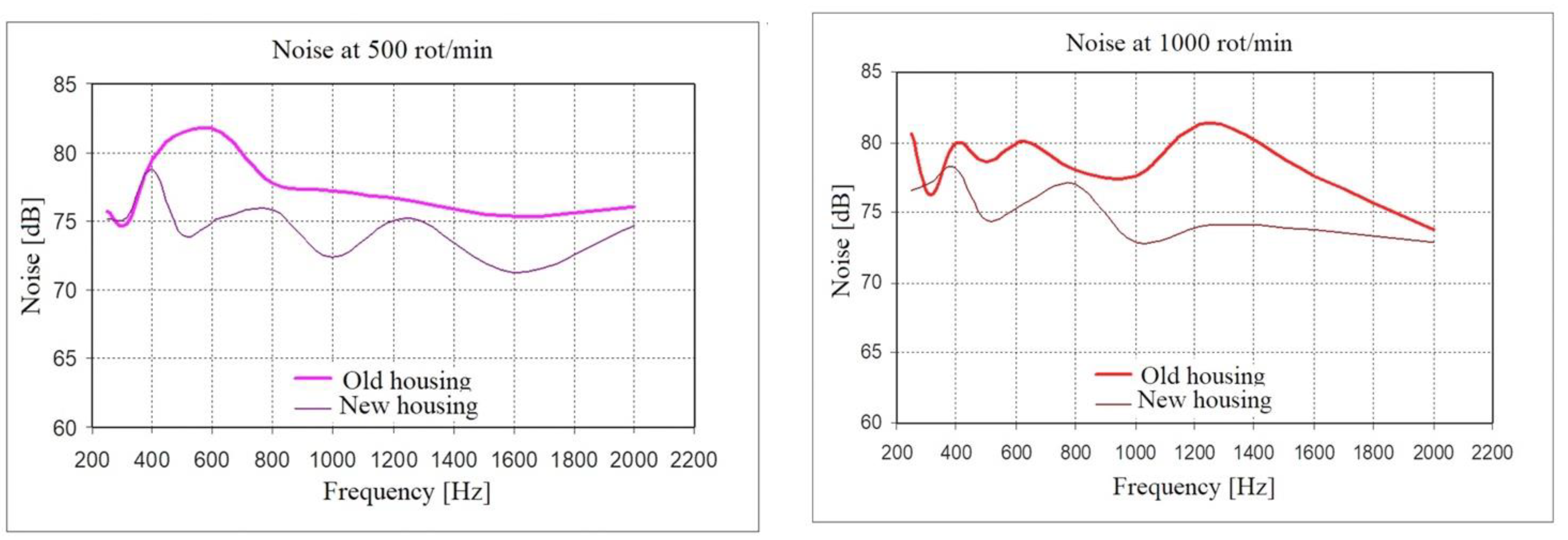
- At a speed of 500 rpm, for the dominant resonant frequencies of 395, 660, and 1600 Hz (determined in Section 5), the noise radiated by the new variant adder box decreased by 8% compared to the noise radiated by the old adder box.
- At the speed of 1000 rot/min, for the dominant resonant frequencies of 395 and 660 Hz, the noise radiated by the new variant adder box decreased by 10% compared to the noise radiated by the old adder box.
- At a speed of 1000 rpm, for the frequency of 1600 Hz, we notice a decrease of 6–7% in the noise radiated by the new version summing box.
- At a speed of 1000 rpm, for the new variant adder box, a constant noise level around 73 dB for the entire frequency range 30–2000 Hz is observed.
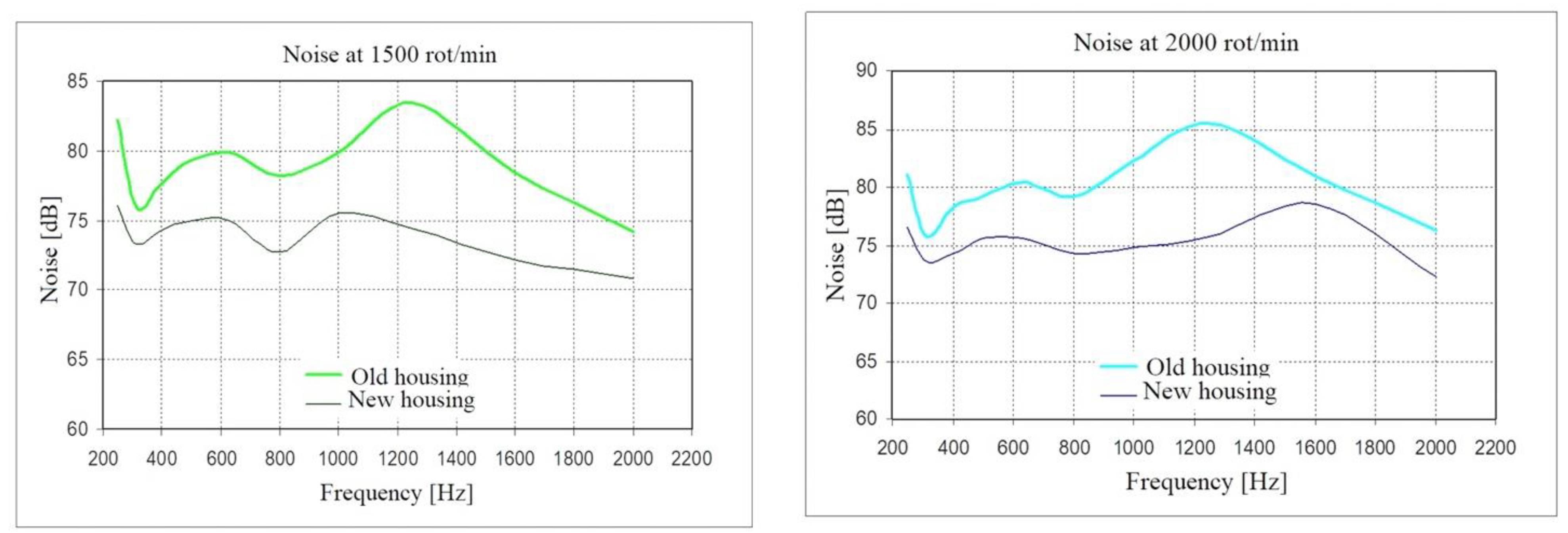
- At a speed of 1500 rot/min, for the dominant resonant frequencies of 395 and 660 Hz, the noise radiated by the new variant adder box decreased by 7% compared to the noise radiated by the old adder box.
- At the speed of 1500 rot/min, for the frequency of 1600 Hz, we observe a decrease of 9% of the noise radiated by the new version summing box.
- At a speed of 1500 rot/min, for the new variant adder box is observed a noise leveling around 72 dB for the whole frequency range 30–2000 Hz.
- At a speed of 2000 rpm, for the dominant resonant frequencies of 395, 660, and 1600 Hz, the noise radiated by the new variant box decreased by 6% compared to the noise radiated by the old sum box.
- At the speed of 2000 rot/min, for the new variant adder box is observed a constant of the noise level around 75 dB for the whole frequency range 30–2000 Hz.
- (b)
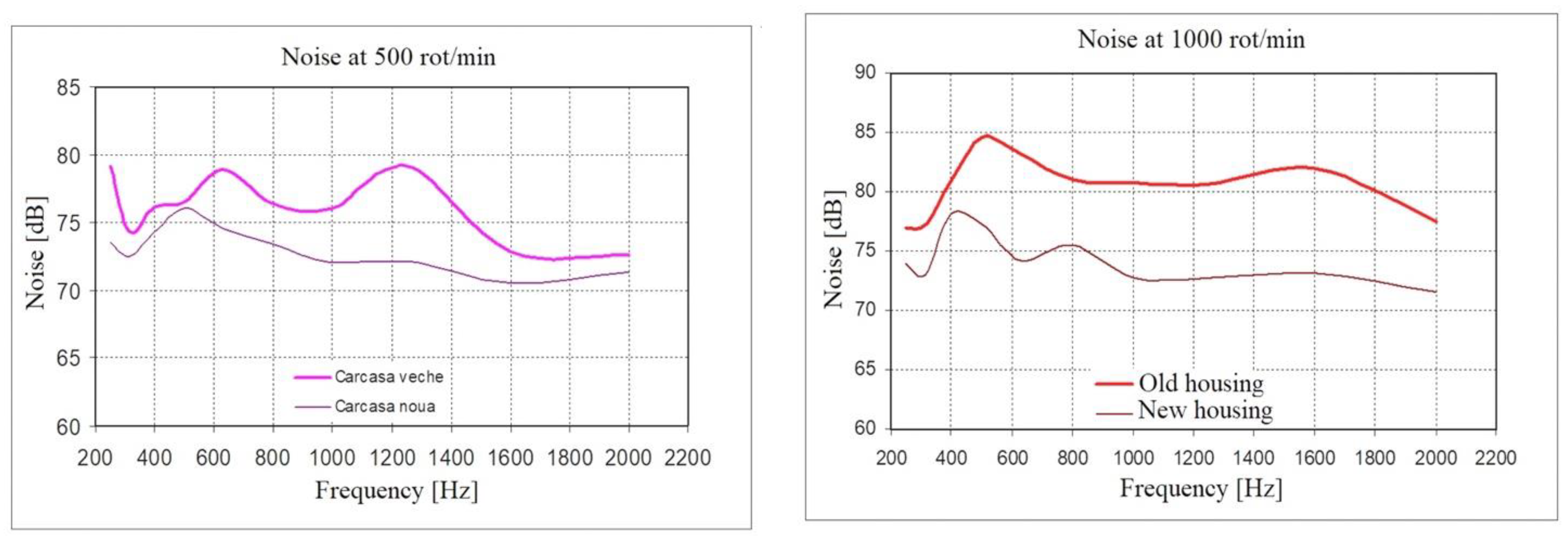
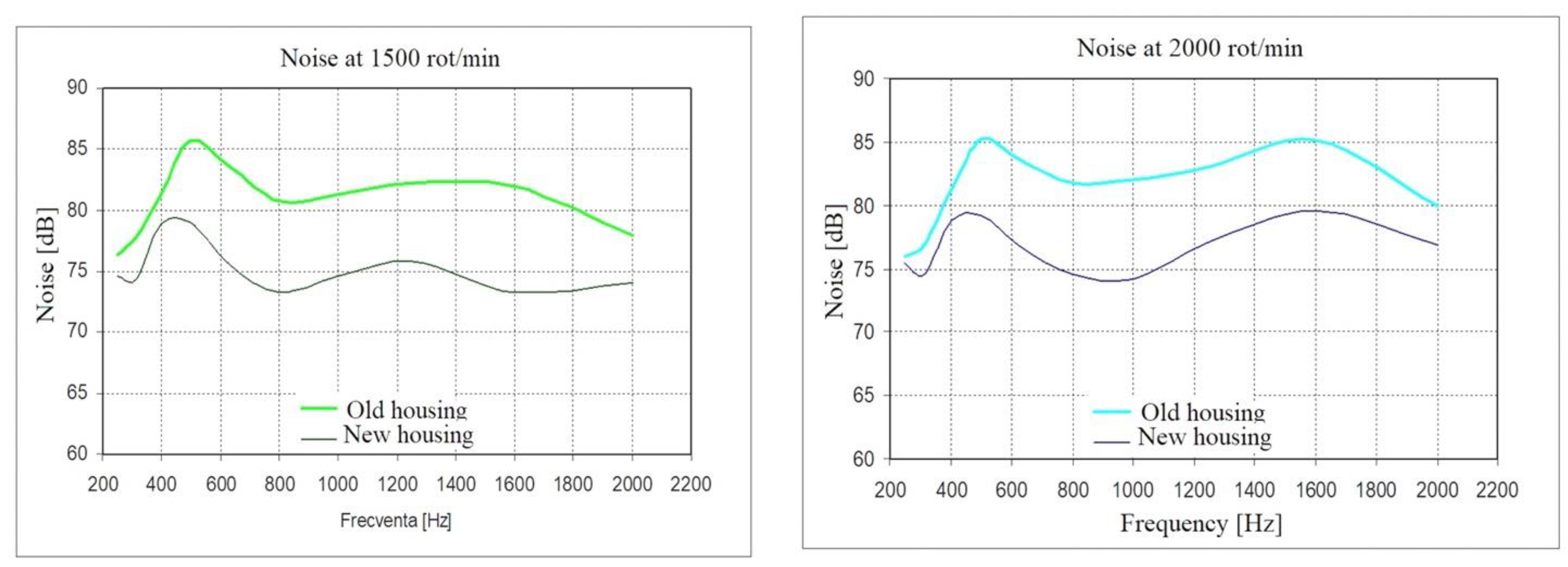
- Noise radiating from the rear surface of the summing boxes:
- At a speed of 500 rpm, for the dominant resonant frequencies of 395, 600, and 1550 Hz (determined in Section 5), the noise radiated by the new variant adder box decreased by 5% compared to the noise radiated by the old adder box.
- At a speed of 1000 rot/min, for the dominant resonant frequencies of 395 and 600 Hz, the noise radiated by the new version box decreased by 10% compared to the noise radiated by the old box.
- At a speed of 1000 rpm, for the frequency of 1550 Hz, we observe a decrease of 12% of the noise radiated by the new version summing box.
- At a speed of 1000 rpm, for the new variant adder box is observed a constancy of the noise level around 75 dB for the whole frequency range 30–2000 Hz.
- At a speed of 1500 rot/min, for the dominant resonant frequencies of 395, 600, and 1550 Hz, the noise radiated by the new variant adder box decreased by 9% compared to the noise radiated by the old adder box.
- At the speed of 1500 rot/min, for the frequency of 1600 Hz, we observe a decrease of 9% of the noise radiated by the new version summing box.
- At a speed of 1500 rot/min, for the new variant adder box is observed a noise leveling around 75 dB for the whole frequency range 30–2000 Hz.
- At the speed of 2000 rot min, for the dominant resonant frequencies of 395, 600, and 1550 Hz, the noise radiated by the new adder box decreased by 7% compared to the noise radiated by the old adder box.
- At the speed of 2000 rpm, for the new variant adder box, there is a constant noise level around 75 dB for the whole frequency range 30–2000 Hz with a slight increase to 80 dB around the frequency of 1600 Hz.
- (c)
- Noise radiated by the lateral surfaces of the summing boxes:
- For the whole range of speeds (500, 1000, 1500, and 2000 rpm) and the whole range of frequencies (30–2000 Hz), the noise radiated by the new variant adder box decreased by 7–10% compared to the noise radiated by the old adder box.
- For the new variant adder box, a noise level between 70 dB and 75 dB is observed for the whole frequency range 30–2000 Hz.
- Finally, by implementing the proposals for the constructive modification of the adder box, it can be stated that:
- By removing the large cover assembled by screws, inserting the rods, and reinforcing plates inside the housing, a new variant of the housing structure was stiffened, a proposed objective for reducing the structural noise of the housing.
- The vibration level of the structure and implicitly of the adder box as a whole was reduced.
- The noise produced by the adder box in the new version decreased, on average, by 10–15% compared to the noise produced by the adder box in the old version.
- A constancy was obtained within limited limits (70–75 dB) of the noise level produced by the new version adder box compared to the old version adder box.
- A simplification of the manufacturing technology was obtained and implicitly a reduction of the labor and of the assembly time of the adder box.
- A reduction of the mass of the adder box was obtained with the new variant by approximately 5%, in this phase being relatively little, but the experiments that will follow regarding the achievement of the future objectives of the thesis may achieve a significant reduction of the mass of the adder and distribution box ensemble.
8. Conclusions
- Analysis of the causes and noise sources of the summing gearboxes.
- Analysis of the noise transmission mechanism in the housing structure of the adder and distribution box.
- Structural and modal analysis of the gearbox housing with the finite element method.
- Experimental determination of the basic parameters of the vibration of the box structure of the summing box (resonant frequencies, amplitudes of vibration displacements of the structure surface, and their distribution on the analyzed surface).
- Analysis of the results of the experimental determinations and presentation of the solutions for modifying the case of the summing box.
- Comparative experimental determinations made by stand testing the adder box with the existing case and the adder box with the modified case.
- Analysis of the results of comparative experiments and validation of the changes made on the housing that led to the reduction of the structure noise and the improvement of the constructive solution.
- Measurement and experimental analysis of the noise radiated by the surfaces of the adder box housing in a state of simulated vibration for the same frequency range.
- Determining the resonant frequencies of the structure of the summing box to which correspond maximum values of the noise radiated by its surfaces.
- Experimental determination of the amplitudes of the vibration displacements of the surface of the summing box, their distribution on the analyzed surface, and the location of the areas that present maximum amplitudes.
- Establishing the program of comparative tests on the stand for both variants of summing boxes (the old version box equipped with the existing case and the new version box equipped with the modified case).
- Experimental determination on the stand of the vibration parameters of the old and new variant summing boxes for the running-in test (accelerations, speeds, and displacements in six points on the carcass surfaces).
- Experimental determination on the stand of the noise radiated by the surfaces of the old and new variant summing boxes at the running-in test (noise radiated by the surface of the front, rear, lateral left, and lateral right).
- Processing the recorded results and comparing them in order to validate the proposed solution for modifying the case of the summing box.
- Improving the system of fastening and fixing the chassis, improving the damping being an efficient and consistent procedure for reducing structural noise.
- Improving the lubrication system, where we have many components both inside and outside the adder box. A thorough study, supported by in-service behavior information, followed by improvement solutions, tests, and experiments, can reduce the structural noise of the box. It is possible to intervene and improve the fixing of the central ramp inside, the fixing of the inner and outer pipes, the fixing and drive of the pump, and the fixing of the filters on the housing.
- Similar to the lubrication system, a research direction can also be the oil cooling–heating system, taking into account that this adder box works in an environment with high temperature fluctuations.
- Improving gears and smooth operation of bearings, other powerful sources that generate structural noise. Basically, the transmission ratio can be kept for gears, but the module, the gear angle and the specific displacements, the surface quality, the lubrication quality, etc., can be improved.
Author Contributions
Funding
Institutional Review Board Statement
Informed Consent Statement
Data Availability Statement
Acknowledgments
Conflicts of Interest
Appendix A
| Measurement Point | Angular Speed [rot/min] | Acceleration [m/s2] | Decreasing/Increasing [%] | |
|---|---|---|---|---|
| CSD Old | CSD New | |||
| 1 | 500 | 2.5 | 2.1 | 19.04 ↓ |
| 1000 | 4 | 3.5 | 14.28 ↓ | |
| 1500 | 5.3 | 5 | 6 ↓ | |
| 2000 | 7 | 6.6 | 6.06 ↓ | |
| 2 | 500 | 5 | 3.5 | 42.85 ↓ |
| 1000 | 7.5 | 5 | 50 ↓ | |
| 1500 | 9 | 6.5 | 38.46 ↓ | |
| 2000 | 11 | 8 | 37.5 ↓ | |
| 3 | 500 | 4 | 3.8 | 5.26 ↓ |
| 1000 | 6.5 | 5.3 | 22.64 ↓ | |
| 1500 | 8.1 | 7.8 | 3.84 ↓ | |
| 2000 | 10.2 | 10 | 2 ↓ | |
| 4 | 500 | 3.5 | 3.2 | 9.37 ↓ |
| 1000 | 6.3 | 5.8 | 8.62 ↓ | |
| 1500 | 8 | 7.2 | 11.11 ↓ | |
| 2000 | 10.5 | 8.7 | 20.68 ↓ | |
| 5 | 500 | 3 | 2 | 50 ↓ |
| 1000 | 4.5 | 3.1 | 45.16 ↓ | |
| 1500 | 6.2 | 4.7 | 31.91 ↓ | |
| 2000 | 8.5 | 6.1 | 39.34 ↓ | |
| 6 | 500 | 5 | 4.2 | 19.04 ↓ |
| 1000 | 7.2 | 6.4 | 12.5 ↓ | |
| 1500 | 9.7 | 9.3 | 4.3 ↓ | |
| 2000 | 11.5 | 11.2 | 2.67 ↓ | |
| Measurement Point | Angular Velocity [rot/min] | Velocity [m/s] | Decreasing/Increasing [%] | |
|---|---|---|---|---|
| CSD Old | CSD New | |||
| 1 | 500 | 0.048 | 0.040 | 20 ↓ |
| 1000 | 0.038 | 0.033 | 15.15 ↓ | |
| 1500 | 0.033 | 0.030 | 10 ↓ | |
| 2000 | 0.032 | 0.028 | 14.28 ↓ | |
| 2 | 500 | 0.095 | 0.066 | 43.93 ↓ |
| 1000 | 0.071 | 0.047 | 51.06 ↓ | |
| 1500 | 0.057 | 0.041 | 39.02 ↓ | |
| 2000 | 0.052 | 0.038 | 36.84 ↓ | |
| 3 | 500 | 0.076 | 0.072 | 5.55 ↓ |
| 1000 | 0.062 | 0.050 | 24 ↓ | |
| 1500 | 0.051 | 0.048 | 6.25 ↓ | |
| 2000 | 0.048 | 0.046 | 4.34 ↓ | |
| 4 | 500 | 0.066 | 0.061 | 8.19 ↓ |
| 1000 | 0.060 | 0.055 | 9.09 ↓ | |
| 1500 | 0.050 | 0.045 | 11.11 ↓ | |
| 2000 | 0.048 | 0.041 | 17.07 ↓ | |
| 5 | 500 | 0.057 | 0.038 | 50 ↓ |
| 1000 | 0.043 | 0.029 | 48.27 ↓ | |
| 1500 | 0.039 | 0.027 | 44.44 ↓ | |
| 2000 | 0.040 | 0.026 | 53.84 ↓ | |
| 6 | 500 | 0.095 | 0.080 | 18.75 ↓ |
| 1000 | 0.068 | 0.061 | 11.47 ↓ | |
| 1500 | 0.061 | 0.058 | 5.17 ↓ | |
| 2000 | 0.054 | 0.053 | 1.88 ↓ | |
| Measurement Point | Angular Velocity [rot/min] | Displacement [mm] | Decreasing/Increasing [%] | |
|---|---|---|---|---|
| Old Box | New Box | |||
| 1 | 500 | 0.91 | 0.76 | 19.73 ↓ |
| 1000 | 0.36 | 0.32 | 12.5 ↓ | |
| 1500 | 0.21 | 0.20 | 5 ↓ | |
| 2000 | 0.15 | 0.15 | 0 ↓ | |
| 2 | 500 | 1.46 | 1.27 | 14.96 ↓ |
| 1000 | 0.59 | 0.45 | 31.11 ↓ | |
| 1500 | 0.36 | 0.26 | 38.46 ↓ | |
| 2000 | 0.25 | 0.18 | 38.88 ↓ | |
| 3 | 500 | 1.46 | 1.38 | 5.79 ↓ |
| 1000 | 0.59 | 0.48 | 22.91 ↓ | |
| 1500 | 0.32 | 0.31 | 3.22 ↓ | |
| 2000 | 0.23 | 0.22 | 4.5 ↓ | |
| 4 | 500 | 1.27 | 1.16 | 9.48 ↓ |
| 1000 | 0.57 | 0.53 | 7.54 ↓ | |
| 1500 | 0.32 | 0.29 | 10.34 ↓ | |
| 2000 | 0.23 | 0.19 | 21.05 ↓ | |
| 5 | 500 | 1.09 | 0.73 | 49.31 ↓ |
| 1000 | 0.41 | 0.28 | 46.42 ↓ | |
| 1500 | 0.25 | 0.19 | 31.57 ↓ | |
| 2000 | 0.19 | 0.14 | 35.71 ↓ | |
| 6 | 500 | 1.82 | 1.53 | 18.95 ↓ |
| 1000 | 0.65 | 0.58 | 12.06 ↓ | |
| 1500 | 0.39 | 0.37 | 5.4 ↓ | |
| 2000 | 0.26 | 0.25 | 4 ↓ | |
| Frequency [Hz] | Angular Velocity [rot/min] | CSD Old Noise [dB] | CSD New Noise [dB] | Decreasing/Increasing Noise Level [%] |
|---|---|---|---|---|
| 250 | 500 | 75.7 | 74.7 | 1.33 ↓ |
| 1000 | 80.6 | 75 | 7.46 ↓ | |
| 1500 | 80 | 76.1 | 5.12 ↓ | |
| 2000 | 79 | 76.5 | 3.26 ↓ | |
| 315 | 500 | 74.8 | 72.8 | 2.74 ↓ |
| 1000 | 76.2 | 73 | 4.38 ↓ | |
| 1500 | 76.2 | 73.3 | 3.95 ↓ | |
| 2000 | 75.8 | 73.6 | 2.98 ↓ | |
| 400 | 500 | 79.5 | 76.4 | 4.05 ↓ |
| 1000 | 79.9 | 73.6 | 8.55 ↓ | |
| 1500 | 79.4 | 74.3 | 6.86 ↓ | |
| 2000 | 79.8 | 74.3 | 7.40 ↓ | |
| 500 | 500 | 81.5 | 73.9 | 10.28 ↓ |
| 1000 | 78.6 | 74 | 6.21 ↓ | |
| 1500 | 78.6 | 74.9 | 4.93 ↓ | |
| 2000 | 79.2 | 75.6 | 4.76 ↓ | |
| 630 | 500 | 81.4 | 74.3 | 9.55 ↓ |
| 1000 | 80.1 | 74.2 | 7.95 ↓ | |
| 1500 | 79.5 | 74.9 | 6.14 ↓ | |
| 2000 | 79.5 | 75.6 | 5.15 ↓ | |
| 800 | 500 | 77.8 | 73.7 | 5.56 ↓ |
| 1000 | 78 | 73.6 | 5.97 ↓ | |
| 1500 | 77.4 | 72.7 | 6.46 ↓ | |
| 2000 | 78.1 | 74.3 | 5.11 ↓ | |
| 1000 | 500 | 77.2 | 72.3 | 6.77 ↓ |
| 1000 | 77.6 | 72.6 | 6.88 ↓ | |
| 1500 | 76.9 | 75.5 | 1.85 ↓ | |
| 2000 | 78.9 | 74.8 | 5.48 ↓ | |
| 1250 | 500 | 76.5 | 73.2 | 4.50 ↓ |
| 1000 | 81.4 | 72.7 | 11.96 ↓ | |
| 1500 | 81.9 | 74.4 | 10.08 ↓ | |
| 2000 | 83.8 | 75.8 | 10.55 ↓ | |
| 1600 | 500 | 75.4 | 70.1 | 7.56 ↓ |
| 1000 | 77.6 | 71.9 | 7.92 ↓ | |
| 1500 | 78.6 | 72.2 | 8.86 ↓ | |
| 2000 | 81.5 | 78.5 | 3.82 ↓ | |
| 2000 | 500 | 76.1 | 70.8 | 7.48 ↓ |
| 1000 | 73.8 | 72.9 | 1.23 ↓ | |
| 1500 | 73.9 | 70.8 | 4.37 ↓ | |
| 2000 | 75.8 | 72.2 | 4.98 ↓ |
| Frequency [Hz] | Angular Velocity [rot/min] | CSD Old Noise [dB] | CSD New Noise [dB] | Decreasing/Increasing Noise Level [%] |
|---|---|---|---|---|
| 250 | 500 | 79.2 | 73.5 | 7.75 ↓ |
| 1000 | 77 | 73.9 | 4.19 ↓ | |
| 1500 | 76.3 | 74.6 | 2.28 ↓ | |
| 2000 | 76 | 75.4 | 0.79 ↓ | |
| 315 | 500 | 74.3 | 72.5 | 2.48 ↓ |
| 1000 | 77.3 | 73 | 5.89 ↓ | |
| 1500 | 77.8 | 74.3 | 4.71 ↓ | |
| 2000 | 76.9 | 74.5 | 3.22 ↓ | |
| 400 | 500 | 76.2 | 74.3 | 2.55 ↓ |
| 1000 | 80.9 | 78.1 | 3.58 ↓ | |
| 1500 | 81.3 | 78.9 | 3.04 ↓ | |
| 2000 | 81.2 | 78.8 | 3.04 ↓ | |
| 500 | 500 | 76.5 | 76 | 0.65 ↓ |
| 1000 | 84.6 | 77.3 | 9.44 ↓ | |
| 1500 | 85.7 | 79 | 8.48 ↓ | |
| 2000 | 85.3 | 79.2 | 7.70 ↓ | |
| 630 | 500 | 78.9 | 74.6 | 5.76 ↓ |
| 1000 | 83.1 | 74.2 | 11.99 ↓ | |
| 1500 | 83.6 | 75.5 | 10.72 ↓ | |
| 2000 | 83.5 | 76.8 | 8.72 ↓ | |
| 800 | 500 | 76.4 | 73.4 | 4.08 ↓ |
| 1000 | 81 | 75.5 | 7.28 ↓ | |
| 1500 | 80.8 | 73.2 | 10.38 ↓ | |
| 2000 | 81.7 | 74.6 | 9.51 ↓ | |
| 1000 | 500 | 76 | 72 | 5.55 ↓ |
| 1000 | 80.8 | 72.8 | 10.98 ↓ | |
| 1500 | 81.3 | 74.6 | 8.98 ↓ | |
| 2000 | 82 | 74.2 | 10.51 ↓ | |
| 1250 | 500 | 79.1 | 72.2 | 9.55 ↓ |
| 1000 | 80.6 | 72.8 | 10.71 ↓ | |
| 1500 | 82.2 | 75.8 | 8.44 ↓ | |
| 2000 | 83.1 | 77.1 | 7.78 ↓ | |
| 1600 | 500 | 72.8 | 70.5 | 3.26 ↓ |
| 1000 | 82 | 73.1 | 12.17 ↓ | |
| 1500 | 82 | 73.3 | 11.86 ↓ | |
| 2000 | 85.1 | 79.6 | 6.90 ↓ | |
| 2000 | 500 | 72.6 | 71.3 | 1.82 ↓ |
| 1000 | 77.5 | 71.6 | 8.24 ↓ | |
| 1500 | 77.9 | 74 | 5.27 ↓ | |
| 2000 | 80 | 76.9 | 4.03 ↓ |
| Frequency [Hz] | Angular Velocity [rot/min] | CSD Old Noise [dB] | CSD New Noise [dB] | Decreasing/Increasing Noise Level [%] |
|---|---|---|---|---|
| 250 | 500 | 79.2 | 74.7 | 6.02 ↓ |
| 1000 | 77 | 75 | 2.66 ↓ | |
| 1500 | 82.2 | 76.1 | 8.01 ↓ | |
| 2000 | 81.1 | 76.5 | 6.01 ↓ | |
| 315 | 500 | 74.3 | 72.8 | 2.06 ↓ |
| 1000 | 77.3 | 73 | 5.89 ↓ | |
| 1500 | 76 | 73.3 | 3.68 ↓ | |
| 2000 | 75.7 | 73.6 | 2.85 ↓ | |
| 400 | 500 | 76.2 | 75.1 | 1.46 ↓ |
| 1000 | 80.9 | 73.6 | 9.91 ↓ | |
| 1500 | 77.6 | 74.3 | 4.44 ↓ | |
| 2000 | 78.2 | 74.3 | 5.24 ↓ | |
| 500 | 500 | 76.1 | 73.9 | 2.97 ↓ |
| 1000 | 84.6 | 74 | 14.32 ↓ | |
| 1500 | 79.3 | 74.9 | 5.87 ↓ | |
| 2000 | 79.2 | 75.6 | 4.76 ↓ | |
| 630 | 500 | 78.9 | 74.3 | 6.19 ↓ |
| 1000 | 83.1 | 74.2 | 11.99 ↓ | |
| 1500 | 79.9 | 74.9 | 6.67 ↓ | |
| 2000 | 80.4 | 75.6 | 6.34 ↓ | |
| 800 | 500 | 76.4 | 73.7 | 3.66 ↓ |
| 1000 | 81 | 73.6 | 10.05 ↓ | |
| 1500 | 78.2 | 72.7 | 7.56 ↓ | |
| 2000 | 79.2 | 74.3 | 6.59 ↓ | |
| 1000 | 500 | 76 | 72.3 | 5.11 ↓ |
| 1000 | 80.8 | 72.6 | 11.29 ↓ | |
| 1500 | 79.9 | 75.5 | 5.82 ↓ | |
| 2000 | 82.2 | 74.8 | 9.89 ↓ | |
| 1250 | 500 | 79.1 | 73.2 | 8.06 ↓ |
| 1000 | 80.6 | 72.7 | 10.86 ↓ | |
| 1500 | 83.4 | 74.4 | 12.09 ↓ | |
| 2000 | 85.5 | 75.8 | 12.79 ↓ | |
| 1600 | 500 | 72.8 | 70.1 | 3.85 ↓ |
| 1000 | 82 | 71.9 | 14.04 ↓ | |
| 1500 | 78.4 | 72.2 | 8.58 ↓ | |
| 2000 | 81 | 78.5 | 3.18 ↓ | |
| 2000 | 500 | 72.6 | 70.8 | 2.54 ↓ |
| 1000 | 77.5 | 72.9 | 6.31 ↓ | |
| 1500 | 74.2 | 70.8 | 4.80 ↓ | |
| 2000 | 76.3 | 72.2 | 5.67 ↓ |
| Frequency [Hz] | Angular Velocity [rot/min.] | CSD Old Noise [dB] | CSD New Noise [dB] | Decreasing/Increasing Noise Level [%] |
|---|---|---|---|---|
| 250 | 500 | 75.7 | 75.1 | 0.79 ↓ |
| 1000 | 80.6 | 76.6 | 5.22 ↓ | |
| 1500 | 80 | 75.9 | 5.40 ↓ | |
| 2000 | 79 | 76.8 | 2.86 ↓ | |
| 315 | 500 | 74.8 | 75.3 | 0.66 ↓ |
| 1000 | 76.2 | 77.1 | 1.18 ↓ | |
| 1500 | 76.2 | 76.8 | 0.78 ↓ | |
| 2000 | 75.8 | 75.2 | 0.79 ↓ | |
| 400 | 500 | 79.5 | 78.8 | 0.88 ↓ |
| 1000 | 79.9 | 78.2 | 2.17 ↓ | |
| 1500 | 79.4 | 78.8 | 0.76 ↓ | |
| 2000 | 79.8 | 79.2 | 0.75 ↓ | |
| 500 | 500 | 81.5 | 74 | 10.13 ↓ |
| 1000 | 78.6 | 74.5 | 5.50 ↓ | |
| 1500 | 78.6 | 76 | 3.42 ↓ | |
| 2000 | 79.2 | 77.5 | 2.19 ↓ | |
| 630 | 500 | 81.4 | 75.2 | 8.24 ↓ |
| 1000 | 80.1 | 75.7 | 5.81 ↓ | |
| 1500 | 79.5 | 77.1 | 3.11 ↓ | |
| 2000 | 79.5 | 78.2 | 1.66 ↓ | |
| 800 | 500 | 77.8 | 75.8 | 2.63 ↓ |
| 1000 | 78 | 77 | 1.29 ↓ | |
| 1500 | 77.4 | 74.2 | 4.31 ↓ | |
| 2000 | 78.1 | 77.5 | 0.77 ↓ | |
| 1000 | 500 | 77.2 | 72.4 | 6.62 ↓ |
| 1000 | 77.6 | 72.9 | 6.44 ↓ | |
| 1500 | 76.9 | 73.7 | 4.34 ↓ | |
| 2000 | 78.9 | 75.5 | 4.50 ↓ | |
| 1250 | 500 | 76.5 | 75.3 | 1.59 ↓ |
| 1000 | 81.4 | 74.1 | 9.85 ↓ | |
| 1500 | 81.9 | 74.8 | 9.49 ↓ | |
| 2000 | 83.8 | 76.5 | 9.54 ↓ | |
| 1600 | 500 | 75.4 | 71.2 | 5.89 ↓ |
| 1000 | 77.6 | 73.8 | 5.14 ↓ | |
| 1500 | 78.6 | 73.9 | 6.35 ↓ | |
| 2000 | 81.5 | 74.5 | 9.39 ↓ | |
| 2000 | 500 | 76.1 | 74.7 | 1.87 ↓ |
| 1000 | 73.8 | 72.9 | 1.23 ↓ | |
| 1500 | 73.9 | 73.8 | 0.13 ↓ | |
| 2000 | 75.8 | 74.8 | 1.33 ↓ |
References
- Soami, P. Modeling Vibration and Noise in a Gearbox. Mech. Eng. 2018, 140, 22–24. [Google Scholar]
- Furch, J.; Tran, C.V. Dynamics simulation of mechanical gearbox vibration. In Proceedings of the 10th International Scientific Conference on Aeronautics, Automotive and Railway Engineering and Technologies (BulTrans), Sozopol, Bulgaria, 15–17 September 2018; Volume 234. AR 02002. [Google Scholar] [CrossRef]
- Elisabeth, K.; John, L.; Lars, H.; Magnus, K.; Jing, L. Vibration-based Condition Monitoring of Heavy Duty Machine Driveline Parts: Torque Converter, Gearbox, Axles and Bearings. Int. J. Progn. Health Manag. 2019, 10. [Google Scholar] [CrossRef]
- Wu, H.; Wu, P.B.; Xu, K.; Li, J.C.; Li, F.S. Research on Vibration Characteristics and Stress Analysis of Gearbox Housing in High-Speed Trains. IEEE Access 2019, 7, 102508–102518. [Google Scholar] [CrossRef]
- Batizi, V.; Likhachev, D. Mass-geometric parameters improvement of gearbox by using vibration analysis. In Proceedings of the 14th International Conference on Vibration Engineering and Technology of Machinery (VETOMAC XIV), Lisbon, Portugal, 10–13 September 2018; Volume 211. AR 06002. [Google Scholar] [CrossRef]
- Guo, W.; Chen, C.; Xiao, N.C. Dynamic vibration feature analyses for a two-stage planetary gearbox with a varying crack using a rigid-flexible coupled model. J. Intell. Fuzzy Syst. 2018, 34, 3869–3880. [Google Scholar] [CrossRef]
- Furch, J.; Glos, J.; Nguyen, T.T. Modelling and Simulation of Mechanical Gearbox Vibrations. In Proceedings of the International Conference 20th International Scientific Conference on Transport Means, Juodkrante, Lithuania, 5–7 October 2016; pp. 133–139. [Google Scholar]
- Kucukay, F.; Pfeiffer, F. Clattering Vibrations in Gearboxes of Motor-Vehicles. Ingineur Arch. 1986, 56, 25–37. [Google Scholar] [CrossRef]
- Astridge, D.G. Gearbox Noise and Vibration- Review of Opportunities for Improving Safety and Reliability. In Proceedings of the Institution of Mechanical Engineers Series. 1st International Conf on Gearbox Noise and Vibration, Univ. Cambridge, Cambridge, UK, 9–11 April 1990; pp. 11–18. [Google Scholar]
- Vlase, S. A Method of Eliminating Lagrangian-Multipliersa from the Equation of Motion of Interconnected Mechanical Systems. J. Appl. Mech. Trans. ASME 1987, 54, 235–237. [Google Scholar] [CrossRef]
- Vlase, S.; Teodorescu, P.P. Elasto-Dynamics of a Solid with a General "Rigid" Motion using FEM Model Part I. Theoretical Approach. Rom. J. Phys. 2013, 58, 872–881. [Google Scholar]
- Scutaru, M.L.; Vlase, S.; Marin, M.; Modrea, A. New analytical method based on dynamic response of planar mechanical elastic systems. Bound. Value Probl. 2020, 2020, 104. [Google Scholar] [CrossRef]
- Wang, Q.; Shen, R.Y. Study on Vibration & Noise of Gearbox. In Proceedings of the 14th International Congress on Acoustics (ICA 14), Beijing, China, 3–10 September 1992; Volumes 1–4. pp. 679–680. [Google Scholar]
- Tuma, J. Analysis of Gearbox Vibration in Time Domain. In Proceedings of the Institute of Acoustics, Euro Noise 92, London, UK, 14–18 September 1992; Volume 14, pp. 597–604. [Google Scholar]
- Choy, F.K.; Ruan, Y.F.; Tu, Y.K.; Zakrajsek, J.J.; Townsend, D.P. Modal-Analysis of Multistage Gear Systems Coupled with Gearbox Vibration. J. Mech. Des. 1992, 114, 486–497. [Google Scholar] [CrossRef]
- Sargeant, M.; Stone, B.J. Coupled torsional and transverse vibration of gearboxes. In Proceedings of the 3rd International Symposium on Multi-Body Dynamics -Monitoring and Simulation Techniques, Loughborough, UK, 12–13 July 2004; pp. 299–309. [Google Scholar]
- Guan, Y.H.; Shepard, W.S.; Lim, T.C.; Li, M. Experimental analysis of an active vibration control system for gearboxes. Smart Mater. Struct. 2004, 13, 1230–1237. [Google Scholar] [CrossRef]
- Guan, Y.H.; Lim, T.C.; Shepard, W.S. Experimental study on active vibration control of a gearbox system. J. Sound Vib. 2005, 282, 713–733. [Google Scholar] [CrossRef]
- Li, M.F.; Lim, T.C.; Shepard, W.S.; Guan, Y.H. Experimental active vibration control of gear mesh harmonics in a power recirculation gearbox system using a piezoelectric stack actuator. Smart Mater. Struct. 2005, 14, 917–927. [Google Scholar] [CrossRef]
- Ploger, D.; Zech, P.; Rinderknecht, S. Experimental identification of high-frequency gear mesh vibrations in a planetary gearbox. In Proceedings of the International Conference on Noise and Vibration Engineering (ISMA)/International Conference on Uncertainty in Structural Dynamics (USD), Leuven, Belgium, 19–21 September 2016; pp. 911–924. [Google Scholar]





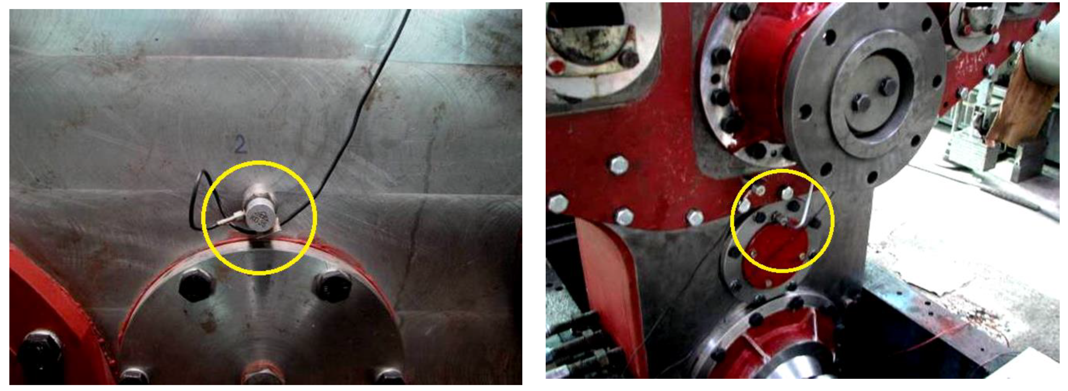








| Front Surface of the Housing | ||
|---|---|---|
| Point No. 1 | Point No. 2 | Point No. 3 |
| (500, 1200) mm | (1200, 1200) mm | (850, 600) mm |
| Rear Surface of the Housing | ||
| Point No. 4 | Point No. 5 | Point No. 6 |
| (1200, 1200) mm | (500, 1200) mm | (850, 600) mm |
| Frequency Areas (Hz) | |||||||
|---|---|---|---|---|---|---|---|
| 100–500 | 500–1000 | 1000–1500 | 1500–2000 | ||||
| No. Mode | Frequency | No. Mode | Frequency | No. Mode | Frequency | No. Mode | Frequency |
| 1 | 135 | 14 | 611 | 39 | 1019 | 76 | 1525 |
| 3 | 249 | 18 | 653 | 42 | 1063 | 79 | 1607 |
| 5 | 305 | 21 | 716 | 45 | 1126 | 82 | 1659 |
| 6 | 361 | 22 | 778 | 48 | 1150 | 85 | 1701 |
| 7 | 380 | 24 | 800 | 52 | 1200 | 88 | 1737 |
| 9 | 490 | 28 | 847 | 56 | 1244 | 91 | 1805 |
| 33 | 904 | 60 | 1300 | 94 | 1834 | ||
| 35 | 959 | 65 | 1355 | 97 | 1896 | ||
| 38 | 1000 | 68 | 1412 | 98 | 1901 | ||
| 70 | 1453 | 102 | 1936 | ||||
| 74 | 1498 | 103 | 1976 | ||||
| 104 | 1980 | ||||||
| 105 | 1984 | ||||||
| Frequency (Hz) | Displacements Amplitude Y (mm) | ||
|---|---|---|---|
| Point No.4 | Point No.5 | Point No.6 | |
| 395 | 0.55–0.75 | 0.60–0.70 | 0.85–0.95 |
| 1550 | 0.45–0.55 | 0.35–0.45 | 0.50–0.65 |
| Frequency [Hz] | Displacements Amplitude Y [mm] | ||
|---|---|---|---|
| Point No. 1 | Point No.2 | Point No.3 | |
| 395 | 0.40–0.55 | 0.45–0.65 | 0.55–0.70 |
| 1550 | 0.25–0.40 | 0.30–0.40 | 0.45–0.55 |
| Frequency | Measurement Point | Displacements Amplitude (mm) | |
|---|---|---|---|
| Simulation | Measurement | ||
| 395 | 1 | 0.578 | 0.40–0.55 |
| 2 | 0.463 | 0.45–0.65 | |
| 3 | 0.694 | 0.55–0.70 | |
| 4 | 0.810 | 0.55–0.75 | |
| 5 | 0.694 | 0.60–0.70 | |
| 6 | 0.926 | 0.85–0.95 | |
| 1550 | 1 | 0.463 | 0.25–0.40 |
| 2 | 0.347 | 0.30–0.40 | |
| 3 | 0.568 | 0.55–0.70 | |
| 4 | 0.694 | 0.45–0.55 | |
| 5 | 0.463 | 0.35–0.45 | |
| 6 | 0.578 | 0.50–0.65 | |
Publisher’s Note: MDPI stays neutral with regard to jurisdictional claims in published maps and institutional affiliations. |
© 2021 by the authors. Licensee MDPI, Basel, Switzerland. This article is an open access article distributed under the terms and conditions of the Creative Commons Attribution (CC BY) license (https://creativecommons.org/licenses/by/4.0/).
Share and Cite
Gillich, N.; Sîrbu, N.; Vlase, S.; Marin, M. Study of Metallic Housing of the Adder Gearbox to Reduce the Noise and to Improve the Design Solution. Metals 2021, 11, 912. https://doi.org/10.3390/met11060912
Gillich N, Sîrbu N, Vlase S, Marin M. Study of Metallic Housing of the Adder Gearbox to Reduce the Noise and to Improve the Design Solution. Metals. 2021; 11(6):912. https://doi.org/10.3390/met11060912
Chicago/Turabian StyleGillich, Nicoleta, Nicolae Sîrbu, Sorin Vlase, and Marin Marin. 2021. "Study of Metallic Housing of the Adder Gearbox to Reduce the Noise and to Improve the Design Solution" Metals 11, no. 6: 912. https://doi.org/10.3390/met11060912
APA StyleGillich, N., Sîrbu, N., Vlase, S., & Marin, M. (2021). Study of Metallic Housing of the Adder Gearbox to Reduce the Noise and to Improve the Design Solution. Metals, 11(6), 912. https://doi.org/10.3390/met11060912


