Article

Combined Effects of EMBr and SEMS on Melt Flow and Solidification in a Thin Slab Continuous Caster

School of Metallurgy, Northeastern University, Shenyang 110819, China
*
Authors to whom correspondence should be addressed.
Metals 2021, 11(6), 948; https://doi.org/10.3390/met11060948
Submission received: 17 May 2021 / Revised: 3 June 2021 / Accepted: 7 June 2021 / Published: 11 June 2021

Abstract

:
Electromagnetic fields have emerged as powerful tools for addressing current problems in thin slab continuous casting processes in the iron and steel industry. Substantial studies have been undertaken on the fundamental effects of electromagnetic brakes (EMBr) and strand electromagnetic stirring (SEMS). However, little attention has been focused on melt flow and solidification in a thin slab continuous caster with the simultaneous application of an EMBr and SEMS. The present study aimed to predict transient fields in the caster using a large eddy simulation and an enthalpy-porosity method. The electric potential method was applied in the braking process, and the conductivity change with solidification was considered. The suppressive effect on the intensity of the nozzle jet, the balance effect on the mold flow, and a dispersion effect could be observed. The dispersion effect was a novel finding and was beneficial to a flatter nozzle jet. In contrast, SEMS caused a highly turbulent flow in the strand. A large vortex could be observed in the casting direction. The solidified shell became more uniform, and the solidification rate became obviously slower. These findings supported the view that a high-quality thin slab can be produced by the application of an EMBr and SEMS.

1. Introduction

Thin slab continuous casting, part of the thin slab casting and direct rolling process, is a cutting-edge technology in the iron and steel industry [1,2,3]. Compared to conventional slab casting, it has the advantages of integrating the casting–rolling production chain, saving energy, and yielding high productivity. Funnel-shaped molds, which determine the initial solidification and surface quality, are widely used with this technology to make flat products with thicknesses of 50–90 mm. The funnel part of the mold could supply enough space for a bifurcated submerged entry nozzle. Unfortunately, numerous issues still urgently need to be resolved. Strong turbulence in a narrow mold can cause severe fluctuations at the slag–metal interface [4] and increase the entrapment of slags and inclusions. Surface cracks and the local remelting of the solidified shell might occur at high casting speeds. In recent years, the production of high-level steel grades has been a typical aim of thin slab continuous casting. For instance, electric-sheet steel, which should have high magnetic induction and low core loss [5], is mainly produced by Wuhan Iron & Steel. In response to these problems and potential challenges, the application of electromagnetic fields [6] is an attractive method, as the parameters of the fields can be adjusted during production.
Electromagnetic brake (EMBr) systems have been widely implemented in slab casters to stabilize the liquid melt flow, which greatly affects steel surface quality. The system imposes a horizontal rectangular-shaped static field across the caster. The electric current induced by the liquid steel interacts with magnetic fields, and an electromagnetic force then acts in the opposite direction to the flow of liquid steel to decelerate the nozzle jet. The effects of different EMBr types on the liquid melt flow, including single-ruler EMBr, local magnetic field [7,8], vertical EMBr [9,10], and double-ruler EMBr [11,12] have been investigated. Xu [13] compared the difference between single-ruler and vertical EMBr in a slab caster. Chaudhary [14] revealed that the position of the level magnetic field had remarkable effects on fluid flow and suggested preventing a transverse magnetic field from crossing the well of the submerged entry nozzle due to the low-frequency variations monitored in the mold. Schurman et al. [15] focused on the position and magnetic field strength of the single-ruler EMBr in a Mini-LIMMCAST facility. The experimental results showed that an appropriate transverse magnetic field position could reduce the slag–metal interface velocity by 50% and had the same importance as the regulation of the magnetic field strength. Based on a small GaInSn alloy experimental model, Chaudhary et al. [16] compared five turbulence models and found that large eddy simulations were more consistent with the measured data obtained by ultrasonic Doppler velocimetry.
Single-ruler EMBr is widely implemented in thin slab casters. Li [17] carried out numerical analysis on the flow in a thin slab mold under single-ruler EMBr. A plug-like flow was investigated, and the slag–metal interface was more stable. The same phenomenon was also observed in a mercury experimental model [18], which was not observed using local EMBr. Because to the mold was funnel-shaped, Tian [19] designed a new geometrical structure for the magnet that could produce a larger magnetic flux density in the mold than the conventional one.
Slab-casting strand electromagnetic stirring (SEMS) has been developed to control melt flow in the strand. A moving magnetic field is induced by a set of magnets with alternating current. Heat transfer and solidification are adjusted in the strand as the melt is stirred by the moving magnetic field. This might be beneficial to the internal quality of steel, including segregation and microstructure. As reported previously, vertical recirculating flow was produced above and below the SEMS region [20,21], which increased the equiaxed crystal ratio by providing nucleation conditions [22,23]. Similar results were observed in a round bloom continuous casting [24] and continuously cast slabs [25]. When considering the electromagnetic effect on steel internal quality, the solidified shell should not be neglected. A typical way to calculate solidification is the enthalpy-porosity method. Vakhrushev [26,27,28] calculated the motion of the solidified shell by an incompressible rigid viscoplastic model. The results showed that neglecting advective latent heat due to the motion of the solidified shell might lead to overestimating the shell thickness.
However, a few studies have concentrated on the conductivity of the solidified shell when predicting the flow field under an EMBr. The solidified shell might cause a complex electric boundary condition for the liquid melt. Previous work focused on the effect of different electric boundary conditions and observed quite distinct flow fields in the mold [29,30,31,32]. Moreover, little attention has been given to the distribution of the solidified shell in thin slab casters with the simultaneous application of an EMBr and SEMS, especially the uniformity of the solidified shell.
The purpose of this study was to predict the melt flow and solidified shell distribution in a thin slab caster in which a single-ruler EMBr and a slab-casting SEMS system were applied. The numerical results were validated by shell-thickness measurements carried out on a hollow slab from a break-out [33]. Transient and time-averaged results were presented to reveal valuable characteristics of the thin slab caster with electromagnetic controls.

2. Compact Strip Production Process

An overall schematic diagram of the compact strip production (CSP) process is given in Figure 1. Liquid steel in a tundish was injected into the funnel-shaped mold through a bifurcated submerged entry nozzle (SEN). The funnel-shaped mold consisted of a funnel part and a vertical part. The maximum thickness of the funnel was at the mold top. A single-ruler EMBr was positioned near the SEN port. The mold exit was followed by a ring and a metallic grid in which water-spray nozzles were arranged. The strand was supported by guiding rolls in the air-mist cooling segments. A SEMS system was located at the fixed side just below grid windows, which was a fixed direction stirring design in this work. Air-mist nozzles were placed between the guiding rolls. In addition, liquid core reduction technology was implemented in this part to produce products with different thicknesses. This technology and subsequent processes were not considered in the current work.
The physical model of the single-ruler EMBr in the current work was the same as the conventional model in [34], which is also applied in a real thin slab caster. The top edge of the EMBr magnet was immediately below the bottom end of the SEN. Each magnet was 150 mm away from the midsection of the wide face. A schematic diagram of the SEMS system in the top view is shown in Figure 2. The system was placed at the fixed side of the strand. A three-phase alternating current with a 120° phase angle was supplied to the coil windings. All the magnet cores were 400 mm high in the casting direction; details are given in Table 1.

3. Numerical Model

3.1. Fluid Flow

A large eddy simulation (LES) model was applied to predict the three-dimensional turbulent flow in the mold. The solved continuity equation and filtered Navier–Stokes equation are:
u ¯ = 0
ρ u ¯ t + ρ ( u ¯ u ¯ ) = p + ( ( μ l + μ t ) u ¯ ) + F m u s h y + F m a g , E M B r + F m a g , S E M S
where u ¯ is the filtered velocity vector; F m u s h y is a momentum sink in the mushy zone; F m a g , E M B r is the filtered Lorentz force caused by the EMBr; F m a g , S E M S is the stirring force arising from SEMS; and μ l is the laminar viscosity. A wall-adapting local eddy-viscosity (WALE) model [35] was adopted to calculate the subgrid scale viscosity, as it is more accurate for complex geometry flows. Moreover, the WALE model can return a zero turbulent viscosity for laminar shear flows and allow the correct treatment of the laminar zone [36]. Vakhrushev [31] found that the WALE model had a good match for both cases with and without the application of the EMBr.

3.2. Solidification and Melting Model

An enthalpy-porosity method [37] was applied to predict the distribution of the solidified shell. A total enthalpy equation was solved to calculate the temperature fields in the computational domain. The total enthalpy contains the latent heat released from solidification and melting. The equation and the total enthalpy are
ρ H t + ρ ( u ¯ H ) = λ e f f T + Q m a g
H = h r e f + T r e f T c p d T + β L
where λ e f f is the effective thermal conductivity; h r e f and T r e f are the reference enthalpy and the reference temperature; β is the liquid fraction of simulated steel; and L is the latent heat. It was assumed that the liquid fraction varies linearly with the steel temperature and is defined as follows:
β = { 1 T liquidus < T T T solidus T liquidus T solidus T solidus < T T liquidus 0 T T solidus
The mushy zone was treated as a porous medium, the porosity of which is equal to the liquid fraction in each cell. The momentum sink in the mushy zone was modeled by Darcy’s law:
F m u s h y = μ l K ( u ¯ u s )
where K is an isotropic permeability. The Blake–Kozeny approach was used to calculate it [38], assuming a constant primary dendritic arm spacing λ1:
K = 6 × 10 4 λ 1 2 β 3 ( 1 β ) 2

3.3. Electromagnetic Stirring Force

The transient external magnetic field was generated from the alternating current. The magnetic flux density and the current distribution were solved in a transient solver [39,40]. The following three equations were computed in the solver:
× E = B t
× H = J
B = 0
where E is the electric field strength in V/m; B is the external magnetic flux density in T; H is the magnetic field strength in A/m; and J is the current density in A/m2. The difference in material properties between solid and liquid steel was neglected, so H and J were defined as:
H = 1 μ m a g B
J = σ E
where μ m a g is the magnetic permeability and σ is the electric conductivity of liquid steel. The relative permeability of the iron core was 1000. Moreover, the induced magnetic fields related to the turbulent melt flow were neglected due to a very low magnetic Reynolds number ( R m 1 ). The magnetic Reynolds number is defined by μσUL. In the present work, the half thickness of the strand was taken as the characteristic length L (0.0425 m), and the velocity of the SEN inlet was taken as the characteristic velocity U (1.38 m/s). With the magnetic permeability μ = 4π × 10−7 H/m and the electrical conductivity σ = 714000 Ω−1m−1, the magnetic Reynolds number was 0.053.
The Lorenz force and the Joule heat were derived by Equation (13) and Equation (14), respectively. In the current work, a time-averaged source was interpolated into the computational fluid domain for good convergence.
F m a g , S E M S = J × B
Q = J J σ

3.4. Electric Potential Method

The electric potential method was adopted to calculate the braking force. The external magnetic field B generated by the EMBr magnet is almost constant. As discussed previously, the induced magnetic field was so weak that it could be ignored [7]. Thus, according to Equation (8), the curl-less condition for the electric field E was met. Then, the field could be rewritten in the form of E = φ . An induced current density was calculated by the modified Ohm’s law in magnetohydrodynamic model theory:
J = σ ( φ + u ¯ × B )
where φ is the electric potential. A Poisson equation for φ can be derived from the conservation of current as follows:
( σ φ ) = [ σ ( u ¯ × B ) ]
The electrical conductivity σ here is a variable to account for the effect of the solidified shell, as follows:
σ = [ β σ liq + ( 1 β ) σ sol ]
where σ sol is the electric conductivity of solid steel. When the equation of electric potential was solved, the induced current density could be obtained. Then, the Lorenz force and Joule heat caused by the induced current density could be calculated in the same form as Equations (13) and (14). The difference is that the electric conductivity here is related to the liquid fraction of steel.

3.5. Boundary Conditions

In Figure 3a, half of the fixed side is shown to distinguish different parts with different colors. The wide face of the fixed side is in the negative direction of the y-axis, and the wide face of the loose side is in the positive direction of the y-axis. The EMBr was placed under the port bottom, and its center height was 0.1 m below the bottom and 0.415 m below the free surface. The center height of the SEMS was 1.9 m below the free surface. Yellow dash lines represent the edges of the magnets of the EMBr and SEMS. In Figure 3b, the geometry of the SEN is shown. The location of the meniscus (free surface) was 180 mm higher than the top edge of the SEN port. The width and height of the port were 33.8 mm and 135 mm, respectively. The average thickness of the SEN wall was 25 mm. Although the SEN geometry was complex, the computational domain was discretized in 1.5 million hexahedral elements. Finer meshes were generated in the mold zone and near walls. The mesh of the SEN can be seen in the following results (Figure 4, Figure 5 and Figure 6).
A constant velocity boundary condition was applied at the nozzle inlet. A free-slip wall boundary condition was applied at the top free surface. A pressure outlet boundary condition was applied at the outlet. Insulated electrical boundary conditions ( φ / n = 0 ) were applied on the free surface, wide faces, and narrow faces. A constant electrical potential was applied at the inlet and outlet.
The solid velocity in the solidified shell was calculated by a simple incompressible rigid viscoplastic model [26]. The wide face and the narrow face were moving walls with the assumption that the tangential moving velocity was equal to the casting speed [41]:
u s , w a l l = | u c a s t i n g | n z ( n z n f ) n f | n z ( n z n f ) n f |
where n z is a unit vector in the casting direction and n f is a unit vector normal to wall faces.
Heat removal from the strand surface is vitally important in the heat transfer model. Some common heat boundary conditions are given in Figure 3a. Heat flux boundary conditions were applied on wide and narrow faces, and the key parameters for calculating the heat flux profile are listed in Table 2. Detailed expressions can be found in [33,42,43]. An average heat flux for the ring, grid, and Seg.2 was assumed by neglecting the distribution of water-spray cooling nozzles, air-mist cooling nozzles, and guiding rolls in this work.
A kind of silicon steel (Fe-2.1 wt.%Si) was used in the present work. The thermophysical parameters can be calculated according to the expressions in [44]. The electrical conductivity of solid steel was assumed to be 1.4 times the electrical conductivity of liquid steel [28]. The simulated material parameters are listed in Table 3.
Electromagnetic fields arising from the EMBr and SEMS were first calculated simultaneously via the finite element code ANSYS Maxwell. Then, the time-averaged electromagnetic stirring force and the Joule heat arising from the SEMS were interpolated into the fluid domain as source terms. The braking magnetic field was interpolated into the fluid domain as the external field B in Equation (16). The Joule heat and electromagnetic force arising from B were added explicit sources in the enthalpy equation and momentum equations, respectively. Case A was first calculated for 120 s, and then the calculated results were used as initial conditions of the three cases (Table 1) for a 30 second calculation. Fully developed results were shown and discussed below.

4. Simulation Results and Discussion

4.1. Electromagnetic Fields

The magnitude of the exterior magnetic field generated by the EMBr in Tesla (T) is shown in Figure 4a, and three axes were chosen to quantitatively present the field strength, as shown in Figure 4b. In general, the closer the position is to the iron core of the EMBr, the higher the magnetic field strength is. The strength reached the maximum value, 0.193 T, at both ends of the line y-axis. It decreased slightly to 0.181 T at the origin of the three lines. The location of the highest strength in the vertical direction was located at the pole center of the iron core, which was 0.1 m below the bottom of the nozzle. The distribution of the exterior magnetic field arising from a single-ruler EMBr was measured by Timmel et al. [45], and the distribution trend was very similar to the predicted trend in Figure 4b. This similarity could indirectly prove the reliability of the exterior magnetic field prediction in this work.
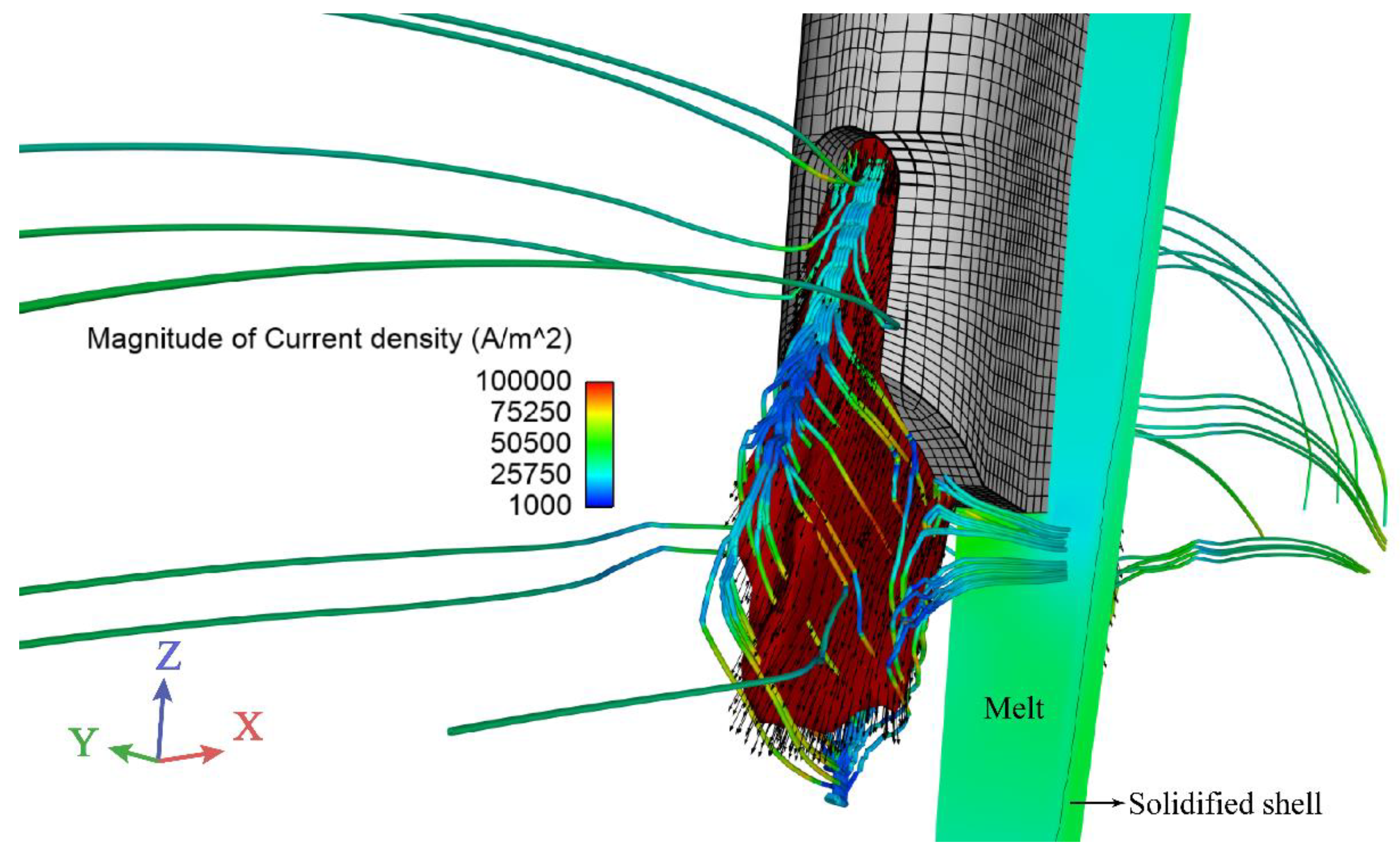
The exterior magnetic field remained constant. Therefore, the braking force was determined by the induced current density, as expressed by Equation (15). Induced current density lines from a nozzle jet are shown in Figure 5, in which the jet is a velocity isosurface of 0.65 m/s. The main closure of the current loops passed through the isosurface. However, under insulated wall conditions, loops would occur in a large volume in the mold if nonconducting walls were assumed, which was discussed by Miao [29]. Two conditions of fully insulated walls and perfectly conductive walls were also discussed in [31]. An extreme braking effect was observed with perfectly conductive walls, and strong instabilities were developed under fully insulated walls. Both conditions would exist in a real continuous casting process. In this work, a solidified shell with low electrical resistance was considered, although the wide and narrow faces were assumed to be insulated. As shown in half of the midsection of the narrow face in Figure 5, the current density in the solidified shell was higher than that in the adjacent melt. This is a more reasonable current distribution of a real casting process in theory. In addition, the streamlines changed direction frequently, like waves on the nozzle jets. This was a result of the unbalanced flow from the nozzle ports.
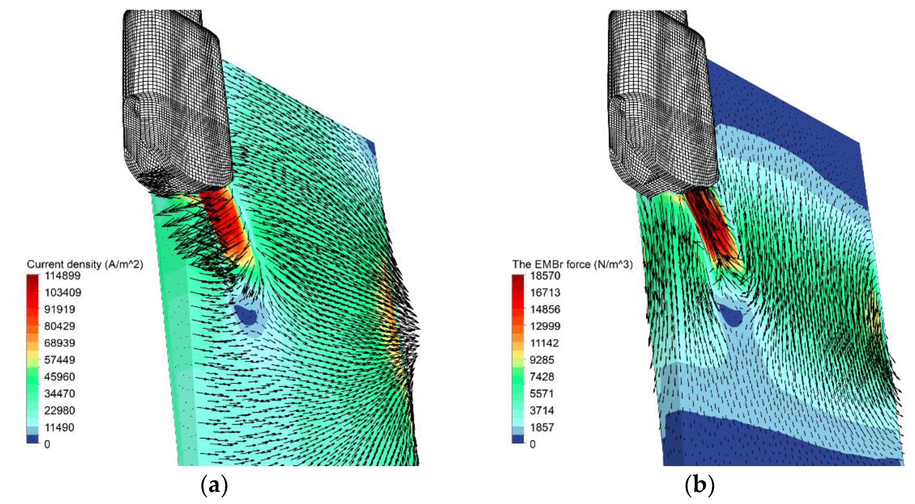
The current density and braking force induced by the EMBr are shown in Figure 6. In Figure 6a, the magnitude and direction of the induced current density are shown. The maximum current density and EMBr force appeared at the nozzle jet. In Figure 6b, the magnitude and direction of the EMBr force are shown. A dead zone was formed downstream of the jet, in which the current density and braking force were lower than those around the zone. The direction of the braking force was opposite to the jet direction in theory, and the main part was distributed in the mold. The braking force in most regions of the mold was downward due to an upward flow. It could be speculated that the flow field contributed to the removal of inclusions. A notable phenomenon was that the current density and EMBr force increased before the solidified shell of the narrow face.
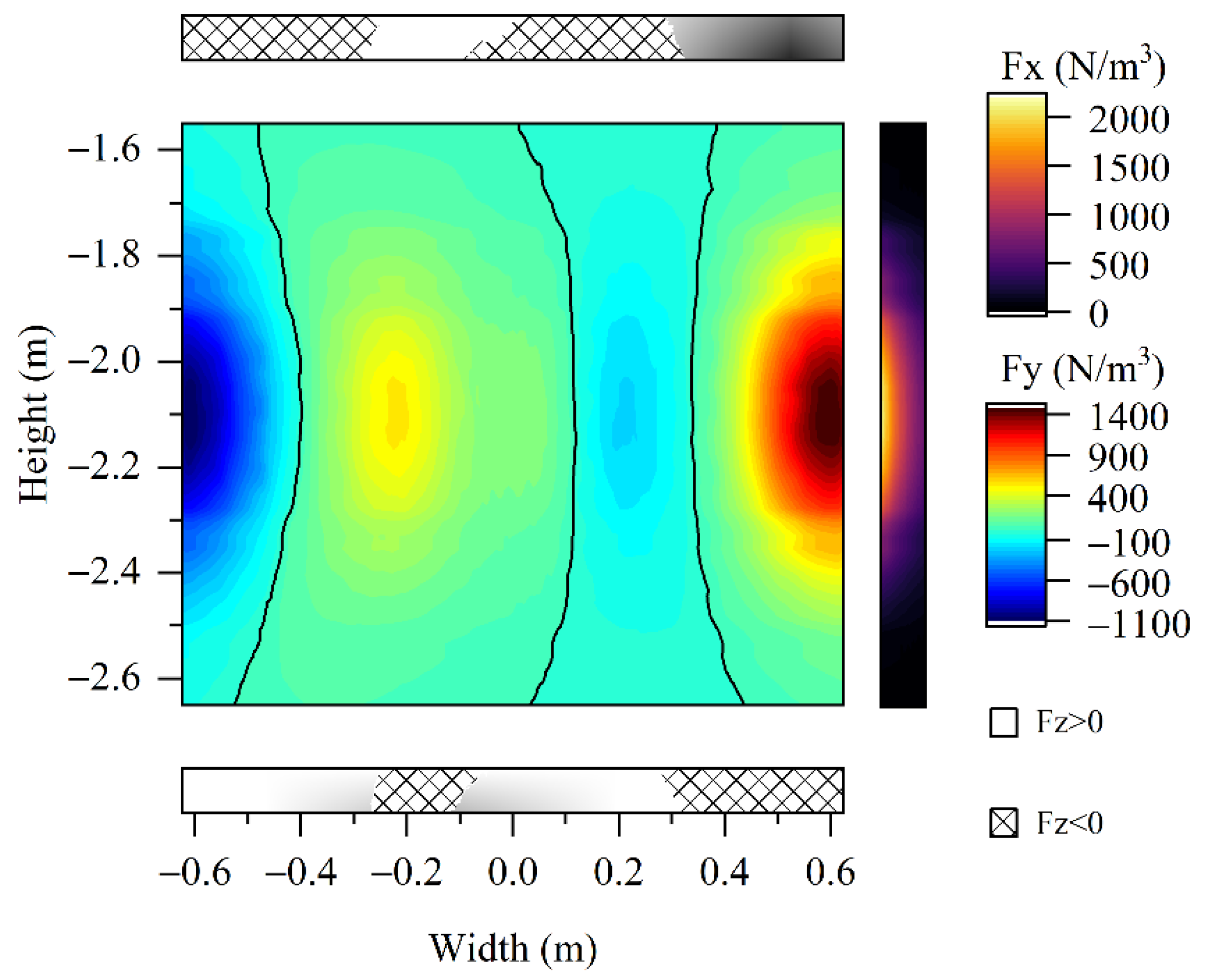
The time-averaged electromagnetic stirring force arising from SEMS is shown in Figure 7. Four planes were selected for a normal stirring force analysis. Cross-section 1 and cross-section 2 were the upper and lower edges of the SEMS magnet. The center height of the strand in Figure 7 was the same as that of the magnet. It appeared that most of the force was distributed between the two cross-sections. The maximum force appeared at the narrow face, which can also be seen in Figure 8. The force fluctuated in the x-axis direction (width direction of the strand). The stirring force in the normal direction to the four planes is given in Figure 8. In the Fy-plane, the stirring force in the thickness direction was divided into four zones by the three black lines; two were negative and two were positive. In the Fx-plane, the stirring force in the width direction was positive toward the positive direction of the x-axis (Figure 7). The main part was distributed in the iron core area. The directions of the normal stirring force in the two cross-sections were opposite. The magnitudes of the normal force in the two cross-sections are not shown here, as they were much smaller than those of the other two directions.

4.2. Melt Flow Field

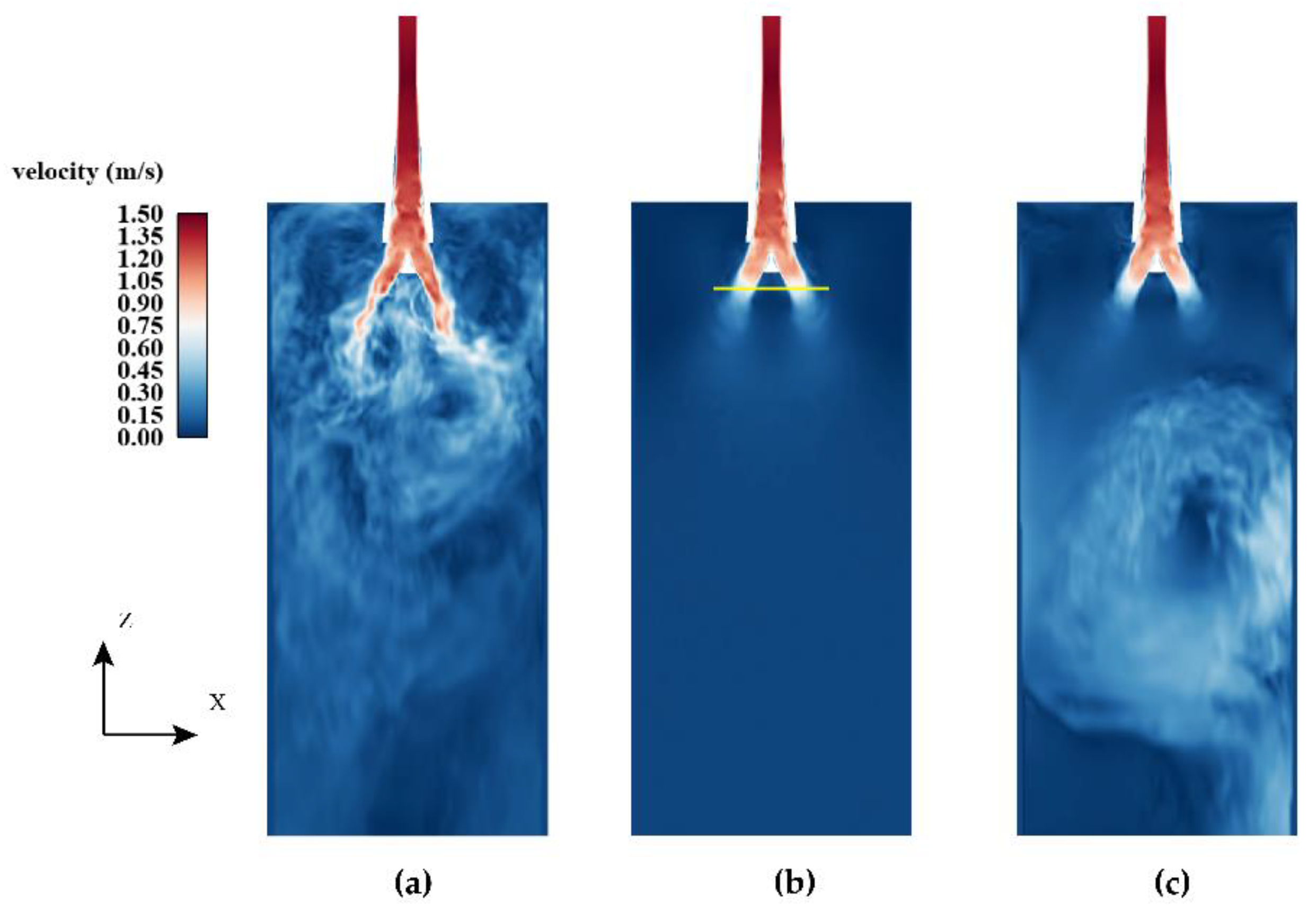
Contours of velocity magnitude for different cases are compared in Figure 9. As shown in Figure 9a, a highly turbulent flow was visible when EMBr was not applied, especially in the mold. The flow pattern was obviously asymmetrical. When EMBr was applied (Figure 9b), a stable jet discharged from nozzle ports developed. The flow field was balanced. When SEMS was applied (Figure 9c), the melt in the secondary cooling zone was stirred in the positive direction of the x-axis. Two streams were formed when the melt rushed to the narrow face. The upstream melt crashed to the nozzle jet, causing a large vortex on the vertical section of the wide face. Multiphysical fields at the centerline height of the SEMS are shown in Figure 10.
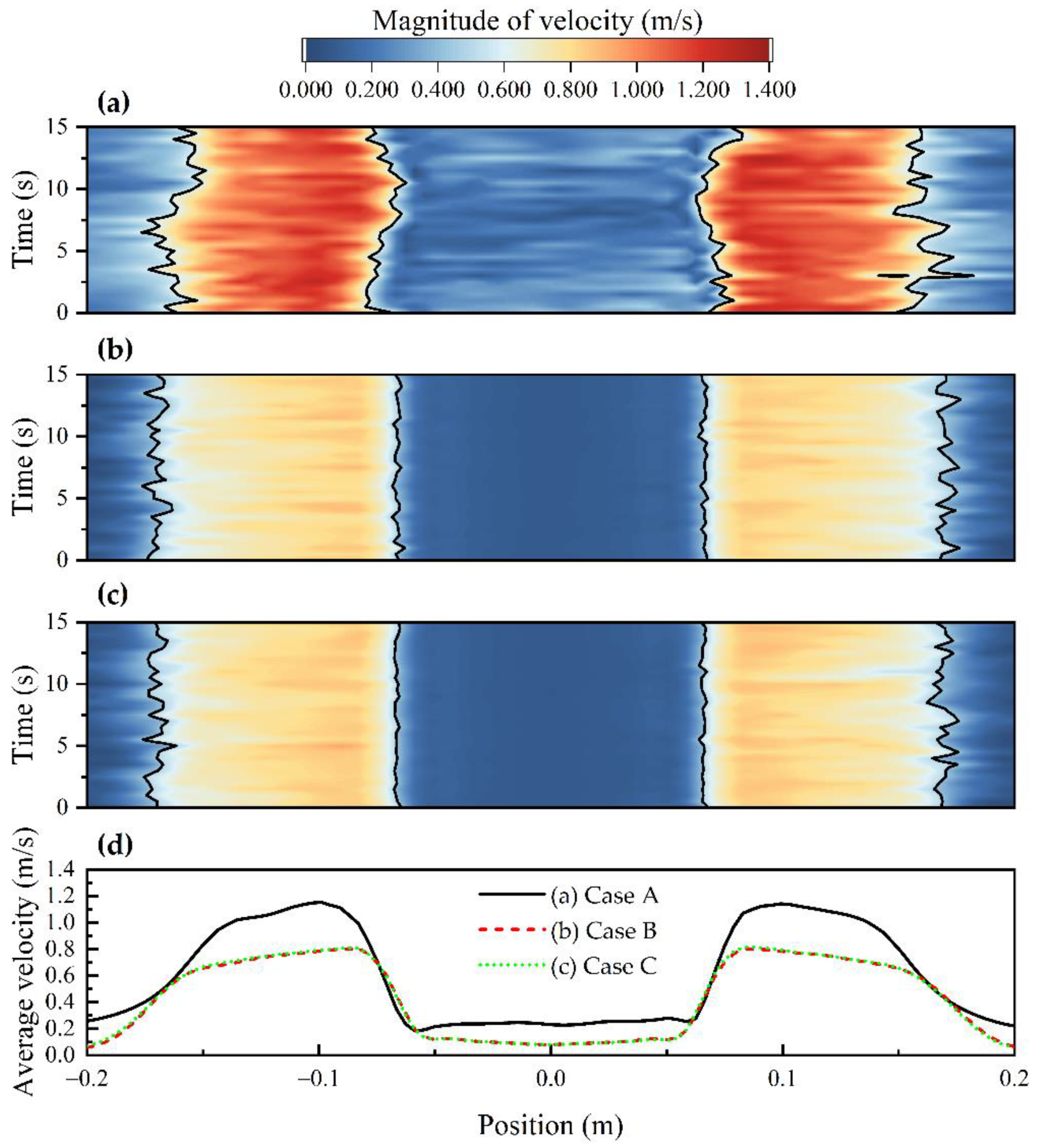
The effect of the EMBr on the nozzle jet was analyzed in three ways. First, the suppressive effect on the intensity of the nozzle jet was investigated. As seen in Figure 11a–c, the spatiotemporal velocity on the yellow line (Figure 9b) was plotted. A unified magnitude range of 0–1.4 m/s was used for an intuitionistic comparison. The maximum velocities monitored in Cases A (Figure 9a), B (Figure 9b), and C (Figure 9c) were 1.153, 0.805, and 0.817 m/s, respectively. It could be concluded from the color distribution and the maximum velocity magnitude that the intensity of the nozzle jet was obviously suppressed after applying the EMBr.
Second, the balance effect on the nozzle jet was explored. The distribution of the time-averaged velocity on the line is given in Figure 11d. The average values of each curve were 0.603, 0.434, and 0.436 m/s. A spatiotemporal average velocity was proposed here to represent the average value in time and space. The spatiotemporal average velocity could directly reflect the suppressive effect of the EMBr. Furthermore, the corresponding spatiotemporal average velocity of each case is displayed by a black curve in the first three diagrams of Figure 11. Apparently, the black curves noticeably fluctuated in Figure 11a, especially the two inner curves. When the EMBr was applied, a stable nozzle jet could be observed. It could be inferred that EMBr was beneficial for a relatively stable mold flow field and slag–metal interface, as the main turbulence energy was from the nozzle jet.
Third, the dispersion effect on the nozzle jet was examined. The high-speed zone on the yellow line, where the velocity magnitude was higher than the spatiotemporal average velocity, is shown in Figure 11a–c. The time-averaged lengths of the zone in each case were 0.180, 0.208, and 0.207 m. The zone became wider after applying the EMBr, and the magnitude of the spatiotemporal average velocity decreased. It could be concluded that the braking field could disperse nozzle jet energy. A uniform nozzle jet was formed after EMBr application. In addition, the SEMS had a mild effect on the nozzle jet, which can be seen in Figure 9c and from the above data. This effect might be negligible on the flow field in the mold, but it cannot be ignored when analyzing the distribution of the temperature and shell in a continuous casting process, especially in the secondary cooling zone.
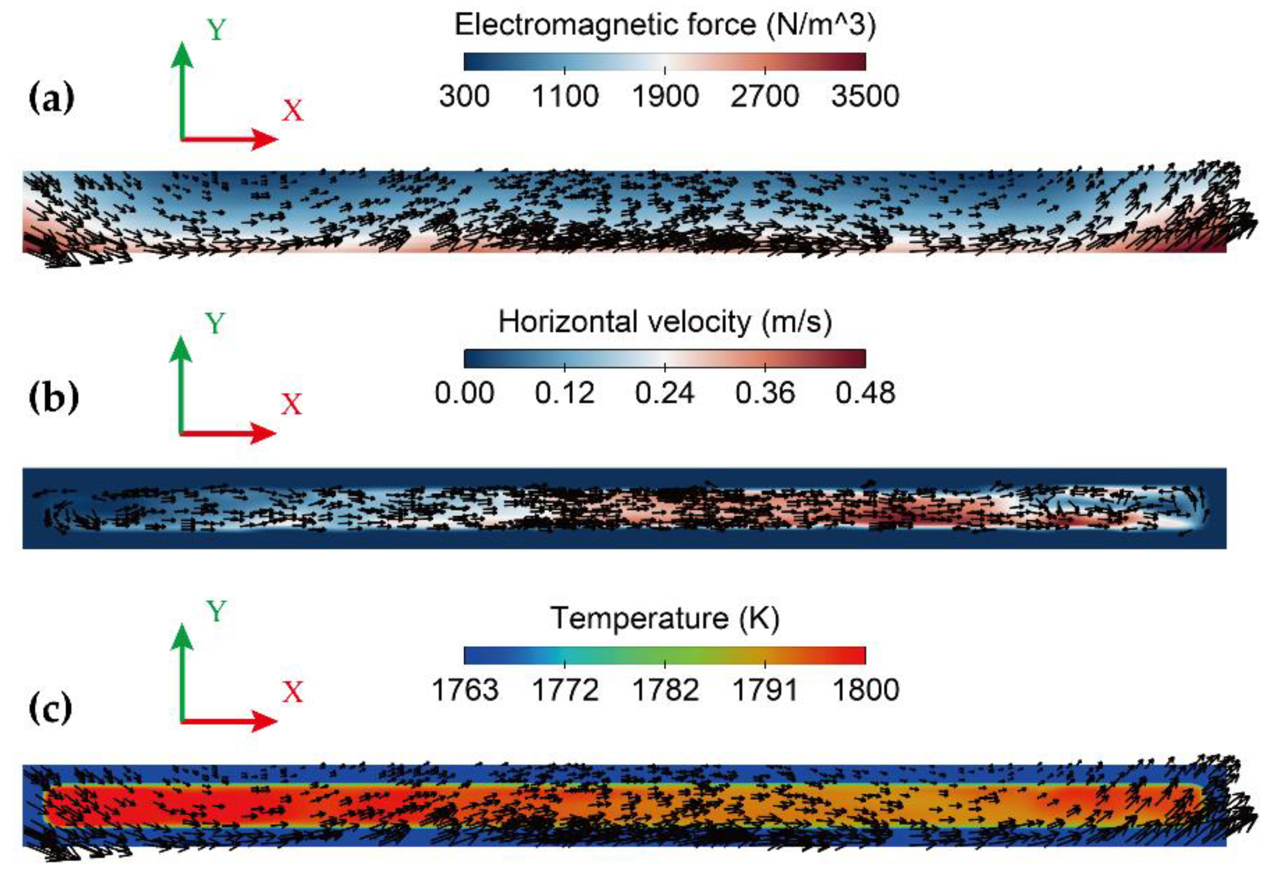
The predicted results in the strand at the mid-height of the SEMS are given in Figure 10. The distribution range of the electromagnetic force in Figure 10a was adjusted from 300 to 3500 N/m3 for a better display; the original range was 384 to 3883 N/m3. The stirring force near the SEMS side was greater than that of the loose side. The liquid melt was stirred in one direction, as shown in Figure 10b. The maximum horizontal velocity of the melt was 0.485 m/s. The high horizontal velocity zone was mainly distributed in the positive direction of the x-axis because of the longer stirring time. When the melt was stirred to the narrow face, a small vortex formed. This was a cause of the nonuniform distribution of the stirring force in the y-axis direction.
The distribution of the temperature field is shown in Figure 10c. The temperature field in the solidified shell is colored blue. The electromagnetic stirring force is mainly distributed in the solidified shell. In essence, the function of SEMS is to adjust the distribution of undercooling and then to provide a condition for nucleation. Thus, steel with a high equiaxed crystal ratio can be produced. In this work, the results showed that the melt temperature in the positive direction of the x-axis was slightly lower. A reasonable explanation is that the melt was stirred in the horizontal section, increasing the length of the cooling time. The undercooling became greater in a sense, which could improve the likelihood of nucleation. Furthermore, it could be inferred that there must be a reasonable range for the position of the SEMS. This position should not be too high, because the nucleation condition might not be met even if the melt was fully stirred. If the position is too far from the mold, the stirring effect might not be achieved due to the shielding effect of the solidified shell.
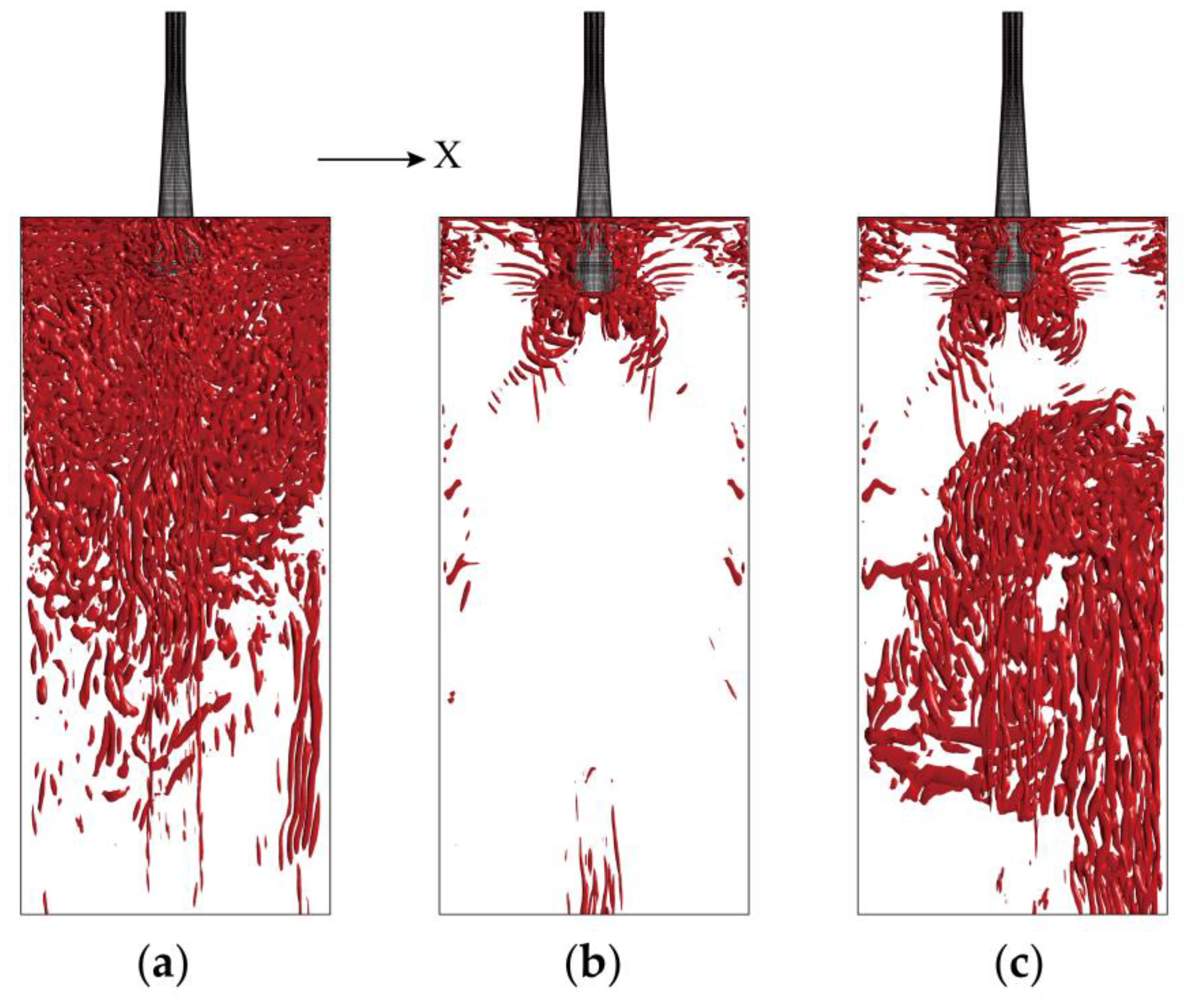
The distribution of the three-dimensional eddy structure based on the Q-criterion is shown in Figure 12. The value of the Q-criterion was 1 s−2. It appeared that the large-scale eddy structure could be obviously suppressed after the application of the EMBr, especially in the mold. In Figure 12b, highly turbulent flow was observed near the SEN. It was thought that the position of the EMBr magnet was slightly below the nozzle ports. This position tended to deflect the nozzle jet upwards [30] to accelerate surface flow near the SEN. In the case of the application of SEMS (Figure 12c), a large vortex was found in the strand, and the eddy structure occupied almost the entire liquid pool. It seemed that the turbulent flow in the secondary cooling zone was beneficial to even solidification when SEMS was applied. The undercooling could be redistributed, and other slab qualities might be improved.

4.3. Heat Transfer and Solidification

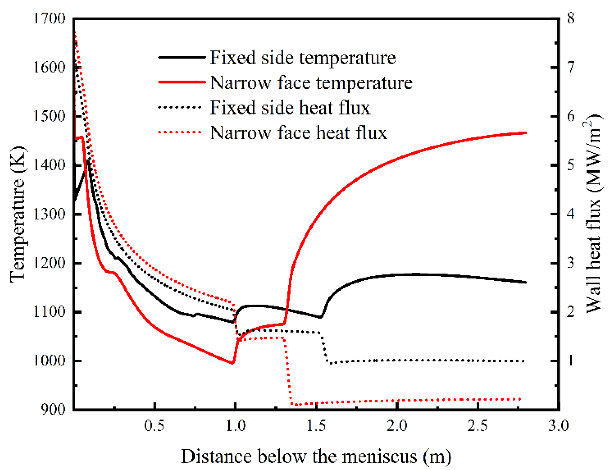
The temperature and heat flux curves on the centerlines of wide and narrow faces are shown in Figure 13. All narrow faces discussed in this section are in the positive direction of the x-axis in this work. The maximum heat fluxes were near the meniscus and were 7.23 and 7.76 MW/m2, respectively. The curves were nearly straight out of the mold, as air-mist nozzles and guiding rolls were not distinguished in the current work. The surface temperature decreased gradually in the mold; then, a sudden rise could be seen out of the mold outlet. The temperature trend of the fixed side was similar to the measured or predicted results in the slab continuous casting process [44,46]. A distinct result was observed on the narrow face. The temperature there increased faster than that on the fixed side because only natural convection and radiation heat transfer occurred.
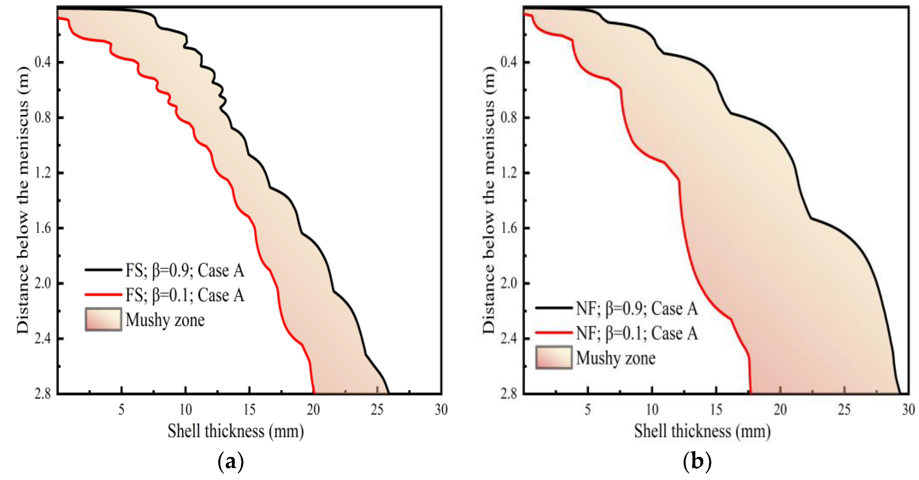
The growth of the solidified shell was mainly influenced by the heat removed from the strand surface. When the EMBr and SEMS were not applied, the mushy zone and solidified shell on the central section of the wide (Figure 14a) and narrow (Figure 14b) faces are given. The curve of the liquid fraction equal to 0.1 was regarded as a completely solidified shell, and the curve of the liquid fraction equal to 0.9 was regarded as the solidification front. The mushy zone on the narrow face was thicker, especially beyond the mold outlet. This indicated that the temperature gradient of the narrow face was lower, which can also be inferred from the heat flux in Figure 13.
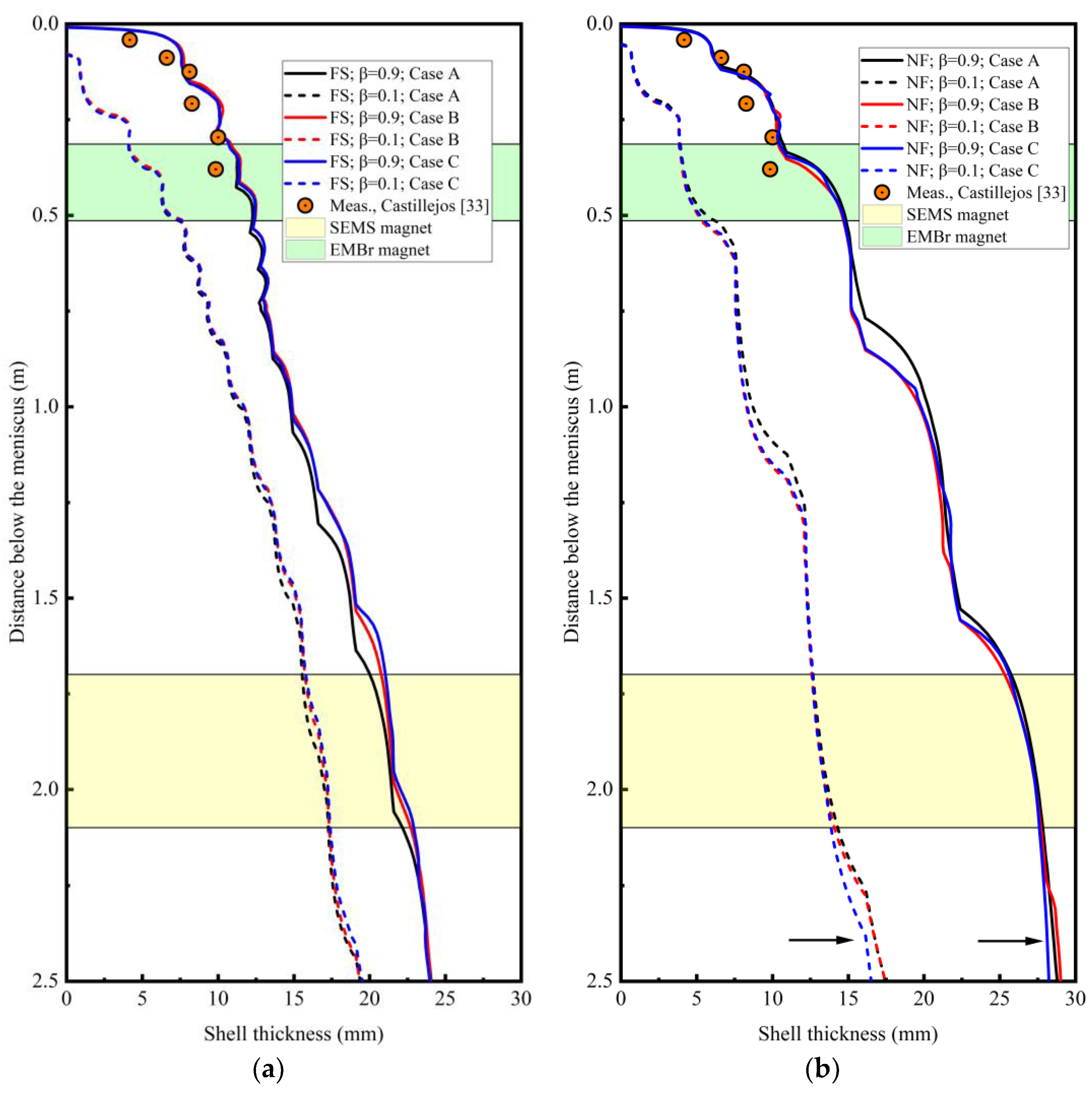
The solidified shell and solidification front fluctuated. The solidified shell thicknesses of the three cases and a model validation are given in Figure 15. The solidified shell thickness compares with Castillejos’s measurements in [33]. The measurements were carried out on a thin steel slab resulting from a break-out. No electromagnetic fields were applied, and the casting speed was 4.3 m/min. The predicted data for both the wide (Figure 15a) and narrow (Figure 15b) faces were compared with the measurements, because detailed measurement locations in the cross-section of the slab resulting from a break-out were not mentioned in the reference. Although the experimental measurements were not performed directly with the same settings in the current work, these measurements were valuable and reliable for an indirect validation of thin slab continuous casting processes [26]. As can be seen in Figure 15, good agreement was achieved with the solidification front (β = 0.9), as parts of the melt in the mushy zone may have solidified after the break-out. The experimental points also fluctuated, and a remelting phenomenon can be inferred from its trend. In the initial stage of solidification, the experimental thickness increased quickly, i.e., the solidification rate is faster. All these results can be predicted by the current model. Consequently, the present model is reliable, and the results above are important for revealing the sophisticated phenomena in CSP casters.
Compared with the condition of no electromagnetic control (Case A), the EMBr increased the shell thickness on the wide face and decreased the shell thickness on the narrow face, as shown in Figure 15. It seems that the solidified shell thicknesses on the wide and narrow faces tended to be close. The effect of SEMS on the shell thickness was not more obvious than that of the EMBr before the SEMS zone. Figure 15b shows that the solidified shell thickness on the narrow face became thinner beyond the SEMS zone. This was caused by the source term arising from SEMS and melt flow rushing to the narrow face.
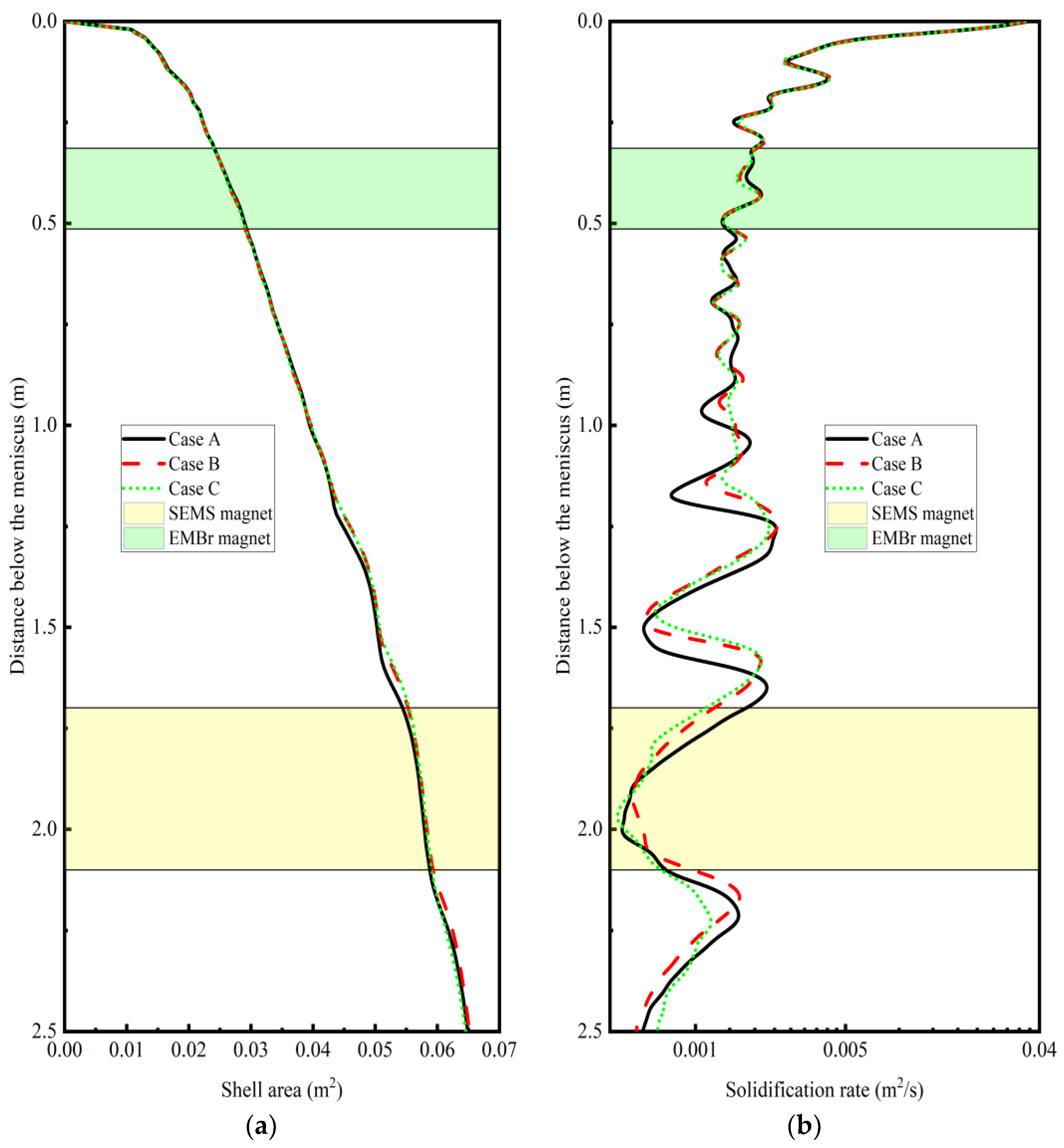
The total area of the solidified shell below the meniscus is profiled in Figure 16a. The distribution curves were quite flat compared with that of the shell thickness in Figure 15. A more uniform trend could be seen after the application of an electromagnetic field, although the difference was imperceptible before the mold outlet (1.0 m below the meniscus). The solidification rate of the solidified area is given in Figure 16b. In the initial stage of solidification, the solidification rate was quite fast, almost 40 times that of the secondary cooling zone. It could be inferred that the microstructure of the outer surface might be well-developed columnar crystals. The curve of the solidification rate with electromagnetic control was flatter than that without electromagnetic control. When SEMS was applied (Case C), the solidification rate became flatter, especially beyond the SEMS zone. It was conceivable that the stirred melt in the secondary zone slowed the speed of the solidification front. A more balanced and uniform shell was formed. This trend might also be beneficial to a uniform microstructure [25,47,48]. It could be referred that appropriate turbulence in the secondary zone was beneficial to the internal quality of steel, as shown in Figure 12.
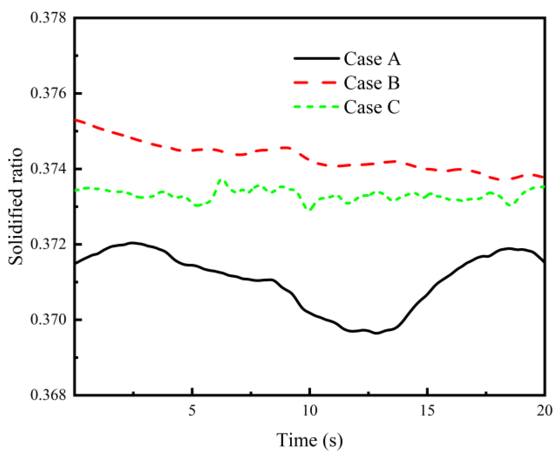
The solidified ratio of the mold outlet is shown in Figure 17. A visible characteristic is that the solidified shell was more stable under EMBr application. One reason was that the braking force of the EMBr on the nozzle jet could weaken the speed and intensity of the jet to the shell. This can also be seen in Figure 16b, in which the solidification rate curve becomes flatter near the mold outlet (1.0 m below the meniscus). The flow field in the mold was more stable, and more energy input was distributed to the secondary cooling zone. Thus, the solidified shell thickness at the mold outlet increased when the EMBr was applied. As a whole, the energy distribution tended to be uniform. The effect of the SEMS could be inferred from flow field characteristics. When the liquid melt rushed to the narrow face, one stream flowed back to the mold. A part of the energy was transported into the mold. Therefore, the solidified ratio of the mold outlet was lower than that without the EMBr. It is logical that the average solidified ratio in Case A was the minimum, with an average value of 0.371, and the average ratios in Cases B and C were 0.374 and 0.373, respectively.

5. Conclusions

As mentioned before, few studies have focused on melt flow and solidification in a thin slab caster with simultaneous application of an EMBr and SEMS. The purpose of this study was to describe and reveal the sophisticated phenomena in a real thin slab caster with and without electromagnetic controls. The following conclusions could be drawn:
(1) It was observed that the current density streamlines induced by the EMBr were pulsatile near the nozzle jet. The current tended to follow a path through the solidified shell as the conductivity increased after solidification. Three effects of the EMBr on melt flow could be concluded, and a novel finding was that the EMBr had a dispersion effect on the nozzle jet, which was beneficial to a flatter nozzle jet. This might also be a reason contributing to stable and balanced flow in the mold.
(2) A large vortex was observed in the vertical direction of the strand as the stirring force was in a fixed direction. A highly turbulent flow was caused in the liquid pool of the strand. The main stirring force was shielded by the solidified shell. There might be a reasonable range for the SEMS position when considering both the undercooling and stirring efficiency.
(3) The heat discharged from nozzle ports was redistributed under the influence of an electromagnetic field. An overall trend was that the solidified shell became more uniform under electromagnetic control. The solidification rate of the solidified shell area became stable near the mold outlet, which was obviously influenced by the speed and intensity of the nozzle jet when no EMBr was applied. The solidification rate decreased and became more stable after the SEMS application, even though the stirring was in a fixed direction. This was beneficial to the internal quality of the steel.
These preliminary results demonstrated that multiphysical fields in thin slab casters under electromagnetic control are worth exploring. Numerical analysis is a low-cost way to provide insight into the striking phenomena in a strand. Future work is planned to predict the microstructure in the shell and explore reasonable conditions for electromagnetic control. This would be beneficial to the production of high-grade steel in a CSP process.

Author Contributions

C.W. developed the model, analyzed data and wrote the paper; Z.L. and B.L. partly contributed to the data analysis. All authors have read and agreed to the published version of the manuscript.

Funding

This work was financially supported by the National Natural Science Foundation of China (No. 51974071) and Fundamental Research Funds for the Central Universities (No. N182505039 and No. N2025020).

Conflicts of Interest

The authors declare no conflict of interest.

References

  1. Michel, J.P.; Jonas, J.J. Precipitation kinetics and solute strengthening in high temperature austenites containing al and n. Acta Met. 1981, 29, 513–526. [Google Scholar] [CrossRef]
  2. Kang, Y.L.; Yu, H.; Fu, J.; Wang, K.; Wang, Z.B. Morphology and precipitation kinetics of aln in hot strip of low carbon steel produced by compact strip production. Mater. Sci. Eng. A Struct. Mater. Prop. 2003, 351, 265–271. [Google Scholar] [CrossRef]
  3. Park, J.K.; Thomas, B.G.; Samarasekera, I.V.; Yoon, U.S. Thermal and mechanical behavior of copper molds during thin-slab casting (i): Plant trial and mathematical modeling. Met. Mater. Trans. B 2002, 33, 425–436. [Google Scholar] [CrossRef]
  4. Morales, R.D.; Tang, Y.; Nitzl, G.; Eglsaeer, C.; Hackl, G. Design of a submerged entry nozzle for thin slab molds operating at high casting speeds. ISIJ Int. 2012, 52, 1607–1615. [Google Scholar] [CrossRef] [Green Version]
  5. Qiao, J.L.; Guo, F.H.; Hu, J.W.; Xiang, L.; Qiu, S.T.; Wang, H.J. Precipitates in compact strip production (csp) process non-oriented electrical steel. Metals 2020, 10, 1301. [Google Scholar] [CrossRef]
  6. Cho, S.M.; Thomas, B.G. Electromagnetic forces in continuous casting of steel slabs. Metals 2019, 9, 471. [Google Scholar] [CrossRef] [Green Version]
  7. Cukierski, K.; Thomas, B.G. Flow control with local electromagnetic braking in continuous casting of steel slabs. Met. Mater. Trans. B 2008, 39, 94–107. [Google Scholar] [CrossRef]
  8. Wang, Y.F.; Zhang, L.F. Fluid flow-related transport phenomena in steel slab continuous casting strands under electromagnetic brake. Met. Mater. Trans. B 2011, 42, 1319–1351. [Google Scholar] [CrossRef]
  9. Li, F.; Wang, E.G.; Feng, M.J.; Li, Z. Simulation research of flow field in continuous casting mold with vertical electromagnetic brake. ISIJ Int. 2015, 55, 814–820. [Google Scholar] [CrossRef] [Green Version]
  10. Li, Z.; Wang, E.G.; Zhang, L.T.; Xu, Y.; Deng, A.Y. Influence of vertical electromagnetic brake on the steel/slag interface behavior in a slab mold. Met. Mater. Trans. B 2017, 48, 2389–2402. [Google Scholar] [CrossRef]
  11. Singh, R.; Thomas, B.G.; Vanka, S.P. Large eddy simulations of double-ruler electromagnetic field effect on transient flow during continuous casting. Met. Mater. Trans. B 2014, 45, 1098–1115. [Google Scholar] [CrossRef] [Green Version]
  12. Wang, Q.Q.; Zhang, L.F. Influence of fc-mold on the full solidification of continuous casting slab. JOM 2016, 68, 2170–2179. [Google Scholar] [CrossRef]
  13. Xu, L.; Wang, E.G.; Karcher, C.; Deng, A.Y.; Xu, X.J. Numerical simulation of the effects of horizontal and vertical embr on jet flow and mold level fluctuation in continuous casting. Met. Mater. Trans. B 2018, 49, 2779–2793. [Google Scholar] [CrossRef]
  14. Chaudhary, R.; Thomas, B.G.; Vanka, S.P. Effect of electromagnetic ruler braking (embr) on transient turbulent flow in continuous slab casting using large eddy simulations. Met. Mater. Trans. B 2012, 43, 532–553. [Google Scholar] [CrossRef]
  15. Schurmann, D.; Glavinic, I.; Willers, B.; Timmel, K.; Eckert, S. Impact of the electromagnetic brake position on the flow structure in a slab continuous casting mold: An experimental parameter study. Met. Mater. Trans. B 2020, 51, 61–78. [Google Scholar] [CrossRef]
  16. Chaudhary, R.; Ji, C.; Thomas, B.G.; Vanka, S.P. Transient turbulent flow in a liquid-metal model of continuous casting, including comparison of six different methods. Met. Mater. Trans. B 2011, 42, 987–1007. [Google Scholar] [CrossRef]
  17. Li, B.K.; Tsukihashi, F. Effects of electromagnetic brake on vortex flows in thin slab continuous casting mold. ISIJ Int. 2006, 46, 1833–1838. [Google Scholar] [CrossRef] [Green Version]
  18. Harada, H.; Toh, T.; Ishii, T.; Kaneko, K.; Takeuchi, E. Effect of magnetic field conditions on the electromagnetic braking efficiency. ISIJ Int. 2001, 41, 1236–1244. [Google Scholar] [CrossRef]
  19. Tian, X.Y.; Li, B.W.; He, J.C. Electromagnetic brake effects on the funnel shape mold of a thin slab caster based on a new type magnet. Met. Mater. Trans. B 2009, 40, 596–604. [Google Scholar] [CrossRef]
  20. Dubke, M.; Tacke, K.-H.; Spitzer, K.-H.; Schwerdtfeger, K. Flow fields in electromagnetic stirring of rectangular strands with linear inductors: Part i. Theory and experiments with cold models. Met. Trans. B 1988, 19, 581–593. [Google Scholar] [CrossRef]
  21. Dubke, M.; Tacke, K.-H.; Spitzer, K.-H.; Schwerdtfeger, K. Flow fields in electromagnetic stirring of rectangular strands with linear inductors: Part ii. Computation of flow fields in billets, blooms, and slabs of steel. Met. Trans. B 1988, 19, 595–602. [Google Scholar] [CrossRef]
  22. Kunstreich, S. Electromagnetic stirring for continuous casting (part 2). Rev. Met. Cah. Inf. Technol. 2003, 100, 1043–1061. [Google Scholar] [CrossRef]
  23. Gong, J.; Liu, H.P.; Wang, X.H.; Bao, Y.P. Numerical simulation of electromagnetic field and flow pattern in a continuous slab caster with in-roll type strand electromagnetic stirring. J. Iron Steel Res. Int. 2015, 22, 414–422. [Google Scholar] [CrossRef]
  24. Niu, L.; Qiu, S.T.; Zhao, J.X.; Chen, Y.Q.; Yang, S.F. Processing parameter optimization for continuous casting of 38crmoal round bloom based on a prediction model of the equiaxed crystal ratio. Ironmak. Steelmak. 2019, 46, 835–844. [Google Scholar] [CrossRef]
  25. Shibata, H.; Itoyama, S.; Kishimoto, Y.; Takeuchi, S.; Siekiguchi, H. Prediction of equiaxed crystal ratio in continuously cast steel slab by simplified columnar-to-equiaxed transition model. ISIJ Int. 2006, 46, 921–930. [Google Scholar] [CrossRef]
  26. Vakhrushev, A.; Wu, M.; Ludwig, A.; Tang, Y.; Hackl, G.; Nitzl, G. Numerical investigation of shell formation in thin slab casting of funnel-type mold. Met. Mater. Trans. B 2014, 45, 1024–1037. [Google Scholar] [CrossRef]
  27. Vakhrushev, A.; Kharicha, A.; Wu, M.; Ludwig, A.; Nitzl, G.; Tang, Y.; Hackl, G.; Watziger, J.; Rodrigues, C.M.G. On modelling viscoplastic behavior of the solidifying shell in the funnel-type continuous casting mold. IOP Conf. Ser. Mater. Sci. Eng. 2019, 529, 012081. [Google Scholar] [CrossRef]
  28. Vakhrushev, A.; Kharicha, A.; Wu, M.; Ludwig, A.; Nitzl, G.; Tang, Y.; Hackl, G.; Watzinger, J.; Rodrigues, C.M.G. Modelling viscoplastic behavior of solidifying shell under applied electromagnetic breaking during continuous casting. IOP Conf. Ser. Mater. Sci. Eng. 2020, 861, 012015. [Google Scholar] [CrossRef]
  29. Miao, X.C.; Timmel, K.; Lucas, D.; Ren, Z.M.; Eckert, S.; Gerbeth, G. Effect of an electromagnetic brake on the turbulent melt flow in a continuous-casting mold. Met. Mater. Trans. B 2012, 43, 954–972. [Google Scholar] [CrossRef]
  30. Singh, R.; Thomas, B.G.; Vanka, S.P. Effects of a magnetic field on turbulent flow in the mold region of a steel caster. Met. Mater. Trans. B 2013, 44, 1201–1221. [Google Scholar] [CrossRef]
  31. Vakhrushev, A.; Kharicha, A.; Liu, Z.Q.; Wu, M.H.; Ludwig, A.; Nitzl, G.; Tang, Y.; Hackl, G.; Watzinger, J. Electric current distribution during electromagnetic braking in continuous casting. Met. Mater. Trans. B 2020, 51, 2811–2828. [Google Scholar] [CrossRef]
  32. Liu, Z.Q.; Vakhrushev, A.; Wu, M.H.; Karimi-Sibaki, E.; Kharicha, A.; Ludwig, A.; Li, B.K. Effect of an electrically-conducting wall on transient magnetohydrodynamic flow in a continuous-casting mold with an electromagnetic brake. Metals 2018, 8, 609. [Google Scholar] [CrossRef] [Green Version]
  33. Camporredondo, S.J.E.; Castillejos, E.A.H.; Acosta, G.F.A.; Gutiérrez, M.E.P.; Herrera, G.M.A. Analysis of thin-slab casting by the compact-strip process: Part i. Heat extraction and solidification. Met. Mater. Trans. B 2004, 35, 541–560. [Google Scholar] [CrossRef]
  34. Tian, X.Y.; Zou, F.; Li, B.W.; He, J.C. Numerical analysis of coupled fluid flow, heat transfer and macroscopic solidification in the thin slab funnel shape mold with a new type embr. Metall. Mater. Trans. B 2010, 41, 112–120. [Google Scholar] [CrossRef]
  35. Nicoud, F.; Ducros, F. Subgrid-scale stress modelling based on the square of the velocity gradient tensor. Flow. Turbul. Combust. 1999, 62, 183–200. [Google Scholar] [CrossRef]
  36. ANSYS FLUENT 14. 5-Theory Guide; ANSYS. Inc.: Canonsburg, PA, USA, 2012. [Google Scholar]
  37. Singh, V.; Das, S.K. Thermo-fluid mathematical modeling of steel slab caster: Progress in 21st century. ISIJ Int. 2016, 56, 1509–1518. [Google Scholar] [CrossRef] [Green Version]
  38. Schneider, M.C.; Gu, J.P.; Beckermann, C.; Boettinger, W.J.; Kattner, U.R. Modeling of micro- and macrosegregation and freckle formation in single-crystal nickel-base superalloy directional solidification. Met. Mater. Trans. A 1997, 28, 1517–1531. [Google Scholar] [CrossRef]
  39. Wang, Y.D.; Chen, W.; Jiang, D.B.; Zhang, L.F. Effect of the gap between copper mold and solidified shell on the fluid flow in the continuous casting strand with mold electromagnetic stirring. Steel Res. Int. 2020, 91, 1900470. [Google Scholar] [CrossRef]
  40. Li, X.L.; Li, B.K.; Liu, Z.Q.; Niu, R.; Huang, X.C. Large eddy simulation of electromagnetic three-phase flow in a round bloom considering solidified shell. Steel Res. Int. 2019, 90, 1800133. [Google Scholar] [CrossRef]
  41. Liu, H.P.; Yang, C.Z.; Zhang, H.; Zhai, Q.J.; Gan, Y. Numerical simulation of fluid flow and thermal characteristics of thin slab in the funnel-type molds of two casters. ISIJ Int. 2011, 51, 392–401. [Google Scholar] [CrossRef] [Green Version]
  42. Camporredondo, S.J.E.; Acosta, G.F.A.; Castillejos, E.A.H.; Gutiérrez, M.E.P.; González de la, P.R. Analysis of thin-slab casting by the compact-strip process: Part ii. Effect of operating and design parameters on solidification and bulging. Met. Mater. Trans. B 2004, 35, 561–573. [Google Scholar] [CrossRef]
  43. Petrus, B.; Zheng, K.; Zhou, X.; Thomas, B.G.; Bentsman, J. Real-time, model-based spray-cooling control system for steel continuous casting. Met. Mater. Trans. B 2010, 42, 87–103. [Google Scholar] [CrossRef]
  44. Yang, J.; Xie, Z.; Ning, J.; Liu, W.H.; Ji, Z.P. A framework for soft sensing of liquid pool length of continuous casting round blooms. Met. Mater. Trans. B 2014, 45, 1545–1556. [Google Scholar] [CrossRef]
  45. Timmel, K.; Eckert, S.; Gerbeth, G. Experimental investigation of the flow in a continuous-casting mold under the influence of a transverse, direct current magnetic field. Met. Mater. Trans. B 2011, 42, 68–80. [Google Scholar] [CrossRef]
  46. Liu, Z.Q.; Li, L.M.; Li, B.K.; Jiang, M.F. Large eddy simulation of transient flow, solidification, and particle transport processes in continuous-casting mold. JOM 2014, 66, 1184–1196. [Google Scholar] [CrossRef]
  47. Gäumann, M.; Bezençon, C.; Canalis, P.; Kurz, W. Single-crystal laser deposition of superalloys: Processing–microstructure maps. Acta Mater. 2001, 49, 1051–1062. [Google Scholar] [CrossRef]
  48. Liu, Z.Q.; Niu, R.; Wu, Y.D.; Li, B.K.; Gan, Y.; Wu, M. Physical and numerical simulation of mixed columnar-equiaxed solidification during cold strip feeding in continuous casting. Int. J. Heat Mass Transf. 2021, 173, 121237. [Google Scholar] [CrossRef]
Figure 1. Overall schematic diagram of the compact strip production (CSP). The top edge of the electromagnetic brake (EMBr) magnet was immediately below the bottom end of the submerged entry nozzle (SEN). The strand electromagnetic stirring (SEMS) system was placed at the fixed side.
Metals 11 00948 g001
Figure 2. Schematic diagram of SEMS system in the top view. SEMS system was located at the fixed side.
Metals 11 00948 g002
Figure 3. (a) Physical model and boundary conditions. (b) Geometry of the SEN.
Metals 11 00948 g003
Figure 4. (a) Contour plot of the exterior magnetic field arising from the EMBr in one quarter of the mold. The x-, y-, and z-axis were along the direction of the width, thickness, and height of the mold, respectively. The origin had the same height as the pole center of the EMBr magnet. (b) Field strength in the three lines. The negative direction of the z-axis was the same as the casting direction.
Metals 11 00948 g004
Figure 5. Induced current density streamlines in the vicinity of a jet discharging from nozzle ports. The jet was a velocity isosurface of 0.65 m/s with a carmine color. Half of the midsection of the narrow faces was contoured by the induced current density with the same legend. The interface of the solidified shell and melt is represented by a black solid line. Both the EMBr and SEMS were applied in this case.
Metals 11 00948 g005
Figure 6. (a) The magnitude and direction of the induced current density arising from EMBr. (b) The magnitude and direction of the EMBr force.
Metals 11 00948 g006
Figure 7. Time-averaged electromagnetic stirring force in the middle section of the wide face. A strand 1.1 m long in the casting direction was chosen.
Metals 11 00948 g007
Figure 8. Normal SEMS force in the four planes (Figure 7).
Metals 11 00948 g008
Figure 9. Contours of velocity magnitude in the wide face mid-plane: (a) Case A; (b) Case B; (c) Case C. A 0.4 meters long yellow line, located between the nozzle bottom and the EMBr centerline, was selected to monitor the instantaneous velocity distribution under three cases.
Metals 11 00948 g009
Figure 10. Simulation results in the strand at the mid-height of the SEMS: (a) the magnitude and direction of the time-averaged electromagnetic stirring force; (b) the magnitude and direction of the horizontal velocity; and (c) the temperature distribution. The vector arrow in (c) is the electromagnetic stirring force.
Metals 11 00948 g010
Figure 11. Spatiotemporal velocity plots (on the yellow line in Figure 9b) of the nozzle jet discharging from nozzle ports: (a) Case A; (b) Case B; (c) Case C; (d) an analysis of the time-averaged velocity. All four diagrams have the same horizontal coordinates. The black curve in the first three diagrams corresponds to the spatiotemporal average velocity.
Metals 11 00948 g011
Figure 12. Isosurfaces of the Q-criterion (1 s−2): (a) Case A; (b) Case B; (c) Case C.
Metals 11 00948 g012
Figure 13. Heat flux profiles and strand surface temperatures as a function of distance from the meniscus. The centerlines of the narrow and wide faces were monitored.
Metals 11 00948 g013
Figure 14. Solidified shell thickness at the centerline of wide and narrow faces in Case A: (a) fixed side (FS); (b) narrow face (NF).
Metals 11 00948 g014
Figure 15. Profiles of the liquid fraction along the casting direction under the three cases: (a) in the midsection of the fixed side (FS); (b) on the narrow face (NF). The narrow face was in the stirring direction.
Metals 11 00948 g015
Figure 16. The (a) solidified shell area and (b) solidification rate with the distance below the meniscus.
Metals 11 00948 g016
Figure 17. Solidified ratio at the mold outlet.
Metals 11 00948 g017
Table 1. Process parameters.
ParameterValue
Mold
Width1250 mm
Funnel Part Height850 mm
Vertical Part Height250 mm
Vertical Part Thickness85 mm
Maximum Thickness195 mm
Casting Speed4 m/min
SEN
Inlet Diameter80 mm
Port Height135 mm
Port Width33.8 mm
Inlet Velocity1.38 m/s
Submergence Depth180 mm
EMBr
Magnet Width1200 mm
Magnet Height200 mm
Windings Per Coil100
Current250 A
SEMS
Magnet Height400 mm
Windings Per Coil100
Max Current600 A
Frequency4 Hz
Cases
Case ANo EMBr, No SEMS
Case BEMBr, No SEMS
Case CEMBr, SEMS
Table 2. Key parameters for calculating the heat flux profile on wide and narrow faces.
ParameterValue
Wide Faces
Mold
(Cooling Water)
Flow Rate6200 L/min
Temperature Increase18 K
GridLength0.49 m
Water Flow Rate1964 L/min
Seg.2Length1.27 m
Water Flow Rate1668 L/min
Narrow Faces
Mold
(Cooling Water)
Flow Rate230 L/min
Temperature Increase15 K
Wide and Narrow Faces
RingLength0.06 m
Water Flow Rate300 L/min
Natural Convection8.7 W/(m2 K)
Ambient Temperature300 K
Table 3. Material parameters.
ParameterValue
Density, ρ6949 kg/m3
Specific Heat, cp700 J/(kg K)
Conductivity, λl35 W/(m K)
Laminar Viscosity, μl0.006 kg/(m s)
Latent Heat, L271,000 J/kg
Solidus Temperature, Tsolidus1763.2 K
Liquidus Temperature, Tliquidus1790.5 K
Electrical Conductivity of Liquid Steel, σliq714,000 S/m
Electrical Conductivity of Solid Steel, σsol999,600 S/m
Publisher’s Note: MDPI stays neutral with regard to jurisdictional claims in published maps and institutional affiliations.