Review

Laser Beam and Laser-Arc Hybrid Welding of Aluminium Alloys

SINTEF Industry, P.O. Box 4760 Torgarden, NO-7465 Trondheim, Norway
*
Author to whom correspondence should be addressed.
Metals 2021, 11(8), 1150; https://doi.org/10.3390/met11081150
Submission received: 18 May 2021 / Revised: 20 June 2021 / Accepted: 28 June 2021 / Published: 21 July 2021

Abstract

:
Aluminium alloys are widely used in many industries due to their high strength-to-weight ratios and resistance to corrosion. Due to their specific thermophysical properties and intricate physical metallurgy, these alloys are challenging to weld. Work-hardened alloys may experience strength loss in heat-affected zones (HAZ). The strength of precipitation-hardened alloys is severely damaged in both HAZ and weld metal due to coarsening or full dissolution. The high thermal conductivity and reflectivity of aluminium causes lower laser beam absorptivity with lower processing efficiency. Weld imperfections such as porosity, humping, and underfills are frequently formed due to the low melting point and density promoting high liquidity with low surface tension. Porosity is the most persistent imperfection and is detrimental for mechanical properties. In this work, extensive review was made on laser beam and laser-arc hybrid welding of aluminium alloys. Solidification cracking, evaporation of alloying elements, porosity and keyhole stability, and other challenges are studied in detail. The current development of laser welding of aluminium alloys is not so mature and new discoveries will be made in the future including the use of newly developed laser systems, welding consumables, welding methods, and approaches.

1. Introduction

Aluminium alloys are more widely used nowadays in vast variety of industries due to their low weight (density 2.7 g/cm3), high corrosion resistance, excellent formability, high toughness at cryogenic temperatures possessing face-centred cubic (FCC) crystal structure, high thermal and electrical conductivity, and they are relatively inexpensive. In addition, Al has excellent recyclability [1], and is thus widely used in the production of car bodies [2], different structural components, shipbuilding, and as packaging material. Recently, aluminium alloys became more attractive in electrical battery assemblies [3] due to high conductivity and low density. Aluminium alloys exhibit good mechanical properties among other materials and possess high strength-to-weight ratios [4]. Their weldability may have significant challenges, especially in joining precipitation-hardened aluminium alloys with high requirements for weld quality.
Gas metal arc welding (GMAW), which is also known as metal inert/active gas (MIG/MAG), has been the most used process in the joining of aluminium alloys for structural applications. Unfortunately, the process requires trivial bevel preparation, raising costs [5]. Moreover, Kim et al. [6] evaluated multi-pass deposition, which is time-consuming even with the twin wire method. The use of relatively high heat input may also result in severe distortions which largely restrict the productivity and weld quality.
Laser beam welding (LBW) has been used for many decades, providing a significant increase in productivity due to high penetration depths. To improve the process productivity and to enhance quality further, laser-arc hybrid welding (LAHW) is an alternative option. The application of laser in aluminium welding introduces new challenges. These are: (i) The surface of aluminium is highly reflective, and the laser beam must have an inclination angle of at least 8–10° to avoid high back reflections reaching unfavourable Brewster angles for high absorption; otherwise, the optics system may be damaged. This fact may, in turn, reduce the process efficiency. (ii) High thermal conductivity and low viscosity make it difficult to perform laser welding. Hu and Richardson [7] evaluated transverse solidification cracking and found that it was related to an elongated temperature distribution in the welding direction, which induced a transverse tensile strain in the weld fusion zone during the cooling phase. (iii) High tendency to porosity [8,9,10], loss of alloying elements, and solidification cracking, which are detrimental to the weld integrity. Porosity is a well-known issue in aluminium welding and occurs when humidity is not sufficiently removed prior to welding. (iv) Kawahito et al. [11] indicated that LBW has restrictions to gap tolerances and misalignment due to small spot area of the focused beam. Therefore, joint preparation can be time-consuming [12,13].
Work-hardened (non-heat treatable) aluminium alloys such as the 5xxx series will lose a considerable amount of their strength in the heat affected zone (HAZ) in the case of arc welding due to the annihilation of dislocations [14]. In fusion welding of Al alloys, a wide HAZ is formed due to high heat conduction. Since laser welding provides lower heat input and more concentrated energy, it may be questioned if less strength loss can be achieved due to narrower HAZ. Likewise, heat treatable alloys such as 6xxx and 7xxx may undergo a severe strength loss in the HAZ. In fact, up to a 50% strength reduction may be accounted for in the design of aluminium structures according to Eurocode 9 [15]. However, a natural or artificial heat treatment after welding may restore some of the strength, but such treatment will raise the fabrication costs significantly.
Friction-stir welding (FSW) is frequently used for joining aluminium alloys since it does not melt base metal, thus less strength losses are present. Based on Threadgill et al. [16] and the recent review by Kashaev et al. [17], it seems that FSW does offer an improvement in strength but does not reach 100% strength efficiency to base metal in most cases. With a newly developed stirring tool (a shoulder), hardness losses can be mitigated considerably, and thicker materials (>20 mm) can be joined in single pass providing high competitiveness to arc welding where multiple passes are required. Moreover, the occurrence of undercut/underfill and root humping is low compared to LBW/LAHW. A strength improvement is also attributed to no porosities or cracks being found in FSW-produced joints.
In the present paper, a comprehensive review of laser and laser-arc hybrid welding of aluminium alloys is carried out, considering both metallurgical studies and mechanical properties of welds. The latest developments and future trends are presented.

2. Properties of Aluminium Alloys

2.1. Thermophysical Properties

Aluminium alloys possess specific thermophysical properties. High thermal conductivity implies higher heat diffusion, and hence higher energy is required for melting. The temperature-dependent thermal conductivity of aluminium and other metals is shown in Figure 1. Thermal conductivity decreases with the increase in temperature. Aluminium has a low melting point (660 °C), but Al2O3 on the surface has a much higher melting point (~2050 °C) and should be removed or cleaned prior welding. Usually, it is removed by fluxes or mechanically by a stainless-steel brush. An alternative is to use DCEN (direct current electrode negative) polarity, which is normally used in TIG. Another method is cathodic cleaning with DCEP (direct current electrode positive) or alternating polarity/current where oxide is removed by the bombardment of ions with high kinetic energy [18,19]. Temperature-dependent density, specific heat capacity, and surface tension are presented in Figure 2. A more detailed description of the thermophysical properties of liquid aluminium can be found in [20]. There is a rapid change of thermophysical properties at melting points (660 °C) due to the transition from the solid to liquid phase. Aluminium has a twice as high thermal expansion coefficient (2.4 × 10⁻⁵ °C−1) compared to carbon steels (1.1 × 10⁻⁵ °C−1), causing high distortions due to contractions upon solidification and residual stresses [21].

2.2. Absorptivity

For a laser beam source, the absorption of the electromagnetic wave (or laser ray) is one of the main aspects during laser–matter interaction. The absorption coefficient of different metals is shown in Figure 3. Note that this graph does not consider incident laser power and angle, surface condition, welding speed, and other important process parameters. The reflectivity of aluminium is several times higher than steel, especially for CO2 lasers. Therefore, infrared diode lasers (λ ≈ 820 nm) have the highest efficiency on aluminium. Hummel et al. [23] reported that shorter wavelengths than infrared lasers such as blue lasers (wavelength of 450 nm) can have much higher absorption for aluminium alloys. During the Nd:YAG laser (1064 nm) welding of AA1xxx, 70% absorption (at 3.2 kW) was obtained at stationary conditions [24]. Kawahito et al. [25] identified that the absorption of the laser for AA5052 was increased from 56 to 84% by the increase in the Yb:fiber laser power from 2.0 to 10 kW. With increased welding speed (up to 250 mm/s), the absorption was reduced to 72%. Later, Miyagi et al. [26] measured 50–55% absorption for a wide range of aluminium alloys. The use of laser power modulation can further improve absorption [27]. Higher Mg content provides an increase in absorption [28] for the heat conduction mode, especially with longer pulse durations. Surface conditions also have a strong influence on the absorption, e.g., chemically etched or anodized surface increases absorption [29]. Therefore, the absorption coefficient is lower for the heat conduction mode than for the keyhole mode due to constant reflection from the surface, e.g., only 0.23 (23%) in case of AA5182 [29].
Another important problem is the film of aluminium oxide on the surface and a high solubility of hydrogen (see Figure 4) at high temperatures, causing porosity formation under cooling where the solubility limit at lower temperatures is exceeded. This phenomenon will be discussed in relevant sections.
The main difficulties in laser welding of aluminium alloys are [18,30]:
  • High reflectivity with high thermal conductivity. Therefore, higher power density (as compared to steel) must be supplied to the welding area to melt aluminium, and it may lead to softening in the heat affected zone and weld metal.
  • Higher thermal expansion in combination with the low modulus of elasticity may provide excessive distortions and residual stresses.
  • Aluminium has surface layer of aluminium oxide, which has a melting point much higher (2050 °C) than Al itself, and thus may contribute to weld defects. Prior to welding, the surface layer of oxide should be removed completely when high-quality requirements must be met.
  • High susceptibility to porosity due to high hydrogen solubility and unstable keyhole.
  • Some alloys are susceptible to hot cracking due to alloying elements.
  • Al has low surface tension, hence humping/sagging in root is common.
  • Volatile alloying elements (Zn, Mg, Li) can evaporate from the keyhole, and the strength may be significantly reduced as well as stability of the process.

2.3. Classification of Aluminium Alloys and Alloying Elements

Aluminium alloys are usually classified in two groups: (i) work-hardened alloys, which gain their strength from deformation; (ii) heat-treatable alloys, which have their strength from precipitation. The most common alloying elements are Cu, Si, Mn, Mg, Li, and Zn. The classification of Al alloys and their properties is presented in Table 1.
Aluminium alloys may have high strength achieved by solid solution strengthening. It is based on interstitial and substitutional mechanism by dissolution of alloying elements (e.g., Si, Cu, Zn, Mg, Mn, or a combination of these as solute) in liquid aluminium (as solvent). An increase in solubility with the increase of temperature results upon cooling, forming a homogenous composition. The purpose is to introduce strain by distortion of the lattice. When the solubility limit is reached, secondary phases as intermetallic compounds (e.g., CuAl2) may be formed. As a result, the strength increases while ductility is reduced by impeding the slip between adjacent planes of atoms.
Non-heat-treatable Al alloys gain their strength by cold working or strain hardening (work hardening by cold rolling, drawing, or stretching), which is based on the deformation by mechanical energy, providing internal stresses with preferred grain orientation and, as a result, anisotropy. A further application of temperature (sort of heat treatment), the internal stresses are relaxed with the start of recovery, causing the restoration of lost ductility and grain orientation. Recrystallisation starts with the increased temperature, substituting deformed crystals with strain-free grains. This also results in a finer grain size and an annealed state of material, e.g., 5083-O is one of the most popular alloys.
Heat treatment is used to achieve good strength and ductility balance through precipitation hardening or age hardening. Heat-treatable alloys are homogenised at an ambient temperature before quenching, which prevents the precipitation of secondary phases. Then, the alloy is aged at 150–200 °C for some time, during which fine particles are precipitated. The tensile and yield strength will increase after a period from a few hours to several weeks.
A filler material is used to manipulate weld metal chemical composition to reduce cracking and increase strength. Filler materials are specified in the EN ISO 18273 standard [37]. The filler wires 5356/5556/5183 are suitable for most Al alloys [18]. The same is the case for 4043/4047, but to a lesser extent. In welding dissimilar aluminium alloys, selection of filler wire depends on the desired property (enhanced corrosion, strength, ductility) with a wider selection of wire. The service temperature and the use of an aggressive environment also strongly influences on the choice of filler wire. The addition of grain refiners such as Ti and Zr is beneficial to avoid hot cracking in susceptible alloys or by application specific process parameters.

3. Comparison of Different Welding Methods

Various welding methods can be used in the welding of aluminium and its alloys. Some of these are listed with their advantages and disadvantages in Table 2. Different laser types can be used for welding and their characteristics are compiled in Table 3. Nowadays, CO2 and Nd:YAG lasers are less commonly used due to high maintenance costs and require a large area. Moreover, their wall-plug (electrical) efficiency or total electrical-to-optical power efficiency is low. Electrical efficiency is an important parameter, and this may be the main reason why these lasers are less used. The new ytterbium fiber and disc lasers have an electrical efficiency approaching 40%, which is a significant achievement. Moreover, they have much greater flexibility due to fiber optics. Single-mode fiber lasers can provide very high beam quality, a beam parameter product (BPP) of 1.0 mm × mrad, and a small spot size can, which may reach 10 µm or less. Diode lasers are used for as a pumping source for fiber/disc lasers. However, they are widely used in industry for cladding and surface hardening purposes as high-power diode lasers (HPDL). Possibly, in the future, they can be used for welding as well as with improved BPP to achieve a smaller spot size for higher penetration.

4. Physics of Laser Beam Welding of Aluminium Alloys

4.1. Laser Beam–Matter Interaction

Laser beam welding is commonly carried out without filler wire and is more frequently used for joining thin sheets (<3.0 mm), typically applied in the automotive and aerospace industries. The addition of filler wire can be complicated and requires tedious optimisation [42,43]. However, in welding of thin plates, there is less issues with porosity. The LBW of thicker plates (>5 mm) is an attractive option due to the enhanced productivity. Therefore, most of the studies reported here are more dedicated to deep penetration keyhole welding.
LBW can operate in heat conduction and keyhole mode. For the keyhole formation, a high energy per unit length to reach ~106 W/cm2 must be supplied to the workpiece. Naturally, this number varies depending on the wavelength and surface conditions. Based on Behler et al. [44], Nd:YAG requires half the power density to generate a keyhole, and its drilling time is several times shorter compared to CO2 lasers. A similar occasion is expected for fiber/disk lasers. In the case of heat conduction mode (see Figure 5), the energy should be insufficient to form the keyhole but high enough to melt material locally. Melt flows are very dependent on surface active elements. The physics of melt flows has a high degree of similarity with a TIG weld pool [45] since both have the Gaussian heat distribution but with photons instead of the electrons and ions. There is also a transition mode between heat conduction and keyhole. Lasers may provide two essential temporal modes: continuous wave (CW) and pulsed wave (PW) [46]. During CW, the operating power output is constant or continuous and is mostly used for the welding of thick sheets, whereas in PW, the laser output is modulated with different parameters such as peak power, average power, pulse frequency and duration, and pulse shape. PW is more often used for thinner sheets but can be used for thick plates as well.
The keyhole mode can be used for joining thin sheets (0.5–1.5 mm) with the melt pool shape resembling catenoid [47,48] or buttonhole [42,43] geometry in full penetration, which is highly influenced by surface tension forces. In this case, the keyhole exit is open, and a defocused laser beam may ensure spatter- and porosity-free welds. Some portion of the laser beam is going through the keyhole. High welding speeds can be enabled compared to heat conduction mode. However, too high welding speeds may disturb the keyhole stability and generate holes in the weld seam called blowholes. Application of filler wire may be challenging in this case.
The keyhole formation is a complex phenomenon and consists of different phases. Firstly, the surface of metal is heated up slowly by the laser beam due to low absorption of photons. The absorption increases with temperature and promotes strong evaporation rates of the molten metal on keyhole walls with substantial recoil (ablation) pressure forming the keyhole by pushing molten metal downwards at high speeds. The recoil pressure is responsible for sustaining the keyhole opening. The timeframe to generate the keyhole is fast, ~3.0 ms [49], and can be considered as immediate. During this process, the metal vapour, consisting of ultra-fine particles, is generated above the surface by ejection from the keyhole and it continuously rises above the surface. This forms the weld or plasma plume [40,50,51], which can partially absorb the laser beam. For keyhole stabilisation, a pressure higher than the surrounding atmospheric is needed. The forces which have a role in stability of the keyhole are the surface tension, hydrostatic pressure, and hydrodynamic pressure of the molten material. During keyhole welding, the laser rays enter the opening, propagate, and are subjected to multiple reflections, based on the Fresnel absorption [52,53,54,55,56,57], generating a strong local evaporation. Therefore, most of beam energy is absorbed at the keyhole walls. As a result, the keyhole is a cavity filled with vaporized material which melts surrounding metal [40,51,58,59].
The graphical illustration of LBW is shown in Figure 5 and Figure 6 for heat conduction and keyhole mode, respectively. For the heat conduction mode, radially outward fluid flow directions are illustrated, which are driven by Marangoni forces due to a negative surface tension coefficient (/dT < 0) [60,61]. Surface active elements such as sulphur content play a significant role on surface tension in the case of steels [61,62,63], but they are irrelevant for Al alloys. Most of the added elements reduce the surface tension even further [64] for Al alloys; the most effective are Li, Bi, Pb, and Mg. On the contrary, Fe and Ni may increase the surface tension. Thus, the surface tension coefficient is negative. Secondary vortices can be generated depending on the process parameters [65]. Based on the literature [66,67,68,69,70,71,72,73,74,75,76,77,78,79,80,81,82], the melt flows for keyhole LBW have extraordinary similarity between Al alloys and steels. Such melt flows are applicable to low and medium welding speeds with high power lasers in melting thick plates. The melt flow directions behind the keyhole can be upwards [30] by using ultra-high power laser intensity and fast welding speeds. For thinner plate laser welding with lower power densities, the melt flows are different [49,83,84,85,86], resulting in a prolonged weld pool from the root due to strong convection [87,88] in full penetration mode. In LAHW, the melt flows are strongly affected by the arc [89,90]. The latter case will be studied later in detail.
Most of laser systems provide the Gaussian power distribution profile (shown in Figure 5 and Figure 6). However, the laser beam can be tailored to many shapes, e.g., top-hat power distribution [91,92,93,94,95] or other modulations which may provide benefits for quality and strength [96,97]. The use of non-Gaussian beam shape modes is not studied widely yet. Moreover, the application of multi-focusing optics may provide improved stability of the keyhole to reduce spattering and porosity [98].
Some advantages of laser keyhole welding of aluminium alloys are [30,46,64,99,100]:
  • Fast welding speed due to concentrated energy with deep penetration allowing productivity improvement over conventional arc welding by more than 10–20 times.
  • Lower heat input provides lower distortions and residual stresses.
  • Reduced HAZ softening due to low heat input.
  • Low heat input generates narrower HAZs with reduction of the soft zone width and associated liquation cracking.
  • Smaller molten weld pool and faster solidification rates reduce hydrogen pickup from atmosphere; thus, the hydrogen-induced porosity is lower.
  • Faster solidification rates prevent columnar dendrites resulting in more equiaxed grains with improved mechanical properties.
  • Flexible process and can join various geometries with multi-sheet setups.
  • Deep and narrow welds may enhance fatigue properties.

4.2. Physics of Weld Plume and Its Effects on Process

During LBW, the laser-induced plume (also called weld plume or plasma) is exerted from the keyhole during the non-equilibrium evaporation of the base metal, from keyhole walls, or the Knudsen layer [101]. The plume consists of ionized metallic particles due to very high temperatures involved, forming a particle cloud above the keyhole. Therefore, the weld plume is sometimes called the metal vapour or the metallic vapour/plume, which is more correct scientifically. The metal vapour has negative effects on the process. It ejects at high speeds of 20–250 m/s [102] from the keyhole opening and strongly depends on laser power applied [103]. The metal vapour temperature is close to the boiling point of aluminium [104]. At high laser beam powers, the attenuation occurs due to scattering and/or absorption of incident laser beam, called the plasma-blocking effect. This results lower penetration depths and process instabilities.
It is also attributed in the shifting of the focal point position downwards [105], thus a larger spot size is expected. Side-jet removal represents a highly recommended effective method to suppress the plasma-blocking effect. Al alloys can be welded with almost all welding process with the use of 100% inert shielding gas (argon, helium, or their mixture) or nitrogen. Shielding gas must be used to protect the molten pool and the solidifying metal from the harmful environmental atmosphere and has an important effect on the process stability and the quality of welds. It influences the weld seam shape, penetration depth, mechanical properties, and process characteristics. In LBW, the main purpose of the shielding gas is also to reduce the amount of laser-induced plasma by blowing it away and achieving stable melting conditions. Shielding gas composition may have a strong effect on the synergistic effect between the laser and the arc.
The fiber lasers have the superior advantages over CO2 lasers in welding of Al alloys due to shorter wavelength (1.07 μm), promoting higher absorption by the metal. When argon (Ar) is used in CO2 lasers, it absorbs incident laser energy and defocuses the laser beam due to dense and large size vapour plume. Consequently, for CO2 lasers it is highly recommended to use pure helium (or mixtures with higher He content) to obtain ultra-fine plume particles during the process for stability to mitigate blocking effect. However, to obtain stable process with fiber lasers, it is enough to use Ar without very expensive helium [40,41,50,106]. Consequently, the usage of short-wavelength lasers for LBW/LAHW is a very promising and cost-efficient process. Nevertheless, the usage of helium shielding gas can provide advantages such as increased penetration (higher heat input) and reduced porosity. However, helium can also increase the instability of the arc due to its high ionisation potential, which makes the arc ionisation more difficult [40,50]. Ar is more easily ionized, thus providing a more stable arc.
The shielding gas has a great effect on the size of the particles in plasma. Welding with argon creates large enough particles which provide a stronger plasma-blocking effect or laser power attenuation. Helium shielding gas provides smaller sized particles, and the process stability is enhanced [40,41,50,51]. For high power Nd:YAG LBW, the particle size for Ar was 20 nm (in average) and for He it was 12 nm according to Matsunawa et al. [107]. Greses et al. [108] reported that an 8.0 kW CW Nd:YAG laser produced particles less than 50 nm in size. The main mechanism of attenuation was the Rayleigh scattering and the Mie scattering (both are elastic collisions) and was up to 40% of the laser power on the top of keyhole due to the clustering of the particles and their density. Rayleigh scattering is attributed to cases when the particle size less than the incident laser wavelength, and Mie scattering occurs when the particle size is larger. The latter case has more detrimental effects for a lower incident laser power, and thus lower penetration is achieved.
A detailed study of weld plasma in LBW was done by Gao et al. [109]. A weakly ionized plasma was produced in Ar shielding gas with up to 5.0 kW irradiation. Strongly ionized plasma was generated beyond 5.0 kW laser power, which reduces penetration depth due to inverse bremsstrahlung (IB) absorption. According to the optical emission spectroscopy, metal vapour during low power consisted of Al I, AlO, and Mg I spectral lines. Similar results at 3.0 kW were observed by Zhang et al. [110]. For a high laser power (6.0 kW), a ten times higher intensity of evaporation of Al and Mg was obtained, with the addition of Mg II and Zn I spectral lines. With an increase in laser power, a sharp increase in electron temperature was observed as well as in their density, possibly providing the Thomson scattering. The thermophysical properties of aluminium metal vapour are not widely published. It is well-known that metallic vapour has a high temperature and it is responsible for melting surrounding material. Metal vapour velocity directions and magnitudes are not well understood yet. The pressure of Al vapour increases with increased temperature [36]. As a result, the absorption and scattering of the incident laser beam becomes higher. However, more investigation should be carried out in the future.
As a result, during welding with high laser beam intensities, the appropriate shielding gas flow, its arrangement and angle of shielding gas flow, and the use of additional air-knife to blow-off the plasma above the keyhole are of primary importance. For example, Katayama et al. [105] showed that the use of a fan to suppress the weld plume provided better process stability and increased penetration depth. A remarkable achievement in penetration depth increase was shown by Zhang et al. [111] using gas-assisted technique with the flow blowing inside the keyhole, which reduced plasma plume density and mitigated its severe fluctuations.
In joining of Al alloys, lap joints are frequently used, e.g., as in the automotive industry. Naturally, when the process is performed in full penetration mode, a part of the laser power and weld plume goes through the plate while the keyhole is open. Therefore, the plasma-blocking effect is mitigated. A more unique and less studied situation is when air gap is applied between the plates. The air gap has a significant effect on the laser–metal interaction behaviour. It may also affect the behaviour of a metal vapour, and subsequently on the whole process. In setup with an air gap, a metal vapour partly escapes from the root. The laser-induced plasma is formed above the surface in lesser quantities since it mostly forms between edges. This is preferable to the zero-gap configuration in some cases. Applied shielding gas removes the metal vapour from the air gap and the process may stabilize [50]. Air gap is difficult to implement since the laser beam must precisely follow the gap with no changes in focal point position.
The ambient air pressure had a tremendous effect on LBW. Nowadays, there is interest to use subatmospheric pressure (below 1 atm = 101.3 kPa = 1.013 bar), similarly to EBW. Wang et al. [112] showed a remarkable achievement by welding 130 mm thick 5A06 (Al-Mg) alloy only with two passes. At significantly reduced pressures, the size of metal vapour is significantly reduced (see Figure 7) resulting in strong mitigation of the plasma-blocking effect. This provides improved stability with less plasma fluctuation and spattering. However, the penetration depth was only slightly increased due to ultra-high power density. Under low ambient pressures, the stability of the keyhole front wall and melt was observed based on numerical simulations [80]. Therefore, a stable penetration depth was noted without spiking with faster melt flows but having similar directions. Stability was also related to lower boiling in keyhole. Due to lower laser power tested, only 3 kW on 10 mm Al–Mg alloy, there was a notable increase in penetration depth as well.

5. Laser-Arc Hybrid Welding

5.1. Fundamentals of LAHW

LAHW combines the laser beam with the arc within same weld pool (see Figure 8). It was developed in and first published in the 1970s, and the idea was to reduce LBW limitations and issues such as poor bridgeability, high demands for preparation of specimens, and problems with the addition of filler material. Both high energy density laser beam and electric arc work under a gaseous shielding atmosphere at an ambient pressure make it possible to combine these heat sources to form hybrid welding. The laser beam heat source is used to achieve deeper penetration, while the arc as a secondary heat source provides additional functions such as improvement of productivity, process stability, and reliability. If the arc is used as the primary heat source it is a called laser-augmented or laser-assisted arc welding process. LAHW is complex and includes numerous processing parameters and challenges. Moreover, it has many different setups. One of the most important variation is leading arc/trailing laser (see Figure 8) and trailing arc/leading laser setup (see Figure 9).
The most common arc sources for LAHW are metal inert gas (MIG), tungsten inert gas (TIG), and more rarely, plasma arc welding (PAW). MIG is the most popular due to inherent filler wire feeding into weld pool and process simplicity. After 2006, much research has been published. Most of these publications provide information about the application of the fiber laser-MIG welding in general and metallurgical characteristics, whereas very few cover the interaction between laser beam and arc plasma. MIG, as an arc power source, is the most usable for LAHW with pulsed arc providing better and more consistent quality [40]. One of the main reasons of LAHW usability is the increase in gap bridging. The air gap between the plates up to 50% of sheet thickness may be used [113]. This may significantly increase the applicability of this technology. However, autogenous LBW can be also used with filler wire and has a solution of using wobbling/oscillation technique, which enables much higher gap tolerances.
Generally, Nd:YAG-MIG hybrid welding is not suitable to weld thick aluminium due to power limits and poor BPP (see Table 3). CO2 lasers has low absorption due to longer laser wavelength (10 μm) and are no longer widely produced. The development of high-power fiber/disk lasers has changed the situation enabling single-pass LAHW exceeding a penetration depth of 8.0 mm with improved welding speeds due to improved BPP.
LAHW utilizes different energy sources, and this can compensate the disadvantages met in LBW and in arc welding. At the same time, the advantages of both processes can have synergetic effect if both processes are combined properly. As a result, LAHW is very promising and is more attractive for industry.
The advantages of the LAHW are [30,40,50,99,130]:
  • The penetration depth is much higher than arc welding and can be improved compared to LBW.
  • Fast welding speeds compared to arc welding can be more than 10–15 times faster.
  • Laser beam promotes better arc ignition and stabilisation.
  • Laser energy can be more efficiently used due to the preheating mechanism of the arc (leading arc setup)
  • Lower energy input is obtainable compared to arc welding, providing fewer thermal distortions and residual stresses.
  • Arc may prolong cooling time, which reduces susceptibility to cracking.
  • Mechanical properties can be also significantly improved by means of filler wire compared to autogenous LBW.
  • Lower sensitivity to tolerances for grooves and misalignments, therefore manufacturing time can be reduced dramatically. Moreover, LAHW has superior gap tolerance, especially with MIG.
  • Dissimilar thicknesses can be welded with a smoother transition.
  • The arc has cleaning effect which contributes to a dissolution of the oxide layer on the aluminium surface which is beneficial to weld quality compared to LBW.
The disadvantages and limitations of the LAHW are [40]:
  • The high number of parameters, thus requiring much time for determination and implementation into production.
  • Sensitivity to welding defects such as cracks and pores in joining thick sections.
  • The melt pool is larger than in LBW, hence it becomes more difficult to shield the melt pool. As a result, occurrence of hydrogen-induced porosity is increased.
  • Undercut issues in cases of fast welding speeds.
  • High investment costs due to laser source considering safety issues due to 1 μm irradiation.
Currently, the LAHW is mostly used in the automotive industry, pipelines, vessel manufacturing, and shipbuilding. The first industrial implementation of the high power 10 kW Yb:fiber laser in combination with GMAW source was performed at SLV Mecklenburg-Vorpommem GmbH in Germany. A fiber laser–GMAW system has been used at Mayer Turku Oy (Finland) since 2006 for cruise ships manufacturing. Nagasaki Shipyard (Koyagi plant) use an 8 kW IPG fiber laser–GMAW installation [40]. Since 2019, a 16 kW fiber laser system is available at Prodtex AS (Norway). Now, there are much more companies using high-power fiber/disk lasers substituting CO2 and Nd:YAG laser systems.
Recent developments of LAHW are more concerned with finding more suitable welding parameters, setup parameters, and shielding gas compositions for various Al alloys. There is a huge lack of scientific material, standards, and experiments about welding parameters for the specific joining tasks. Therefore, welding parameters in companies can mostly be obtained from experiments and recently developed numerical models, which are feasible due to significant development.

5.2. Variations of LAHW

LAHW has several important process variations. They can be classified according to the energy balance, process or separation distance between the arc and the laser, and arc torch position relative to the laser beam. These are also specified in the standard ISO 15614-14 [131]. It is important to understand distinctions between them since they have significant effect on process stability and joint quality [40,58,132].
In LAHW, the process or separation distance between the laser beam and the arc is a significant process parameter. When the process distance is significantly longer than the arc plasma radius (it is about 5–8 mm), the laser and arc plasma are separated when it is called tandem or combined welding [133,134], see Figure 10. As a result, they have minimum interaction, which can have positive and negative effects. On the contrary, when the process distance is less than the arc plasma radius or approximately the same, the two plasmas (laser and arc plasma) interact with each other, and the process is called coupled or hybrid welding (see Figure 11). The major difference between these two process variations is that the coupled welding results in process-specific advantages called synergistic effects [40,58,99,133,135] and possesses a common or hybrid weld pool. As a result, hybrid welding is more frequently used than tandem welding. Tandem welding is viable in thick plate welding for additional filling or correction of weld seam appearance, e.g., undercut and/or underfill. The process distance in the transverse direction, or offset, is uncommon, and it is used for specific cases, e.g., the arc is placed in direction towards the aluminium plate in Al/steel dissimilar welding [136].
Another important variation in LAHW is the position of the arc. This parameter can significantly affect the weld quality and productivity. It can be trailing arc (leading laser) or leading arc (trailing laser) position. In various literature, these names can be different. In the trailing arc setup (see Figure 8), the angle of the torch has a pushing (forehand) behaviour [137]. In the leading arc setup (see Figure 9) it has a pulling (backhand) behaviour. Typically, the trailing arc setup provides a larger width of the upper bead part due to the molten filler wire flow and arc forces [50]. The leading arc setup may provide higher penetration depth [132] due to its preheating mechanism [129], especially in the case of CO2 lasers [50].
In laser-MIG, the droplet transfer mode has a considerable influence on the weld pool dynamics and seam formation. Droplets strongly affect the weld pool by enhancing convection and concave deformation upon hitting. This was numerically and experimentally confirmed in [138]. The droplet deposition speed was ~1.3 m/s. Considering that hundreds of droplets per second [139] hit the weld pool, this has influence on melt flows. In the leading arc setup with short process distance (see Figure 11), frequent hitting of the opening area with droplets may negatively affect the keyhole stability and increase porosity [139].
Concerning the effect of arc position on gap bridgeability, for trailing arc setup there is a sufficient amount of molten metal for keyhole formation [129] with shorter process distance. However, it requires some time and run-in plates are highly desirable. It has been shown that a leading arc provided better bridgeability in the case of 2.0 mm AA6061 [113] and provided improved bridgeability compared to arc welding. Theoretically, the pushing arc position (trailing arc) provides a wider arc, and thus may also improve bridgeability [137]. Run-out plates are also required since the laser keyhole usually retains a large hole after the stop. The effect of the arc position relative to laser beam is rather complex and will be studied in detail in the subsequent sections of the manuscript.

Innovative LAHW Setups

There is numerous advanced equipment developed for LAHW. The conventional LAHW setup is the paraxial type. However, the process can be as coaxial, where the laser beam is delivered through a hollow tungsten electrode, which is available for the TIG/PAW [140]. Another solution is that the laser beam can be split and delivered from several sides. As a result, the welding direction has a marginal effect and better process stability, which makes it more suitable for welding parts of complex shape since no additional robot movements are required. Under such conditions, Doi et al. [141] reported less humping and porosity due to the reduced arc pressure. However, it can be expensive, and the setup may not be reliable. Moreover, it is limited to low laser powers, while the paraxial setup can be used with any laser or arc output power. In the case of two arcs from both sides relative to the laser beam, called a double- or twin-arc process, the arc position is irrelevant, is along one direction, and provides more flexibility [142]. However, such a setup may add more complexity. The multi-wire setup is often used in heavy industry where high deposition rates are required. Alternatively, it can be used for repair or prolonging cooling rates.

5.3. Laser Beam and Arc Interaction

The interaction between the laser beam and the arc is an important aspect in LAHW. The strength of the interaction between the laser and the arc using short-wavelength lasers (fiber/disk) is lower than in CO2 due to weakly ionized plasma laser welding [50,129]. With optimized process parameters, such a combination has a stable behaviour, otherwise it may be diminished. However, fiber/disc lasers interact with the arc with short laser–arc interdistance [139,143]. LBW operates at much higher welding speed (>1.0 m/min) compared to conventional arc welding where the typical welding speed is from 0.4 to 0.5 m/min. An arc welding at speed of >1.0 m/min showed irregular weld beads [113,144] with very poor quality since it cannot sustain stable conditions with filler wire melting due to the interrupted rooting effect [143] characterized by a wandering anode/cathode spot. The arc combined with laser beam showed good quality welds with smoother weld bead appearance [144]. A hybrid plasma consisting of laser-induced plasma combined with arc plasma greatly affects the stability of the process, quality of the weld, and the efficiency of energy coupling. The interaction is a complex physical phenomenon since the laser generates metal vapour which affects the electrical and thermal properties of the arc plasma. The size of the arc plasma depends on the current density and its modulation, voltage, and arc length. When the laser and arc plasmas interact, it may cause additional laser attenuation in power [135]. The temperature of the weld plume is higher than in LBW and strongly depends on arc current. The arc undergoes contraction and results in the same width as the beam of the laser [59,140]. It is generally accepted that the greater the temperature difference between the arc centre and the environment, the stronger is the welding arc contraction. In other words, the arc radius is decreasing with reduction in arc resistance. Reduced arc resistance means that, in the presence of the laser beam, the voltage of the arc is decreasing, and the current is increasing [59,145]. Usually, the LAHW includes a high-power laser operating in the keyhole mode and the arc operating in the different metal transfer mode. For hybrid welding, pulsed or spray metal transfer modes are more frequently used. The cold metal transfer (CMT) arc mode is becoming popular due to lower heat input and improved stability [139,146,147].
In LAHW, the temperature of the anode (higher temperature spot) and cathode spots increases substantially, with an associated enhanced ionisation [59]. The arc welding process performance is improved with small process distance. LAHW can be efficiently used for aluminium, which strongly reflects laser light and makes the initiation of melting more difficult. The arc preheats the surface and permits the laser beam to transfer more of its energy to the workpiece since a higher temperature of the material improves absorption.
Zhang et al. [110] reported stabilisation of the arc with low spattering in the case of the fiber laser-MIG welding of AA6082-T6. Hybrid plasma is denser, consisting of Mg II ions and Ar I with high intensity according to spectrographic analysis compared with LBW or arc welding. Similar results were observed by Wang et al. [145] for hybrid plasma spectra, and the arc column was frequently attracted by the laser-induced plume, forming a channel. This evidently indicates that a weakly ionized plume in the fiber/disk laser has a strong interaction, improving the rooting effect of the arc. Thus, high welding speeds are enabled, especially during short laser–arc interdistance.
In summary, the synergistic effect of the heat source combination is maximized within short laser–arc interdistance of ~2 to 3 mm. The interaction of the laser beam and the arc plasma also depends on arc and beam power, arc radius, and arc plasma radius [133]. The maximum penetration depth is achieved when the interaction of heat sources is optimized.
The study of the interaction between the laser beam and arc plasma yields several important features [40,41,133,144,148]:
  • The arc preheats the base metal and enhances the absorption of the laser beam.
  • Arc plasma interacts and merges with the laser-induced plasma and may reduce the focal point position.
  • The laser beam may stabilize the arc (stabilisation of the voltage and current fluctuations) and arc may stabilize melt pool.
  • The temperature of the plasma plume in LAHW is higher than in LBW, which may provide certain advantages. The plasma emission intensity increases with increasing arc current.
  • Arc power has a significant effect on the process since it imposes electromagnetic pressure on the weld pool and controls the bead width close to the surface.
  • Pulsed arc parameters (pulse duration and pulse frequency) may affect the stability and quality of welds. However, their optimisation is intricate and time consuming.
In the case of thick materials, >8–10 mm, by using a LBW/LAHW process with deep the keyhole mode, there is a significant problem of filler wire transportation to deep areas (the root) and the homogenous distribution transversally and longitudinally. Most of the time, there is a strong inhomogeneity and macrosegregations causing significant reduction of mechanical properties since the filler wire can strongly reduce losses of hardness and alloying elements. EM stirring influenced filler wire distribution in LBW welds, 3 mm thick pure Al with AlSi18 wire [149,150], where flux density was more effective in increasing homogeneity of fusion zone. So far, no publication regarding thicker sheets (>8–10 mm) were studied.

6. Evaporation of Alloying Elements in LBW/LAHW

Extensive melt evaporation rates are found in keyhole LBW due to very high temperatures (>3000 °C [69,70,71,72,80,102,151,152,153,154]) caused by the high energy density of the beam. The high intensity of Mg has been confirmed by spectroscopy in keyhole LBW [109,110,155,156,157]. In arc welding, the arc column temperatures are also considerably high, reaching up to 10,000 °C near the surface of the weld pool [158,159,160]. This causes the evaporation of alloying elements and their ejection through the weld plume. Some important alloying elements have a low boiling point and are considered as volatile (see Table 1). These may evaporate during LBW/LAHW. It is challenging to estimate the amount of evaporated alloying elements due to limited accuracy of measurements and high temperatures involved in welding. The amount of evaporated material during keyhole LBW is not very high [161]. However, it depends on the process parameters and has not been studied in detail lately. The loss of a small fraction of alloying elements may be sufficient to affect the weld mechanical properties. This is of particular concern in Al alloys with high amount of different volatile allying elements with specific heat treatment boosting mechanical properties. For example, in the case of 5xxx series, the addition of Mg linearly increases the strength and ductility [29]. Thus, the evaporation of Mg will reduce the mechanical properties. There is evidence that excessive evaporation of alloying elements (e.g., Mg, Zn) may also be partly responsible for porosity in welds [162,163] due to their higher vapour pressures than Al [29,33,164], disturbing keyhole dynamics. Miyagi et al. [26] showed that low temperature boiling elements (see Table 1) provided higher penetration depth and higher susceptibility to porosity. In addition, the excessive loss of elements may further renew the risk of weld solidification cracking.
An increase of pulse frequency reduced Mg content due to lower temperature in melt pool having shallower penetration depth [165] in cases of heat conduction mode Nd:YAG LBW. The size of the molten pool is less relevant since, in liquid state, Mg is not boiling and remains inside the melt pool. Thus, evaporation is active on the surface and inside the keyhole where material is continuously vaporized. At higher pulse frequencies, the process is similar to ablation with faster evaporative processes close to the surface rather that continuous melting. At longer pulses, some of the volatile elements could condense back to the molten pool due to more dense metal vapour. Analyses of the metal vapour composition during processing would be helpful to better understand these mechanisms.
In double-sided welding of 130 mm thick AA5xxx with ultra-high power densities [112], the Mg content in the weld upper areas was reduced by ~35% compared to BM, while nearly no change (~6.5 wt.%) was found in the root areas with overlapping fusion zones. This provided a 95% efficiency for the tensile strength taken from the overlap area, since Mg was the main reason for high strength with higher hardness in porosity-free welds even though grain size was larger (44 μm versus 39 μm, respectively). Wu et al. [78] found that the lowest Mg content in AA5083 was in the upper part of fusion zone due to specific keyhole physics during processing in BOP configuration. Evaporated Mg and some Mn caused a reduction of mechanical properties for fiber laser-MIG welding of AA5083 with filler wire having much higher Mg content than BM [166].
Evidently, there is higher temperature in the upper part of the keyhole and is the main reason for evaporation of alloying elements in this area. However, it depends also on other welding parameters. The evaporation of grain refiners improving mechanical properties, such as Ti added by the filler wire, must also be accounted for in welding as well as dilution. Up to 50% of Ti may be evaporated due to high temperatures in welding [167].

7. Solidification Behaviour and Hot Cracking in Welds

Aluminium alloys are one-phase alloys with large and elongated grains compared to fine-grained microalloyed steels. Grain size may vary significantly (10–50 μm) depending on the production method, alloying elements, and heat treatment [18]. Most of Al alloys have alloying elements and during heat treatment, the secondary phases or precipitates (exceeding solubility in Al) forms, which are infused inside aluminium matrix (e.g., Mg2Si in 6xxx, MgZn2), providing improved mechanical properties.
The solidification structure and other features of weld metal depends on the alloy and welding conditions [30,168,169,170]. The most frequently met solidification modes are equiaxed and/or columnar dendritic [30]. Typical weld microstructures are shown in Figure 12. The weld structure (the top view) and solidification modes are illustrated in Figure 13. Equiaxed dendritic grains are usually formed at high R (the solidification rate, mm/s) and low G (the temperature gradient, °C/mm) values, e.g., at the weld centreline. Columnar or oriented cellular crystals/grains from base metal grow epitaxially based on the heterogenous nucleation at high G and low R values [169]. The important factor is G·R, the cooling rate, which determines grain refinement or size. The G/R ratio is used to determine grain morphology. An increase of welding speeds provides transition from columnar dendritic mode towards equiaxed mode due to enhanced cooling rate, or constitutional undercooling, and a favourable G/R ratio [167]. Of note, many researchers reported grainy crystal structure in the fusion zone on the macro-level (keyhole LBW of 35 mm AA5xxx [171], 2.0 mm AA5083 [172], 4 mm AA6061-T6 [173]). However, with higher magnification or SEM, the dendrites may be revealed. Li-bearing alloys (2xxx series) tend to have spherical equiaxed grain zones close to the partially melted zone due to the intricate effect of Li on heterogenous nucleation [174,175,176], which has a non-epitaxial growth nature with a crystallographic orientation [177]. It is important to note that the grain size in weld metal is usually larger than in base metal when a conventional filler wire without grain refiners is used [167,172,178]. The grain size, solidification rate, and its direction can be predicted with numerical modelling with high accuracy by using the Monte Carlo (MC) method [85], various solidification parameters with the cellular automata (CA) method [168], a combination of the finite element method (FEM) with the phase-field (PF) methods [179], and the multi-physics laser model with PF model for the simulation of dendritic growth and microstructure in Al–Cu alloys [180]. The application of 3D computational fluid dynamics (CFD) with the PF method was incorporated by Geng et al. [181,182] in case of full penetration of 1.0 mm AA5083 sheets for predicting solidification behaviour.
In general, the columnar dendritic solidification structure is unfavourable for mechanical properties and the equiaxed dendritic mode is preferred with a smaller grain size [169]. There are different methods to manipulate the dendritic structure by external factors and welding parameters to induce its fragmentation. One of the main parameters is the dendritic arm spacing, which determines the mechanical properties. The mechanical properties increase with decreased primary dendrite size and secondary dendritic arc spacing [169,186]. With the increase of the cooling rate or reduced heat input, the primary and secondary dendritic arm spacing reduces [169,186].
Hot cracking is frequently observed in the joining of Al alloys. Cracking is not permitted to any quality level according to ISO 13919-2 [187]; thus, appropriate prevention methods should be implemented. Sensitivity for hot cracking depends on the alloying elements and welding parameters, which controls solidification behaviour and kinetics. The effect of alloying elements on the crack sensitivity is shown in Figure 14a. Accordingly, lower than ≈0.5 wt.% and higher than ≈4.0 wt.% of the alloying elements are less sensitive to cracking. However, most of aluminium alloys possess many alloying elements, and thus are inevitably susceptible to cracking. For example, based on Figure 14a, AA5456 has low cracking susceptibility, but cracking may be substantial if welding parameters are not optimized [188].
Hot cracking is associated with the hot tearing of the solidifying metal within the mushy zone, the partially melted zone withing range between solidus and liquidus temperature (see Figure 14). This zone is also called the brittle temperature range (BTR). Using high speed imaging, Stritt et al. [189] observed cracking formation at trailing edge of the weld pool and propagation behind the weld pool. There are two primary factors involved in the appearance of cracking [190]: (i) the induced convection in liquid due to temperature difference and (ii) solid metal deformation is generated during solidification with a large change in the viscosity of a metal. This produces shear or uniaxial tensile stresses [191], or large local plastic strains [192] within dendritic structure with solid arms induced by differential thermal contraction upon cooling, while there is some molten metal or liquid film present between them. As a result, if there is the lack of molten metal to fill (or ’heal’) these zones and strains are exceeding the ductility of the zone, the hot tearing forms. Movement of the molten metal is low since the melt viscosity is high due to mushy zone, partially consisting of solidified interdendritic eutectics providing low permeability. When dendritic structure can sustain these stresses without cracking, dendritic network is called coherent. Another factor is restraining condition during welding related to clamping of specimens. More restrain is introduced during welding and higher cracking susceptibility is produced. The interplay of these factors is shown in Figure 14b. Hot cracking is frequently developing and propagates at weld centreline as longitudinal cracking, especially in case of keyhole LBW [189,193,194]. Transversal hot cracking is also common [195,196] and can be as initiating point for longitudinal crack as noted by Hagenlocher et al. [191].
The two main approaches to predict and assess hot cracking susceptibility are stress- and/or strain-based as mechanical approach and nonmechanical approach. Stress and strain are interconnected in continuum mechanics. One of the most used is critical strain (ɛcrit) criteria, which is based on the ductility curve and BTR. The mechanism is illustrated in Figure 14c, where the solidification range is defined between solidus (TS) and liquidus (TL) lines. The ductility curve defines ɛmin of the liquid film prior to cracking and is estimated experimentally, e.g., the Varestraint test or the tensile hot cracking test. Cracking occurs when the deformation line (or curve) intersects with the ductility curve and is also based on the slope defined by the strain rate (/dT) [197]. An alloy is more susceptible to cracking with wider the BTR [190] and its ability to measure during welding should assist in the understanding of cracking and avoid failure. The stress/strain distributions in the mushy zone are illustrated in Figure 14d indicating that longitudinal cracks are forming at the end of the mushy zone or at the terminal stage of solidification time, due to appearance of tension stresses. Wang et al. [196] found that transversal cracking develops in the second part of the mushy zone with a solid fraction of 90 to 94%.
Rappaz et al. [190] proposed more advanced approach using the two-phase model (liquid/solid), which is based on the mass balance and critical strain rate including: (i) the deformation of the coherent solid network of solid dendrites; (ii) the molten metal flow (feeding) into interdendritic areas to compensate shrinkage; and (iii) the initiation phase of tearing or formation of a first void, the main factor for a fracture. This model explains the rupture of mushy zone on sound scientific level. The mechanism is shown in Figure 15a. The fracture occurs by a cavitation, when the pressure of the interdendritic liquid drops at a dendrite root reaching a critical value which is below the cavitation pressure (pc) providing formation of void. In addition, the critical deformation rate of strain (/dt)p,max is determining the criterion for the formation of the first void. Hot crack susceptibility (HCS) criterion, defined as (/dt-1)p,max, or called the RDG (Rappaz–Drezet–Gremaud) criterion (see Figure 15b), which is estimated by the alloy composition and the solidification interval. Aluminium alloys with 1.3–1.5 wt.% of total alloying elements within wide range of solidification interval are more susceptible to hot cracking.
Coniglio and Cross [199] found that the pressure drop is not responsible for cracking at elevated levels of hydrogen content in contrary to the RDG criterion, in case of the arc welding of AA6060. Microporosity may be generated between the dendrites during solidification. Zhang et al. [200] presented explicit numerical simulations and experiments showing that the hydrogen porosity forms as gas bubbles (50–200 nm in diameter) with preferential nucleation at the roots of secondary arms at the solid–liquid interface. Thus, hot cracking formation had a strong correlation with the porosity-based crack initiation model. A mass balance approach, controlled by local strain rate, was used for the modelling of crack growth. In addition, hydrogen had significant effect on crack initiation and growth.
Recently, Kou [201] proposed a newer criterion which has much similarity with the RDG criterion. However, there is a substantial difference, and Kou’s criterion includes: (i) the separation of grains from each other; (ii) the lateral growth of grains towards each other; and (iii) interdendritic liquid feeding between grains. Cracking occurs when there is excess strain rate separating grains by tensile deformation and a low growth rate towards each other with sluggish liquid feeding along the grain boundary. The susceptibility can be derived from steepness of the curve at a higher fraction of solid, the terminal stage of solidification. Later, the back-diffusion phenomenon was studied and provided explanations of high resistance for cracking of Al–Mg alloy with a wide BTR [202]. The positive effect of the Mg back-diffusion on improved dendrite coalescence and liquid channel segregation was recently proven by Geng et al. [203,204] and by Liu and Kou [205,206].
There are different methods to reduce hot cracking in more practical ways. Optimisation of welding parameters, without using generalized HCS criteria, which may not be applicable in certain situations (e.g., no precise data for thermal cycles), such as the solidification parameters and the measured strain values. The Varestraint and modified Varestraint tests (MVT) [197] are well-proven methods and can be used as a part of qualification. The first action to reduce HCS in size reduction of the mushy zone by optimizing the welding parameters affecting the cooling rate with a subsequent reduction of the strain and thermal gradients, promoting a lower strain rate. The control of the chemical composition (see Figure 14a) by the addition of filler wire (with high Si) is also effective in reduction of hot cracking.
Changing the solidification mode towards equiaxed grains by addition of grain refiners or optimizing processing parameters is another effective method. Grain refinement has become more popular in the joining of Al alloys by fusion welding in the past decade [167,207,208,209,210]. This effect has been known for many decades and was applied in the form of titanium additions to casting products in the 1930s and later in terms of boron additions in the 1960s [211]. Later, Al–Ti–B refiners (e.g., Tibor®) were developed in the 1970s and can also be applied to filler wires for welding purposes. Yunjia et al. [212] showed the prospective potential of Zr as a grain refiner for welds. The effect of grain refinement depends on the refinement particles including their amount, base/filler metal, and welding parameters. Filler wire containing 5.0 wt.% of Ti and 0.99 wt.% of B, was very effective in reducing the grain size for AA1050 and AA6082, but it was less effective for AA5083 in the case of TIG welding according to Schempp and Rethmeier [167]. Grain refiners through wire are not commercially available. Scandium additions and Tibor refiners showed significant refinement of grains for AA6061 [213]. Völkers et al. [214] achieved grain refining in WM and reduction of HAZ width by using vibration induced by sound waves in case of AA7xxx. This effect was first noted by Eskin [215] and successfully applied for AA7075-T6 [216] and for 6082-T6 [217] to reduce cracking susceptibility. More comprehensive information about grain refinement of Al alloys is available in [207].
The solidification mode also can be manipulated by the modulation of the laser beam, e.g., sinusoidal laser power modulation [194], which prevents hot cracking by a periodical local change of grain morphology. Another two alternatives which can be combined with mentioned methods: (i) pre-heating [188,218] and (ii) pre-loading with introduction compression to counter-act tensile strains within the mushy zone [218]. Compressive force can also be introduced by the addition of a secondary (as pre-heating) laser beam beside the main beam used for melting [193].
Laser beam oscillations may be an effective method for splitting long columnar dendrites into smaller constituents, providing a finer grain structure by manipulating melt flows as reported in [173,219]. Circular oscillations provide wider welds with an increased number of equiaxed grains, providing higher strength. Wang et al. [219] reported significant reduction of macrosegregation in LAHW with circular beam oscillation due to more favourable induced melt flows from the stirring effect. The reduction in segregation and mixing uniformity can be advantageous in the welding of dissimilar Al alloys as reported by Chen et al. [220]. Liu et al. [221] reported a grain refinement effect by using LAHW with an assisted magnetic field. Moreover, more equiaxed grain with increased dislocation densities may be achieved for improved mechanical properties. Similar refinement of grain size effect was achieved in single-pass LBW of 10 mm thick AA5083 [222].
So far, the continuous melting of material has been discussed for forming a traditional welding seam with CW or PW laser mode. However, laser spot welding is particularly susceptible to cracking due to rapid solidification. The most effective prevention method is use of an ‘annealing’ or ‘ramping-down’ pulse shape to reduce the critical strain rate and the size of the mushy zone [30,223,224]. Zhang et al. [225] indicated that the ramping-down pulse shape should also have a specific declining gradient and peak powers (millisecond/Kw) to reduce cracking for AA6061-T6. Overlapping weld beads should also be considered since it affects the solidification microstructure and gradients [226]. The same results are applicable for continuous welds with PW laser mode.
Prof. Seiji Katayama [30] found few parameters affecting HCS for both continuous seams and spot welds (see Figure 16). Favourable factors and parameters for crack-free welds: thinner plates, CW laser mode, high alloying, lower welding speeds, and tailored pulse shapes with annealing.
Cracking also may occur in the HAZ [192]. During welding, HAZ is subjected to high enough temperature for liquid films to occur between grains, called intergranular liquation or liquation cracking, under high tensile stresses which causes intergranular cracking upon cooling. It is more common in precipitation-hardened Al alloys due to many alloying elements. However, stresses and their conditions are more important. According to Ola and Doern [195], HAZ cracking was more pronounced in autogenous LBW and LBW with cold wire for AA7xxx than in LAHW. Even though in LAHW the HAZ was wider, it had lower stresses, thus lowering cracking. In this case, the higher degree of restrain to plastic deformation and/or faster cooling rate may be more detrimental.

8. Porosity Formation and Strength of Joints

8.1. General Overview

Porosity is the most frequently occurring imperfection in the keyhole welding of Al alloys. Up to now, a significant research had been done on this issue. Porosity formation is affected by four factors: (i) the solidification rate of molten metal, (ii) the back-filling speed of molten metal, (iii) the presence of hydrogen/moisture, and (iv) keyhole instability (periodic closures) which tends to entrap occluded gases. The latter is the most difficult situation to proof and explicitly explain since in-situ studies of LBW/LAHW is challenging [227], and may cause large debates. As a result, this issue will be studied in more detail being the most significant in porosity generation. When the solidification rate of molten metal is higher than the back-filling speed of molten metal, the porosity is formed due to improper welding parameters [228]. A combination of all these factors is common. Porosity can be divided into two sub-groups: (i) macro-porosity and (ii) microporosity. The latter is commonly known as hydrogen-induced porosity caused by high solubility of hydrogen (see Figure 4) at elevated temperatures forming small pores in diameter of 50–200 μm [8] during cooling where the hydrogen solubility is low. Such individual pores are fully tolerable but their density per volume unit can be high [40]. The material preparation prior to welding is important for aluminium welding and it can be the main source of hydrogen contamination. Dry machining of the surface prior to welding can reduce hydrogen-induced porosity. Other methods as acetone degreasing, polishing, and sandblasting. However, the most effective method is the laser cleaning. Haboudou et al. [8] showed that laser cleaning suppressed porosity by several times compared to conventional cleaning methods. Use of correct shielding gas composition is another important factor. Pure helium or argon-helium mixtures can be used. The helium provides extra heating due to higher thermal conductivity and the hydrogen can escape from the welding area prior to solidification. However, recent He prices are high. Moreover, the use of modern solid-state lasers, He is not required for processing (see Section 4.1).
The fundamental mechanism of elimination of hydrogen-induced porosity is to remove the source of the hydrogen contamination. This can be [40,162]:
  • Inadequate shielding during welding due to low flow rate and positioning.
  • Inappropriate shielding gas (with high moisture content).
  • Hydrocarbons (oils, grease, and other contaminants) on plates.
  • Moisture (water leaks, condensation or hydrated aluminium oxide, gas hoses).
  • Contamination through mechanical cutting during preparation of workpieces.
  • Filler wire with high hydrogen content.
  • Improper cleaning of oxide layer prior to welding.

8.2. Porosity and Strength in Autogenous LBW

8.2.1. Heat Conduction Mode

The heat conduction mode has much lower sensitivity to porosity than the keyhole mode [229] due to the higher width-to-depth ratio enabling improved de-gassing of generated bubbles. Moreover, at low laser powers with large spot diameter, the process is inherently more stable. The same applies to the transition mode. However, substantial porosity may also be generated due to improper welding parameters. In the case of AA5083 [230], large pores (in the middle) were formed at short pulses (<3.0 ms) and higher penetration depths by hindering mobility of bubbles. Porosity can be prevented by tailoring pulse frequency, duration, and shape with gradual decrease in power. Recently, Tao and Yang [231] found that the use of circular oscillations in laser beam welding and very fast welding speeds (>40 m/s) provided porosity-free welds with improved mechanical properties using scanning optics. The results were improved with increased laser beam power.

8.2.2. Autogenous Laser Beam Keyhole Welding

Porosity formation due to unstable keyhole hydrodynamics is the main origin of macroporosity in autogenous LBW. There are numerous works on physics of porosity formation mechanisms proven both experimentally and with numerical simulations using computational fluid dynamics (CFD). Keyhole-induced vapour filled irregular shaped cavities, the porosity, originates from frequent collapses of the keyhole is a serious problem leading to the deterioration of mechanical properties. The mechanisms of porosity formation suggests that the weld metal solidifies more rapidly than the possible upstreaming velocity of the vapour bubbles that formed during keyhole collapse, resulting in severe porosity [162,232,233]. It seems to be challenging to completely avoid the porosity during LBW/LAHW of thick Al sheets, especially with closed keyhole situation (no keyhole opening from bottom surface of plate) or partial penetration depth (see Figure 6a).
Modern laser systems provide stable power output. However, the keyhole itself has lower stability due to fast turbulent melt flows and metal vapour fluctuations leading to instabilities at the bottom of the keyhole. During deep penetration LBW, when depth is much larger than width of keyhole, there is the spiking effect (see Figure 17). This effect was firstly published in 1970s by Armstrong [234], Tong and Giedt [235], and Weber et al. [236] in case of EBW of different materials including aluminium. Keyhole, or cavity, oscillates providing fluctuations in depth (at 8.0 Hz for AA1xxx). The hydrostatic force becomes larger than the internal pressure in the cavity causing necking with subsequent separation or collapse into two cavities. The bottom cavity stops to penetrate and is filled with molten metal. If the cooling rate is high enough the generated gas pore is entrapped. Similar mechanism was confirmed later by Wei et al. [237], showing that spiking/humping can be reduced by applying smaller width-to-depth ratio of the fusion zone. By using numerical modelling in case of Al (99.5%) of 2.0 mm thickness, according to Otto et al. [154,238] the spiking was developed due to (i) keyhole fluctuation, (ii) subsequent keyhole collapse, and (iii) gas pore remains at solid-liquid interface. At the bottom of the keyhole condensation of vapour and reduction in pressure occurs at higher depths. It was found that an increase of laser beam power and welding speed significantly reduced the porosity formation. By using CO2 laser on ice, Fetzer et al. [239] found that spiking is a result of variation in absorption distribution by the front keyhole wall at the bottom and not due to dynamic melt instabilities. It is well-known that melt flows downwards at the front keyhole wall (at high speeds of several m/s [240,241]) and the wall geometry is wavy consisting of melt humps/bumps [67,242]. This causes shadowing effect [243] and uneven distribution of absorption [71] and this may lead to the spiking effect and fluctuation of the keyhole. However, the hydrodynamics of the rear keyhole wall was not sufficiently studied. Laser power modulation or spatial beam oscillations could reduce spiking. As a result, the spiking effect leads to keyhole collapses with variations in penetration depth and promotes porosity formation. Moreover, it can be linked to humping formations during single-pass welding (see Section 9.3) which has a periodic nature. This issue occurs in other metals (e.g. steels) in a wide range of parameters [244]. Huang et al. [245] showed that melt flows for Al welding are two time faster than are found in steel with frequent keyhole collapses, and due to faster solidification rates the bubbles are captured at solid/liquid interface.
So far, no remedies were found to eliminate this issue completely, except balancing process parameters, at least based on reviewed literature and authors’ knowledge. Naturally, in full penetration depth case with open keyhole situation, this effect should be minimized since vapour goes through the keyhole exit and formation of bubbles is constricted by vaporisation [66], or bubbles can be expelled from molten pool [88]. However, overpenetration of sheets may lead to undercuts/underfills since a large portion of molten metal may be ejected from the keyhole downwards [246].
In welding of thick aluminium plates (12–20 mm in BOP), Katayama et al. [247] showed that porosity can be suppressed by few methods. Increase of penetration depth provides more pores at lower welding speeds. This is related to the Rayleigh instability. Higher power density may provide less porosity even at high welding speeds as observed by Chen et al. [77] in case of EBW of 2A12 alloy. Smaller spot diameter with higher energy intensity is preferable. With the use of nitrogen instead of Ar, there is high presence of N2 in laser-induced plume and it is not entering to vapour capillary providing bubble-free melt pool. Moreover, aluminium alloys containing Mg and Zn provided more pores due to their higher vapour pressure [33,164] negatively affecting keyhole stability. As a result, Zn-rich containing Al alloys are more susceptible to porosity. Forward inclination angle of 40–50° (pushing laser beam) provided much less porosity. The same trend was observed by Seto et al. [66] in case of CO2 laser with He shielding gas. Using pushing laser beam, the bubbles have more time to escape without being trapped by the solidification front. The pulsed laser mode was effective in suppression of porosity. Moreover, it was observed that in the root, irregular shape pores were formed due to keyhole collapses, but circular-shaped pores were observed closer to the surface.
Recent results by Miyagi et al. [26] clearly showed relationship between alloying elements and porosity formation. Porosity formation was a result of violent fluctuation of the keyhole shape, which were more frequently observed for alloys with more alloying elements with low evaporation temperatures. Mg oxides were spotted on the walls of pores indicating that the bubble was formed due to evaporation [8]. In other words, fluctuation is the result of improper balance of the surface tension and the recoil pressure of the metal vapour. However, low penetration depths were applied (up to 1.0 mm) and more violent keyhole fluctuations are expected for thicker plates.
The collapse of the rear keyhole wall (laser had pushing position) was the main reason of porosity formation in fiber LBW of 10 mm AA5083 [88]. Based on experimental and numerical simulation results, the keyhole had significant spatial fluctuations in geometry (every 5.0 ms in average) with deformation of the rare keyhole wall due to intense local vaporisation from the front keyhole wall having bulges with necking effect promoting collapses. Such effect was also recently observed by Wang et al. [248]. Similar behaviour of the rear keyhole wall was also observed for steels [68,70,71]. In partial penetration depths, bubbles generated at the root, frequently agglomerates with other bubbles and large pores are forming. Due to upward melt flows at the rear melt pool, these bubbles float upwards and may remain at the liquid/solid interface. This was observed previously in the case of pure Al by X-ray phase contrast imaging [233] and the same was described by Seto et al. [66]. The authors claimed that the numerical model had neglection of the transient vapour dynamics which is known to have significant influence on the keyhole stability [249,250]. Numerical simulation of the transient vapour (gas) through vaporisation phenomenon is very complex and computationally heavy.
Porosity may be also generated due to unfavourable melt flows, e.g. circulating melt flows in the root of keyhole [86] or vortex-like melt flows with high speeds around the keyhole [251]. Vapour filled cavities cannot escape from the weld pool on time. The increase in sheet thickness causes more pores to occur. This observation implies that some sporadic pores may even occur with the best possible welding conditions. However, small pores and certain density is allowed to be in welds, based on ISO 13919-2 [187], level B (stringent) is ≤3%, ≤2% for localized porosity, with maximum pore dimension below 4.0 mm or ≤0.3 times of sheet thickness.
The setup with air gap between plates is often used, but its effect is not clear. According to Kawahito and Wang [49], there are many bubbles driven by melt flows towards the upper surface in the case of closed keyhole. Based on this, air gap is not beneficial for eliminating porosity unless the keyhole is open with downwards melt flows with de-gassing effect. There are not many studies to support or negate this conclusion.
The effect of shielding gas is rarely published in case of LBW. Helium can provide some advantages. Ola and Doern [195] reported a substantial reduction of porosity by using Ar in case of keyhole welding of AA7075-T6. Porosity was reduced by increasing flow rate of He.

8.2.3. Novel methods to Mitigate Porosity

Application of lower ambient pressure (10 Pa) was effective in suppression of porosity [80,112]. The main reason is reduction of plasma plume above the keyhole. This results in improved stability of the front keyhole wall, which was also enlarged, enabling faster melt flows without circulation behind the rear keyhole wall. In addition, there are stronger recoil pressures assisted in eliminating pores from weld pool in blind keyhole configuration when there is no full penetration of sheets with exit of vapour cavity.
Application of an AC magnetic field may also significantly reduce porosity (from 3% to 0.7%) in Nd:YAG laser welding of 6 mm thick Al-Mg3 alloy [252] by improved de-gassing effect so bubbles escape from the weld pool before solidification. Porosity was significantly mitigated (by ten times) during BOP joints (10 mm Al-Mg3 alloy) and corner joints with AlMgSi0.5 with filler wire [253] by using oscillating AC magnetic field which stirs the weld pool during processing and introduce EM Archimedes forces for vapour bubbles to escape from the weld pool with upstreaming currents of melt. This shows an impressive achievement of the electromagnetic field technology regarding porosity.
Inline and cross beam twin-spot welding was successfully applied to reduce porosity according to Haboudou et al. [8] in case of 4.0 mm AA5083-O. Twin-spot produced wider welds with slower solidification time for bubble in the melt to be expelled. Moreover, in case of inline setup, larger distance between spots without overlapping was more effective. Addition of secondary (lagging) inline beam was positive in reduction of porosities by venting out Mg vapour from the keyhole [254].
Porosity can be successfully mitigated by using local spatial laser beam oscillation technique. Fetzer et al. [255] showed that circular beam oscillations (at 100–200 Hz) provided porosity-free welds attributed to degassing of pores from melt pool into keyhole, in case of 4 mm penetration depths using 4–6 kW beam power. Similar results were reported by Shangren Li et al. [256] using constant 3 kW beam power. However, with increase of frequency oscillations and its diameter, the penetration depth was significantly decreasing. Therefore, the study lack of direct comparison since deep weld cannot be directly compared to much shallower (by a factor of 2–3) weld depth. Zhang et al. [257] found that 400–800 Hz laser beam oscillation at higher amplitude was more effective in suppressing porosity providing very fast keyhole movements (>70 m/min) and stirring. However, the penetration depth was also decreasing. Sinusoidal beam oscillations improved applied by Liu et al. [258] also improved porosity mitigation due to more favourable hydrodynamics in melt pool. Advantages of circular oscillation over straight and sine-shaped welding paths in reduction of porosity was confirmed by Liqun Li et al. [259] experimentally with numerical modelling. It was attributed to lower thermal gradients with mitigated melt flows which improved stability. Ke et al. [260] discovered that infinity (or shape of ‘eight’) shape pattern beam oscillation with higher frequency was more effective than circular by providing wider welds with improved stability. Wu et al. [261] applied vertical beam oscillation (periodic change of focal point position) in combination with circular oscillations and porosity was significantly reduced. It seems beam oscillation technology offers improved quality of joints with potentially high mechanical properties due to low porosity. However, it may imply additional costs and applicable with lower beam power for thin sheets due to reduced laser beam interaction time with the base metal. Moreover, higher heat inputs from oscillation may provide more distortions and wider HAZ with softening.

8.3. Laser-Arc Hybrid Welding

Porosity formation and mitigation in LAHW is more complicated since two sources are introduced in welding. Identically to autogenous LBW, there are two porosity formation mechanisms: (i) keyhole collapse and (ii) unfavourable melt flows. The latter is affected by both the laser beam and the arc. The situation is more complex when an MIG source is used. In LAHW, the wire applied may also influence the porosity through the presence of surface flaws and cracks containing dirt and moisture resulting in hydrogen gas pores.

8.3.1. Laser and Arc Power

According to Katayama et al. [262], LAHW can mitigate porosity formation using increased arc current from 60 A to 240 A see Figure 18. No porosity was found using 240 A for 3.0 mm AA5052. Bubbles filled with vapour are generated from the bottom part of the keyhole due to an intense evaporation from the front wall causing collapse of a deep vapour capillary. The collapse is generated due to unstable flows of molten metal and bubbles are trapped by the solidification front. At 240 A, the surface of the molten pool is concavely depressed due to the higher arc pressure providing faster melt flows, thus the keyhole diameter is much larger. At the same time, the penetration depth was significantly increased with the width of the fusion zone.
The balance of laser/arc power ratio was studied by Leo et al. [263] where 3.0 mm AA5754-H111 was joined with fiber laser-MIG with filler wire containing various levels of Mg content. It was found that an increase of arc power also suppressed the porosity, providing better tensile strength with lower Mg evaporation. Improved performance was at slightly higher arc power ratio to laser beam power. Currents that were too high provided slightly larger grain size with porosity. However, the weld strength was much lower than the BM, exhibiting only 68%. Higher laser power can benefit to higher stability of the keyhole by providing less porosity according to Casalino et al. [264]. As a result, laser/arc power is not straightforward and requires balancing depending on other welding parameters, e.g., welding speed. Ola and Doern [265] showed that porosity increased with increase of laser power (from 2.5 to 4.0 kW) in case of 6.0 mm AA2024-T3 due to keyhole collapse. By variation in the welding speed (from 1.0 to 2.5 m/min at 3.0 kW) at lower laser power, no pores were generated since the process was in heat conduction mode with wide weld geometry at shallower penetration depth. As an alternative, a defocussed laser beam may be applied to reduce porosity.
Based on results evaluated here, the laser/arc balance is intricate to optimize since other parameters should be also considered, e.g., the welding speed. In general, the best way is to achieve keyhole stability by balancing welding parameters. Another suggestion is switching from keyhole mode towards transition mode or even to heat conduction mode. Lower depth of the keyhole reduces collapsing at the bottom. This is somewhat contradictory. However, it may enable high welding speeds, which surpass the conventional arc welding speed by several times. Moreover, some balancing of the parameters, e.g., increase of arc current and appropriate process distance, allows not only to increase the laser beam power at fast welding speeds but also to enhance penetration depths.

8.3.2. Shielding Gas

The effect of He/Ar shielding gases is not widely published in detail. Pure argon shielding gas is the most common for Al alloys due to cheapness. However, due to unstable keyhole processing, He–Ar mix shielding gas can be considered as alternative since LAHW is cost-efficient process compared to conventional arc. Ar–He mixed gas may be a viable option. Argon ionisation potential is only half of that for He, 15.8 eV for Ar I-stage (27.6 eV for He) and 24.6 eV for Ar II-stage (54.4 eV for He), respectively. High ionisation potential reduces the plasma size and density leading to higher penetration depths but can provide unstable arc conditions in pure He [266] or even by adding more than 40% of He [267]. Tani et al. [267,268] suggested that Ar is safer to use due to its heavier mass with more reliable protection without a need to use a high flow rate compared to He, which is lighter and may not properly cover the weld pool. Campana et al. [266] stated that shielding gas flow rate should not be high to avoid turbulent distribution providing unstable processing and optimal shielding of melt pool. More interesting is that the angle should be horizontally flat (at 0°) or inclined up to 30°. In LAHW this angle is always much higher and thus inherently possess non-optimal shielding. In such a case, additional shielding can be applied, e.g., a special nozzle [269] or a back extended diffuser [270], for the tail of melt pool seems to be reasonable to protect from oxidation. The application of pure nitrogen reduces porosity and is a viable option for LBW due to its cheapness and for LAHW if the arc is stable.
By using 4 kW CO2 laser-MIG hybrid welding of 12 mm aluminium alloy, an increase in He reduced porosity from 5% to <1% due to improved stability by reducing inverse Bremsstrahlung effect and height of hybrid plasma [157]. However, the effectiveness was reduced after >50% of He concentration. Bunaziv et al. [228] reported negligible effect of He on porosity compared to Ar in the case of fiber laser-MIG of 5 mm AA5083-O in certain range of parameters.

8.3.3. Arc Position

Arc position relative to the laser beam may have substantial effect on generation of the porosity but only few studies are reported on this issue. The results are compiled in Table 4. Trailing arc setup seems much more effective in suppressing porosity due to better stability since the droplets frequently hit the keyhole opening area in leading arc [139].

8.3.4. Process Distance

The effects of process distance (DLA) between the arc and the laser on porosity is seldom published. Katayama et al. [90] identified that the maximum penetration depth was at 2.0 mm DLA with trailing arc setup. At 0 mm, droplet impinged the laser beam opening area and disturbed the process. The effect of DLA on porosity was not clearly identified, but it was stated that lower porosity was in full penetration welds compared to partial penetration. Thus, optimal DLA to avoid porosity should be within the range of 2.0 to 5.0 mm. Ascari et al. [274] showed that the process distance (range of 0–6.0 mm) has low effect on porosity formation in the case of 3.0 kW CO2 laser for welding 8.0 mm AA6082 with trailing arc setup.
Ola and Doern [265] identified that severe porosity was generated at shorter DLA (1.0–2.0 mm), and the minimum was achieved at longest separation of 5.0 mm, in the case of trailing arc setup of AA2024-T3 for constant 4.0 kW laser power. Similarly, Bunaziv et al. [228] identified that a greater process distance provided substantially less porosities, which indicates that tandem welding is a more stable processing with shallower (partial) penetration depths than shorter DLA where keyhole is disturbed providing much porosity.
The process distance and arc position are interdependent parameters making LAHW more complex joining technology. So far, no structured research was done on this issue. At certain process distances, one or another arc position can provide different results due to strong interaction. It is expected, that in the leading arc position [139], an increase in the process distance may provide acceptable quality of welds with less porosity and more stability. This can be especially true in the case of thicker plates. Thus, based on Table 4, it cannot be claimed that a trailing arc setup is always preferable since the laser–arc interdistance was not considered.

8.3.5. Torch Angle

The effect of the arc torch inclination angle (see Figure 10 and Figure 11) on porosity formation is very seldom studied for Al alloys. Katayama et al. [90] found no difference in the range of the torch angle from ~26° to 40°. The maximum penetration depth was achieved at 2.0 mm laser–arc interdistance.

8.3.6. Welding Speed

The welding speed in LAHW is substantially more intricate than for LBW, where it is basically unrestrained and can be up to 10 to 15 m/min [275]. Due to the added arc, there are restrictions in use of high welding speeds (>2.0 m/min) since the arc rooting and subsequently the stability is sharply becoming unstable. It is reported that with increasing welding speed, the porosity formation tendency is reduced [90] similarly to LBW. Controversially, Han et al. [276] reported higher porosity with increased welding speed (from 0.7 to >1.2 m/min) related to more rapid solidification and narrower welds preventing bubbles from escaping the weld pool. As a result, there should be a delicate balance between laser beam power, arc power, welding speed, and other associated parameters (see Section 5).

8.3.7. Air Gap

LAHW has good bridgeability and is thus frequently employed with air gap. Air gap may significantly enhance the increase in the penetration depth [277]. However, too large of an air gap is the main cause of melt pool sagging/humping [278] and keyhole collapses [139,244]. Therefore, to balance the air gap size is crucial. Welds with zero gap may in general show a larger amount of porosity for constant process parameters according to Andersen and Jensen [279]. Jiang et al. [273] used different bevelling types and air gaps and found effects on porosity formation when for double-sided LAHW of AA5083. Most of the pores were located in the upper part of the weld with no pores in the root. This result was suggested due to low welding speeds providing very wide welds. The same trend was noticed by Huang et al. [272] in thinner sheets of 10 mm without air gap. This implies that there was enough time for bubbles to escape from the weld root. Furthermore, pores in the upper part of the weld were eliminated by depositing an additional MIG layer.

8.3.8. Novel Methods to Mitigate Porosity

Circular beam oscillations were successfully applied for LAHW of 8 mm AA6082 [248] where the porosity was reduced from 5% to <1%. The diameter of the keyhole and the width of melt pool were increased by stirring effects promoting improved stability, especially at higher frequencies of oscillation and higher arc currents. Recently, LAHW assisted by magnetic fields was applied [221]. Sine-wave magnetic fields along the weld path stabilized the keyhole dynamics and prolonged the cooling rate. Moreover, the penetration depth was increased by at least 20%.

8.4. Effect of Porosity on Mechanical Properties

Porosity has a detrimental effect on weld metal mechanical properties. There are plenty of published works on this issue for different materials [280]. However, a limited number of studies were made specifically for welding of Al alloys. Most researchers claimed that porosity was one of the factors for strength decrease and served as fracture initiation point as indicated in [281,282] and extensively studied by Wu et al. [283] indicating that pores near the surface are more prone for crack initiation. Scanning electron microscope image examples of porosity on the fatigue crack initiation are shown in Figure 19a,b. Typical microporosity is shown in Figure 19c with mixed ductile dimples and brittle fracture areas [284]. A large amount of porosity reduces the cross-section of the weld, thus directly causing a loss in strength. Moreover, high density of micropores promotes much easier coalescence of voids. Han et al. [276] reported that the direct relation between tensile/fatigue resistance decrease and high porosity in the case of fiber laser-MIG welded 6.0 mm thick AA6082-T6. According to Ancona et al. [285], the ultimate tensile strength (UTS) is reduced with increasing porosity (see Figure 19d). To achieve strength approaching that of the BM, or 95–100% efficiency, the porosity level should be below 2.0% if no solidification/liquation cracking or another negative factor present.

8.5. Summary on Porosity

Based on aforementioned information for LBW/LAHW, the general influence of process parameters on porosity is summarized in Figure 20. The most effective method for porosity suppression is to have a stable keyhole condition. However, this is difficult to achieve since it depends on many process parameters including many factors and phenomena. Many studies signify that use of higher laser beam energy is effective in suppressing porosity by stabilisation. Moreover, it is positive in reducing cracking (see Section 7). However, it may provide greater distortions and residual stresses.

9. Bead formation, Undercut, and Spattering

LBW of aluminium alloys frequently has an uneven weld bead appearance due to an unstable melt pool [247]. Main external weld seam defects are undercut and underfill (top and root), spattering, and humping at the top and bottom surfaces (see Figure 21). The generation of undercuts, spattering, and root humping is attributed to low surface tension of Al with high viscosity. More information concerning weld imperfections can be found in ISO 13919-2 [187]. Other factors are insufficient shielding gas flow rate and protection coverage from oxidation which are detrimental factors and can be difficult to notice. The laser beam angle provides different melt flows and physics of the keyhole hydrodynamics. The pushing laser beam may provide much better weld appearance than the pulling laser [247]. Improvement of the weld bead’s appearance on the top and the root is challenging and is related to the delicate balance of many welding parameters. Very detailed information regarding various weld pool defects and mechanisms can be found in the work by Wei [286]. Spattering is a product of melt ejection from an unstable keyhole or weld pool and the deposition of ultra-fine particles on the surface due to metal vapour (see Section 4.1) are main factors for the poor weld appearance.
In the case of LAHW, weld seam appearance is also affected by the arc position. Lee and Park [113] showed that higher seam quality can be obtained in trailing arc setup (MIG with DCEP) since it provides improved Al2O3 film cleaning effect by the stable arc. DCEN should be used since the workpiece is anode with better Al-oxide removal (see Section 2.1). Laser beam circular oscillation may provide improved surface quality with low spattering and other imperfections [173,220,259] due to more stable keyhole conditions. The induced magnetic field can stabilize the weld pool resulting in better appearance by reducing melt velocities on the top of the weld bead by suppressing Marangoni convection [287] during BOP welding. Moreover, the shape of weld changed from typical wine glass shape to a V-shape, presumably reducing distortions [288]. The same effect was noticed for 12 mm pure Al [289] and for 4.0 mm AA2024 [290]. In addition, the magnetic field may also change the geometry of the weld towards more straight rectangular shape, which can provide lower residual stresses and enhanced fatigue properties. This fact was attributed to change in the vortices of the melt [291]. Highly uniform weld beads were achieved in single-pass welding of 7.0 mm 5A06 alloy with increasing magnetic flux (>200 mT) based on [292].

9.1. Undercut and Underfill

Undercut and underfill are detrimental factors for the structural integrity since they may act as stress concentration areas. Undercuts lead to significant reduction in fatigue resistance. Wang et al. [173] clearly showed that the fracture during tensile testing frequently starts from weld surface discontinuities in the form of undercuts, deep notches or underfills in case of 4.0 mm AA6061-T6. According to ISO 13919-2 [187], undercuts are permitted for B level to be h ≤ 0.05 × t (where t is the sheet thickness) but with a maximum of 1.0 mm depth. Underfill, or incomplete filled groove, has the same requirements as undercuts.
The mechanism of undercut formation is not well understood and depend on many factors. With increasing welding speed an undercut may frequently be formed. In LBW the typical source travel speed is 2–10 times faster than conventional arc welding. According to Kaplan and Powell [297], the spattering from the keyhole may be the main factor for undercut/underfill formation since a portion of molten metal expelled from the melt pool. The addition of filler metal by the arc source causing a wider weld pool can substantially mitigate undercut and underfill formation [296]. An increase of the spot diameter can reduce undercut [247] but lower penetration depth is provided. Undercut formation [294] can be further suppressed by an increase of the laser–arc interdistance (DLA), providing more favourable melt flow and solidification conditions. Removal of oxides from the surface can mitigate undercuts and microcracks in the case of steel [295]. The same may apply for aluminium by removing Al2O3. Insufficient protection of the weld pool from the surrounding atmosphere occurred during welding, where the weld appearance was improved with a reduction in undercut by increasing flow rate [247]. Jiang et al. [273] showed that use of air gap and edge bevelling leads to formation of undercuts and underfills. Air gap may be needed for certain improved filler wire transportation. Increase of filler wire feed rate can solve this issue but adding wire can disturb the keyhole when a short DLA is used.

9.2. Spattering and Upper Bead Humping

Spattering is a frequent imperfection and is considered harmful for finished products. Based on experimental and numerical studies by Wu et al. [78] (AA5083) in BOP, spattering forms mainly due to high melt-flow-induced momentum around the keyhole opening. Large swelling, as a column of molten metal, forms due to the upward melt flow directions in combination with upstreaming metal vapour escaping from the keyhole. The same trend is visible from high-speed imaging excerptions presented by Katayama et al. [247]. Such behaviour of molten metal around keyhole is typical even in laser drilling [298] with possible vortex rotation around the keyhole [299]. Subsequently, droplets separate due to low surface tension and high vapour shear stresses. In addition, it was identified that spattering can be a cause of Mg losses. In case of full penetration of 10 mm thickness, spattering was reduced in the upper part due to the keyhole opening with no upstreaming melt flows. Some spattering was generated from root side instead.
Spattering can be reduced by increasing welding speed [247] in sacrifice for higher penetration depths. At lower welding speeds, there is a rise of molten metal behind the keyhole, called swelling, due to molten metal and vapour expulsion at high speeds. According to Fabbro [300], very high welding speeds (e.g., >12 m/min) may be used to eliminate molten metal swelling behind the keyhole. However, it is suitable only for thin sheets. The application of a circular motion of the laser beam helped to stabilize the weld pool providing spatter-free welds in autogenous LBW [173]. LBW in vacuum generates a much smaller weld plume (see Section 4.2) and spattering can be suppressed. The use of magnetic fields may also mitigate spattering by reducing upper weld pool velocities [287]. Adding an MIG arc to the weld pool, especially the trailing arc and CMT, can effectively suppress spattering. The arc with added filler material can smoothen the molten metal surface suppressing vigorous melt flows in the weld pool [139]. However, the droplet transfer mode must be stable without explosive-like behaviour [139,301,302] due to improper welding parameters.

9.3. Humping and Sagging of Root

The root humping is easily formed in a full penetration of the plates and is a periodic sagging or melt drop-out along a weld. Root humping is not defined by the ISO 13919-2 [187] standard, but it may be treated as sagging (imperfection no. 509) or excessive penetration (no. 504). Root sagging is attributed to the improper balance between the gravity of liquid metal in the weld pool and the surface tension [278] due to higher liquidity/viscosity at higher temperatures with excessive high laser powers and/or too low welding speeds. For steels, this problem has been known for a long time and has recently become a popular research field. However, a significant lack of research is still the case for aluminium alloys.
According to Deutsch et al. [254] and Punkari et al. [303], Nd:YAG LBW of 1.6 mm thick AA5754/AA5182 sheets persistently experienced poor root quality with spike-like morphology and undercut due to the higher Mg vapour pressure (similar to Zn), which caused destabilisation of the keyhole dynamics compared to pure Al that has a smooth root quality. Root quality was mainly improved by introducing secondary (lagging) laser beam using a 1.2:1.0 power ratio and reduced welding speed, which stabilized the keyhole by venting out Mg vapour from the keyhole. Notably, the process window was relatively very narrow, showing the seriousness of this challenge.
Zhang et al. [88] showed experimentally and numerically that humping is formed due to strong recoil pressure overcoming surface tension forces at the keyhole bottom. It is extended by strong backward heat convection with weak forward convection which prevent the fluid to redirect melt flows upwards, see Figure 22.
Avilov et al. [304] applied electromagnetic backing, where humping formation was successfully suppressed in the case of single-pass of 30 mm thick Al plates. Later, Bachmann et al. [253,305] showed a reduction in root drop-out for 20 mm thick plates within the specific range of magnetic field strength and oscillations. It is based on generating a secondary opposite melt vortex against the drop-out and balanced hydrostatic pressure. Recently, Xu et al. [222] applied electromagnetic field support for single-pass welding of 10 mm thick AA5083 with full mitigation of root sagging.
There are conventional methods to avoid humping and other root imperfections such as backing strips [278]. When there is access from the root, the problem is easily solved by shielding gas jet supply from the root side [278], arc weld pass deposition from the root or simply double-sided welding technique. However, it adds more direct and indirect costs in production. For LBW/LAHW, backing strips may be not readily available since the weld root is very narrow when compared to arc welding.

10. Microstructure-Mechanical Property Relationship

Mechanical properties of welded joints are essential for their integrity. The effects of cracking and porosity on strength were discussed earlier, see Section 7 and Section 8, respectively. Softening in WM and HAZ is inevitable in case of precipitation hardened Al alloys (AA2xxx, AA6xxx and AA7xxx). It is the main cause of strength decrease and efficiency, and it is challenging to achieve 100% strength of the aluminium alloy BM. As a result, most of studies show fractures in the HAZ or WM and rarely in the BM of Al alloy. There is lower softening for solution strengthened 5xxx. The hardness distribution for solution-strengthened and precipitation-hardened alloys is shown in Figure 23. Of note, the optimized parameters with the appropriate heat input and filler wire are reported to have no hardness losses in both HAZ and WM for certain Al alloy, e.g., AA5754 [264] and annealed 5083 [229]. Hardness for WM can be restored by use of suitable filler wire. Further application of post-weld heat treatment (PWHT) can restore hardness comparable to BM and higher for solution strengthened Al alloys. PWHT cannot fully restore hardness for precipitation-hardened alloy, thus a slight softening is expected. This is related inevitably dissolved precipitates and complexity of re-precipitation. PWHT to T6–T8 is more effective than T4, which is not a viable option due to long lasting natural ageing.
For the HAZ, the situation is more difficult since the properties are only affected by the base metal chemical composition and the weld thermal cycle. Some precipitation-hardened alloys can be welded with minimum strength loss in HAZ [18]. Post-weld heat treatment such as ageing can increase hardness and mechanical properties in WM and HAZ. However, it can be expensive and time-consuming process (which can take weeks long) leading to excessive costs. The strategy in increasing mechanical properties is presented in Figure 24.
Joining dissimilar aluminium alloys is much less frequent and should be more concentrated on the material with lower weldability of the two parent materials. Filler wire for dissimilar alloy cases is challenging and should be finely tuned according to two alloys to be welded.
Some achievements of Al alloys welding are listed in Table 5. Most of research indicates that up to 70% of strength efficiency as-welded condition with optimized welding parameters and filler wire can be achieved. After PWHT, a strength efficiency of >80–90% is possible with failure in BM. Porosity, cracking, and HAZ/WM softening are the main responsible factors for strength decrease.

10.1. Weldability Aspects and Microstructural Features

10.1.1. Al–Cu Alloys (2xxx)

Al–Cu alloys are widely used in structural applications due to their high strength provided by the precipitation of Al2Cu (semicoherent θ’ plates) and Al2CuMg (metastable incoherent S’ laths) phases in an α-FCC Al matrix [46]. Yang et al. [323] indicated the increase of peak temperature according to the Gleeble simulation, equivalent to the high heat input in welding, where coarsened incoherent S’ phase resulted in low strength of 2024-T3. They possess improved resistance to fatigue-crack growth. The most often used Al–Cu alloys are 2014, 2020, and 2060. The 2024-T3 alloy has been extensively applied in the aerospace industry due to its high resistance to fatigue crack growth. However, they are susceptible to hot cracking and possess, in general, poor weldability. Hot cracking can be mitigated by applying specific filler wire according to Ion [46]. Recent trends indicate that these alloys may be substituted by Al–Cu–Li (2xxx) and Al–Li–Cu–Mg (8xxx) or 7xxx alloys. For example, 2024-T3 can be substituted by 7055-T7, 7150-T7, 2524-T3, 2026, and 2224 alloys in the aerospace industry [324]. However, there are attempts to develop new alloys which are based on further grain refinement [325].

10.1.2. Al–Cu–Li Alloys (2xxx)

Lithium-containing aluminium alloys provide high strength in combination with lower density and have high potential in the aerospace industry and possibly for electrical vehicles in the future. The first-generation alloys include famous 2020 from the 1950s. The second-generation includes 2090 and 2091 from the 1970s. However, due to their flaws in anisotropy, low corrosion resistance, high cracking susceptibility, and toughness issues, these were substituted by the modern third generation (from the 2000s) such as 2195, 2196, 2198, and 2199, which offer improved weldability and can be joined with LBW/LAHW characterised by lower Li content (<2.0 wt.%) [175,324,326]. There are also the newest third generation Al–Li alloys (from the 2010s) such as 2060-T8, 2055-T8, 2065, 2076 [327], and 2A97 alloys developed in China [324]. Their strength relies on complex precipitates of metastable coherent Al3Li (δ’ phase), Al2CuLi (T1 phase), and Al2Cu (θ’ phase) phases [328]. Different precipitations are observed depending on the added Cu content [329]. More information on their metallurgy is available in [175,326]. Al–Cu–Li alloys may be challenging to weld due to their susceptibility to hot cracking and porosity, in principle, similar to most of alloys. Enz et al. [218] pointed out that hot cracking can be reduced in AA2198 by higher heat input resulting and preheating which both slower cooling rate. Further, only third generation and the latest welding developments will be acknowledged. Most Al–Li alloys have similar welded joint structures of the fusion zone [174,175,308]: equiaxed dendrites predominantly in central part of WM, columnar dendrites closer to the fusion line, and very fine equiaxed grains are observed near the partially melted zone, which is a unique property of these alloys. More information about the weldability of Li-bearing aluminium alloys is available in [175].

10.1.3. Al–Mg Alloys (5xxx)

5xxx alloys are widely used due to their good strength and corrosion resistance as structural components for bridges, shipbuilding, pressure vessels, transportation, and automotive industries. They do not possess high strength such as 2xxx and 7xxx series (see Table 2) and thus are not widely used in specific industries such as aerospace. The most important strengthening compound is fine precipitate of Al3Mg2, which is dispersed along the grain boundaries [18] and thus high heat input must be restricted. Softening in the WM and HAZ is frequent, but LBW may prevent it due to its relatively fast cooling rate. Too high Mg content in filler wire is not recommended due to higher susceptibility to cracking.

10.1.4. Al–Mg–Si Alloys (6xxx)

6xxx alloys have better weldability compared to 2xxx and 7xxx alloys. Thus, they have higher potential in use for various structures providing good strength, corrosion resistance, high toughness, and stress corrosion cracking resistance. Typical precipitates are fine needle-shaped Mg2Si (β’’ → β’ → β phase) compounds of 7 × 200 nm size [46,330], usually obtained in the T6 condition. Thus, filler wire containing high Si and Mg is highly recommended. Modern alloys are microalloyed with a variety of elements (Mn, Zr, Zn, Sc, Sn) to achieve specific properties [331]. During welding, fine Mg2Si precipitates dissolved in HAZ and causes significant softening. However, LBW provides slightly lower softening with narrower HAZ which may increase mechanical properties [317].

10.1.5. Al–Zn–Mg–Cu Alloys (7xxx)

7xxx alloys are heavily alloyed with volatile elements such as Zn and Mg having the highest vapour pressure among alloying elements causing rapid keyhole fluctuations causing much porosity [33]. Moreover, these alloys are highly susceptible for cracking, primarily in the HAZ. As a result, LBW/LAHW application is more challenging. The heat input must be strictly controlled. Therefore, the productivity is hindered. Popular alloys for aerospace industry are 7075-T6, modified 7475, 7075, and the newly developed 7055-T77, 7056-T79, and 7085 [324]. The precipitation in these alloys is more complex and diverse due to different alloying elements and is thus dependent on the treatment route. The precipitation is much slower than in 2xxx and 6xxx. Therefore, there is a need for a much longer PWHT time but with lower tendency for harmful over-aging [169].
Application of nanoparticles in filler wire is effective method to provide good mechanical properties in WM. Sokoliuk et al. [322] showed that AA7075 with very low weldability due to high susceptibility to hot cracking, can be successfully joined by use of TiC nanoparticles. Higher mechanical properties were achieved by changing solidification mode from elongated dendritic towards equiaxed dendritic with smaller grains. Moreover, the complex Mg(Zn,Cu,Al)2 secondary phases were split to smaller and had more uniform distribution within matrix. Nanoparticles supressed cracking but a significant reduction in hardness was measured in as a welded condition. After PWHT, hardness was restored to BM level (180 HV) and WM was overmatched. As a result, it provided a tensile strength comparable to BM, providing 96% strength efficiency (after PWHT) with the fracture outside welded joints. Such an achievement can be easily applied for LAHW. Filler wire enhanced with TiC nanoparticles was applied to a weld by TIG of 6.35 mm thick AA7075-T7351 butt joints. A high strength efficiency of 98% was achieved only after heat treatment to T73 condition by restoring hardness similar to BM hardness since providing fracture in BM. As the welded condition had only 74% efficiency, it seems that TiC nanoparticles are not so effective for as-welded condition due to severe susceptibility to softening in HAZ, and added nanoparticles do not affect this zone. As a result, modern high strength aluminium alloys cannot be utilized in as welded condition even with use of nanoparticles, especially when heat input is not optimized.

11. Future Trend in LBW/LAHW of Al Alloys

The use of laser beam welding offers enhanced productivity due to contracted energy. In joining thin plates, >10 m/min welding speeds are possible compared to traditional arc welding and FSW. However, it is susceptible to weld many imperfections (undercut, underfill, humping, porosity, cracking, spattering, etc.). Thus, much research was made on understanding process physics and optimisation of parameters. In case of LAWH where many parameters are involved, optimisation is time-consuming and resourceful. However, general understanding can be made through extensive observations.
Based on a wide literature review, the most important factor for high quality welds is the stability of the keyhole. The keyhole physics with induced melt flows are complex and is still not well understood considering that it requires in situ studies with specialized equipment (e.g., high speed imaging, direct observation of keyhole and melt flows through Al/glass-sandwich technique, use of X-ray filmography with tracing particles, and numerical simulation tools). Considering that there is a wide range of different process parameters with a wide range of their levels, understanding and optimisation maps was the trend for publication for many years. However, it is difficult to understand how much of these studies reached the industry and how it influenced the further development of the process. Apart from keyhole stability, metallurgical integrity in aluminium alloys is of high importance since it strongly affect mechanical properties. This also must comply with appropriate thermal cycle. Recently, laser beam oscillation method gained high popularity since it may provide increased mechanical strength by grain refinement and elimination of porosity. It may also provide more robustness of the process since it is less dependent on optimisation of parameters compared to conventional linear welding. However, the technology is not mature yet and requires further investigation with improvement. Moreover, it also has limitation to thin sheets and lower powers. Application of electromagnetic stirring may also be alternative but not readily available for industry, requiring more in-depth studies. Future trends may include a combination of the aforementioned techniques and further development of laser beam equipment.
There are few studies on effect of spatial laser beam power intensity distributions (including number of laser beam, their locations, and polarisation) and more in-depth studies in understanding multi-mode fiber lasers with sporadic high peak powers on keyhole stability compared to single-mode lasers. Novel developments of diode lasers provide increased absorption due to shorter wavelengths 450–550 nm and is an upcoming trend for aluminium alloys possessing high reflectivity. Weld plume behaviour and shielding in high-density LBW is rarely studied, but it may have a great influence on quality of welds. Development of novel filler wires for grain size refinement and promotion favourable solidification modes is of concern. Numerical simulations can be an excellent tool but requires much computational resources and can be challenging in model development due to complex physics. Therefore, there is a shortage of novel numerical models and solutions. In situ cracking and porosity formation monitoring is growing in demand and requires extensive development.

12. Summary and Conclusions

A state-of-the-art review has been performed for deep understanding of laser beam and laser-arc hybrid welding of aluminium alloys. The following conclusions are drawn:
  • Fusion welding inevitably provides reduced mechanical properties due to softening in heat affected zone and weld metal, thus hinders their usage.
  • Deep penetration keyhole mode may offer significant increase in productivity >10–20 times compared to conventional arc welding. However, welds are susceptible to imperfections and critical defects such as cracking and porosity, which are detrimental for mechanical properties.
  • Porosity can be minimized by optimizing process parameters, which is a challenging, especially for laser-arc hybrid welding with many parameters to be adjusted. The parameters may interact with each other and can be time-consuming process.
  • With explicit understanding of the effect of process parameters, it is possible to develop laser welding plan in short time in demanding industries.
  • Laser-arc hybrid welding may offer advantages by use of filler wire and wider process window through manipulation of heat inputs. Development of novel filler materials is necessarily to enhance strength and corrosion resistance.
  • Application of novel technologies such as laser beam oscillations, electromagnetic backing, shorter wavelength diode laser sources, grain refiners, and nanoparticles in filler wire may further enhance the quality of welds to achieve strength comparable to base metal. With the use of a vacuum, most of processing problems can be solved with significant improvement in productivity, opening new frontiers for manufacturing. However, creating a vacuum is complicated and leads to additional costs, especially for small and medium-size industries.
  • The development of aluminium alloys towards higher strength goes much faster than fusion welding technologies. As a result, there is a need to study and analyse the application of laser welding and laser-arc hybrid welding capabilities to be more competitive with friction stir and arc welding.

Author Contributions

Conceptualisation, I.B. and O.M.A.; software, I.B.; validation, I.B. and O.M.A.; formal analysis, I.B. and O.M.A.; investigation, I.B. and O.M.A.; resources, O.M.A. and M.E.; data curation, O.M.A., X.R., B.N., and M.E.; writing—original draft preparation, I.B.; writing—review and editing, I.B. and O.M.A.; visualisation, I.B.; supervision, O.M.A., X.R., B.N., and M.E.; project administration, O.M.A.; funding acquisition, O.M.A. All authors have read and agreed to the published version of the manuscript.

Funding

The present work was supported by SINTEF internal project program.

Institutional Review Board Statement

Not applicable.

Informed Consent Statement

Not applicable.

Data Availability Statement

Data is contained within the article.

Acknowledgments

The authors wish to thank SINTEF for financial support and permission to publish this work.

Conflicts of Interest

The authors declare no conflict of interest.

References

  1. Trowell, K.A.; Goroshin, S.; Frost, D.L.; Bergthorson, J.M. Aluminum and its role as a recyclable, sustainable carrier of renewable energy. Appl. Energy 2020, 275, 115112. [Google Scholar] [CrossRef]
  2. Hong, K.-M.; Shin, Y.C. Prospects of laser welding technology in the automotive industry: A review. J. Mater. Process. Technol. 2017, 245, 46–69. [Google Scholar] [CrossRef]
  3. Zwicker, M.F.R.; Moghadam, M.; Zhang, W.; Nielsen, C.V. Automotive battery pack manufacturing—A review of battery to tab joining. J. Adv. Join. Process. 2020, 1, 100017. [Google Scholar] [CrossRef]
  4. George, E.P.; Raabe, D.; Ritchie, R.O. High-entropy alloys. Nat. Rev. Mater. 2019, 4, 515–534. [Google Scholar] [CrossRef]
  5. Huang, L.; Hua, X.; Wu, D.; Jiang, Z.; Li, F.; Wang, H.; Shi, S. Microstructural characterization of 5083 aluminum alloy thick plates welded with GMAW and twin wire GMAW processes. Int. J. Adv. Manuf. Technol. 2017, 93, 1809–1817. [Google Scholar] [CrossRef]
  6. Kim, C.; Ahn, Y.; Lee, K.-B.; Kim, D. High-deposition-rate position welding of Al 5083 alloy for spherical-type liquefied natural gas tank. Proc. Inst. Mech. Eng. Part B J. Eng. Manuf. 2015, 230, 818–824. [Google Scholar] [CrossRef]
  7. Hu, B.; Richardson, I.M. Mechanism and possible solution for transverse solidification cracking in laser welding of high strength aluminium alloys. Mater. Sci. Eng. A 2006, 429, 287–294. [Google Scholar] [CrossRef]
  8. Haboudou, A.; Peyre, P.; Vannes, A.B.; Peix, G. Reduction of porosity content generated during Nd:YAG laser welding of A356 and AA5083 aluminium alloys. Mater. Sci. Eng. A 2003, 363, 40–52. [Google Scholar] [CrossRef]
  9. Kuo, T.Y.; Lin, H.C. Effects of pulse level of Nd-YAG laser on tensile properties and formability of laser weldments in automotive aluminum alloys. Mater. Sci. Eng. A 2006, 416, 281–289. [Google Scholar] [CrossRef]
  10. Jandaghi, M.; Parvin, P.; Torkamany, M.J.; Sabbaghzadeh, J. Alloying elemental change of SS-316 and Al-5754 during laser welding using real time laser induced breakdown spectroscopy (LIBS) accompanied by EDX and PIXE microanalysis. Phys. Procedia 2010, 5, 107–114. [Google Scholar] [CrossRef] [Green Version]
  11. Kawahito, Y.; Matsumoto, N.; Abe, Y.; Katayama, S. Relationship of laser absorption to keyhole behavior in high power fiber laser welding of stainless steel and aluminum alloy. J. Mater. Process. Technol. 2011, 211, 1563–1568. [Google Scholar] [CrossRef]
  12. Pinto, L.A.; Quintino, L.; Miranda, R.M.; Carr, P. Laser welding of dissimilar aluminium alloys with filler materials. Weld. World 2010, 54, R333–R341. [Google Scholar] [CrossRef]
  13. Wang, H.; Liu, L.; Liu, F. The characterization investigation of laser-arc-adhesive hybrid welding of Mg to Al joint using Ni interlayer. Mater. Des. 2013, 50, 463–466. [Google Scholar] [CrossRef]
  14. Easterling, K. Introduction to the Physical Metallurgy of Welding; Butterworth-Heinemann: Oxford, UK, 1983. [Google Scholar]
  15. European Committee for Standardization. Eurocode 9: Design of Aluminium Structures - Part 1-1: General Structural Rules; European Committee for Standardization: Brussels, Belgium, 1999. [Google Scholar]
  16. Threadgill, P.L.; Leonard, A.J.; Shercliff, H.R.; Withers, P.J. Friction stir welding of aluminium alloys. Int. Mater. Rev. 2009, 54, 49–93. [Google Scholar] [CrossRef]
  17. Kashaev, N.; Ventzke, V.; Çam, G. Prospects of laser beam welding and friction stir welding processes for aluminum airframe structural applications. J. Manuf. Process. 2018, 36, 571–600. [Google Scholar] [CrossRef]
  18. Mathers, G. The Welding of Aluminium and Its Alloys; Woodhead Publishing: Cambridge, UK, 2002; p. 248. [Google Scholar]
  19. Sarrafi, R.; Kovacevic, R. Cathodic cleaning of oxides from aluminum surface by variable-polarity arc. Weld. J. 2010, 89. [Google Scholar]
  20. Leitner, M.; Leitner, T.; Schmon, A.; Aziz, K.; Pottlacher, G. Thermophysical properties of liquid aluminum. Metall. Mater. Trans. A 2017, 48, 3036–3045. [Google Scholar] [CrossRef] [Green Version]
  21. Ahn, J.; He, E.; Chen, L.; Wimpory, R.C.; Kabra, S.; Dear, J.P.; Davies, C.M. FEM prediction of welding residual stresses in fibre laser-welded AA 2024-T3 and comparison with experimental measurement. Int. J. Adv. Manuf. Technol. 2018, 95, 4243–4263. [Google Scholar] [CrossRef]
  22. Powell, R.W.; Ho, C.Y.; Liley, P.E. Thermal Conductivity of Selected Materials; National Bureau of Standard: Washington, DC, USA, 1966. [Google Scholar]
  23. Hummel, M.; Schöler, C.; Häusler, A.; Gillner, A.; Poprawe, R. New approaches on laser micro welding of copper by using a laser beam source with a wavelength of 450 nm. J. Adv. Join. Process. 2020, 1, 100012. [Google Scholar] [CrossRef]
  24. Pierron, N.; Sallamand, P.; Matteï, S. Study of magnesium and aluminum alloys absorption coefficient during Nd:YAG laser interaction. Appl. Surf. Sci. 2007, 253, 3208–3214. [Google Scholar] [CrossRef]
  25. Kawahito, Y.; Matsumoto, N.; Abe, Y.; Katayama, S. Laser absorption of aluminium alloy in high brightness and high power fibre laser welding. Weld. Int. 2012, 26, 275–281. [Google Scholar] [CrossRef]
  26. Miyagi, M.; Wang, H.; Yoshida, R.; Kawahito, Y.; Kawakami, H.; Shoubu, T. Effect of alloy element on weld pool dynamics in laser welding of aluminum alloys. Sci. Rep. 2018, 8, 12944. [Google Scholar] [CrossRef]
  27. Ning, J.; Zhang, L.-J.; Yin, X.-Q.; Zhang, J.-X.; Na, S.-J. Mechanism study on the effects of power modulation on energy coupling efficiency in infrared laser welding of highly-reflective materials. Mater. Des. 2019, 178, 107871. [Google Scholar] [CrossRef]
  28. Malekshahi Beiranvand, Z.; Malek Ghaini, F.; Naffakh Moosavy, H.; Sheikhi, M.; Torkamany, M.J.; Moradi, M. The relation between magnesium evaporation and laser absorption and weld penetration in pulsed laser welding of aluminum alloys: Experimental and numerical investigations. Opt. Laser Technol. 2020, 128, 106170. [Google Scholar] [CrossRef]
  29. Zhao, H.; Debroy, T. Weld metal composition change during conduction mode laser welding of aluminum alloy 5182. Metall. Mater. Trans. B 2001, 32, 163–172. [Google Scholar] [CrossRef]
  30. Katayama, S. Handbook of Laser Welding Technologies; Woodhead Publishing: Cambridge, UK, 2013. [Google Scholar]
  31. Verhaeghe, G.; Hilton, P.; Barnes, S. Achieving low-porosity laser welds in aerospace aluminium alloy. SAE Trans. 2003, 286–294. [Google Scholar] [CrossRef]
  32. Atabaki, M.M.; Yazdian, N.; Kovacevic, R. Partial penetration laser-based welding of aluminum alloy (AA 5083-H32). Optik 2016, 127, 6782–6804. [Google Scholar] [CrossRef]
  33. Enz, J.; Riekehr, S.; Ventzke, V.; Huber, N.; Kashaev, N. Laser weldability of high-strength Al-Zn alloys and its improvement by the use of an appropriate filler material. Metall. Mater. Trans. A 2016. [Google Scholar] [CrossRef]
  34. Weast, R.C. Handbook of Chemistry and Physics, 54th ed.; CRC Press: Boca Raton, FL, USA, 1973. [Google Scholar]
  35. ASM International. Properties and Selection: Nonferrous Alloys and Special-Purpose Materials. In ASM Handbook; ASM International: Almere, The Netherlands, 1990; Volume 2, pp. 17–724. [Google Scholar]
  36. Mondolfo, L.F. Aluminum Alloys: Structure and Properties; Butterworth-Heinemann: Oxford, UK, 1976. [Google Scholar] [CrossRef]
  37. ISO 18273. Welding Consumables—Wire Electrodes, Wires and Rods for Welding of Aluminium and Aluminium Alloys—Classification; International Organization for Standardization: Geneva, Switzerland, 2015. [Google Scholar]
  38. Hackius, J.; Naegeler, S.; Brenner, B.; Beyer, E. Innovation in laser hybrid technology for aluminum welding. Int. Congr. Appl. Lasers Electro. Opt. 2000, 2000, B8–B19. [Google Scholar] [CrossRef]
  39. Ferjutz, K.; Davis, J.R. Welding, Brazing, and Soldering. In ASM Handbook; ASM International: Almere, The Netherlands, 2004; Volume 6. [Google Scholar]
  40. Olsen, F. Hybrid Laser-Arc Welding; Woodhead Publishing: Cambridge, UK, 2009. [Google Scholar]
  41. Steen, W.M.; Mazumder, J. Laser Material Processing; Springer: Berlin/Heidelberg, Germany, 2010. [Google Scholar]
  42. Cho, W.-I.; Schultz, V.; Woizeschke, P. Numerical study of the effect of the oscillation frequency in buttonhole welding. J. Mater. Process. Technol. 2018, 261, 202–212. [Google Scholar] [CrossRef]
  43. Schultz, V.; Woizeschke, P. High seam surface quality in keyhole laser welding: Buttonhole welding. J. Manuf. Mater. Process. 2018, 2, 78. [Google Scholar] [CrossRef] [Green Version]
  44. Behler, K.; Berkmanns, J.; Ehrhardt, A.; Frohn, W. Laser beam welding of low weight materials and structures. Mater. Des. 1997, 18, 261–267. [Google Scholar] [CrossRef]
  45. Zacharia, T.; David, S.A.; Vitek, J.M.; DebRoy, T. Modeling of interfacial phenomena in welding. Metall. Trans. B 1990, 21B, 600–603. [Google Scholar] [CrossRef]
  46. Ion, J.C. Laser beam welding of wrought aluminium alloys. Sci. Technol. Weld. Join. 2000, 5, 265–276. [Google Scholar] [CrossRef]
  47. Haglund, P.; Eriksson, I.; Powell, J.; Kaplan, A. Surface tension stabilized laser welding (donut laser welding)—A new laser welding technique. J. Laser Appl. 2013, 25, 031501. [Google Scholar] [CrossRef]
  48. Eriksson, I.; Powell, J.; Kaplan, A.F.H. Surface tension generated defects in full penetration laser keyhole welding. J. Laser Appl. 2014, 26, 012006. [Google Scholar] [CrossRef]
  49. Kawahito, Y.; Wang, H. In-situ observation of gap filling in laser butt welding. Scr. Mater. 2018, 154, 73–77. [Google Scholar] [CrossRef]
  50. Fellman, A. The Effects of Some Variables on CO2 Laser-MAG Hybrid Welding. Ph.D. Thesis, Lappeenranta University of Technology, Lappeenranta, Finland, 2008. [Google Scholar]
  51. Kannatey-Asibu, E., Jr. Principles of Laser Materials Processing; Wiley: Hoboken, NJ, USA, 2009. [Google Scholar]
  52. Kaplan, A. A model of deep penetration laser welding based on calculation of the keyhole profile. J. Phys. D Appl. Phys. 1994, 27, 1805–1814. [Google Scholar] [CrossRef]
  53. Kaplan, A.F.H. Fresnel absorption of 1 μm- and 10 μm-laser beams at the keyhole wall during laser beam welding: Comparison between smooth and wavy surfaces. Appl. Surf. Sci. 2012, 258, 3354–3363. [Google Scholar] [CrossRef]
  54. Kaplan, A.F.H. Absorption homogenization at wavy melt films by CO2-lasers in contrast to 1 μm-wavelength lasers. Appl. Surf. Sci. 2015, 328, 229–234. [Google Scholar] [CrossRef]
  55. Cheng, Y.; Jin, X.; Li, S.; Zeng, L. Fresnel absorption and inverse bremsstrahlung absorption in an actual 3D keyhole during deep penetration CO2 laser welding of aluminum 6016. Opt. Laser Technol. 2012, 44, 1426–1436. [Google Scholar] [CrossRef]
  56. Cho, J.-H.; Na, S.-J. Implementation of real-time multiple reflection and Fresnel absorption of laser beam in keyhole. J. Phys. D Appl. Phys. 2006, 39, 5372–5378. [Google Scholar] [CrossRef]
  57. Wang, H.; Kawahito, Y.; Yoshida, R.; Nakashima, Y.; Shiokawa, K. A model to calculate the laser absorption property of actual surface. Int. J. Heat Mass Transf. 2018, 118, 562–569. [Google Scholar] [CrossRef]
  58. Grote, K.-H.; Antonsson, E.K. Springer Handbook of Mechanical Engineering; Springer: Berlin/Heidelberg, Germany, 2009. [Google Scholar]
  59. Steen, W.M. Arc augmented laser processing of materials. J. Appl. Phys. 1980, 51, 5636–5641. [Google Scholar] [CrossRef]
  60. Mills, K.C.; Keene, B.J.; Brooks, R.F.; Shirali, A. Marangoni effects in welding. Philos. Trans. Math. Phys. Eng. Sci. 1998, 356, 911–925. [Google Scholar] [CrossRef]
  61. Arora, A.; Roy, G.G.; DebRoy, T. Unusual wavy weld pool boundary from dimensional analysis. Scr. Mater. 2009, 60, 68–71. [Google Scholar] [CrossRef]
  62. Pitscheneder, W.; DebRoy, T.; Mundra, K.; Ebner, R. Role of sulfur and processing variables on the temporal evolution of weld pool geometry during multikilowatt laser beam welding of steels. Weld. J. 1996, 75, 71–80. [Google Scholar]
  63. Kou, S.; Limmaneevichitr, C.; Wei, P.S. Oscillatory marangoni flow: A fundamental study by conduction-mode laser spot welding. Weld. J. 2011, 90, 229–240. [Google Scholar]
  64. Zhao, H.; White, D.R.; DebRoy, T. Current issues and problems in laser welding of automotive aluminium alloys. Int. Mater. Rev. 1999, 44, 238–266. [Google Scholar] [CrossRef]
  65. Velde, O.; Gritzki, R.; Grundmann, R. Numerical investigations of Lorentz force influenced Marangoni convection relevant to aluminum surface alloying. Int. J. Heat Mass Transf. 2001, 44, 2751–2762. [Google Scholar] [CrossRef]
  66. Seto, N.; Katayama, S.; Matsunawa, A. Porosity formation mechanism and suppression procedure in laser welding of aluminium alloys. Weld. Int. 2001, 15, 191–202. [Google Scholar] [CrossRef]
  67. Kaplan, A.F.H.; Matti, R.S. Absorption peaks depending on topology of the keyhole front and wavelength. J. Laser Appl. 2015, 27, S29012. [Google Scholar] [CrossRef]
  68. Wu, D.; Hua, X.; Huang, L.; Li, F.; Cai, Y. Observation of the keyhole behavior, spatter, and keyhole-induced bubble formation in laser welding of a steel/glass sandwich. Weld World 2019, 63, 815–823. [Google Scholar] [CrossRef]
  69. Ki, H.; Mazumder, J.; Mohanty, P.S. Modeling of laser keyhole welding: Part I. mathematical modeling, numerical methodology, role of recoil pressure, multiple reflections, and free surface evolution. Metall. Mater. Trans. A 2002, 33, 1817–1830. [Google Scholar] [CrossRef]
  70. Ai, Y.; Jiang, P.; Wang, C.; Mi, G.; Geng, S. Experimental and numerical analysis of molten pool and keyhole profile during high-power deep-penetration laser welding. Int. J. Heat Mass Transf. 2018, 126, 779–789. [Google Scholar] [CrossRef]
  71. Kouraytem, N.; Li, X.; Cunningham, R.; Zhao, C.; Parab, N.; Sun, T.; Rollett, A.D.; Spear, A.D.; Tan, W. Effect of Laser-Matter Interaction on Molten Pool Flow and Keyhole Dynamics. Phys. Rev. Appl. 2019, 11, 064054. [Google Scholar] [CrossRef]
  72. Luo, M.; Hu, R.; Li, Q.; Huang, A.; Pang, S. Physical understanding of keyhole and weld pool dynamics in laser welding under different water pressures. Int. J. Heat Mass Transf. 2019, 137, 328–336. [Google Scholar] [CrossRef]
  73. Cho, W.-I.; Na, S.-J.; Thomy, C.; Vollertsen, F. Numerical simulation of molten pool dynamics in high power disk laser welding. J. Mater. Process. Technol. 2012, 212, 262–275. [Google Scholar] [CrossRef]
  74. Zhang, D.; Wang, M.; Shu, C.; Zhang, Y.; Wu, D.; Ye, Y. Dynamic keyhole behavior and keyhole instability in high power fiber laser welding of stainless steel. Opt. Laser Technol. 2019, 114, 1–9. [Google Scholar] [CrossRef]
  75. Kawahito, Y.; Nakada, K.; Uemura, Y.; Mizutani, M.; Nishimoto, K.; Kawakami, H.; Katayama, S. Relationship between melt flows based on three-dimensional X-ray transmission in situ observation and spatter reduction by angle of incidence and defocussing distance in high-power laser welding of stainless steel. Weld. Int. 2018, 32, 485–496. [Google Scholar] [CrossRef]
  76. Li, L.; Xia, H.; Ma, G.; Peng, G. Flow dynamics during single- and dual-spot laser welding with one common keyhole of 321 stainless steel. J. Mater. Process. Technol. 2018, 255, 841–852. [Google Scholar] [CrossRef]
  77. Chen, G.; Liu, J.; Shu, X.; Gu, H.; Zhang, B. Numerical simulation of keyhole morphology and molten pool flow behavior in aluminum alloy electron-beam welding. Int. J. Heat Mass Transf. 2019, 138, 879–888. [Google Scholar] [CrossRef]
  78. Wu, D.; Hua, X.; Ye, Y.; Huang, L.; Li, F.; Huang, Y. Experimental and numerical study of spatter formation and composition change in fiber laser welding of aluminum alloy. J. Phys. D Appl. Phys. 2018, 51, 185604. [Google Scholar] [CrossRef]
  79. Rai, R.; Roy, G.G.; DebRoy, T. A computationally efficient model of convective heat transfer and solidification characteristics during keyhole mode laser welding. J. Appl. Phys. 2007, 101, 054909. [Google Scholar] [CrossRef] [Green Version]
  80. Li, L.; Peng, G.; Wang, J.; Gong, J.; Meng, S. Numerical and experimental study on keyhole and melt flow dynamics during laser welding of aluminium alloys under subatmospheric pressures. Int. J. Heat Mass Transf. 2019, 133, 812–826. [Google Scholar] [CrossRef]
  81. Wu, D.; Hua, X.; Huang, L.; Zhao, J. Numerical simulation of spatter formation during fiber laser welding of 5083 aluminum alloy at full penetration condition. Opt. Laser Technol. 2018, 100, 157–164. [Google Scholar] [CrossRef] [Green Version]
  82. Wu, D.; Hua, X.; Huang, L.; Li, F.; Cai, Y. Elucidation of keyhole induced bubble formation mechanism in fiber laser welding of low carbon steel. Int. J. Heat Mass Transf. 2018, 127, 1077–1086. [Google Scholar] [CrossRef]
  83. Courtois, M.; Carin, M.; Le Masson, P.; Gaied, S.; Balabane, M. Guidelines in the experimental validation of a 3D heat and fluid flow model of keyhole laser welding. J. Phys. D Appl. Phys. 2016, 49, 155503. [Google Scholar] [CrossRef]
  84. Schaefer, M.; Kessler, S.; Fetzer, F.; Graf, T. Influence of the focal position on the melt flow during laser welding of steel. J. Laser Appl. 2017, 29, 012010. [Google Scholar] [CrossRef] [Green Version]
  85. Wei, H.L.; Elmer, J.W.; DebRoy, T. Three-dimensional modeling of grain structure evolution during welding of an aluminum alloy. Acta Mater. 2017, 126, 413–425. [Google Scholar] [CrossRef] [Green Version]
  86. Panwisawas, C.; Perumal, B.; Ward, R.M.; Turner, N.; Turner, R.P.; Brooks, J.W.; Basoalto, H.C. Keyhole formation and thermal fluid flow-induced porosity during laser fusion welding in titanium alloys: Experimental and modelling. Acta Mater. 2017, 126, 251–263. [Google Scholar] [CrossRef] [Green Version]
  87. Zhang, L.J.; Zhang, J.X.; Gumenyuk, A.; Rethmeier, M.; Na, S.J. Numerical simulation of full penetration laser welding of thick steel plate with high power high brightness laser. J. Mater. Process. Technol 2014, 214, 1710–1720. [Google Scholar] [CrossRef]
  88. Zhang, R.; Tang, X.; Xu, L.; Lu, F.; Cui, H. Study of molten pool dynamics and porosity formation mechanism in full penetration fiber laser welding of Al-alloy. Int. J. Heat Mass Transf. 2020, 148, 119089. [Google Scholar] [CrossRef]
  89. Cho, D.-W.; Cho, W.-I.; Na, S.-J. Modeling and simulation of arc: Laser and hybrid welding process. J. Manuf. Process. 2014, 16, 26–55. [Google Scholar] [CrossRef]
  90. Katayama, S.; Uchiumi, S.; Mizutani, M.; Wang, J.; Fujii, K. Penetration and porosity prevention mechanism in YAG laser-MIG hybrid welding. Weld. Int. 2007, 21, 25–31. [Google Scholar] [CrossRef]
  91. Kaplan, A.F.H. Modelling the primary impact of an Yb:Fibre laser beam profile on the keyhole front. Phys. Procedia 2011, 12, 627–637. [Google Scholar] [CrossRef] [Green Version]
  92. Kaplan, A.F.H. Influence of the beam profile formulation when modeling fiber-guided laser welding. J. Laser Appl. 2011, 23, 042005. [Google Scholar] [CrossRef]
  93. Volpp, J.; Vollertsen, F. Modeling keyhole oscillations during laser deep penetration welding at different spatial laser intensity distributions. Prod. Eng. 2015, 9, 167–178. [Google Scholar] [CrossRef]
  94. Volpp, J.; Vollertsen, F. Keyhole stability during laser welding—Part I: Modeling and evaluation. Prod. Eng. 2016, 10, 443–457. [Google Scholar] [CrossRef]
  95. Volpp, J. Keyhole stability during laser welding—Part II: Process pores and spatters. Prod. Eng. 2017, 11, 9–18. [Google Scholar] [CrossRef]
  96. Kang, S.; Shin, J. The effect of laser beam intensity distribution on weld characteristics in laser welded aluminum alloy (AA5052). Opt. Laser Technol. 2021, 142, 107239. [Google Scholar] [CrossRef]
  97. Kang, S.; Shin, J. Laser beam oscillation welding of aluminum alloy using the spatially modulated beam by diffractive optical element (DOE). J. Manuf. Process. 2021, 66, 387–396. [Google Scholar] [CrossRef]
  98. Volpp, J.; Vollertsen, F. Impact of multi-focus beam shaping on the process stability. Opt. Laser Technol. 2019, 112, 278–283. [Google Scholar] [CrossRef]
  99. Ono, M.; Shinbo, Y.; Yoshitake, A.; Ohmura, M. Development of laser-arc hybrid welding. NKK Tech. Rev. 2002, 86, 8–12. [Google Scholar]
  100. Braun, R. Nd:YAG laser butt welding of AA6013 using silicon and magnesium containing filler powders. Mater. Sci. Eng. A 2006, 426, 250–262. [Google Scholar] [CrossRef]
  101. Finke, B.; Finke, M.; Kapadia, P.; Dowden, J.; Simon, G. Numerical investigation of the Knudsen-layer, appearing in the laser-induced evaporation of metals. Proc. SPIE 1990, 1279. [Google Scholar] [CrossRef]
  102. Pang, S.; Shao, X.; Li, W.; Chen, X.; Gong, S. Dynamic characteristics and mechanisms of compressible metallic vapor plume behaviors in transient keyhole during deep penetration fiber laser welding. Appl. Phys. A 2016, 122, 702. [Google Scholar] [CrossRef]
  103. Tenner, F.; Brock, C.; Gürtler, F.-J.; Klämpfl, F.; Schmidt, M. Experimental and numerical analysis of gas dynamics in the keyhole during laser metal welding. Phys. Procedia 2014, 56, 1268–1276. [Google Scholar] [CrossRef] [Green Version]
  104. Paleocrassas, A.G.; Tu, J.F. Inherent instability investigation for low speed laser welding of aluminum using a single-mode fiber laser. J. Mater. Process. Technol. 2010, 210, 1411–1418. [Google Scholar] [CrossRef]
  105. Katayama, S.; Kawahito, Y.; Mizutani, M. Elucidation of laser welding phenomena and factors affecting weld penetration and welding defects. Phys. Procedia 2010, 5, 9–17. [Google Scholar] [CrossRef] [Green Version]
  106. Ion, J. Laser Processing of Engineering Materials: Principles, Procedure and Industrial Application; Butterworth-Heinemann: Oxford, UK, 2005. [Google Scholar]
  107. Matsunawa, A.; Kim, J.-D.; Takemoto, T.; Katayama, S. Spectroscopic studies on laser induced plume of aluminum alloys. Int. Congr. Appl. Lasers Electro. Opt. 1995, 1995, 719–728. [Google Scholar] [CrossRef]
  108. Greses, J.; Hilton, P.A.; Barlow, C.Y.; Steen, W.M. Plume attenuation under high power Nd:YAG laser welding. Int. Congr. Appl. Lasers Electro. Opt. 2002, 2002, 47727. [Google Scholar] [CrossRef]
  109. Gao, M.; Chen, C.; Hu, M.; Guo, L.; Wang, Z.; Zeng, X. Characteristics of plasma plume in fiber laser welding of aluminum alloy. Appl. Surf. Sci. 2015, 326, 181–186. [Google Scholar] [CrossRef]
  110. Zhang, C.; Gao, M.; Zeng, X. Influences of synergy effect between laser and arc on laser-arc hybrid welding of aluminum alloys. Opt. Laser Technol. 2019, 120, 105766. [Google Scholar] [CrossRef]
  111. Zhang, X.; Ashida, E.; Katayama, S.; Mizutani, M. Development of ultra deep penetration welding with 10 kW fiber laser. Int. Congr. Appl. Lasers Electro. Opt. 2008, 2008, 705. [Google Scholar] [CrossRef]
  112. Wang, J.; Peng, G.; Li, L.; Si, C.; Meng, S.; Gong, J. 30 kW-level laser welding characteristics of 5A06 aluminum alloy thick plate under subatmospheric pressure. Opt. Laser Technol. 2019, 119, 105668. [Google Scholar] [CrossRef]
  113. Lee, K.-D.; Park, K.-Y. A study on the process robustness of Nd:YAG laser-MIG hybrid welding of aluminum alloy 6061-T6. Int. Congr. Appl. Lasers Electro. Opt. 2003, 2003, 307. [Google Scholar] [CrossRef]
  114. Bagger, C.; Olsen, F. Review of laser hybrid welding. J. Laser Appl. 2005, 17, 2–14. [Google Scholar] [CrossRef]
  115. Acherjee, B. Hybrid laser arc welding: State-of-art review. Opt. Laser Technol. 2018, 99, 60–71. [Google Scholar] [CrossRef]
  116. Vollertsen, F.; Thomy, C. Laser-arc hybrid welding—Recent advances in research and application. Pac. Int. Conf. Appl. Lasers Opt. 2010, 2010, 501. [Google Scholar] [CrossRef]
  117. Katayama, S.; Kawahito, Y.; Mizutani, M. Understanding of laser and hybrid welding phenomena. Mater. Sci. Forum 2008, 580–582, 535–538. [Google Scholar] [CrossRef]
  118. Mahrle, A.; Beyer, E. Hybrid laser beam welding—Classification, characteristics, and applications. J. Laser Appl. 2006, 18, 169–180. [Google Scholar] [CrossRef]
  119. Petring, D.; Fuhrmann, C.; Wolf, N.; Poprawe, R. Investigations and applications of laser-arc hybrid welding from thin sheets up to heavy section components. Int. Congr. Appl. Lasers Electro. Opt. 2003, 2003, 301. [Google Scholar] [CrossRef]
  120. Nielsen, S.E.; Anderson, M.M.; Kristensen, J.K.; Jensen, T.A. Hybrid welding of thick section C/Mn steel and aluminum. In Proceedings of the IIW Commission XII during International Institute of Welding Annual Assembly, Copenhagen, Denmark, 26–28 June 2002. IIW document, XII 1731-02. [Google Scholar]
  121. Eriksson, I.; Powell, J.; Kaplan, A. Guidelines in the choice of parameters for hybrid laser arc welding with fiber lasers. Phys. Procedia 2013, 41, 119–127. [Google Scholar] [CrossRef] [Green Version]
  122. Frostevarg, J. The Morphology of Laser Arc Hybrid Welds. Ph.D. Thesis, Luleå University of Technology, Luleå, Sweden, 2014. [Google Scholar]
  123. Moradi, M.; Ghoreishi, M.; Frostevarg, J.; Kaplan, A.F.H. An investigation on stability of laser hybrid arc welding. Opt. Lasers Eng. 2013, 51, 481–487. [Google Scholar] [CrossRef]
  124. Aalderink, B.J.; Pathiraj, B.; Aarts, R.G.K.M. Seam gap bridging of laser based processes for the welding of aluminium sheets for industrial applications. Int. J. Adv. Manuf. Technol. 2010, 48, 143–154. [Google Scholar] [CrossRef]
  125. Le Guen, E.; Fabbro, R.; Carin, M.; Coste, F.; Le Masson, P. Analysis of hybrid Nd:Yag laser-MAG arc welding processes. Opt. Laser Technol. 2011, 43, 1155–1166. [Google Scholar] [CrossRef] [Green Version]
  126. ISO 12932. Welding—Laser-Arc Hybrid Welding of Steels, Nickel and Nickel Alloys—Quality Levels for Imperfections; International Organization for Standardization: Geneva, Switzerland, 2013; Volume 25. [Google Scholar]
  127. Reisgen, U.; Olschok, S.; Jakobs, S.; Engels, O. Modern hybrid welding process for structural steelwork engineering—Laser submerged arc hybrid welding. J. Laser Appl. 2016, 28, 022011. [Google Scholar] [CrossRef]
  128. Zou, J.L.; Wu, S.K.; Xiao, R.S.; Li, F. Effects of a paraxial TIG arc on high-power fiber laser welding. Mater. Des. 2015, 86, 321–327. [Google Scholar] [CrossRef]
  129. Hayashi, T.; Katayama, S.; Abe, N.; Omori, A. High-power CO2 laser-MIG hybrid welding for increased gap tolerance. Hybrid weldability of thick steel plates with a square groove. Weld. Int. 2004, 18, 692–701. [Google Scholar] [CrossRef]
  130. Cao, X.; Wanjara, P.; Huang, J.; Munro, C.; Nolting, A. Hybrid fiber laser—Arc welding of thick section high strength low alloy steel. Mater. Des. 2011, 32, 3399–3413. [Google Scholar] [CrossRef] [Green Version]
  131. ISO 15614-14. Specification and Qualification of Welding Procedures for Metallic Materials—Welding Procedure Test—Part 14: Laser-Arc Hybrid Welding of Steels, Nickel and Nickel Alloys; International Organization for Standardization: Geneva, Switzerland, 2013; Volume 24. [Google Scholar]
  132. Bunaziv, I.; Akselsen, O.M.; Ren, X.; Salminen, A. Hybrid welding possibilities of thick sections for arctic applications. Phys. Procedia 2015, 78, 74–83. [Google Scholar] [CrossRef] [Green Version]
  133. Kutsuna, M.; Chen, L. Interaction of both plasmas in CO2 laser-MAG hybrid welding of carbon steel. In Proceedings of the LAMP 2002: International Congress on Laser Advanced Materials Processing, Osaka, Japan, 27–31 May 2002; pp. 341–346. [Google Scholar]
  134. Reutzel, E.W.; Kelly, S.M.; Sullivan, M.J.; Huang, T.D.; Kvidahl, L.; Martukanitz, R.P. Hybrid laser-GMA welding for improved affordability. J. Ship Prod. 2008, 24, 72–81. [Google Scholar] [CrossRef]
  135. Hu, B.; den Ouden, G. Synergetic effects of hybrid laser/arc welding. Sci. Technol. Weld. Join. 2005, 10, 427–431. [Google Scholar] [CrossRef]
  136. Thomy, C.; Vollertsen, F. Laser-mig hybrid welding of aluminium to steel—Effect of process parameters on joint properties. Weld. World 2012, 56, 124–132. [Google Scholar] [CrossRef]
  137. Weman, K. MIG Welding Guide; CRC Press: Boca Raton, FL, USA, 2006. [Google Scholar]
  138. Chen, X.; Yu, G.; He, X.; Li, S.; Miao, H. Effect of droplet impact on molten pool dynamics in hybrid laser-MIG welding of aluminum alloy. Int. J. Adv. Manuf. Technol. 2018, 96, 209–222. [Google Scholar] [CrossRef] [Green Version]
  139. Bunaziv, I.; Frostevarg, J.; Akselsen, O.M.; Kaplan, A.F.H. Process stability during fiber laser-arc hybrid welding of thick steel plates. Opt. Lasers Eng. 2018, 102, 34–44. [Google Scholar] [CrossRef]
  140. Mahrle, A.; Schnick, M.; Rose, S.; Demuth, C.; Beyer, E.; Füssel, U. Process characteristics of fibre-laser-assisted plasma arc welding. J. Phys. D Appl. Phys. 2011, 44. [Google Scholar] [CrossRef]
  141. Doi, M. Coaxial hybrid process of hollow cathode TIG and YAG laser welding. Weld. Int. 2010, 24, 188–196. [Google Scholar] [CrossRef]
  142. Gu, X.; Li, H.; Yang, L.; Gao, Y. Coupling mechanism of laser and arcs of laser-twin-arc hybrid welding and its effect on welding process. Opt. Laser Technol. 2013, 48, 246–253. [Google Scholar] [CrossRef]
  143. Fellman, A.; Salminen, A. Study of the phenomena of fiber laser-MAG hybrid welding. In Proceedings of the 26th International Congress on Applications of Lasers and Electro-Optics (ICALEO), Orlando, FL, USA, 29 October–1 November 2007; pp. 871–880. [Google Scholar]
  144. Tsukamoto, S.; Sugino, T.; Nakamura, T.; Arakane, G. Fundamental study on welding phenomena in pulsed laser-GMA hybrid welding. In Proceedings of the 24th International Congress on Applications of Lasers and Electro-Optics (ICALEO), Miami, FL, USA, 29 October–1 November 2005; pp. 108–116. [Google Scholar]
  145. Wang, J.; Wang, C.; Meng, X.; Hu, X.; Yu, Y.; Yu, S. Interaction between laser-induced plasma/vapor and arc plasma during fiber laser-MIG hybrid welding. J. Mech. Sci. Technol. 2011, 25, 1529. [Google Scholar] [CrossRef]
  146. Pickin, C.G.; Young, K. Evaluation of cold metal transfer (CMT) process for welding aluminium alloy. Sci. Technol. Weld. Join. 2006, 11, 583–585. [Google Scholar] [CrossRef]
  147. Elrefaey, A. Effectiveness of cold metal transfer process for welding 7075 aluminium alloys. Sci. Technol. Weld. Join. 2015, 20, 280–285. [Google Scholar] [CrossRef]
  148. Hu, B.; den Ouden, G. Laser induced stabilisation of the welding arc. Sci. Technol. Weld. Join. 2005, 10, 76–81. [Google Scholar] [CrossRef]
  149. Gatzen, M. Influence of low-frequency magnetic fields during laser beam welding of aluminium with filler wire. Phys. Procedia 2012, 39, 59–66. [Google Scholar] [CrossRef] [Green Version]
  150. Gatzen, M.; Tang, Z.; Vollertsen, F. Effect of electromagnetic stirring on the element distribution in laser beam welding of aluminium with filler wire. Phys. Procedia 2011, 12, 56–65. [Google Scholar] [CrossRef] [Green Version]
  151. Otto, A.; Schmidt, M. Towards a universal numerical simulation model for laser material processing. Phys. Procedia 2010, 5, 35–46. [Google Scholar] [CrossRef] [Green Version]
  152. Pang, S.; Chen, X.; Zhou, J.; Shao, X.; Wang, C. 3D transient multiphase model for keyhole, vapor plume, and weld pool dynamics in laser welding including the ambient pressure effect. Opt. Lasers Eng. 2015, 74, 47–58. [Google Scholar] [CrossRef]
  153. Pang, S.; Chen, X.; Li, W.; Shao, X.; Gong, S. Efficient multiple time scale method for modeling compressible vapor plume dynamics inside transient keyhole during fiber laser welding. Opt. Laser Technol. 2016, 77, 203–214. [Google Scholar] [CrossRef]
  154. Otto, A.; Vázquez, R.G.; Hartel, U.; Mosbah, S. Numerical analysis of process dynamics in laser welding of Al and Cu. Procedia CIRP 2018, 74, 691–695. [Google Scholar] [CrossRef]
  155. Huber, S.; Glasschroeder, J.; Zaeh, M.F. Analysis of the metal vapour during laser beam welding. Phys. Procedia 2011, 12, 712–719. [Google Scholar] [CrossRef] [Green Version]
  156. Xiangzhong, J.; Licheng, Z.; Yuanyong, C. Direct observation of keyhole plasma characteristics in deep penetration laser welding of aluminum alloy 6016. J. Phys. D Appl. Phys. 2012, 45, 245205. [Google Scholar]
  157. Cai, C.; He, S.; Chen, H.; Zhang, W. The influences of Ar-He shielding gas mixture on welding characteristics of fiber laser-MIG hybrid welding of aluminum alloy. Opt. Laser Technol. 2019, 113, 37–45. [Google Scholar] [CrossRef]
  158. Murphy, A.B. Influence of metal vapour on arc temperatures in gas–metal arc welding: Convection versus radiation. J. Phys. D Appl. Phys. 2013, 46, 224004. [Google Scholar] [CrossRef]
  159. Murphy, A.B. A self-consistent three-dimensional model of the arc, electrode and weld pool in gas–metal arc welding. J. Phys. D Appl. Phys. 2011, 44, 194009. [Google Scholar] [CrossRef]
  160. Lu, F.; Wang, H.-P.; Murphy, A.B.; Carlson, B.E. Analysis of energy flow in gas metal arc welding processes through self-consistent three-dimensional process simulation. Int. J. Heat Mass Transf. 2014, 68, 215–223. [Google Scholar] [CrossRef]
  161. Seidgazov, R.D. Thermocapillary mechanism of melt displacement during keyhole formation by the laser beam. J. Phys. D Appl. Phys. 2009, 42, 175501. [Google Scholar] [CrossRef]
  162. Zhao, Y.; Zhou, X.; Liu, T.; Kang, Y.; Zhan, X. Investigate on the porosity morphology and formation mechanism in laser-MIG hybrid welded joint for 5A06 aluminum alloy with Y-shaped groove. J. Manuf. Process. 2020, 57, 847–856. [Google Scholar] [CrossRef]
  163. Kutsuna, M.; Yan, Q. Study on porosity formation in laser welds in aluminium alloys (Report 1): Effects of hydrogen and alloying elements. Weld. Int. 1998, 12, 937–949. [Google Scholar] [CrossRef]
  164. Enz, J.; Riekehr, S.; Ventzke, V.; Huber, N.; Kashaev, N. Fibre laser welding of high-alloyed Al–Zn–Mg–Cu alloys. J. Mater. Process. Technol. 2016, 237, 155–162. [Google Scholar] [CrossRef]
  165. Beiranvand, Z.M.; Ghaini, F.M.; Naffakh-moosavy, H.; Sheikhi, M.; Torkamany, M.J. Magnesium loss in Nd:YAG pulsed laser welding of aluminum alloys. Metall. Mater. Trans. B 2018, 49, 2896–2905. [Google Scholar] [CrossRef]
  166. Yan, S.; Chen, H.; Zhu, Z.; Gou, G. Hybrid laser-metal inert gas welding of Al–Mg–Si alloy joints: Microstructure and mechanical properties. Mater. Des. 2014, 61, 160–167. [Google Scholar] [CrossRef]
  167. Schempp, P.; Rethmeier, M. Understanding grain refinement in aluminium welding. Weld. World 2015, 59, 767–784. [Google Scholar] [CrossRef]
  168. Han, R.; Li, Y.; Lu, S. Macro-micro modeling and simulation for the morphological evolution of the solidification structures in the entire weld. Int. J. Heat Mass Transf. 2017, 106, 1345–1355. [Google Scholar] [CrossRef] [Green Version]
  169. Kou, S. Welding Metallurgy, 2nd ed.; Wiley: Hoboken, NJ, USA, 2003; p. 480. [Google Scholar]
  170. Han, R.; Lu, S.; Dong, W.; Li, D.; Li, Y. The morphological evolution of the axial structure and the curved columnar grain in the weld. J. Cryst. Growth 2015, 431, 49–59. [Google Scholar] [CrossRef]
  171. Peng, G.; Li, L.; Wang, J.; Xia, H.; Meng, S.; Gong, J. Effect of subatmospheric pressures on weld formation and mechanical properties during disk laser welding of 5A06 aluminium alloy. J. Mater. Process. Technol. 2020, 277, 116457. [Google Scholar] [CrossRef]
  172. Geng, S.; Jiang, P.; Shao, X.; Guo, L.; Mi, G.; Wu, H.; Wang, C.; Han, C.; Gao, S. Identification of nucleation mechanism in laser welds of aluminum alloy. Appl. Phys. A 2019, 125, 396. [Google Scholar] [CrossRef]
  173. Wang, L.; Gao, M.; Zhang, C.; Zeng, X. Effect of beam oscillating pattern on weld characterization of laser welding of AA6061-T6 aluminum alloy. Mater. Des. 2016, 108, 707–717. [Google Scholar] [CrossRef]
  174. Zhang, X.; Huang, T.; Yang, W.; Xiao, R.; Liu, Z.; Li, L. Microstructure and mechanical properties of laser beam-welded AA2060 Al-Li alloy. J. Mater. Process. Technol. 2016, 237, 301–308. [Google Scholar] [CrossRef]
  175. Kostrivas, A.; Lippold, J.C. Weldability of Li-bearing aluminium alloys. Int. Mater. Rev. 1999, 44, 217–237. [Google Scholar] [CrossRef]
  176. Cui, L.; Li, X.; He, D.; Chen, L.; Gong, S. Effect of Nd:YAG laser welding on microstructure and hardness of an Al–Li based alloy. Mater. Charact. 2012, 71, 95–102. [Google Scholar] [CrossRef]
  177. Fu, B.; Qin, G.; Meng, X.; Ji, Y.; Zou, Y.; Lei, Z. Microstructure and mechanical properties of newly developed aluminum–lithium alloy 2A97 welded by fiber laser. Mater. Sci. Eng. A 2014, 617, 1–11. [Google Scholar] [CrossRef]
  178. Jiang, P.; Gao, S.; Geng, S.; Han, C.; Mi, G. Multi-physics multi-scale simulation of the solidification process in the molten pool during laser welding of aluminum alloys. Int. J. Heat Mass Transf. 2020, 161, 120316. [Google Scholar] [CrossRef]
  179. Yu, F.; Wei, Y.; Liu, X. The evolution of polycrystalline solidification in the entire weld: A phase-field investigation. Int. J. Heat Mass Transf. 2019, 142, 118450. [Google Scholar] [CrossRef]
  180. Bailey, N.S.; Hong, K.-M.; Shin, Y.C. Comparative assessment of dendrite growth and microstructure predictions during laser welding of Al 6061 via 2D and 3D phase field models. Comput. Mater. Sci. 2020, 172, 109291. [Google Scholar] [CrossRef]
  181. Geng, S.; Jiang, P.; Shao, X.; Guo, L.; Gao, X. Heat transfer and fluid flow and their effects on the solidification microstructure in full-penetration laser welding of aluminum sheet. J. Mater. Sci. Technol. 2020, 46, 50–63. [Google Scholar] [CrossRef]
  182. Geng, S.; Jiang, P.; Guo, L.; Gao, X.; Mi, G. Multi-scale simulation of grain/sub-grain structure evolution during solidification in laser welding of aluminum alloys. Int. J. Heat Mass Transf. 2020, 149, 119252. [Google Scholar] [CrossRef]
  183. Wang, H.; Liu, X.; Liu, L. Research on laser-TIG Hybrid welding of 6061-T6 aluminum alloys joint and post heat treatment. Metals 2020, 10, 130. [Google Scholar] [CrossRef] [Green Version]
  184. Monteiro, W.A. Mechanical behavior of precipitation hardened aluminum alloys welds. Light Met. Alloys Appl. 2014, 44. [Google Scholar]
  185. Hagenlocher, C.; Fetzer, F.; Weller, D.; Weber, R.; Graf, T. Explicit analytical expressions for the influence of welding parameters on the grain structure of laser beam welds in aluminium alloys. Mater. Des. 2019, 174, 107791. [Google Scholar] [CrossRef]
  186. Cruz, K.S.; Meza, E.S.; Fernandes, F.A.P.; Quaresma, J.M.V.; Casteletti, L.C.; Garcia, A. Dendritic arm spacing affecting mechanical properties and wear behavior of Al-Sn and Al-Si alloys directionally solidified under unsteady-state conditions. Metall. Mater. Trans. A 2010, 41, 972–984. [Google Scholar] [CrossRef]
  187. ISO 13919-2. Welding—Electron and Laser-Beam Welded Joints—Guidance on Quality Levels for Imperfections—Part 2: Aluminium and its Weldable Alloys; International Organization for Standardization: Geneva, Switzerland, 2001. [Google Scholar]
  188. Hekmatjou, H.; Naffakh-Moosavy, H. Hot cracking in pulsed Nd:YAG laser welding of AA5456. Opt. Laser Technol. 2018, 103, 22–32. [Google Scholar] [CrossRef]
  189. Stritt, P.; Weber, R.; Graf, T.; Mueller, S.; Weberpals, J.-P. New hot cracking criterion for laser welding in close-edge position. Int. Congr. Appl. Lasers Electro. Opt. 2012, 2012, 357–366. [Google Scholar] [CrossRef]
  190. Rappaz, M.; Drezet, J.M.; Gremaud, M. A new hot-tearing criterion. Metall. Mater. Trans. A 1999, 30, 449–455. [Google Scholar] [CrossRef]
  191. Hagenlocher, C.; Stritt, P.; Weber, R.; Graf, T. Strain signatures associated to the formation of hot cracks during laser beam welding of aluminum alloys. Opt. Lasers Eng. 2018, 100, 131–140. [Google Scholar] [CrossRef]
  192. Steenbergen, J.E.; Thornton, H.R. A Quantitative determination of the conditions for hot cracking during welding for aluminum alloys. Weld. J. 1970, 49, 61–68. [Google Scholar]
  193. Ploshikhin, V.; Prikhodovsky, A.; Makhutin, M.; Zoch, H.-W.; Heimerdinger, C.; Palm, F. Multi-beam welding: Advanced technique for crack-free laser welding. In Proceedings of the Laser Assisted Net Shape Engineering, Erlangen, Germany, 21–24 September 2004; pp. 131–136. [Google Scholar]
  194. Hagenlocher, C.; Seibold, M.; Weber, R.; Graf, T. Modulation of the local grain structure in laser beam welds to inhibit the propagation of centerline hot cracks. Procedia CIRP 2018, 74, 434–437. [Google Scholar] [CrossRef]
  195. Ola, O.T.; Doern, F.E. Fusion weldability studies in aerospace AA7075-T651 using high-power continuous wave laser beam techniques. Mater. Des. 2015, 77, 50–58. [Google Scholar] [CrossRef]
  196. Wang, X.; Lu, F.; Wang, H.-P.; Qu, Z.; Xia, L. Micro-scale model based study of solidification cracking formation mechanism in Al fiber laser welds. J. Mater. Process. Technol. 2016, 231, 18–26. [Google Scholar] [CrossRef]
  197. Cross, C.E. On the origin of weld solidification cracking. In Hot Cracking Phenomena in Welds; Böllinghaus, T., Herold, H., Eds.; Springer: Berlin/Heidelberg, Germany, 2005; Volume 1, pp. 3–18. [Google Scholar]
  198. Grong, O. Metallurgical Modelling of Welding; Maney Pub: Cambridge, UK, 1994. [Google Scholar]
  199. Coniglio, N.; Cross, C.E. Mechanisms for solidification crack initiation and growth in aluminum welding. Metall. Mater. Trans. A 2009, 40, 2718–2728. [Google Scholar] [CrossRef]
  200. Zhang, Q.; Sun, D.; Pan, S.; Zhu, M. Microporosity formation and dendrite growth during solidification of aluminum alloys: Modeling and experiment. Int. J. Heat Mass Transf. 2020, 146, 118838. [Google Scholar] [CrossRef]
  201. Kou, S. A criterion for cracking during solidification. Acta Mater. 2015, 88, 366–374. [Google Scholar] [CrossRef]
  202. Liu, J.; Kou, S. Effect of diffusion on susceptibility to cracking during solidification. Acta Mater. 2015, 100, 359–368. [Google Scholar] [CrossRef] [Green Version]
  203. Geng, S.; Jiang, P.; Shao, X.; Mi, G.; Wu, H.; Ai, Y.; Wang, C.; Han, C.; Chen, R.; Liu, W.; et al. Effects of back-diffusion on solidification cracking susceptibility of Al-Mg alloys during welding: A phase-field study. Acta Mater. 2018, 160, 85–96. [Google Scholar] [CrossRef]
  204. Geng, S.; Jiang, P.; Shao, X.; Mi, G.; Wu, H.; Ai, Y.; Wang, C.; Han, C.; Chen, R.; Liu, W. Comparison of solidification cracking susceptibility between Al-Mg and Al-Cu alloys during welding: A phase-field study. Scr. Mater. 2018, 150, 120–124. [Google Scholar] [CrossRef]
  205. Liu, J.; Kou, S. Susceptibility of ternary aluminum alloys to cracking during solidification. Acta Mater. 2017, 125, 513–523. [Google Scholar] [CrossRef] [Green Version]
  206. Liu, J.; Duarte, H.P.; Kou, S. Evidence of back diffusion reducing cracking during solidification. Acta Mater. 2017, 122, 47–59. [Google Scholar] [CrossRef] [Green Version]
  207. Guan, R.-G.; Tie, D. A Review on grain refinement of aluminum alloys: Progresses, challenges and prospects. Acta Metall. Sin. 2017, 30, 409–432. [Google Scholar] [CrossRef]
  208. Quested, T.E. Understanding mechanisms of grain refinement of aluminium alloys by inoculation. Mater. Sci. Technol. 2004, 20, 1357–1369. [Google Scholar] [CrossRef]
  209. Easton, M.A.; StJohn, D.H. A model of grain refinement incorporating alloy constitution and potency of heterogeneous nucleant particles. Acta Mater. 2001, 49, 1867–1878. [Google Scholar] [CrossRef]
  210. Mohanty, P.S.; Gruzleski, J.E. Mechanism of grain refinement in aluminium. Acta Metall. Mater. 1995, 43, 2001–2012. [Google Scholar] [CrossRef]
  211. Sigworth, G.K.; Kuhn, T.A. Grain refinement of aluminum casting alloys. Int. J. Met. 2007, 1, 31–40. [Google Scholar] [CrossRef]
  212. Yunjia, H.; Frost, R.H.; Olson, D.L.; Edwards, G.R. Grain refinement of aluminum weld metal. Weld. J. 1989, 68, 280–289. [Google Scholar]
  213. Carluccio, D.; Bermingham, M.J.; Zhang, Y.; StJohn, D.H.; Yang, K.; Rometsch, P.A.; Wu, X.; Dargusch, M.S. Grain refinement of laser remelted Al-7Si and 6061 aluminium alloys with Tibor® and scandium additions. J. Manuf. Process. 2018, 35, 715–720. [Google Scholar] [CrossRef]
  214. Völkers, S.; Scharifi, E.; Sajjadifar, S.V.; Böhm, S.; Weidig, U.; Niendorf, T. On the influence of in situ sound wave superposition on the microstructure of laser welded 7000 aluminum alloys. J. Adv. Join. Process. 2020, 1, 100013. [Google Scholar] [CrossRef]
  215. Eskin, G.I. Broad prospects for commercial application of the ultrasonic (cavitation) melt treatment of light alloys. Ultrason. Sonochemistry 2001, 8, 319–325. [Google Scholar] [CrossRef]
  216. Dai, W.-L. Effects of high-intensity ultrasonic-wave emission on the weldability of aluminum alloy 7075-T6. Mater. Lett. 2003, 57, 2447–2454. [Google Scholar] [CrossRef]
  217. Radel, T.; Woizeschke, P. Reduction of hot cracking susceptibility during laser welding of aluminum by vibrations. Weld. World 2019, 63, 599–606. [Google Scholar] [CrossRef]
  218. Enz, J.; Carrarin, C.; Riekehr, S.; Ventzke, V.; Kashaev, N. Hot cracking behaviour of an autogenously laser welded Al-Cu-Li alloy. Int. J. Adv. Manuf. Technol. 2018, 95, 299–310. [Google Scholar] [CrossRef]
  219. Wang, L.; Gao, M.; Hao, Z. A pathway to mitigate macrosegregation of laser-arc hybrid Al-Si welds through beam oscillation. Int. J. Heat Mass Transf. 2020, 151, 119467. [Google Scholar] [CrossRef]
  220. Chen, C.; Xiang, Y.; Gao, M. Weld formation mechanism of fiber laser oscillating welding of dissimilar aluminum alloys. J. Manuf. Process. 2020, 60, 180–187. [Google Scholar] [CrossRef]
  221. Liu, F.; Tan, C.; Wu, L.; Gong, X.; Chen, B.; Song, X.; Zhao, H.; Wang, G. Influence of waveforms on Laser-MIG hybrid welding characteristics of 5052 aluminum alloy assisted by magnetic field. Opt. Laser Technol. 2020, 132, 106508. [Google Scholar] [CrossRef]
  222. Xu, L.; Tang, X.; Zhang, R.; Lu, F.; Cui, H. Weld bead characteristics for full-penetration laser welding of aluminum alloy under electromagnetic field support. J. Mater. Process. Technol. 2021, 288, 116896. [Google Scholar] [CrossRef]
  223. Sheikhi, M.; Malek Ghaini, F.; Assadi, H. Prediction of solidification cracking in pulsed laser welding of 2024 aluminum alloy. Acta Mater. 2015, 82, 491–502. [Google Scholar] [CrossRef]
  224. Jia, Z.; Zhang, P.; Yu, Z.; Shi, H.; Liu, H.; Wu, D.; Ye, X.; Wang, F.; Tian, Y. Effect of pulse shaping on solidification process and crack in 5083 aluminum alloy by pulsed laser welding. Opt. Laser Technol. 2021, 134, 106608. [Google Scholar] [CrossRef]
  225. Zhang, J.; Weckman, D.; Zhou, Y. Effects of temporal pulse shaping on cracking susceptibility of 6061-T6 aluminum Nd:YAG laser welds. Weld. J. 2008, 87. [Google Scholar]
  226. von Witzendorff, P.; Kaierle, S.; Suttmann, O.; Overmeyer, L. Using pulse shaping to control temporal strain development and solidification cracking in pulsed laser welding of 6082 aluminum alloys. J. Mater. Process. Technol 2015, 225, 162–169. [Google Scholar] [CrossRef]
  227. Le-Quang, T.; Shevchik, S.A.; Meylan, B.; Vakili-Farahani, F.; Olbinado, M.P.; Rack, A.; Wasmer, K. Why is in situ quality control of laser keyhole welding a real challenge? Procedia CIRP 2018, 74, 649–653. [Google Scholar] [CrossRef]
  228. Bunaziv, I.; Akselsen, O.M.; Salminen, A.; Unt, A. Fiber laser-MIG hybrid welding of 5mm 5083 aluminum alloy. J. Mater. Process. Technol. 2016, 233, 107–114. [Google Scholar] [CrossRef]
  229. Sánchez-Amaya, J.M.; Delgado, T.; González-Rovira, L.; Botana, F.J. Laser welding of aluminium alloys 5083 and 6082 under conduction regime. Appl. Surf. Sci. 2009, 255, 9512–9521. [Google Scholar] [CrossRef]
  230. Katayama, S.; Seto, N.; Mizutani, M.; Matsunawa, A. X-ray transmission in-situ observation of keyhole during laser spot welding and pulse-shaping for prevention of porosity. Int. Congr. Appl. Lasers Electro. Opt. 2001, 2001, 1003–1011. [Google Scholar] [CrossRef]
  231. Tao, W.; Yang, S. Weld zone porosity elimination process in remote laser welding of AA5182-O aluminum alloy lap-joints. J. Mater. Process. Technol. 2020, 286, 116826. [Google Scholar] [CrossRef]
  232. Katayama, S.; Kawahito, Y. Elucidation of phenomena in high power fiber laser welding, and development of prevention procedures of welding defects. In Proceedings of the SPIE—The International Society for Optical Engineering, San Jose, CA, USA, 19 February 2009. 71951R. [Google Scholar] [CrossRef]
  233. Miyagi, M.; Kawahito, Y.; Kawakami, H.; Shoubu, T. Dynamics of solid-liquid interface and porosity formation determined through x-ray phase-contrast in laser welding of pure Al. J. Mater. Process. Technol. 2017, 250, 9–15. [Google Scholar] [CrossRef]
  234. Armstrong, R.E. Control of spiking in partial penetration electron beam welds. Weld. J. 1970, 49, 382–388. [Google Scholar]
  235. Tong, H.; Giedt, W.H. A dynamic interpretation of electron beam welding. Weld. J. 1970, 259–266. [Google Scholar]
  236. Weber, C.M.; Funk, E.R.; McMaster, R.C. Penetration mechanism of partial penetration electron beam welding. Weld. J. 1972, 51, 90–94. [Google Scholar]
  237. Wei, P.S.; Chuang, K.C.; DebRoy, T.; Ku, J.S. Scaling of spiking and humping in keyhole welding. J. Phys. D Appl. Phys. 2011, 44, 245501. [Google Scholar] [CrossRef]
  238. Otto, A.; Vázquez, R.G.; Hartel, U. Insight into the process. Laser Tech. J. 2018, 15, 40–45. [Google Scholar] [CrossRef] [Green Version]
  239. Fetzer, F.; Hu, H.; Berger, P.; Weber, R.; Eberhard, P.; Graf, T. Fundamental investigations on the spiking mechanism by means of laser beam welding of ice. J. Laser Appl. 2018, 30, 012009. [Google Scholar] [CrossRef] [Green Version]
  240. Eriksson, I.; Powell, J.; Kaplan, A.F.H. Melt behavior on the keyhole front during high speed laser welding. Opt. Lasers Eng. 2013, 51, 735–740. [Google Scholar] [CrossRef] [Green Version]
  241. Eriksson, I.; Powell, J.; Kaplan, A.F.H. Measurements of fluid flow on keyhole front during laser welding. Sci. Technol. Weld. Join. 2011, 16, 636–641. [Google Scholar] [CrossRef]
  242. Matti, R.S.; Kaplan, A.F.H. Analyzing and post-modelling the high speed images of a wavy laser induced boiling front. Phys. Procedia 2015, 78, 192–201. [Google Scholar] [CrossRef] [Green Version]
  243. Kaplan, A.F.H. Local absorptivity modulation of a 1 μm-laser beam through surface waviness. Appl. Surf. Sci. 2012, 258, 9732–9736. [Google Scholar] [CrossRef]
  244. Bunaziv, I.; Wenner, S.; Ren, X.; Frostevarg, J.; Kaplan, A.F.H.; Akselsen, O.M. Filler metal distribution and processing stability in laser-arc hybrid welding of thick HSLA steel. J. Manuf. Process. 2020, 54, 228–239. [Google Scholar] [CrossRef]
  245. Huang, L.; Hua, X.; Wu, D.; Li, F. Numerical study of keyhole instability and porosity formation mechanism in laser welding of aluminum alloy and steel. J. Mater. Process. Technol. 2018, 252, 421–431. [Google Scholar] [CrossRef]
  246. Bunaziv, I.; Dørum, C.; Nielsen, S.E.; Suikkanen, P.; Ren, X.; Nyhus, B.; Eriksson, M.; Akselsen, O.M. Laser-arc hybrid welding of 12- and 15-mm thick structural steel. Int. J. Adv. Manuf. Technol. 2020, 107, 2649–2669. [Google Scholar] [CrossRef] [Green Version]
  247. Katayama, S.; Nagayama, H.; Mizutani, M.; Kawahito, Y. Fibre laser welding of aluminium alloy. Weld. Int. 2009, 23, 744–752. [Google Scholar] [CrossRef]
  248. Wang, L.; Liu, Y.; Yang, C.; Gao, M. Study of porosity suppression in oscillating laser-MIG hybrid welding of AA6082 aluminum alloy. J. Mater. Process. Technol. 2021, 292, 117053. [Google Scholar] [CrossRef]
  249. Li, S.; Chen, G.; Zhang, M.; Zhou, Y.; Zhang, Y. Dynamic keyhole profile during high-power deep-penetration laser welding. J. Mater. Process. Technol. 2014, 214, 565–570. [Google Scholar] [CrossRef]
  250. Chen, X.; Pang, S.; Shao, X.; Wang, C.; Zhang, X.; Jiang, P.; Xiao, J. Sub-microsecond vapor plume dynamics under different keyhole penetration regimes in deep penetration laser welding. J. Phys. D Appl. Phys. 2017, 50, 205601. [Google Scholar] [CrossRef]
  251. Panwisawas, C.; Sovani, Y.; Turner, R.P.; Brooks, J.W.; Basoalto, H.C.; Choquet, I. Modelling of thermal fluid dynamics for fusion welding. J. Mater. Process. Technol. 2018, 252, 176–182. [Google Scholar] [CrossRef]
  252. Schneider, A.; Avilov, V.; Gumenyuk, A.; Rethmeier, M. Laser beam welding of aluminum alloys under the influence of an electromagnetic field. Phys. Procedia 2013, 41, 4–11. [Google Scholar] [CrossRef] [Green Version]
  253. Bachmann, M.; Avilov, V.; Gumenyuk, A.; Rethmeier, M. Experimental and Numerical Investigation of an Electromagnetic Weld Pool Control for Laser Beam Welding. Phys. Procedia 2014, 56, 515–524. [Google Scholar] [CrossRef] [Green Version]
  254. Deutsch, M.G.; Punkari, A.; Weckman, D.C.; Kerr, H.W. Weldability of 1.6 mm thick aluminium alloy 5182 sheet by single and dual beam Nd: YAG laser welding. Sci. Technol. Weld. Join. 2003, 8, 246–256. [Google Scholar] [CrossRef]
  255. Fetzer, F.; Sommer, M.; Weber, R.; Weberpals, J.-P.; Graf, T. Reduction of pores by means of laser beam oscillation during remote welding of AlMgSi. Opt. Lasers Eng. 2018, 108, 68–77. [Google Scholar] [CrossRef]
  256. Li, S.; Mi, G.; Wang, C. A study on laser beam oscillating welding characteristics for the 5083 aluminum alloy: Morphology, microstructure and mechanical properties. J. Manuf. Process. 2020, 53, 12–20. [Google Scholar] [CrossRef]
  257. Zhang, C.; Yu, Y.; Chen, C.; Zeng, X.; Gao, M. Suppressing porosity of a laser keyhole welded Al-6Mg alloy via beam oscillation. J. Mater. Process. Technol. 2020, 278, 116382. [Google Scholar] [CrossRef]
  258. Liu, T.; Mu, Z.; Hu, R.; Pang, S. Sinusoidal oscillating laser welding of 7075 aluminum alloy: Hydrodynamics, porosity formation and optimization. Int. J. Heat Mass Transf. 2019, 140, 346–358. [Google Scholar] [CrossRef]
  259. Li, L.; Gong, J.; Xia, H.; Peng, G.; Hao, Y.; Meng, S.; Wang, J. Influence of scan paths on flow dynamics and weld formations during oscillating laser welding of 5A06 aluminum alloy. J. Mater. Res. Technol. 2021, 11, 19–32. [Google Scholar] [CrossRef]
  260. Ke, W.; Bu, X.; Oliveira, J.P.; Xu, W.; Wang, Z.; Zeng, Z. Modeling and numerical study of keyhole-induced porosity formation in laser beam oscillating welding of 5A06 aluminum alloy. Opt Laser Technol. 2021, 133, 106540. [Google Scholar] [CrossRef]
  261. Wu, Q.; Xiao, R.S.; Zou, J.L.; Xu, J.J. Weld formation mechanism during fiber laser welding of aluminum alloys with focus rotation and vertical oscillation. J. Manuf. Process. 2018, 36, 149–154. [Google Scholar] [CrossRef]
  262. Katayama, S.; Naito, Y.; Uchiumi, S.; Mizutani, S. Physical phenomena and porosity prevention mechanism in laser-arc hybrid welding. Trans. JWRI 2006, 35, 13–18. [Google Scholar]
  263. Leo, P.; Renna, G.; Casalino, G.; Olabi, A.G. Effect of power distribution on the weld quality during hybrid laser welding of an Al–Mg alloy. Opt. Laser Technol. 2015, 73, 118–126. [Google Scholar] [CrossRef]
  264. Casalino, G.; Mortello, M.; Leo, P.; Benyounis, K.Y.; Olabi, A.G. Study on arc and laser powers in the hybrid welding of AA5754 Al-alloy. Mater. Des. 2014, 61, 191–198. [Google Scholar] [CrossRef]
  265. Ola, O.T.; Doern, F.E. Keyhole-induced porosity in laser-arc hybrid welded aluminum. Int. J. Adv. Manuf. Technol. 2015, 80, 3–10. [Google Scholar] [CrossRef]
  266. Campana, G.; Ascari, A.; Fortunato, A.; Tani, G. Hybrid laser-MIG welding of aluminum alloys: The influence of shielding gases. Appl. Surf. Sci. 2009, 255, 5588–5590. [Google Scholar] [CrossRef]
  267. Tani, G.; Campana, G.; Fortunato, A.; Ascari, A. The influence of shielding gas in hybrid LASER–MIG welding. Appl. Surf. Sci. 2007, 253, 8050–8053. [Google Scholar] [CrossRef]
  268. Tani, G.; Ascari, A.; Campana, G.; Fortunato, A. A study on shielding gas contamination in laser welding of non-ferrous alloys. Appl. Surf. Sci. 2007, 254, 904–907. [Google Scholar] [CrossRef]
  269. Ancona, A.; Sibillano, T.; Tricarico, L.; Spina, R.; Lugarà, P.M.; Basile, G.; Schiavone, S. Comparison of two different nozzles for laser beam welding of AA5083 aluminium alloy. J. Mater. Process. Technol. 2005, 164–165, 971–977. [Google Scholar] [CrossRef]
  270. Grevey, D.; Sallamand, P.; Cicala, E.; Ignat, S. Gas protection optimization during Nd:YAG laser welding. Opt. Laser Technol. 2005, 37, 647–651. [Google Scholar] [CrossRef]
  271. Casalino, G.; Campanelli, S.L.; Dal Maso, U.; Ludovico, A.D. Arc leading versus laser leading in the hybrid welding of aluminium alloy using a fiber laser. Procedia CIRP 2013, 12, 151–156. [Google Scholar] [CrossRef]
  272. Huang, L.; Wu, D.; Hua, X.; Liu, S.; Jiang, Z.; Li, F.; Wang, H.; Shi, S. Effect of the welding direction on the microstructural characterization in fiber laser-GMAW hybrid welding of 5083 aluminum alloy. J. Manuf. Process. 2018, 31, 514–522. [Google Scholar] [CrossRef]
  273. Jiang, Z.; Hua, X.; Huang, L.; Wu, D.; Li, F.; Zhang, Y. Double-sided hybrid laser-MIG welding plus MIG welding of 30-mm-thick aluminium alloy. Int. J. Adv. Manuf. Technol. 2018, 97, 903–913. [Google Scholar] [CrossRef]
  274. Ascari, A.; Fortunato, A.; Orazi, L.; Campana, G. The influence of process parameters on porosity formation in hybrid LASER-GMA welding of AA6082 aluminum alloy. Opt. Laser Technol. 2012, 44, 1485–1490. [Google Scholar] [CrossRef]
  275. Schmidt, L.; Schricker, K.; Bergmann, J.P.; Junger, C. Effect of local gas flow in full penetration laser beam welding with high welding speeds. Appl. Sci. 2020, 10, 1867. [Google Scholar] [CrossRef] [Green Version]
  276. Han, X.; Yang, Z.; Ma, Y.; Shi, C.; Xin, Z. Porosity distribution and mechanical response of laser-MIG hybrid butt welded 6082-T6 aluminum alloy joint. Opt. Laser Technol. 2020, 132, 106511. [Google Scholar] [CrossRef]
  277. Bunaziv, I.; Frostevarg, J.; Akselsen, O.M.; Kaplan, A.F.H. The penetration efficiency of thick plate laser-arc hybrid welding. Int. J. Adv. Manuf. Technol. 2018, 97, 2907–2919. [Google Scholar] [CrossRef]
  278. Frostevarg, J. Factors affecting weld root morphology in laser keyhole welding. Opt. Lasers Eng. 2018, 101, 89–98. [Google Scholar] [CrossRef]
  279. Andersen, M.M.; Jensen, T.A. Hybrid Nd:YAG laser + MIG welding in aluminium. In Proceedings of the 8th Nordic Conference Laser Materials Processing (NOLAMP), Copenhagen, Denmark, 13–15 August 2001; pp. 371–380. [Google Scholar]
  280. Tammas-Williams, S.; Withers, P.J.; Todd, I.; Prangnell, P.B. The influence of porosity on fatigue crack initiation in additively manufactured titanium components. Sci. Rep. 2017, 7, 7308. [Google Scholar] [CrossRef]
  281. Yan, S.; Xing, B.; Zhou, H.; Xiao, Y.; Qin, Q.-H.; Chen, H. Effect of filling materials on the microstructure and properties of hybrid laser welded Al-Mg-Si alloys joints. Mater. Charact. 2018, 144, 205–218. [Google Scholar] [CrossRef]
  282. Yan, S.; Nie, Y.; Zhu, Z.; Chen, H.; Gou, G.; Yu, J.; Wang, G. Characteristics of microstructure and fatigue resistance of hybrid fiber laser-MIG welded Al–Mg alloy joints. Appl. Surf. Sci. 2014, 298, 12–18. [Google Scholar] [CrossRef]
  283. Wu, S.-C.; Hu, Y.-N.; Song, Z.; Ding, S.-S.; Fu, Y.-N. Fatigue behaviors of laser hybrid welded AA7020 due to defects via synchrotron X-ray microtomography. Fatigue Fract. Eng. Mater. Struct. 2019, 42, 2232–2246. [Google Scholar] [CrossRef]
  284. Oliveira, P.I.; Costa, J.M.; Loureiro, A. Effect of laser beam welding parameters on morphology and strength of dissimilar AA2024/AA7075 T-joints. J. Manuf. Process. 2018, 35, 149–160. [Google Scholar] [CrossRef]
  285. Ancona, A.; Lugarà, P.M.; Sorgente, D.; Tricarico, L. Mechanical characterization of CO2 laser beam butt welds of AA5083. J. Mater. Process. Technol. 2007, 191, 381–384. [Google Scholar] [CrossRef]
  286. Wei, P.S. Thermal science of weld bead defects: A review. J. Heat Transf. 2010, 133, 031005. [Google Scholar] [CrossRef]
  287. Bachmann, M.; Avilov, V.; Gumenyuk, A.; Rethmeier, M. Numerical assessment and experimental verification of the influence of the Hartmann effect in laser beam welding processes by steady magnetic fields. Int. J. Therm. Sci. 2016, 101, 24–34. [Google Scholar] [CrossRef]
  288. Bachmann, M.; Avilov, V.; Gumenyuk, A.; Rethmeier, M. About the influence of a steady magnetic field on weld pool dynamics in partial penetration high power laser beam welding of thick aluminium parts. Int. J. Heat Mass Transf. 2013, 60, 309–321. [Google Scholar] [CrossRef]
  289. Chen, J.; Wei, Y.; Zhan, X.; Li, Y.; Ou, W.; Zhang, T. Melt flow and thermal transfer during magnetically supported laser beam welding of thick aluminum alloy plates. J. Mater. Process. Technol. 2018, 254, 325–337. [Google Scholar] [CrossRef]
  290. Zhan, X.; Zhou, J.; Sun, W.; Chen, J.; Wei, Y. Effect of external applied steady magnetic field on the morphology of laser welding joint of 4-mm 2024 aluminum alloy. Appl. Phys. A 2017, 123, 106. [Google Scholar] [CrossRef]
  291. Chen, J.; Wei, Y.; Zhan, X.; Gao, Q.; Zhang, D.; Gao, X. Influence of magnetic field orientation on molten pool dynamics during magnet-assisted laser butt welding of thick aluminum alloy plates. Opt. Laser Technol. 2018, 104, 148–158. [Google Scholar] [CrossRef]
  292. Chen, J.; Wei, Y.; Zhan, X.; Pan, P. Weld profile, microstructure, and mechanical property of laser-welded butt joints of 5A06 Al alloy with static magnetic field support. Int. J. Adv. Manuf. Technol. 2017, 92, 1677–1686. [Google Scholar] [CrossRef]
  293. Kawahito, Y.; Uemura, Y.; Doi, Y.; Mizutani, M.; Nishimoto, K.; Kawakami, H.; Tanaka, M.; Fujii, H.; Nakata, K.; Katayama, S. Elucidation of the effect of welding speed on melt flows in high-brightness and high-power laser welding of stainless steel on basis of three-dimensional X-ray transmission in situ observation. Weld. Int. 2017, 31, 206–213. [Google Scholar] [CrossRef]
  294. Frostevarg, J.; Kaplan, A. Undercut suppression in laser-arc hybrid welding by melt pool tailoring. J. Laser Appl. 2014, 26. [Google Scholar] [CrossRef]
  295. Karlsson, J.; Norman, P.; Kaplan, A.F.H.; Rubin, P.; Lamas, J.; Yañez, A. Observation of the mechanisms causing two kinds of undercut during laser hybrid arc welding. Appl. Surf. Sci. 2011, 257, 7501–7506. [Google Scholar] [CrossRef]
  296. Wang, J.-B.; Nishimura, H.; Katayama, S.; Mizutani, M. Welding of aluminium alloy by using filler-added laser-arc hybrid welding process. Weld. Int. 2013, 27, 98–108. [Google Scholar] [CrossRef]
  297. Kaplan, A.F.H.; Powell, J. Spatter in laser welding. J. Laser Appl. 2011, 23, 032005. [Google Scholar] [CrossRef]
  298. Ly, S.; Guss, G.; Rubenchik, A.M.; Keller, W.J.; Shen, N.; Negres, R.A.; Bude, J. Resonance excitation of surface capillary waves to enhance material removal for laser material processing. Sci. Rep. 2019, 9, 8152. [Google Scholar] [CrossRef] [Green Version]
  299. Bunaziv, I.; Akselsen, O.M.; Frostevarg, J.; Kaplan, A.F.H. Deep penetration fiber laser-arc hybrid welding of thick HSLA steel. J. Mater. Process. Technol. 2018, 256, 216–228. [Google Scholar] [CrossRef]
  300. Fabbro, R. Melt pool and keyhole behaviour analysis for deep penetration laser welding. J. Phys. D Appl. Phys. 2010, 43, 445501. [Google Scholar] [CrossRef]
  301. Gao, X.; Wang, Y.; Chen, Z.; Ma, B.; Zhang, Y. Analysis of welding process stability and weld quality by droplet transfer and explosion in MAG-laser hybrid welding process. J. Manuf. Process. 2018, 32, 522–529. [Google Scholar] [CrossRef]
  302. Kim, C.H.; Ahn, Y.N.; Lee, K.B. Droplet transfer during conventional gas metal arc and plasma-gas metal arc hybrid welding with Al 5183 filler metal. Curr. Appl. Phys. 2012, 12, S178–S183. [Google Scholar] [CrossRef]
  303. Punkari, A.; Weckman, D.C.; Kerr, H.W. Effects of magnesium content on dual beam Nd: YAG laser welding of Al—Mg alloys. Sci. Technol. Weld. Join. 2003, 8, 269–281. [Google Scholar] [CrossRef]
  304. Avilov, V.V.; Gumenyuk, A.; Lammers, M.; Rethmeier, M. PA position full penetration high power laser beam welding of up to 30 mm thick AlMg3 plates using electromagnetic weld pool support. Sci. Technol. Weld. Join. 2012, 17, 128–133. [Google Scholar] [CrossRef]
  305. Bachmann, M.; Avilov, V.; Gumenyuk, A.; Rethmeier, M. Numerical simulation of full-penetration laser beam welding of thick aluminium plates with inductive support. J. Phys. D Appl. Phys. 2011, 45, 035201. [Google Scholar] [CrossRef]
  306. Zhang, L.; Li, X.; Nie, Z.; Huang, H.; Sun, J. Microstructure and mechanical properties of a new Al–Zn–Mg–Cu alloy joints welded by laser beam. Mater. Des. 2015, 83, 451–458. [Google Scholar] [CrossRef]
  307. Kermanidis, A.T.; Zervaki, A.D.; Haidemenopoulos, G.N.; Pantelakis, S.G. Effects of temper condition and corrosion on the fatigue performance of a laser-welded Al–Cu–Mg–Ag (2139) alloy. Mater. Des. 2010, 31, 42–49. [Google Scholar] [CrossRef]
  308. Zhang, X.; Yang, W.; Xiao, R. Microstructure and mechanical properties of laser beam welded Al–Li alloy 2060 with Al–Mg filler wire. Mater. Des. 2015, 88, 446–450. [Google Scholar] [CrossRef]
  309. Faraji, A.H.; Moradi, M.; Goodarzi, M.; Colucci, P.; Maletta, C. An investigation on capability of hybrid Nd:YAG laser-TIG welding technology for AA2198 Al-Li alloy. Opt. Lasers Eng. 2017, 96, 1–6. [Google Scholar] [CrossRef]
  310. Ning, J.; Zhang, L.-J.; Bai, Q.-L.; Yin, X.-Q.; Niu, J.; Zhang, J.-X. Comparison of the microstructure and mechanical performance of 2A97 Al-Li alloy joints between autogenous and non-autogenous laser welding. Mater. Des. 2017, 120, 144–156. [Google Scholar] [CrossRef]
  311. Ahn, J.; Chen, L.; He, E.; Davies, C.M.; Dear, J.P. Effect of filler metal feed rate and composition on microstructure and mechanical properties of fibre laser welded AA 2024-T3. J. Manuf. Process. 2017, 25, 26–36. [Google Scholar] [CrossRef]
  312. Ahn, J.; He, E.; Chen, L.; Dear, J.; Davies, C. The effect of Ar and He shielding gas on fibre laser weld shape and microstructure in AA 2024-T3. J. Manuf. Process. 2017, 29, 62–73. [Google Scholar] [CrossRef] [Green Version]
  313. Malikov, A.; Orishich, A.; Golyshev, A.; Karpov, E. Manufacturing of high-strength laser welded joints of an industrial aluminum alloy of system Al-Cu-Li by means of post heat treatment. J. Manuf. Process. 2019, 41, 101–110. [Google Scholar] [CrossRef]
  314. Leo, P.; D’Ostuni, S.; Casalino, G. Hybrid welding of AA5754 annealed alloy: Role of post weld heat treatment on microstructure and mechanical properties. Mater. Des. 2016, 90, 777–786. [Google Scholar] [CrossRef]
  315. Zhan, X.; Zhao, Y.; Liu, Z.; Gao, Q.; Bu, H. Microstructure and porosity characteristics of 5A06 aluminum alloy joints using laser-MIG hybrid welding. J. Manuf. Process. 2018, 35, 437–445. [Google Scholar] [CrossRef]
  316. Wang, Z.; Oliveira, J.P.; Zeng, Z.; Bu, X.; Peng, B.; Shao, X. Laser beam oscillating welding of 5A06 aluminum alloys: Microstructure, porosity and mechanical properties. Opt. Laser Technol. 2019, 111, 58–65. [Google Scholar] [CrossRef]
  317. Hirose, A.; Kurosawa, N.; Kobayashi, K.F.; Todaka, H.; Yamaoka, H. Quantitative evaluation of softened regions in weld heat-affected zones of 6061-T6 aluminum alloy—Characterizing of the laser beam welding process. Metall. Mater. Trans. A 1999, 30, 2115–2120. [Google Scholar] [CrossRef]
  318. Fabrègue, D.; Deschamps, A.; Suéry, M. Influence of the silicon content on the mechanical properties of AA6xxx laser welds. Mater. Sci. Eng. A 2009, 506, 157–164. [Google Scholar] [CrossRef]
  319. Pakdil, M.; Çam, G.; Koçak, M.; Erim, S. Microstructural and mechanical characterization of laser beam welded AA6056 Al-alloy. Mater. Sci. Eng. A 2011, 528, 7350–7356. [Google Scholar] [CrossRef]
  320. Han, X.; Yang, Z.; Ma, Y.; Shi, C.; Xin, Z. Comparative study of laser-arc hybrid welding for AA6082-T6 aluminum alloy with two different arc modes. Metals 2020, 10, 407. [Google Scholar] [CrossRef] [Green Version]
  321. Hu, Y.N.; Wu, S.C.; Song, Z.; Fu, Y.N.; Yuan, Q.X.; Zhang, L.L. Effect of microstructural features on the failure behavior of hybrid laser welded AA7020. Fatigue Fract. Eng. Mater. Struct. 2018, 41, 2010–2023. [Google Scholar] [CrossRef]
  322. Sokoluk, M.; Cao, C.; Pan, S.; Li, X. Nanoparticle-enabled phase control for arc welding of unweldable aluminum alloy 7075. Nat. Commun. 2019, 10, 98. [Google Scholar] [CrossRef] [Green Version]
  323. Yang, J.G.; Sung, S.H.; Chen, C.S.; Tan, A.H. Study of microstructural and mechanical properties of weld heat affected zones of 2024-T3 aluminium using Gleeble simulation. Mater. Sci. Technol. 2011, 27, 357–365. [Google Scholar] [CrossRef]
  324. Dursun, T.; Soutis, C. Recent developments in advanced aircraft aluminium alloys. Mater. Des. 2014, 56, 862–871. [Google Scholar] [CrossRef]
  325. Zhu, L.; Liu, T.-S.; Duan, T.-T.; Li, T.-T.; Qiu, F.; Yang, H.-Y.; Bai, Z.-H.; Liu, Y.-Y.; Jiang, Q.-C. Design of a new Al-Cu alloy manipulated by in-situ nanocrystals with superior high temperature tensile properties and its constitutive equation. Mater. Des. 2019, 181, 107945. [Google Scholar] [CrossRef]
  326. Prasad, N.E.; Gokhale, A.A.; Wanhill, R.J.H. Aluminum-Lithium Alloys: Processing, Properties, and Applications; Butterworth-Heinemann: Oxford, UK, 2014. [Google Scholar] [CrossRef]
  327. Abd El-Aty, A.; Xu, Y.; Guo, X.; Zhang, S.-H.; Ma, Y.; Chen, D. Strengthening mechanisms, deformation behavior, and anisotropic mechanical properties of Al-Li alloys: A review. J. Adv. Res. 2018, 10, 49–67. [Google Scholar] [CrossRef] [PubMed]
  328. Yoshimura, R.; Konno, T.J.; Abe, E.; Hiraga, K. Transmission electron microscopy study of the evolution of precipitates in aged Al–Li–Cu alloys: The θ′ and T1 phases. Acta Mater. 2003, 51, 4251–4266. [Google Scholar] [CrossRef]
  329. Lavernia, E.J.; Grant, N.J. Aluminium-lithium alloys. J. Mater. Sci. 1987, 22, 1521–1529. [Google Scholar] [CrossRef]
  330. Edwards, G.A.; Stiller, K.; Dunlop, G.L.; Couper, M.J. The precipitation sequence in Al–Mg–Si alloys. Acta Mater. 1998, 46, 3893–3904. [Google Scholar] [CrossRef]
  331. Li, R.; Wang, M.; Li, Z.; Cao, P.; Yuan, T.; Zhu, H. Developing a high-strength Al-Mg-Si-Sc-Zr alloy for selective laser melting: Crack-inhibiting and multiple strengthening mechanisms. Acta Mater. 2020, 193, 83–98. [Google Scholar] [CrossRef]
  332. Yan, J.; Zeng, X.; Gao, M.; Lai, J.; Lin, T. Effect of welding wires on microstructure and mechanical properties of 2A12 aluminum alloy in CO2 laser-MIG hybrid welding. Appl. Surf. Sci. 2009, 255, 7307–7313. [Google Scholar] [CrossRef]
  333. Ahn, J.; Chen, L.; He, E.; Dear, J.P.; Davies, C.M. Optimisation of process parameters and weld shape of high power Yb-fibre laser welded 2024-T3 aluminium alloy. J. Manuf. Process. 2018, 34, 70–85. [Google Scholar] [CrossRef]
  334. Zhu, H.; Huang, L.; Li, J.; Li, X.; Ma, H.; Wang, C.; Ma, F. Strengthening mechanism in laser-welded 2219 aluminium alloy under the cooperative effects of aging treatment and pulsed electromagnetic loadings. Mater. Sci. Eng. A 2018, 714, 124–139. [Google Scholar] [CrossRef]
  335. Han, B.; Tao, W.; Chen, Y.; Li, H. Double-sided laser beam welded T-joints for aluminum-lithium alloy aircraft fuselage panels: Effects of filler elements on microstructure and mechanical properties. Opt. Laser Technol. 2017, 93, 99–108. [Google Scholar] [CrossRef]
  336. Zhang, C.; Gao, M.; Jiang, M.; Zeng, X. Effect of weld characteristic on mechanical strength of laser-arc hybrid-welded Al-Mg-Si-Mn aluminum alloy. Metall. Mater. Trans. A 2016, 47, 5438–5449. [Google Scholar] [CrossRef]
  337. Hu, B.; Richardson, I.M. Microstructure and mechanical properties of AA7075(T6) hybrid laser/GMA welds. Mater. Sci. Eng. A 2007, 459, 94–100. [Google Scholar] [CrossRef]
  338. Allen, C.M.; Verhaeghe, G.; Hilton, P.A.; Heason, C.P.; Prangnell, P.B. Laser and hybrid laser-MIG welding of 6.35 and 12.7mm thick aluminium aerospace alloy. Mater. Sci. Forum 2006, 519–521, 1139–1144. [Google Scholar] [CrossRef]
  339. Enz, J.; Khomenko, V.; Riekehr, S.; Ventzke, V.; Huber, N.; Kashaev, N. Single-sided laser beam welding of a dissimilar AA2024–AA7050 T-joint. Mater. Des. 2015, 76, 110–116. [Google Scholar] [CrossRef] [Green Version]
  340. Viscusi, A.; Leitão, C.; Rodrigues, D.M.; Scherillo, F.; Squillace, A.; Carrino, L. Laser beam welded joints of dissimilar heat treatable aluminium alloys. J. Mater. Process. Technol. 2016, 236, 48–55. [Google Scholar] [CrossRef]
  341. Enz, J.; Kumar, M.; Riekehr, S.; Ventzke, V.; Huber, N.; Kashaev, N. Mechanical properties of laser beam welded similar and dissimilar aluminum alloys. J. Manuf. Process. 2017, 29, 272–280. [Google Scholar] [CrossRef]
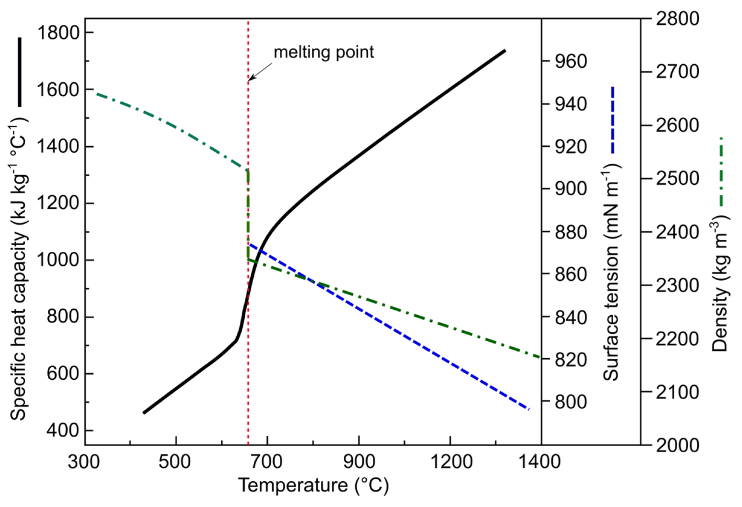
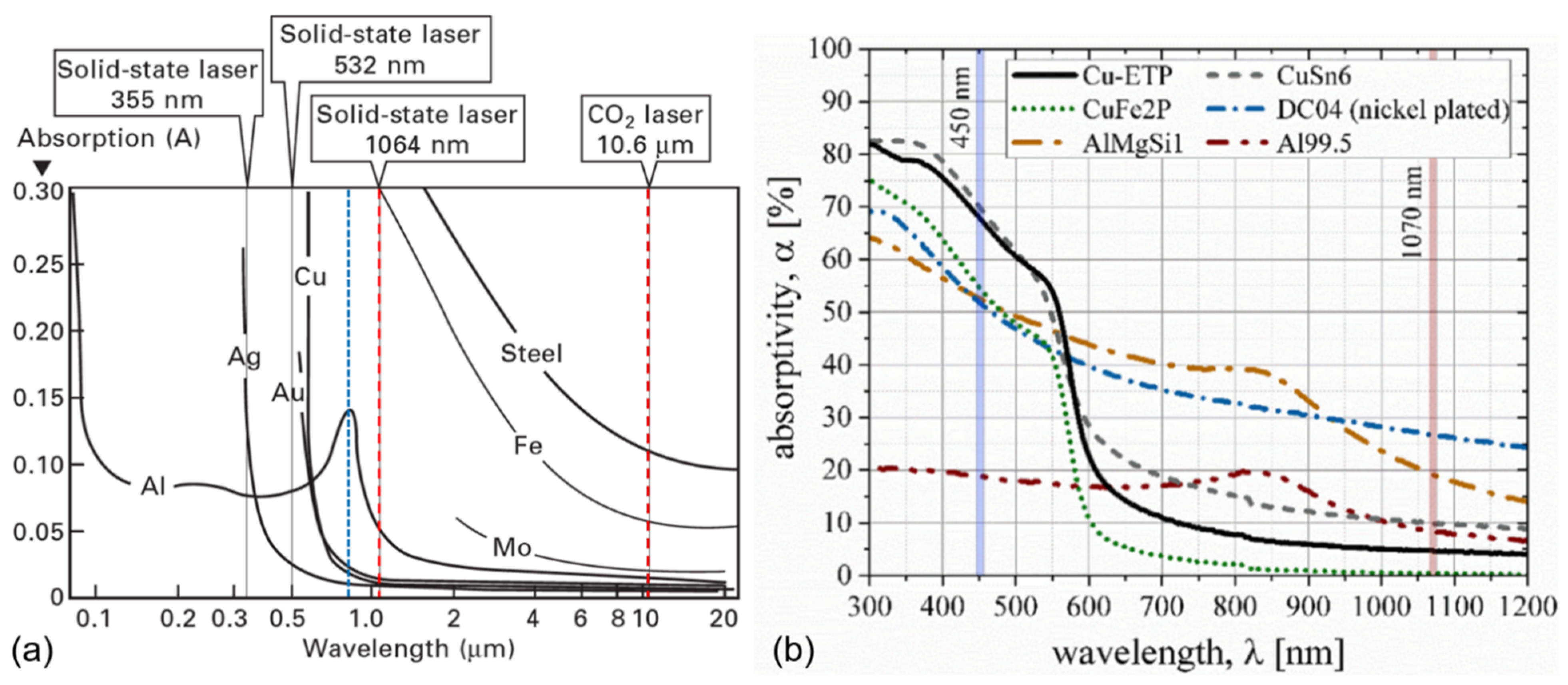
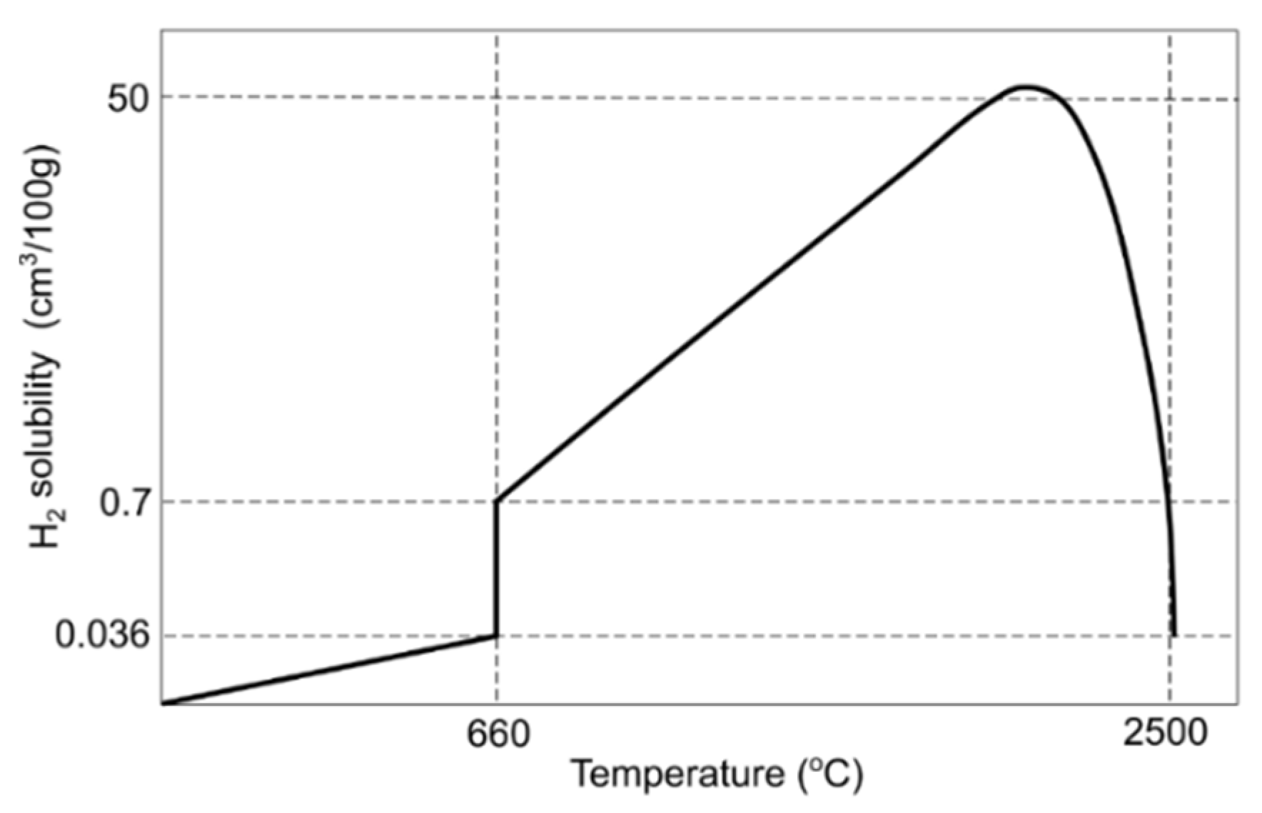
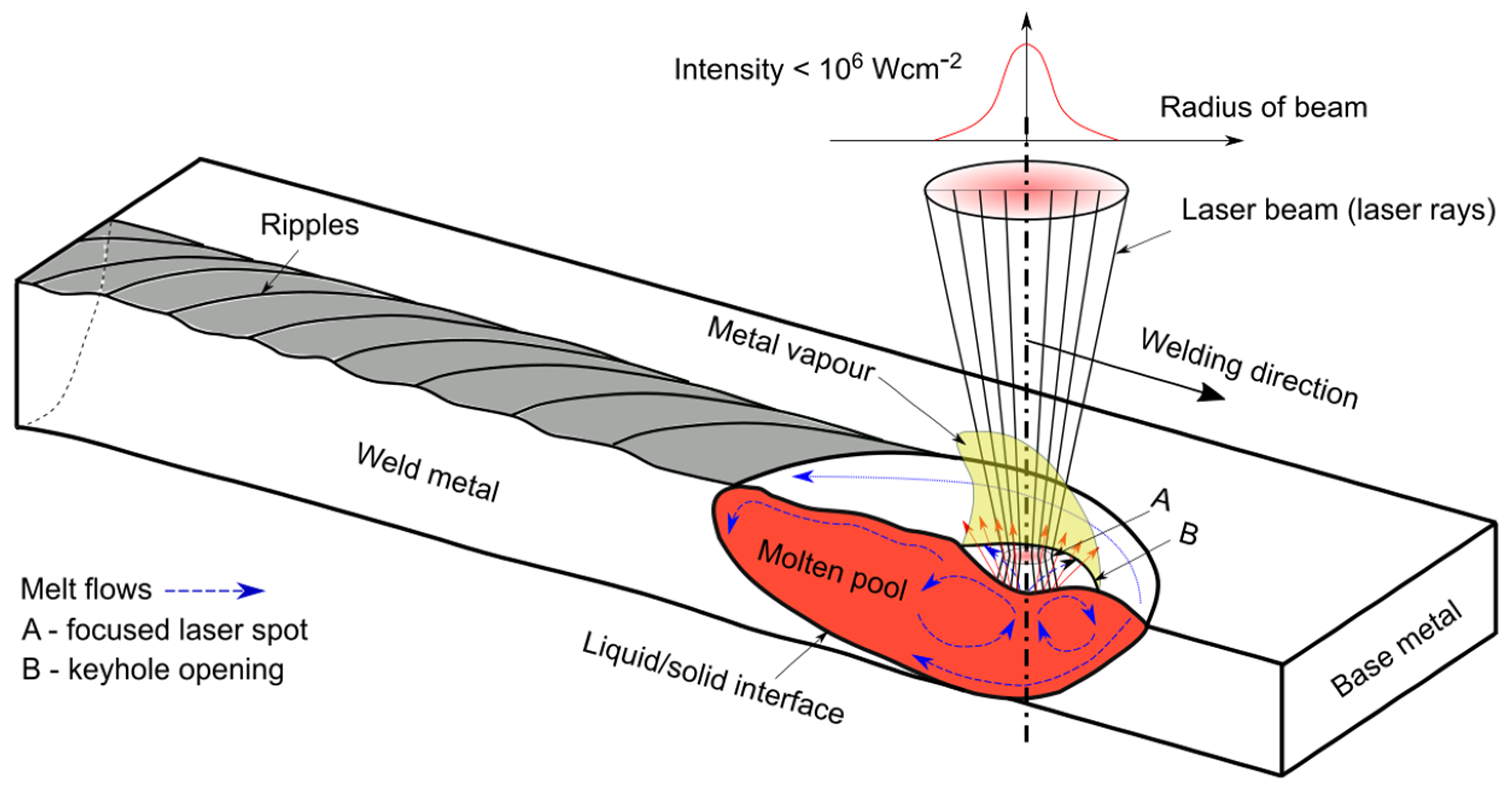
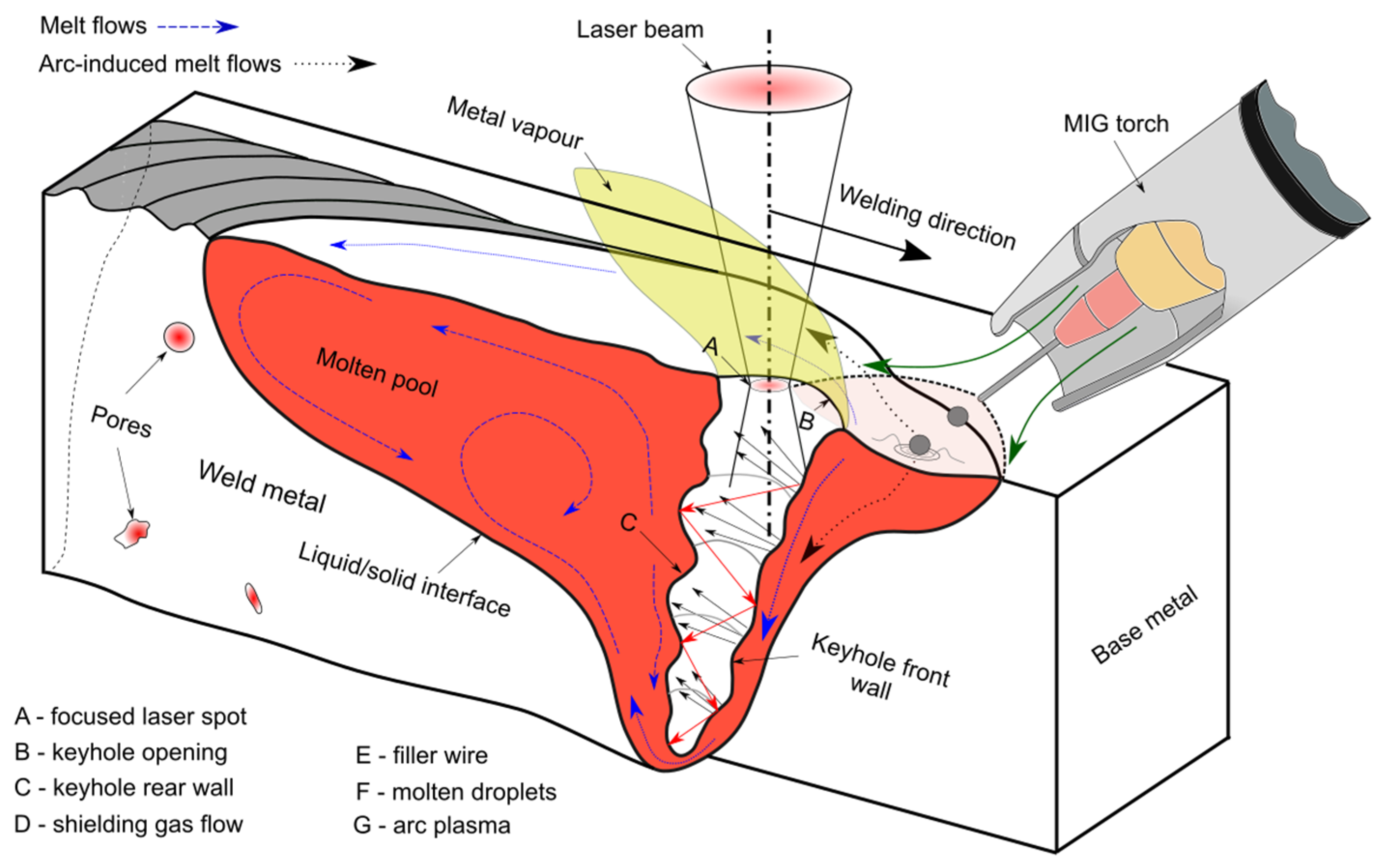
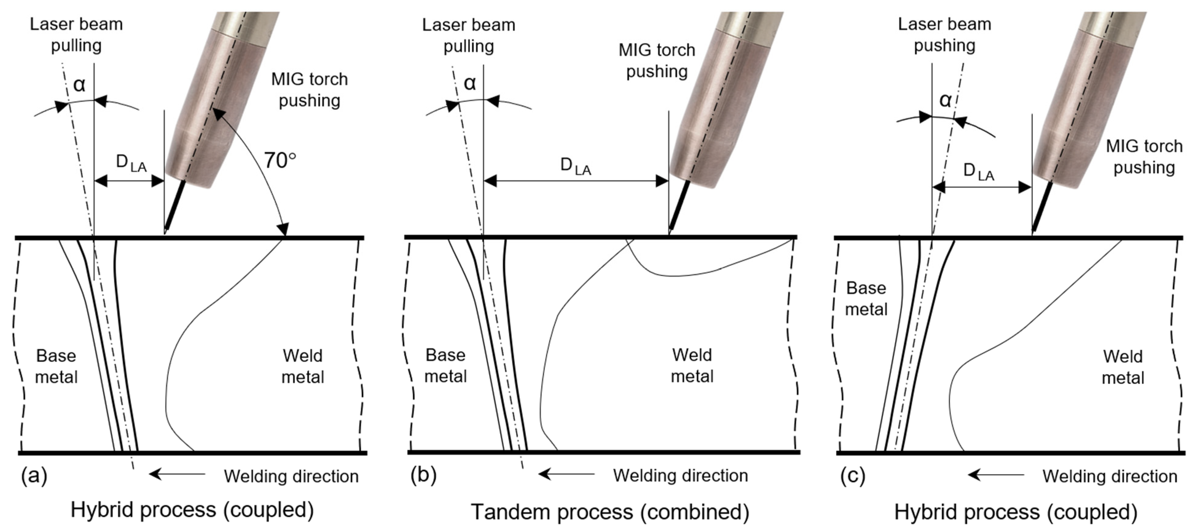
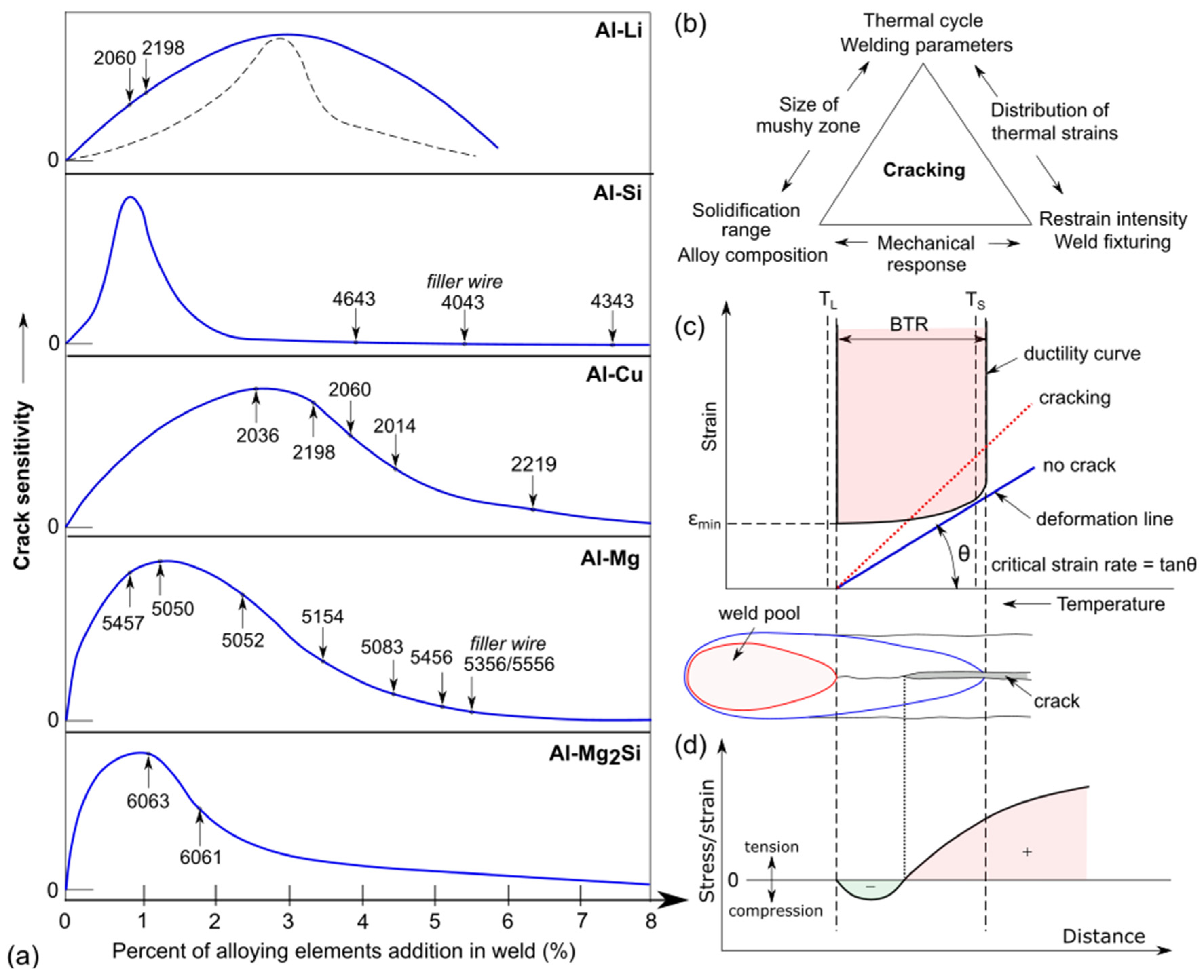
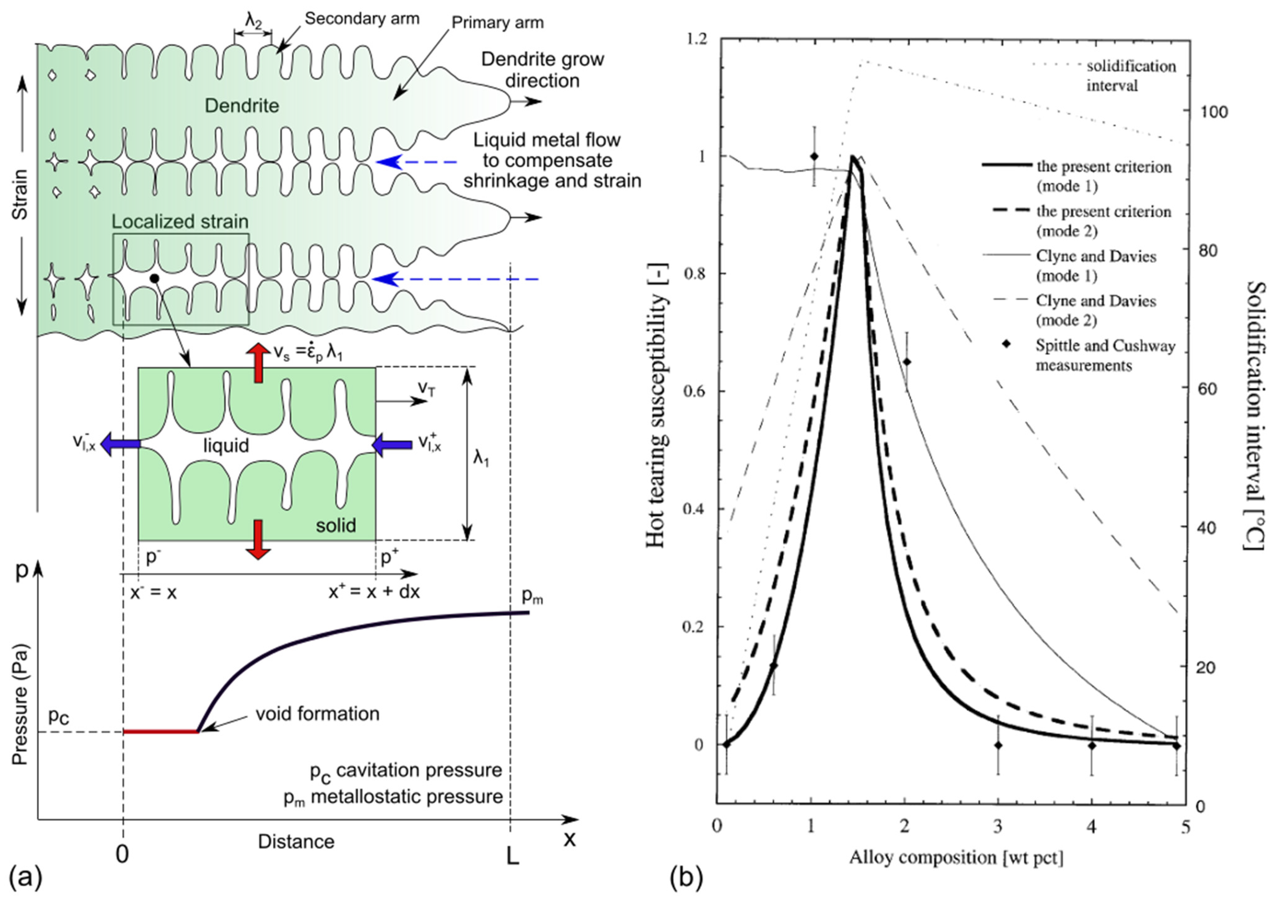
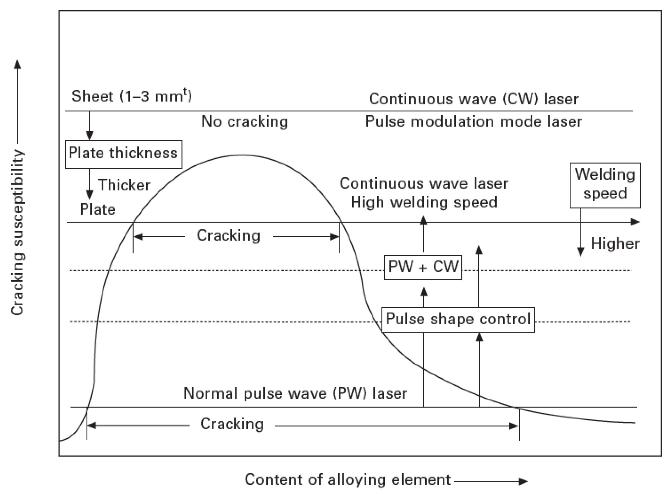
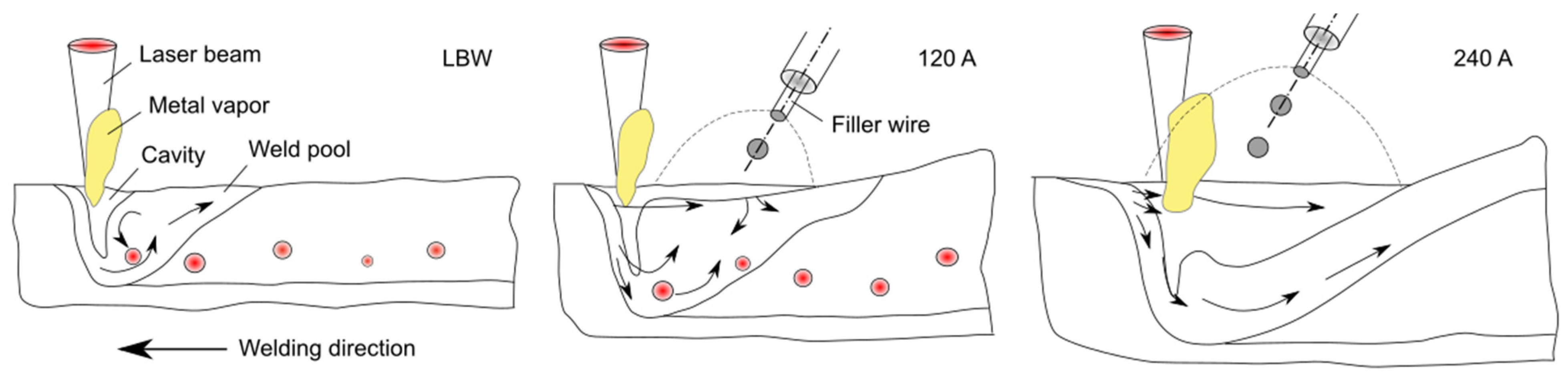
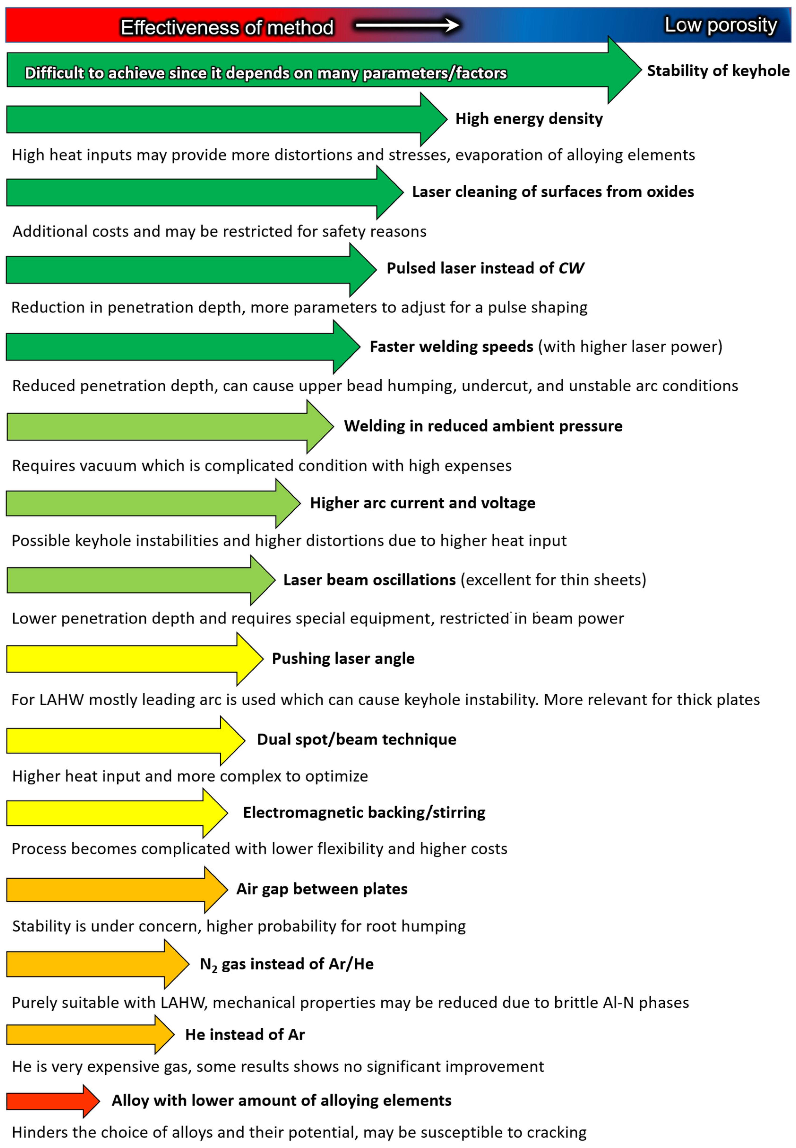
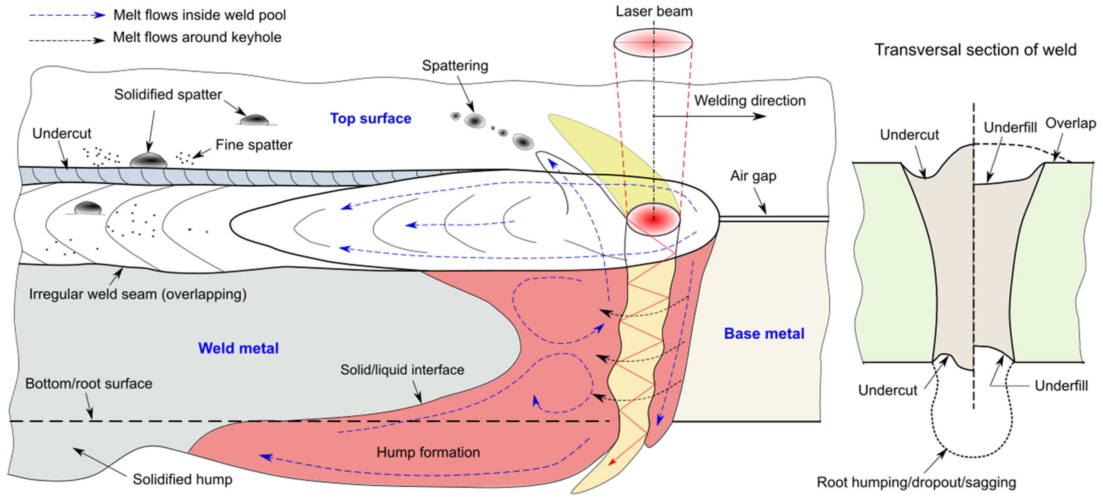
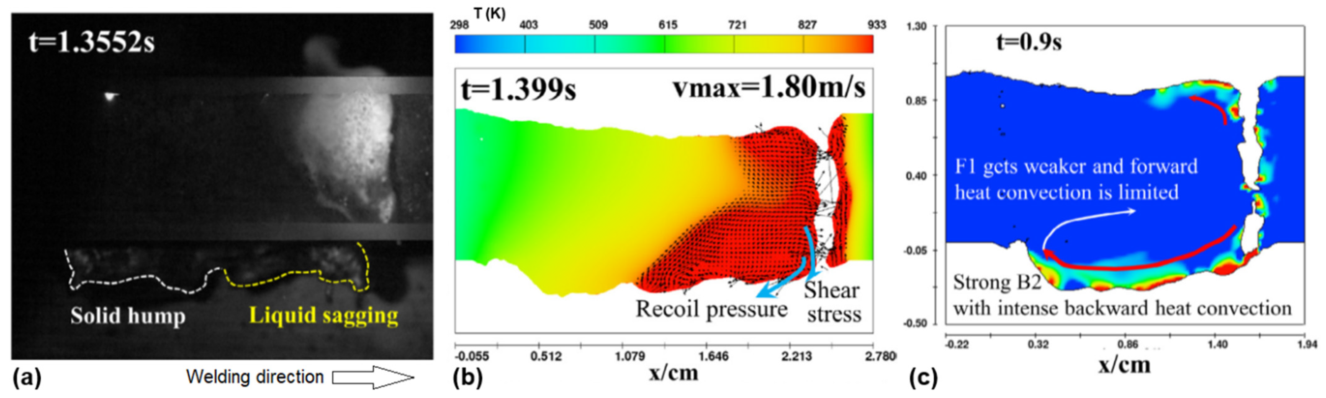
Figure 1. Thermal conductivity changes with temperature of different pure metals. Redrawn from [22].
Metals 11 01150 g001
Figure 2. Thermophysical properties of aluminium. Based on [20].
Metals 11 01150 g002
Figure 3. Absorption coefficient of different metallic materials depending on laser wavelength: (a) wide spectrum, based on [30]; (b) short-wavelength lasers, based on [23].
Metals 11 01150 g003
Figure 4. Hydrogen solubility in Al during welding thermal cycle at 1 atm pressure. Adapted and redrawn from [18,31,32,33].
Metals 11 01150 g004
Figure 5. Schematic drawing of laser beam physics during heat conduction mode with melt flows based on [29,61].
Metals 11 01150 g005
Figure 6. Schematic drawing of (a) laser beam physics in keyhole mode when it is closed from root side, with physics of melt flows are based on [66,67,68,69,70,71,72,73,74,75,76,77,78,79,80,81,82] in case of medium-to-thick sheets (>5 mm); (b) keyhole laser welding for thin plates represents open keyhole in form of catenoid strongly influenced by surface tension forces, based on [42,43,48].
Metals 11 01150 g006
Figure 7. Effect of ambient pressure on size of plasma/weld plume and penetration depth in welding of 30 kW Yb:fiber laser beam of thick Al alloy. After Wang et al. [112].
Metals 11 01150 g007
Figure 8. Representation of LAHW in paraxial configuration with leading laser/trailing arc and their melt flow behaviours. Melt flows are based on [30,38,40,50,59,99,114,115,116,117,118,119,120,121,122,123,124,125,126,127,128,129].
Metals 11 01150 g008
Figure 9. Representation of LAHW in paraxial configuration with leading arc/trailing laser setup and their melt flow behaviours. Melt flows are based on [30,38,40,50,59,99,114,115,116,117,118,119,120,121,122,123,124,125,126,127,128,129].
Metals 11 01150 g009
Figure 10. Process variation according to distance length between laser beam and arc source in case of trailing arc (leading laser) position. (a) Shows hybrid and (b) tandem process with pulling keyhole position, and (c) hybrid process with pushing keyhole position. DLA is the process distance between the laser beam axis and filler wire tip, α is the angle from the laser beam axis to normal and taken as 10°.
Metals 11 01150 g010
Figure 11. Process variation according to distance length between laser beam and arc source in case of leading arc (trailing laser) position. Hybrid process with (a) inclined pulling keyhole position and (b) inclined pushing keyhole position. DLA is the process distance between the laser beam axis and filler wire tip, α is the angle from laser beam axis to normal and taken as 10°.
Metals 11 01150 g011
Figure 12. Typical weld microstructure of AA6061-T6: (a) equiaxed dendrites in fusion zone centre (FZ) [183]; (b) partially melted zone (PMZ) [183]; (c) heat-affected zone (HAZ) with precipitates (dark areas) [183]; and (d) scanning electron microscope image showing columnar dendritic grains growing epitaxially from base metal [184]. Subfigures were modified.
Metals 11 01150 g012
Figure 13. (a) Weld structure of aluminium alloys, modified from [167]. (b) Solidification mode map with influence of various factors adopted for Al alloys [185].
Metals 11 01150 g013
Figure 14. (a) Metallurgical cracking susceptibility based on effect of alloying element and solute concentration, based on [29,30,198]. (b) Factors affecting cracking occurrence [197]. (c) Mechanical cracking susceptibility based on critical strain [197]. (d) Typical distribution of transversal stresses and strains in mushy zone, based on [191,197].
Metals 11 01150 g014
Figure 15. Representation of (a) hot tear formation in columnar dendritic growth with pressure conditions; and (b) the HCS criterion. Based on [190]. Notations: λ1 is primary dendrite arm spacing, λ2 is secondary dendrite arm spacing, vs shrinkage velocity, vl velocity of fluid, vT is solidification rate, and (/dt)p is deformation or plastic strain rate.
Metals 11 01150 g015
Figure 16. Effect of various factors on solidification cracking of LBW of Al alloys, proposed by Prof. Seiji Katayama [30].
Metals 11 01150 g016
Figure 17. The spiking effect phenomenon generating (a) numerical modelling revealing porosities due to keyhole fluctuations and (b) appearance of longitudinal section. Pure Al (99.5%) 2.0 mm thick sheet. After Otto et al. [154].
Metals 11 01150 g017
Figure 18. Effect of welding current on porosity in LAHW of 3 mm AA5052 aluminium based on X-ray transmission during real-time observation. Redrawn from [90,262].
Metals 11 01150 g018
Figure 19. (a) Porosity in LAHW as fatigue initiation point with (b) cracking [282]. (c) Typical microporosity with mixed ductile dimples (no. 1) and brittle quasi-cleavage (no. 2) fracture morphologies using scanning electron microscope [284]. (d) Effect of porosity on ultimate tensile strength (UTS) to base metal ratio in case of autogenous LBW of 3 mm AA5083 showing strong polynomial and linear correlation, modified, and redrawn from [285].
Metals 11 01150 g019
Figure 20. Porosity mitigation mechanisms in LBW/LAHW. Note, ranking is based on effectiveness, costs, and practical use in industry. Below the arrows, the reasons of low overall effectiveness and disadvantages are presented.
Metals 11 01150 g020
Figure 21. Schematic illustration of external imperfection in laser beam keyhole welding during full penetration. Based on [88,164,275,293,294,295,296].
Metals 11 01150 g021
Figure 22. Formation of humping in root in case of 10 mm AA5083: (a) image taken in situ by observation through glass; (b) numerical simulation of hump formation; and (c) thermal fluid behaviour (F1 is forward melt flow and B2 is backward melt flow). Longitudinal weld sideview. After [88].
Metals 11 01150 g022
Figure 23. Hardness distribution in welding of aluminium alloys. Based on [8,18,33,97,100,164,169,174,175,176,177,183,188,195,214,229,256,264,271,282,284,306,307,308,309,310,311,312,313,314,315,316,317,318,319,320,321,322].
Metals 11 01150 g023
Figure 24. Strategy to increase mechanical properties for welding of Al alloys. Note, ranking is based on effectiveness, costs, and practical use for industry.
Metals 11 01150 g024
Table 1. Classification and characteristics of wrought aluminium alloys. Note: most alloys (including 1xxx) have some elements such as Fe, Ti, or Cr in very low amounts (<0.01–0.05 wt.%) as residuals. A-H is age-hardening and S-H is strain-hardening [18,34,35,36].
Property1xxx2xxx3xxx4xxx5xxx6xxx7xxx
Alloying element-Cu, LiMnSiMgMg, SiZn–Mg–Cu
Minor alloying elementsMg, Li Mg, Mn, SiCu, Mg, SiCu, Mg, MnSi, Mn Mn, Zn, Cr, CuMn, Ni
Heat treatment-+---++
Strengthening-A-HS-HA-HS-HA-HA-H
Strengthlowhighlowmoderatemoderatemoderatehigh
Tensile strength, MPa70–175180–480130–280105–350140–410120–380320–620
Corrosion resistanceexcellentmoderatehighhighhighhighmoderate
Weldabilitygoodpoor, crack sensitivegoodgoodmoderatepoor, crack sensitivepoor, crack sensitive
Table 2. Comparison of different common welding methods for aluminium alloys. (Sign representation: + is low level, ++ moderate level, and +++ high level) [30,38,39,40].
Welding MethodProductivityResulting PropertiesPropensity to DefectsCost Investments
MIG+++++(+)Low
TIG+(+)+++Low
LBW++++(+)++High
LAHW+++(+)++(+)++(+)Extra high
Resistance++++Low
FSW+++++Moderate
Table 3. Properties of laser sources used in laser beam welding of aluminium alloys [40,41].
PropertyValueLaser Source
CO2 Nd:YAGYb:Fiber 1DiskHPDL
Wavelengthµm9.4–10.61.0641.0701.0300.78–0.94
Maximum output powerkW20 (fast-axial)81001650
Electrical efficiency%10–153–1030–403035–50
Beam quality 1 (BPP)mm × mrad3–815–254–124–12>50
Spot size 2µm200–600400–60020–500>800>800
Beam delivery-MirrorFiberFiber FiberFiber
Maintenance intervalhours1000<10,000>25,000>25,000>25,000
1 Lower BPP means better laser beam quality with lower divergence. 2 For fiber laser, the spot size may be very small when single mode is used (10–20 µm) and for multi-mode technology, minimum is about 100 µm.
Table 4. Result of laser-arc hybrid welding on porosity formation and resulting strength. MIG source was used. References compiled in chronological sequence.
Alloyt, mmTechniqueLaser Type, kWPreferable Arc Position: CommentsEfficiencyReference
60612.0Single-sidedNd:YAG, 3.0 Leading arc: had lower porosity at top of bead with DLA = 1.0–3.0 mm 1N/ALee and Park [113]
50523.0Single-sidedNd:YAG, 3.1 Trailing arc: shallower and wider welds with more stable weld pool improved degassing of bubblesN/AKatayama et al. [90]
57543.0Single-sidedFiber, 3.0-3.5 Trailing arc: lower porosity due to better stability, TIG was used.N/ACasalino et al. [271]
50835.0Single-sidedFiber, 2.5Trailing arc: provided significant less pores with DLA > 1.0 mm~70% 2Bunaziv et al. [228]
508310 Double-sidedFiber, 4.9Trailing arc: less porosity due to more stable process (based on A/V waveforms) and wider weld pool more time for bubbles to escape90%Huang et al. [272]
508330Double-sidedFiber, 10Trailing arc: slightly less porosity due to improved stability N/AJiang et al. [273]
1 not clearly specified but photo images were provided. 2 incomplete penetration welds.
Table 5. Overview of results achieved in LBW and LAHW of Al alloys. Here, Eff. means WM to BM strength ratio in %, (aw—means as welded condition, pw—post-weld heat treatment).
Alloy (Thickness in mm)WireEff.Results
2xxx series, Al–Cu alloys
2A12 (8.0) 2319 (Cu ~6 wt.%)78Defect-free welds in CO2 laser-MIG hybrid welding. Segregation of Cu/Si-rich precipitates on grain boundaries and in interdendritic areas resulting in intergranular fracture. The wire provided more Cu for formation of precipitates, resulting in higher strength. As a result, finer distribution of precipitates by controlling welding parameters should be adopted in combination with Cu-alloyed filler wire. Yan et al. [332]
2024-T3 (3.0)404386Fiber laser-MIG hybrid welding of butt joints with different He–Ar shielding gas combinations. He-rich shielding gas provided wider welds with lower undercut and underfill. HAZ softened by ~15–20% due to the coarsening and dissolution of secondary phases by slow cooling rate. Weld metal strength was reduced by ~30% due to evaporation of Mg and larger grain size. Some porosity and cracking were observed. Use of 4043 filler wire slightly increased the strength (86% eff.) by reducing the crack sensitivity. However, elongation with and without filler reached only 24%, 14.9% for BM, and 3.7% for weld, respectively. Further optimisation of parameters yielded improvement in reducing crack sensitivity and stability by combination of a slightly defocused laser, lower welding speed, and lower heat input from laser beam. Ahn et al. [311,312,333]
AA2219-O (2.0)none>100 pw A combination of PWHT and EM pulse treatment was applied after fiber laser. This treatment which reduced the presence of eutectic phases and promoted precipitation strengthening by dispersoids formation, i.e., G.P(II) zone and metastable θʺ phase (Al2Cu). Higher hardness than in the BM was observed. Tensile strength of 393 MPa after PWHT was achieved, while the corresponding BM strength was 153 MPa, i.e., an increase of 258% in strength was found. After EM treatment, it was raised to 303%. However, the ductility (reduction of area after tensile testing) was reduced from 33% in the BM to 10% as-welded condition. Ductility was slightly restored to 18% after PWHT, but down to 9–11% after EM treatment. Zhu et al. [334]
2xxx series, Al–Cu–Li alloys
AA2060-T8 (2.0)508763Fiber LBW provided poor reprecipitation due to fast cooling rate. HAZ and WM had reduced hardness by the factor of two compared to BM. In interdendritic and intergranular zones, high segregation of Cu, Mg, and Li solutes was observed. In the further work, high strength eff. of 83% was achieved by use of AlSi12 filler wire were WM was strengthened by LiAlSi phases in addition to Al2Cu and some Mg2Si. However, high hardness losses still presented in WM. Zhang et al. [174,308]
AlSi1283
2060-T8/2099-T83 6 wt.% Cu 80Fiber LBW of double-sided T-joints produced high strength welds due to low porosity and favourable microstructure by filler wire with high Cu content instead of 4047 with high Si. Wire provided Al6–CuLi3 phases between grains providing low hot cracking susceptibility. Han et al. [335]
2A97-T4 (2.0)none83Autogenous fiber LBW, butt joints. Losses in strength were associated to low tendency to re-precipitation which caused softening in WM and partly in HAZ, and segregation of Cu on grain boundaries. Fu et al. [177]
5xxx series, Al–Mg alloys
AA5083-H111 (4.0)ER535685 Fiber laser-MIG hybrid welding provided lower softening in HAZ and WM compared to MIG. The HAZ width was twice as narrow. Tensile strength was slightly better than MIG. Fatigue was improved but failed due to porosity. Yan et al. [282]
AA5083-H111 (10)ER5183 90Fiber laser-MIG hybrid welding provided softening in WM and HAZ was achieved. For leading laser setup due to more uniformly dispersed Al6(Mn,Fe) secondary phases with higher density of dislocations. Huang et al. [272]
AA5754 (3.0)ER535682 aw, 98 pwFiber laser-MIG provided 82% in as welded condition. After PWHT at 35 °C for 50 min, eff. increased to 98% close to BM with UTS of 244 MPa, since softening was eliminated by reduction of segregation and restoration of Mg solution strengthening mechanism. Leo et al. [314]
5A06-H112 (8.0)none90%Infinity shaped oscillations (∞) with fiber LBW reduced porosity from 40% down to 2%. At the same time ductility (elongation) was also substantial reaching 90% of BM. However, oscillations significantly reduced penetration depth with change from keyhole towards transition mode. Wang et al. [316]
5A06 (35) none90% Welding in subatmospheric pressure increased mechanical properties of deep welds due to higher retained hardness in fusion zone, lower porosity, lower evaporation of Mg, and more uniform grain distribution. As a result, welds made at 10 Pa ambient pressure, provided 90% strength eff. compared to welds made at 1 atm with 73% eff. Peng et al. [171]
6xxx series, Al–Mg–Si alloys
AA6013-T4/T6Al12Si 75 aw, 90 pwNd:YAG LBW was used for butt joints with different atomised powders as filler material. No cracking was observed on macro-level. In as-welded condition for WM regardless tempering condition, similar hardness was produced with softening (T6 for BM had 140 HV) except the weld with application of AlSi12Mg5 powder. Hardness was increasing with increase of Si with Mg content. Applied PWHT to T6 condition significantly restored low hardness in FZ but for WM low hardness remained. Restoration after PWHT in WM was associated with precipitation strengthening in α-Al dendrite cores having needle-shaped β" and Q’ phases, aligned along <100> direction due to Mg and Si enrichment from filler powder. In interdendritic area, residual elements (Fe, Cu) were observed which are harmful for mechanical properties. Most optimum filler materials found was Al12Si compared to filler powders containing Si with Zr, Mn, and Cr. Braun [100]
AA6005-T5 (5.0) 5356 74Fiber laser-MIG showed better results than MIG. Decrease in efficiency was attributed to WM and HAZ softening (hardness reduced by 15%), porosity, larger grain size than BM, and losses of alloying elements (Mg, Mn) due to keyhole regime but lower than in MIG. Moreover, LAHW provided a twice as narrow HAZ with lower decrease in hardness compared to MIG. Yan et al. [166]
AA6082-T6 (8)5087 80 awFiber laser-MIG hybrid welding of butt joints produced equiaxed dendrites in centre of WM were achieved which were twice smaller compared to only MIG, 96 μm and 50 μm, respectively. Mg2Si phases re-precipitated due to faster cooling rate in LBW. Decrease in strength was associated with large pores in WM and coarsened precipitates to size of 0.5–1.0 μm. Zhang et al. [336]
AA6061-T6 (4)ER404380 pwLAHW of butt joints using ER4043 filler wire provided higher strength due to smaller grain size with reprecipitation but lower fatigue due to microporosity and their density than ER5356 filler wire. Yan et al. [281]
AA6061-T6 (3)ER536587 pwFiber laser-TIG was used for butt provided high strength after PWHT (at 520 °C for 1 h) due to fine (nano-level) reprecipitation of β" phase with uniform distribution. Wang et al. [183]
7xxx series, Al–Zn–Mg–Cu alloys
AA7075-T6 (2.0) 231985 pwArtificial ageing after Nd:YAG laser-MIG hybrid welding (at 120 °C for 24 h) provided the strength comparable to BM. Significant softening was obtained in as-welded condition. Natural aging (3 weeks) compared to 10-day artificial ageing had no significant improvement in strength. Alloying elements were mainly redistributed in dendritic structure along grains boundaries (element segregation) with depletion inside dendrite branches regardless type of PWHT. Hu and Richardson [337]
AA7075-T651 (6.3)ER404385 pwYb:YAG laser-MIG provided much less HAZ cracking than LBW with cold wire due to higher heat input causing less tensile stresses on cooling. High cracking susceptibility in HAZ was noted. Natural aging (5 weeks) restored hardness and strength was improved to 85% from that found in BM. Ola and Doern [195]
Al-Zn-Mg-Cu alloy T6 (2.0 mm) with 0.23 wt.% Zr and 0.14 wt.% Ernone70 pwAfter fiber LBW of butt joints, significant softening in WM and in HAZ closer to BM was achieved providing 70% strength eff. after 7–60 days of PWHT. Relatively small grains were only achieved near the fusion line, but the WM centre consisted of equiaxed dendrites with larger grain size similar to BM. A strong segregation of alloying element along grain boundaries was observed forming brittle T-phases consisting of Al2Mg3Zn3. As a result, the matrix in WM had a lack of Zn and Mg, which caused softening. This shows that delicate balance between heat input and response of alloying elements must be taken into consideration making these alloys very hard to weld. Zhang et al. [306]
AA7xxx (12.7)555660Fiber laser-MIG was used for I-groove butt joints. LAHW provided level B quality [187] with 0.3% porosity due to cleaning parent material and use of low moisture shielding gas. Novel filler wire provided very fine grains with increased mechanical properties. However, the tensile strength and elongation (the parameter of ductility) of the hybrid weld metal were slightly lower than welds made by autogenous LBW. Weld metal was least ductile zone due to unfavourable microstructure including severe microsegregation and formation of interdendritic eutectic films. Allen et al. [338]
Dissimilar Al alloys
AA7050 (2.0)/ AA2023 (2.0) 4047 90 Fiber laser welding of T-joint. Helium as shielding gas was used for porosity suppression by lowering melt viscosity with improved degassing. It seems the authors in subsequent works changed towards Ar as much more cost-efficient shielding gas with similar quality of joints. Efficiency of 90% eff. was achieved due to softening in welded zone and HAZ. Enz et al. [339]
AA6156 (3.0)/ AA2139 (2.7) 4047 100 pwNd:YAG laser welding of T-joint. Slight softening in HAZ. It was characterized by favourable strains distribution after welding in BM, not in softer HAZ. Viscusi et al. [340]
AA7075/ AA5182-O (2.0)none60Nd:YAG LBW was used for butt joints and larger beam diameter (0.8 mm as focused) resulted in larger weld pool with improved degassing and low hydrogen (2 ppm). AA7075-T6 had softening while AA5182-O had similar hardness in both WM and HAZ as BM. PWHT to T6 condition greatly restored hardness similar to BM. Strength eff. was high of 118% in term of 5182-O BM but much lower for 7075-T6 BM case, 60% eff., due to high initial strength of base metal. Fracture occurred in BM of 5181 alloy, otherwise fracture occurs in fusion zone due to discontinuities (undercut/underfills). Enz et al. [341]
Publisher’s Note: MDPI stays neutral with regard to jurisdictional claims in published maps and institutional affiliations.

