Review

Tribological, Corrosion, and Mechanical Properties of Selective Laser Melted Steel

Department of Mechanical Engineering, University of Nevada Reno, Reno, NV 89557, USA
*
Author to whom correspondence should be addressed.
Metals 2022, 12(10), 1732; https://doi.org/10.3390/met12101732
Submission received: 21 September 2022 / Revised: 8 October 2022 / Accepted: 8 October 2022 / Published: 16 October 2022

Abstract

:
In additive manufacturing (AM), selective laser melting (SLM) is a relatively novel technique that utilizes thermal energy via laser beams to melt and solidify metallic powders into three-dimensional components. Compared to traditional manufacturing techniques, SLM is advantageous because it is more time-efficient, cost-effective, and allows for the fabrication of components with superior mechanical, tribological, and corrosion performances. However, much of the existing literature highlights the influence of SLM on softer materials such as aluminum or magnesium due to their thermal expansion coefficients rather than on materials such as steel. This review aims to encapsulate the existing literature on SLM steel and understand the factors that allow for its fabrication and the underlying mechanisms that dictate its mechanical, tribological, and corrosion performance. By understanding the trends of laser energy density (LED), scanning patterns, and building directions for these properties, a comprehensive understanding of SLM steel can be achieved. Additionally, through this understanding, the future directions of this research and suggestions will be provided to continue progressing the field in an impactful direction.

1. Introduction

With the recent emergence of the fourth industrial revolution (also commonly referred to as Industry 4.0) and the innovation of additive layer-by-layer based manufacturing systems has largely revolutionized the approach to part fabrication [1]. Acting as one of the key enablers of Industry 4.0, the elimination of reliance on subtractive techniques (e.g., drilling, milling, broaching, etc.) enables a new direction that manufacturers can use to rapidly fabricate robust and reliable components [2]. As such, the potential cost savings for rapid-part manufacturing is immense, as factors such as the energy consumption of post-subtractive techniques, the shipment of traditionally manufactured equipment, and the lead time of traditionally manufactured components can be quite costly [3]. In fact, due to these advantages, the attention toward additive manufacturing (AM) has exponentially been increasing. It has been predicted that the market will be worth $32 billion by 2025 and nearly $60 billion by 2030 [4]. Out of the existing AM market, laser-based AM techniques such as direct laser metal sintering (SMLS), laser metal deposition (LMD), and selective laser melting (SLM) have attracted much attention in recent years (with the exception of non-beam processes such as micro-stereolithography (MSL) [5,6]. Of the aforementioned technologies, SLM has gathered the greatest amount of attention due to its ability to fabricate a wide variety of materials spanning from ferrous to non-ferrous alloys [7]. As such, their mechanical, tribological, and corrosion properties can be effectively tailored [8,9,10]. However, to understand the importance of SLM, it’s critical to understand its fabrication mechanisms and implications for industrial applications. To elucidate, selective laser melting (SLM) is an AM process that creates three-dimensional (3D) parts in a layer-by-layer fashion. This is achieved by using a high-energy laser beam to melt and consolidate the specified metal powder selectively [6]. Since its conception in 1997, SLM has operated by following a two-dimensional (2D) outline with a high-intensity laser along a powder bed. The 2D outlines are composed of slices of a 3D computer-aided design (CAD) model. These slices are created by computer-aided manufacturing (CAM), which defines the surface geometry of the 3D CAD model to determine the laser scanning path needed to produce the part.
To further visualize the process, Figure 1 demonstrates the general concept of SLM. An even layer of metallic powder is dispersed onto the melting bed of which a shielding inert gas (typically composed of argon, helium, and/or nitrogen [11,12,13]) is deposited to prevent oxidation. In the case of oxidation, undesirable defects such as cracking or porosity can occur [14]. Once the encased environment is filled with the shielding gas, the bed is then subjected to a laser beam that scans the path of an individual layer produced by a CAM software. The laser beam quickly melts the powder, solidifying it to produce one physical layer of the 3D build. As the powder cools, the supporting piston of the melting bed is lowered, allowing the bed to be refilled by a roller; this process repeats until the part is fully manufactured. Once the part is manufactured, the piston supporting the build platform extends until it is flush with the machine’s tabletop, allowing the user to remove the excess powder with a brush or a vacuum to repurpose the leftover metal powder. By doing so, the user exposes the completed part. Part removal from the build plate is performed manually with a bandsaw or with a wire electrical discharge machine (EDM) [15].
The freedom to manufacture complex and intricate designs with SLM allows for great flexibility for various industrial components, such as customized medical implants, integration of cooling channels into a design, and lightweight parts for automotive and aerospace applications [16]. Due to the additive nature of this process, there are many advantages compared to traditional manufacturing techniques, as shown in Table 1. Similarly, when compared to other AM techniques such as fused deposition modeling (FDM), direct energy deposition (DED), VAT polymerization (VAT-P), and many more [17,18,19,20,21,22], SLM is much more time-efficient and cost-effective due to its ability to use metals as the constituent for near-net shaped manufactured parts [23,24,25].
With the use of metals as an AM material, SLM parts are becoming increasingly desirable in the aerospace, automotive, and biomedical industries [27,34]. In addition, SLM provides a greater opportunity for part optimization by controlling the parameters of the melting process as well as adding composite mixtures that can influence thermal conductivity by decreasing porosity to enhance the evaporative heat transfer [35]. The parametrization of laser power, laser scanning speed, and hatch spacing pioneers the ability to create a lightweight component with tight-tolerance dimensions and desirable mechanical properties for industrial applications. Hence, SLM is advantageous because minimal preparation is needed to produce a strong and functional part [36].
SLM is in demand within the aerospace sector since it can provide tight dimensional tolerances, lighter components, and optimal mechanical properties necessary for extreme conditions where the parts are exposed [37]. Additionally, SLM manufacturing can construct complete thrust chambers and heat exchangers as a single unit without needing to connect components [38,39]. In contrast, traditional manufacturing techniques such as casting and milling demand more preparation and development to understand the effects of post-assembly processes such as welding, fastening, or binding [6]. The automotive field also presents a great opportunity for SLM as this process can create small- to medium-sized lightweight parts that can act as prototypes for the developmental process [30,40,41]. From a broader perspective, the lead time to manufacture these types of components is drastically reduced, which has been reported to compensate for high demand, production safety, handling, reduced waste, recycling ease, and saving energy [31,42,43]. Through SLM, the lead time and costs needed to manufacture highly complex components can outweigh the high-speed machining [44].
Compared to the production of tool inserts via laminated steel, SLM can reduce production time by upwards of 260 h [45]. Prosthesis manufacturing can also benefit greatly from SLM technologies. For example, a dental crown or an above-knee leg prosthetic—can be uniquely manufactured to fit the patient’s body [46]. Moreover, precision manufacturing allows SLM to drastically improve the biocompatibility of prostheses through manufacturing techniques that mimic bone structure while providing the same rigidity and stiffness of bones. SLM can produce intricate geometries that are too complex with traditional manufacturing techniques, even allowing the implementation of sub-mm features [47].
Understanding these points, in SLM, softer metals such as aluminum, magnesium, and copper allow for a proper, dense solidification of the final build due to their thermal expansion properties [41]. In contrast, steel has a lower thermal expansion with a high-temperature range, resulting in a high laser energy density to melt the powder [48]. The high-temperature treatment and fast cooling of steel during SLM manufacturing increase the strength of steel, reduce wear, and improve corrosion-resistant properties [49,50,51]. Harder metals such as steel tend not to be as widely investigated for SLM operations as there is yet to exist a comprehensive understanding of the formation mechanisms. Given the large number of applications for which steel can be used (e.g., in biomedical, automotive, and aerospace [15,52,53,54,55]), there is an increasing need to expand the knowledge about SLM of steel components. This review aims to provide a comprehensive discussion on the mechanical, tribological, and corrosive properties of steel throughout the entire SLM process, from setting up the powder fusion bed to the post-processing needed to create a functional part. Considering all of the existing literature to this point, a comprehensive review of SLM for steel and its alloys has not been performed; hence, this research paper aims to provide a collection of information to incentivize the use of SLM steel, detailing benefits as well as shortcomings that can be improved through further research. Since steel is prevalent in the aerospace, military, automotive, and biomedical fields, the SLM process can not only improve the physical properties of steel compared to traditional parts. Still, it can also incentivize the use of steel for prototyping and can reduce costs for low-quantity, high-precision production assignments [56].

2. Structural Mechanisms

In SLM, many complex processes simultaneously occur (due to the influence of the laser energy density (LED)) that allow for the fabrication of the final build. Considering that steel components are compositionally different from other softer metals such as aluminum and magnesium, it can also be insinuated that the key variables enabling the mechanisms of steel will differ. Generally, when steel is subjected to the SLM process, rapid solidification conditions occur [57]. These rapid solidification conditions occur during the SLM process due to the high-temperature gradients along the solid-state and liquid-face interfaces in the form of melt pools. The melt pools will then rapidly solidify, thus creating the final part [58]. When the localized melted region experiences high-temperature gradients, the final microstructural elements are much finer than those with lower thermal gradients due to the crystal growth limitation [59]. However, when the thermal gradients are too high, the thermal stresses in part are often greater. These thermal stresses can lead to cracking, premature failure, and geometrical deformations [60]. These rapid solidification conditions can also often lead to the steel having microstructures with many low-angle grain boundaries [61]. Because of this factor, the microstructures have many geometrically necessary dislocations (GED) enabled by the strain energy induced from laser melting. These geometrically necessary dislocations largely depend on the amount of stored energy and the local strain gradients from the dissipated thermal energy. One factor that can affect the recrystallization process (which affects the cell size and solute segregation along the cell boundaries) is the laser scanning speed. According to Gao et al. [62], scanning speeds at 800 mm/s can allow for a faster solidification rate, which results in finer cells and a higher solute trapping at the grain boundaries. This is due to the impediment of the recrystallization process, as lower scanning speeds (i.e., 400 mm/s and 600 mm/s) have longer cooling times.
Compared to traditionally cast steel, the grain structure of SLM-manufactured steel is largely different. In a study by Alnajjar et al. [63], the microstructure of SLM’ed 17-4 PH steel was compared with conventionally produced wrought 17–4 PH steel. The wrought steel was heat treated at 1050 °C for 1 h and water quenched immediately after. In an argon-filled chamber, the SLM steel was made into cylinders horizontally and then machined into tensile specimens before being heat treated and water quenched under the same conditions. Conventionally produced wrought is typically found to have a martensitic microstructure due to the transformation of δ-ferrite to austenite (from heat treatment) to martensite (due to cooling). However, unlike wrought steel, the SLM’ed steel was found to have no evidence of a martensite-like microstructure. This was largely due to the extremely high cooling rates of the SLM process (being at 105 K/s–106 K/s), as it limits the δ ferrite to γ austenite transformation. As such, the δ-ferrite is thermodynamically stable. Similar findings were also reported in the separate work of Alnajjar et al. [64]. To add, the grain structures were also lengthened along the build direction of the piece, creating an anisotropic microstructure (due to the direction of the thermal heating). The SLM’ed 17–4 PH steel was also shown to have a homogenous distribution of alloying elements present in the grains and was also found to have no segregation due to the high cooling rates present. The high cooling rate causes the solid-state interface and the liquid-state interface to become stable, allowing the solidification to produce solute trapping and no diffusion.
Understanding these concepts, it can be insinuated that the influence of laser parameters can largely dictate the formation and metallurgical mechanisms of SLM’ed steel. In particular, these laser parameters constitute a variable known as laser energy density (LED). This process is described by the following:
E d = P e f f v s h d
where E d is the energy density (J/mm3), P e f f is the effective laser power (W), v s is the effective laser scan speed (mm s−1), h is the hatch distance (mm), and d is the powder bed layer thickness (mm) [65].
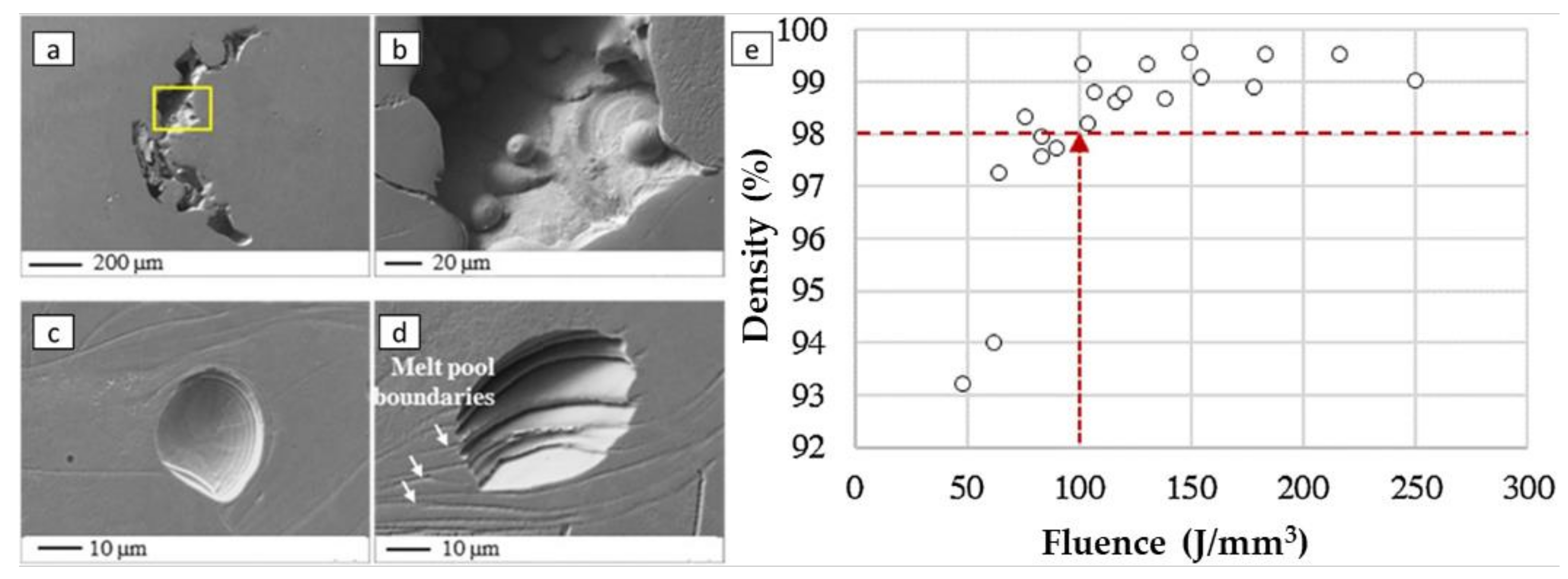
These laser parameters largely determine the temperature gradient during the SLM, which can largely dictate the formation mechanisms along the surface. The balance of the cooling rate to the localized heat flow largely dictates the grain orientation, size, and morphology alongside the fusion of particles [66]. Similarly, the laser parameters also affect the density of the final product [67]. One such parameter that has been reported to influence the final build is layer thickness. With greater layer thicknesses, the degree of effective particle bonding from the melt zone decreases, resulting in a non-robust build. Likewise, having too thin of a layer thickness can result in localized vaporization, thus resulting in unwanted vapor recoil and warping the melt zone. According to the work of Spierings and Levy [68] and Abd-Elghany and Bourell [69], the minimum effective layer thickness of SLM steel parts is 30 μm. Of course, this factor is largely dependent on the laser scanning speed and laser power, as they are the two most impactful parameters that affect the quality of the final build [38]. It has been reported that if the process has too high of a scanning speed or too low of a laser power (i.e., having a lower LED), the end product is very porous due to insufficient thermal heating [70]. This is largely due to the degree of thermal heating, as it tends not to be sufficient for complete particle fusion due to its low fluidity [15]. However, when the LED is increased to a sufficient quantity, the melt pool can sufficiently fuse with the surrounding region and solidify into a relatively dense component. In fact, for 316L SS, Liverani et al. [38] found that when the LED is less than 100 J/mm3 (with laser power, scanning speed, and hatch space of 100 W, 700 mm/s, and 0.07 mm), the part density was measured at around ~98.0%. The defects were largely attributed to layering voids, gas entrapment, and binding defects, which were rooted in insufficient laser energy during the laser process.
Similarly, balling was observed along the molten track. In the presence of balling, the melted particles take a spherical shape while maintaining a highly viscous form. Their surface energy decreases, thus decreasing their wettability, which results in uneven melting along the surface. However, when the LED is between 100 J/mm3 and 200 J/mm3, a part density as high as ~99.6% (at an LED of 159 J/mm3) was achieved, thus insinuating that a sufficient degree of melting and solidification was achieved. Past 200 J/mm3, the porosity decreases slightly (at ~99.1%). Likely, this was attributed to potential vaporization due to the excess thermal heat along the surface. To further visualize this work, the LED, as a function of porosity and the defects found, is shown in Figure 2.
Huang et al. [71] also optimized the LED to obtain a relatively dense build for maraging steel 18Ni-300. In their work, a four-factor (consisting of laser power, scanning speed, powder thickness, and scanning spacing) and four-level orthogonal experimental design were applied to study the influence of LED (which was varied between ~25 and ~225 J/mm3) on the part density. It was found that among all of the tested variables, laser power was the most influential factor needed to achieve a high-part density. Similar to the aforementioned work, this is largely due to the influence of the laser affecting the powder’s fluidity during melting. This was similar to the second most important laser parameter, scanning spacing. Interestingly, as aforementioned, it is typically reported that the scanning speed has a greater influence on the porosity of an SLM build. However, in this case, the scanning spacing can affect the porosity due to the overlap rate from each scanned direction. If the scanning spacing is too small (i.e., >0.08 mm), a gap can form along the adjacent metal channels, increasing the localized porosity. An optimized layer is formed between 0.08 mm and 0.11 mm due to the flat overlap of the melted regions (as the two melted tracks are not intensively interacted). Past 0.11 mm, the gap becomes too large, which causes unevenness throughout the melted region. The scanning speed was found to be the third most influential parameter after this parameter. When the scanning speed was too high, the particles were insufficiently melted, which caused a higher degree of porosity. If set too low, the localized powder will vaporize due to overburning, which can cause a porous type of defect. Lastly, powder thickness was the last most influential parameter for dense build fabrication. This was largely attributed to the energy needed to melt the layer sufficiently. The laser energy is insufficient for thicker layers (>0.05 mm) to completely melt the entire layer. As such, voids are formed along the surface. However, thicker part densities can be achieved when layers of a lower thickness (<0.05 mm) are introduced.
When discussing the formation of porosity, the scanning direction and mode of laser application (i.e., pulse or continuous laser) are factors that can influence the final builds for steels. This was elucidated in the work of Qiu et al. [72], where a pulsed laser was used to form three builds (using 316L SS) of different scanning directions. These scanning directions consisted of the following:
  • Meander: Applying a bi-directional laser scan at a 45° angle from the normal part direction;
  • Stripes: Various sections of columnar shape along the build surface were fabricated using a bi-directional laser scan;
  • Chessboard: Various rectangular sections of the build interface were formed using a bi-directional laser scan strategy. Each rectangular section was rotated by 90°.
In this work, it was conspicuously observed that the porosity of the parts did not differ significantly when using different scanning patterns in this experiment. However, it should be expected that some change would be present due to the cooling rates of the scanning directions. However, when the laser intensity was varied, the area fraction of porosity was changed as expected. A parabolic-like trend of porosity to laser power (from 110 W to 200 W) was found, with the laser power of 200 W yielding a nearly fully dense part. This was largely due to the amount of molten metal powder increasing, which then decreased the viscosity and surface tension of the melt pool. This, in turn, allowed the liquid to infiltrate better the porous regions of the previous layer’s pores, thus creating a dense part. However, when laser energy densities are above this range, the powder receives too much energy, which leads to splashing and vaporization, creating pores in part. When the laser energy is below this range, the powder does not receive enough energy to melt fully, reducing the powder’s wettability and leading to the balling phenomenon, as aforementioned.
Nong and Zhou [73] also found that the influence of scanning strategies influences the structural formation of steel. In their work, 15-5PH stainless steel was subjected to four different scanning strategies, consisting of a (1) unidirectional scanning pattern, (b) bi-directional scanning pattern, (c) bi-directional scanning pattern at 90° rotations, and (d) island scanning. With the island scanning strategy, various islands of 3 × 3 mm2 areas were scanned, with the scanning vector of each successive layer being rotated by 67°. It was found that the influence of heat flow during melting largely affected the densification of the melted particles during scanning. When the scanning vector was rotated, the local density of the melted region appeared to be greater than when the scanning vector remained constant. In fact, out of the tested scanning paths, the island strategy was shown to have the greatest structural success as factors such as the reduction of uneven thermal gradients allowed for the powders to fuse more effectively. Others such as Song et al. [74] and Fergani et al. [75] have also come to similar conclusions, thus insinuating that scanning strategies that produce the least amount of thermal gradients result in structurally superior builds.
Aside from the scanning strategy, the build orientation also affects the part density of SLM steel. In the work of Andreatta et al. [76], the build directions of SLM’ed AISI 316L SS were studied using two different methods. Maintaining an island exposure strategy (with each island having a bi-directional scan and rotating by 90° for each island), the build directions were varied between the XY and XZ directions. A highly dense part (>99% density) was formed in both cases. This formation was largely due to the high LED (300 J/mm3), which allowed for a dense component. Similar findings were also reported in other literature for 304L SS [77]. For reference, these scanning directions can be shown in Figure 3. It should also be mentioned that, despite process optimization, the thermal gradients from laser melting can also cause thermal distortions and cracking along the interface. To mitigate this issue, it has been proposed that preheating be introduced to reduce the thermal gradients and promote greater stability of the melt pool during fabrication. According to Demir and Previtali [78], the effect of pre-heating does not have a significant effect on 18Ni300 maraging steel. They found that it negatively impacted the hardness of the substrates due to the sintering-like effect induced by the pre-heated treatment. As such, an annealing-like effect was induced. It was found that when remelting was applied, the porosity was slightly decreased.

3. Microstructural Mechanisms

Understanding that the impact of different laser parameters can influence the structural integrity (i.e., part density) of steel components, the microstructural formation is also critical as it determines the performance of the manufactured part. Similar to traditional welding processes, grain formation is dictated by epitaxial growth during the localized solidification process [79]. From a general perspective, many factors influence the grain structure formation, including the size of the melt pool, the direction of the thermal gradient from the melt pool, the cumulative heat of the melt pool, and the cooling rate associated with the laser process. The grain size, morphology, and orientation are largely influenced. All of the discussed factors will be investigated to understand the relation of grain formation fully.
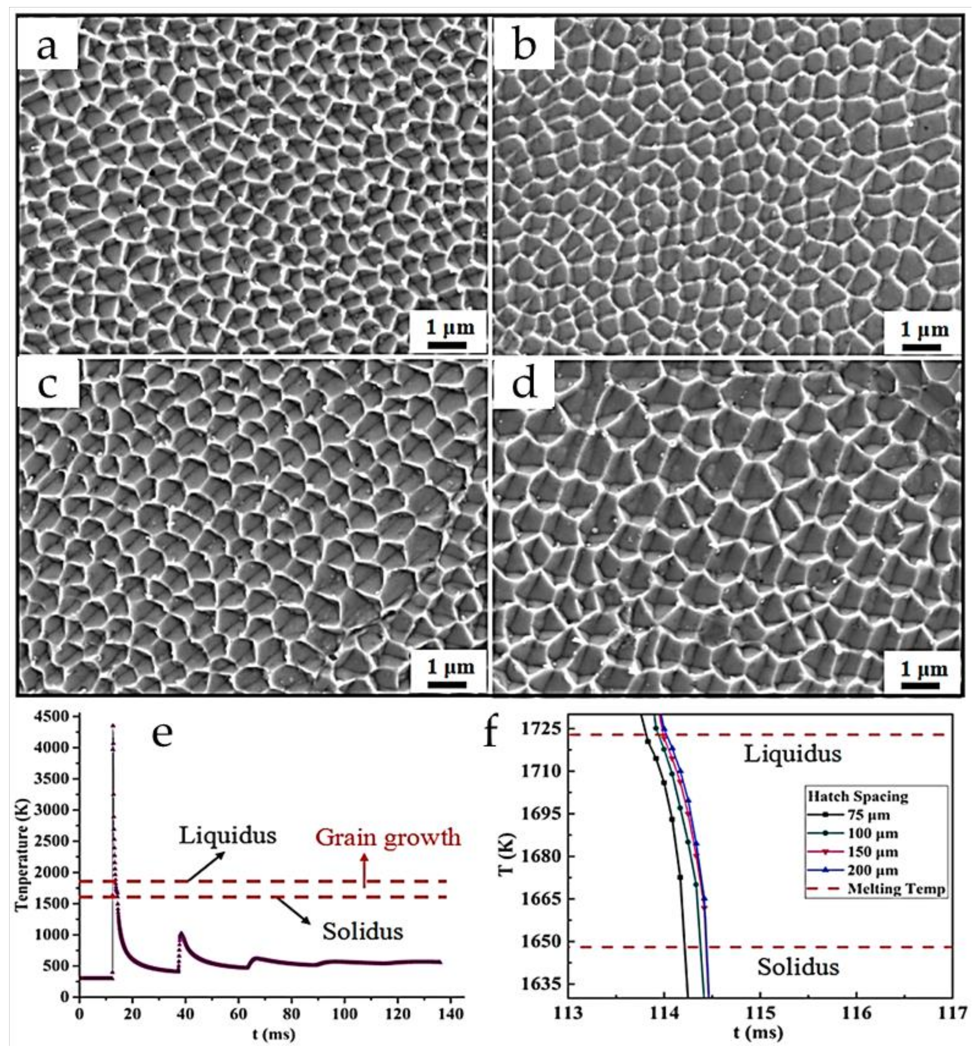
When understanding the influence of the melt pool, one of the first influencing factors is the melt pool size. The melt pool size is a generalized term representing physical quantities such as depth, width, and length. Melt pool width, for example, works very closely with hatch distance and can predict void-type defects between two adjacent tracks [80]. For example, if the melt pool width is large enough to overlap the other proceeding melt pools, the grain structure from the re-melted zone will differ. This was reported in the work of Dong et al. [81], where the hatch spacings correlated with the melt pool varied between 75 μm, 100 μm, 150 μm, and 200 μm. The underlying factor found was that the re-melted regions (from the melt pool overlap) experienced epitaxial growth, whereas fine equiaxed grains are present in the melt pool center. The growth rate describes these variations, and the temperature gradient of the grains, which is quantified by the cooling rate relation (for 316L SS), is described as follows:
λ = 80 T ˙ 0.33
where λ represents the microstructural size and T ˙ represents the cooling rate. According to this empirical equation, the high cooling rates enable refined cellular dendrite structures, which can be seen in Figure 4a–d. For further understanding, a finite elemental model (FEM) was formed to explicate the transition of the liquidus and solidus states of the 316L powder during laser melting (Figure 4e,f), which was related to the microstructural formation found in this work.
Understanding this point, the cooling rate has a large influence on the formation of the final microstructural formation of SLM steel components. Generally, the solidification rate and the cooling rate tend to be inversely proportional to each other as a function of laser power. This was observed in the work of Chen et al. [82], in which the solidification process of SLM H13 steel largely dictated the metallurgical characteristics of the alloy steel. In the case of cooling rates between 1.35 × 10⁶ °C/s and 1.89 × 10⁶ °C/s (which were suggested to be high), a non-equilibrium microstructure was formed. In this case, columnar-like structures combined with submicron-scale cellular grains were formed along the surface. This observation was attributed to the cooling rate time being so high that secondary dendrite arms were unable to fully form, thus resulting in the mixed microstructure. When the cooling rate was in the range of 5.6 × 10⁵ °C/s and 3.4 × 10⁶ °C/s, a gradient-dependent microstructure was formed, with cellular grains gradually transitioning to columnar dendrites of large size. As such, the primary takeaway is similar to the aforementioned discussion in the sense that when the cooling rate is increased, the microstructural formation can be refined.
From a laser scanning parameter perspective, the work of Liverani et al. [38] studies the influence of building direction (between 45° and 90 °C) on SLM’ed 316L SS. Upon observation of their cross-section, it was found that the grain cell size varied within the melt pools with their columnar growth towards the melting direction. The cells took an equiaxed-polygonal shape with a similar cellular size of 2 μm. Spherical nanoparticles were homogeneously distributed within and along the boundaries of the formed cells. It was speculated that Cr-based silicates were present due to the reaction between Cr and Si during the melting operation. To add, Riemer et al. [83] also found that for 316L SS, the elongation of the grains (along the heating direction) was largely directed to the <001> direction. However, the uni-directional grain structure was recrystallized through a HIP treatment into newly equiaxed grains. Wang et al. [84] also found that 316L SS tends to orient towards a {110} <001> arrangement. Their work also found that epitaxial growth (taking the form of a ±45° zigzag growth pattern) took place, with each cellular subgrain containing a relatively high density of dislocations. The formation of these cellular-like grains was due to the high cooling rates of the laser process, as they reached the order of 104–106 K/s [85]. As an alternative to Equation (2), the cooling rates of the laser process can allow for grain length quantification through the following equation [86]:
L = 1.7 × 10 11 T ˙ 3 6.2 × 10 8 T ˙ 2 + 8.2 × 10 5 T ˙ 117.5
L is the grain length (μm) and T ˙ is the cooling rate (K/s). In this rapid process, the distribution of elements on a nanoscale also largely affects the grain boundary formation, as their precipitate formation allows for the nano-oxide nucleation along the grain boundaries.
For complex 3D builds, Huang et al. [87] explored the effects of laser processing parameters on the microstructure of the 316L SS. In their work, a helical micro-diameter spring was fabricated by SLM using an island-fabricating approach at 90 J/mm3. Through varying the form angle (θ, at 0°, 30°, 60°), all samples were shown to have columnar grain growth with the melt pools taking an elliptical-like shape. Similar to the aforementioned studies, this finding was largely due to the heat-mass transfer effect from the temperature gradient along the surface. From a broader perspective, this work demonstrates that the microstructural formation mechanism remains the same regardless of the form angle.

4. Mechanical Properties

Understanding the structural and mechanical mechanisms of SLM steel, and their relatively dense and intergranular cellular formation (coupled with nano inclusions) allows for superior mechanical strength from a general perspective [76]. Of course, considering that SLM is a process that can produce anisotropic-like properties, the mechanical strength of SLM steel components can vary. This was shown in the work of Tolosa et al. [88], where traditional wrought AISI 316 SS was compared against its SLM’ed counterpart. Having been optimized to have an approximate 99.9%-part density, it was determined that the SLM steel yielded a superior yield strength (with the highest recorded value at 678 MPa) compared to the wrought steel (being recorded at 220–270 MPa). The tensile strength was also greater, with the highest value recorded at 691 MPa compared to the wrought steel value at 540–680 MPa. Although it was not elucidated on the mechanisms that allowed for this improvement, it can be speculated that the high cooling rates allowed for the formation finer grains than the wrought sample. Bartolomeu et al. [89] also came to the same conclusion with their experimental comparisons between the mechanical hardness and mechanical strength of SLM’ed 316L SS compared to its conventionally cast and hot-pressed 316L SS.
One point that was made, however, was that the direction of tensile testing varied the mechanical readings of the fabricated components, thus supporting the notion of anisotropy from SLM components. SLM components tend to be strongest along the build direction [90], assuming they are built in a bilateral scanning approach. Typically, the needle-like grain growth from the epitaxial formation largely governs the anisotropic performance of steel, as their interlockings enable a superior performance when loading (Figure 5a). For better visualization, the tensile strength and elongation at fracture for 17-4PH/316L SS at different polar angles (i.e., testing inclination concerning the layers) are shown in Figure 5b [91].
Yakout et al. [92] further understood these mechanisms and created a relationship between the LED and the mechanical strength of 316L SS (Figure 6a). According to their findings, the 316L SS components experienced a brittle fracturing from LED values below 62.5 J/mm3, as shown in Figure 6b. This was largely due to the incomplete melted zones and internal voids along the surface. However, at 62.5 J/mm3, a brittle-ductile transition occurred, signifying that the particles began to fuse sufficiently with fewer defects and voids (Figure 6c). Above this threshold value, the parts began to experience ductile failure. However, their tensile strength, yield strength, and resilience decreased as the LED increased, as shown in Figure 6d. It would be expected that with greater densification, the mechanical strength would increase. However, it was explicated that above this threshold value (and especially above an LED of 104.2 J/mm3, vaporization and an increasing presence of elemental microsegregation occurs. As chromium, manganese, and nickel have relatively low boiling points compared to elements such as iron, silicon, and molybdenum, they were vaporized throughout the melting process. Understanding this, a regression equation of the ultimate tensile mechanical strength ( u T ) of 316L SS was fabricated based on the relation of the LED component ( E v ) and the brittle-ductile LED transition point ( E T ). The equation is as follows:
W h e n   E v E T
u T = 1787 + 65.7 E v 0.4752 E v 2
W h e n   E v E T
u T = 488 + 26.15 E v 0.2280 E v 2 + 0.000621 E v 3
When formulating these equations, the underlying principle was based on the idea of interparticle bonding quality induced by the LED. Specifically, the melt pool at the optimized LED would allow for a dense, defect-free region, which would enhance the build’s mechanical strength. As such, the failure mechanism would consequentially change compared to a build with greater defects. Specifically, the failure mechanism would change from a ductile failure to a brittle failure. From this principle, the aforementioned equation was made possible.
Outside of yield strength, the LED heavily influences other mechanical properties, such as hardness. To further understand this relationship, the relationship of hardness to the LED of SLM (from various studies) is depicted in Figure 7 [89,93,94,95]. According to these findings, hardness gradually increases from 27 J/mm3 to 125 J/mm3, with the peak hardness recorded at 225 HV. This is largely due to the SLM process’s porosity and rapid cooling rates. However, beyond 125 J/mm3, the hardness then begins to decrease. This is due to the combination of vaporization of the melt pool along the surface and the coarsening of the cellular structures at the higher LED. This creates a lower capacity for the loaded region to withstand local deformation. However, from a broader perspective, one point worth investigating is the slight variation of hardness at lower LED from Saxena et al. [94] relative to the other reported works. To understand, factors varying from the powder fabrication technique to the average final particle size (as well as its distribution and elemental composition) can affect the structural and metallurgical characteristics of SLM steel, thus influencing their hardness properties. From another perspective, the influence of scanning patterns as well as the idea of elemental segregation due to the heating and resolidification process can also affect the hardness readings. It should also be mentioned that the loading conditions of the indenter, the location of indentation (whether it is on a porous region or a region that has weak particle bonding), and the geometrical feature of the indenter can also result in hardness reading deviations. Based on these factors, it can be speculated that one or some combination of these factors resulted in a higher hardness reading at lower LEDs. However, additional work is needed to fully understand these relationships. For a further understanding of the relationship between SLM steel and its mechanical properties, a summarization of the current literature is shown in Table 2.

5. Tribological Performance

Just as the mechanical performance of steels can be influenced by SLM, their tribological performance can also be impacted. Sun et al. [99] are among many who have studied these behaviors. In their work, they conducted a sliding wear test on SLM’ed 316L SS using pin-on-disk configurations and compared it with a standard bulk SS316L. Interestingly enough, in contrast to earlier findings that depict that SLM‘ed 316L SS has a higher hardness than wrought 316L SS, it was found that the wear volume of the SLM’ed steel was much greater than the wrought sample. It was reported that the wear rate was 6–17 times higher (depending on the scanning speed condition). However, upon closer inspection, this was largely due to the formed porosity within the substrate. By utilizing LED values of ~166 J/mm3, ~190 J/mm3, ~222 J/mm3, and ~266 J/mm3, high porosity volumes (as high as ~6.5%) were observed. About the wear mechanism, fracturing was primarily observed along the wear track, as the existing pores acted as crack initiation and propagation sights. As such, particle delamination occurred during tribo-testing, thus creating a greater cumulative wear loss.
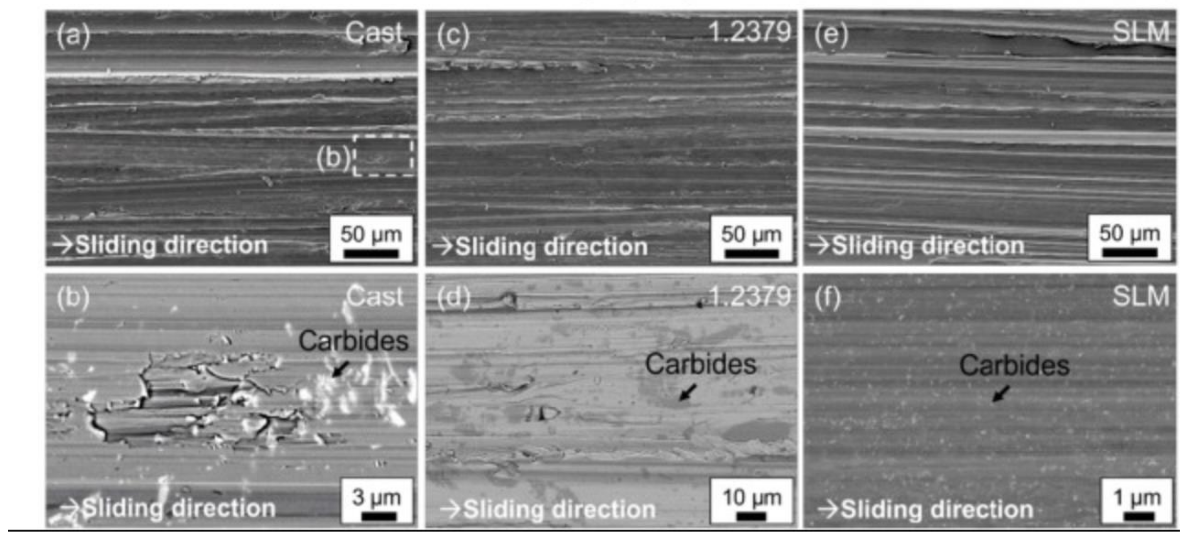
Sander et al. [100] performed wear studies on FeCrMoVC steel manufactured using SLM and casting techniques and compared it to 1.2379 (X155CrVMo12-1) steel. The authors adopted a pin-on-disk setup with a maximum force of 20 N, and the counter material was ceramic SiC P120. The authors observed high wear resistance in the SLM’ed component compared to the cast component and revealed that micro-cutting and micro-plowing were the wear mechanisms. The authors also summarized that these materials’ size, shape, and distribution of carbides could affect friction and wear studies. The scanning electron microscopic images captured using the secondary electron imaging mode of the wear surface on the three sheets of steel are shown in Figure 8. In SLM’ed and the cast component, the authors observed M2C and MC carbide types. However, in the SLM’ed component, these carbides are refined and distributed evenly. In addition, they also have a higher volume fraction, which enables the SLM substrate to have a greater wear resistance compared to the cast steel. In cast steel, carbide breakouts in larger areas were observed, which led to reduced wear resistance. The reference steel also contains carbides of Cr7C3, which are soft compared to M2C and MC, and during tribological testing, these carbides are cut by the hard particle, and no breakout is observed. The reference steel thus possesses higher wear resistance compared to the cast steel.
Zhu et al. Field [76] conducted wear studies on the SLM’ed SS 316L and traditional processing routes from a lubrication standpoint. The authors performed tribological testing in ring-on-disc rig equipment under lubricated conditions (with L-HM 46 anti-wear hydraulic oil) with a maximum load of 10 N. In this experiment, the authors observed reduced friction on SLM’ed SS316L compared to traditionally manufactured SS 316L. The authors largely attributed these findings to the refined microstructure present in the SLM substrates. Although some pores were along the surface, the hardness was the main contributor to the reduced wear rate.
Understanding that the microstructure and porosity can largely influence the wear rate of SLM’ed steel, many have sought to add nanocomposites to strengthen their tribological performance. This was observed in Wen et al. [101], where it was revealed that the wear resistance of SLM’ed S136 mould steel was enhanced when different wt. % (0, 0.5, 1, and 1.5) nano TiB2 particles were added. The wear performance is identified by conducting dry sliding wear tests with a Si3N4 ceramic ball with a load of 50 N. The sliding speed of 600 rpm and holding time of 30 min were chosen for these experiments. The authors reported that the mold steel fabricated using 0.5 wt.% TiB2 showed a reduced coefficient of friction (COF) and wear. For reference, Figure 9 shows the worn surface of the pure mold steel and mold steel manufactured using SLM with different wt.% of TiB2.
Based on the findings of Figure 9, the worn surfaces of pure mold steel show irregularly shaped fragments, representing abrasive wear. For the SLM component containing 0.5 wt.% TiB2, the surface exhibited shallow grooves with a strain-hardened tribo-layer, thus indicating adhesive wear. When the TiB2 content was increased, delamination and spalling were observed along the wear track. Nonetheless, it was concluded that the TiB2 reinforcement allowed for the formation of nanoscale structures, which allowed for grain boundary strengthening and grain refinement.
Under post-processing conditions, Shin et al. [102] divulged the influence of heat treatment on SLM’ed SS316L and studied the influence on its wear behavior. The SLM’ed components were subjected to the following two different heat treatments: a furnace type and a hot isostatic pressing treatment. These samples were then compared to cold-rolled (CR) steel. A dry sliding wear test was performed using a pin-on-disk configuration, and grey cast iron was used as the counter body. The sliding speed used in these experiments was 28.8 mm/s, and the normal load was 30 N. Three different types of SLM’ed SS 316 were considered in this study. A non-heat treated (as-SLM), furnace heat treated (HT-SLM), and hot isostatic pressed (HIP-SLM). The wear studies were performed on these three-heat-treated SLM specimens and compared with a cold-rolled SS316L. The samples are further classified based on laser power and scan rate. In each case, two samples were considered with a laser power of 120 W with a scanning speed of 100 mm/s and 280 mm/s. The COF, wear loss, and worn surface characterization from this work is shown in Figure 10.
According to their findings, the authors report a low COF for cold-rolled SS 316L, whereas a high COF was observed for HT-SLM and HIP-SLM, as shown in Figure 10a,b. The authors revealed a stable COF for the CR steel compared to the SLM’ed steels. The COF values in CR steels were within the range from 0.47 to 0.52. However, the SLM’ed SS316L exhibited a stick-slip behavior as the COF largely fluctuated. In fact, under the influence of HT, the SLM substrate experienced an increase in friction due to the low surface hardness induced by the heat treatment. The stick-slip behavior led to an increase in COF. The breaking of adhesion in the contact area increased. In addition, the porous structure in SLM specimens leads to the accumulation of more wear debris in the pores (Figure 10d–f). Under high pressure, the wear debris cold welded to the pores and wear tracks, leading to a rough contact; hence a large COF was observed (which was further supported by an EDS analysis, as shown in Figure 10g). Collectively, although post-treatment influence can densify the surfaces, it comes at the expense of hardness reduction, thus resulting in a greater cumulative wear loss, as shown in Figure 10c. For a further understanding of the relationship between SLM steel and its tribological properties requires a summarization of the current literature, which is shown in Table 3.

6. Corrosion Performance

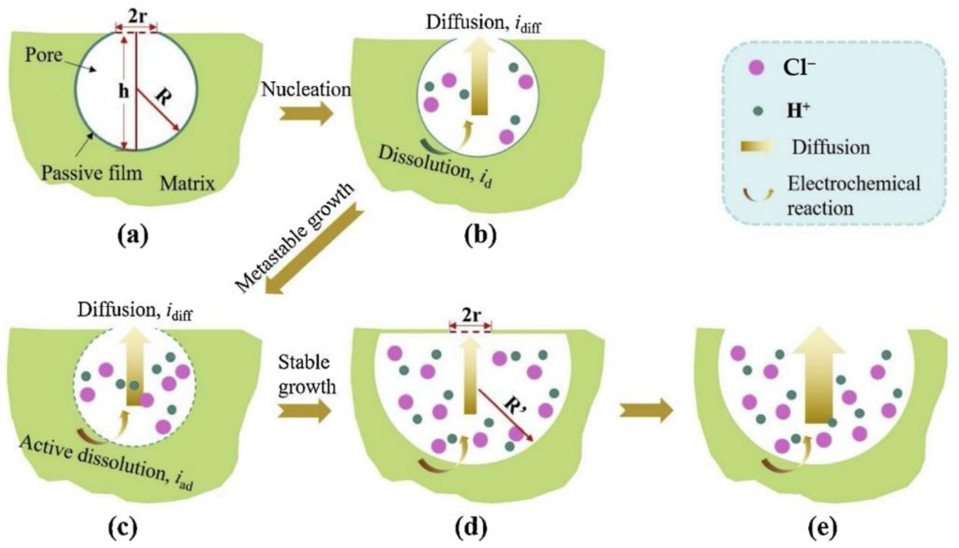
In addition to the tribological performance of SLM steels, their performance in electrochemical environments has been widely investigated. According to Cruz et al. [103], the influence of compressive residual stresses in SLM’ed steels (under optimized conditions) can improve the formation of the passive film and assist with pitting resistance. This can largely be due to the lack of point defect concentrations (i.e., oxygen vacancies), which prevent the adsorption and penetration of Cl ions. As such, the kinetics of the passive film formation (through oxide film growth) allows for sufficient protection against surface pitting. However, Sander et al. [104] suggest that the influence of residual stresses does not have nearly as big an impact as the alloy chemistry of SLM steels when concerning their corrosion protection. In a separate work by Sander et al. [105], they reported that the degree of stable metal pitting increases as the porous content increases due to the intrinsic porosity defect of SLM. The pitting mechanisms for SLM SS are largely tied to the gas pores induced by the laser melting process. Duan et al. [106] elucidate this concept by explicating metastable pitting growth to stable pitting growth in SLM’ed steels, which can be conceptualized in Figure 11.
According to their work, the electrochemical reactions along the pit consist of a hydrolysis-based reaction (of H+ and Cl), in which the Cl moves into the pit to allow for a localized balanced charge to ensure electroneutrality. In the first stage, a thin passive film is formed along the pore surface due to the formation of metal cations, which can be seen in Figure 11a. However, as shown in Figure 11b, the film dissolution rate increases as the potential begins to vary. This film dissolution rate also depends on the film dissolution rate on the gas pore surface, resulting in metastable pitting, which can be seen in Figure 11c. Eventually, due to the decrease in pH values (within the porous region) and the accumulation of metal cations, active state dissolution of the metal occurs, thus resulting in stable growth, assuming that repassivation does not occur (Figure 11d). If this trend continues, exacerbated pitting will occur (Figure 11e). Compared to wrought SS, the difference largely pertains to the locations at which the metastable pitting occurs. For wrought SS, pitting always occurs at the MnS inclusions, which occurs much more frequently than SLM’ed SS. This is largely due to the stability of the passive film, which can be attributed to the finer microstructure formed by the rapid-cooling process of SLM.
Understanding that SLM’ed steel does not suffer from the defect of MnS inclusions, Chao et al. [107] were able to elucidate why these inclusions don’t exist and provide additional information on the corrosion performance of SLM’ed 316L SS. When considering traditional SS, MnS inclusions are associated with the depletion of Cr, an element that helps with oxide film formation. Their presence is due to the steel-making process, as various nitrides (e.g., MnO and SiO2) float to the surface of steel due to their thermodynamic stability. This formed slag can precipitate during the solidification process, in which the most common product of its solubility is MnS. In contrast to this, the rapid solidification of the melted powder does not give sufficient time for the Mn and S to diffuse into the oxide particles (of the molten metal), thus eliminating these inclusions. Instead, the element (i.e., the Cr composition in the matrix) is heterogeneously distributed, allowing greater oxide film formation and protection.
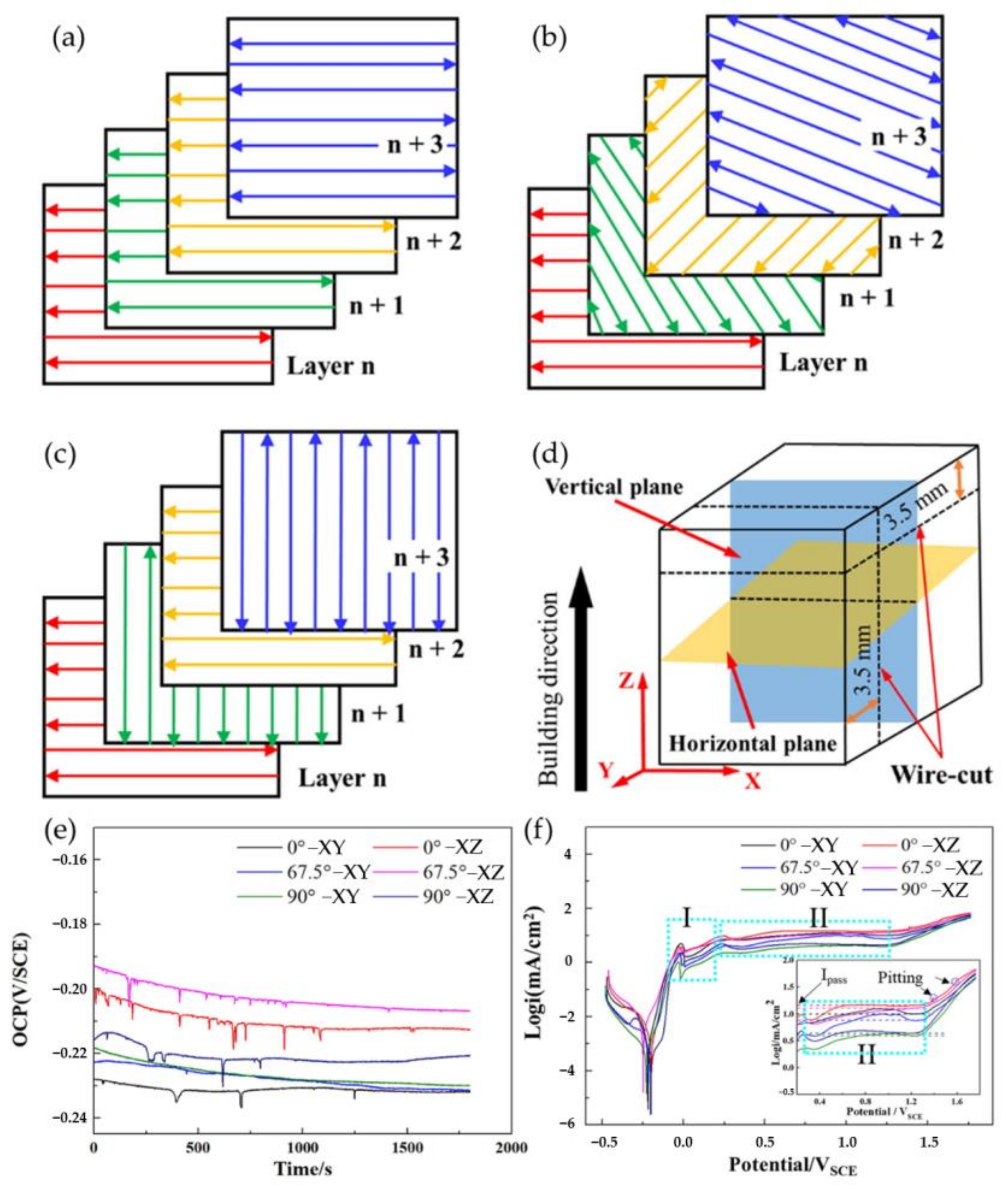
With the mechanisms behind the pitting formation of steels now understood, it is important to see how SLM process parameters also influence their general corrosion resistance. Zhao et al. [108] found that scanning strategies influence their corrosion performance due to the anisotropic formation of the microstructure. In their work, the scanning strategies varied between 0°, 67.5°, and 90° rotations. Their corrosion characteristics were then evaluated along the XY and XZ planes, perpendicular and parallel to the scanning path. Electrochemical experiments found that the corrosion resistance of the specimens along the XY planes was superior to those of the XZ planes. This can largely be due to the intrinsic anisotropic properties of SLM, as the laser melting tends to create columnar grains along the melting direction. For reference, these findings can be seen in Figure 12.
Additionally, it was found that the 90° rotation yielded superior corrosion resistance, followed by the 0° and 67.5° rotations. This was due to the complex crystallographic formation as the temperature gradient allowed for the formation of square-like grains. Their native oxide film formation before electrochemical treatment was greater, thus allowing for improved corrosion resistance. Interestingly enough, across all specimens, the pitting corrosion rate was largely found along the melt track boundaries of all specimens. This observation was attributed to the formation of defects such as pores, elemental segregation, inhomogeneous microstructure, thermal stresses, and high interfacial free energy.
With the corrosion resistance of SLM steel outperforming traditionally cast steel, many have sought to improve their corrosion behavior through post-processing methods. Kong et al. [109] investigated this concept by applying post-heat treatment to SLM’ed 316L SS to mitigate the porous defects associated with SLM. Varying the heat treatment between 1050 °C and 1200 °C, the SLM specimens were subsequentially water-cooled to ensure homogeneity within the microstructure. Interestingly enough, the porosity increased when subjected to heat treatment. Although the authors did not elucidate why this happened, this is likely due to the gas pressure within the pores and the inhibition of diffusion movement within the voids [110]. Similarly, the heat treatment also decreased the dislocation density and reduced the compressive residual stresses of the laser treatment, which in turn also decreased the pitting potential of the substrates. It is suggested that other treatments, such as hot isostatic pressing, be utilized to decrease the porous content of the SLM builds. Additionally, using techniques such as friction stir processing (FSP), ultrasonic surface rolling (USR), and ultrasonic nanocrystal surface modification (UNSM) can also improve their microstructural features, which can further improve their corrosion resistance [111,112,113]. To further understand the relationship between SLM steel and its corrosion resistance, a summarization of the current literature is shown in Table 4.

7. Summary and Future Outlook

With the immense technological advancements of Industry 4.0, AM has attracted the attention of many due to its ability to rapidly fabricate robust and reliable components. Among many of the existing AM technologies, SLM has been one of the most widely investigated AM techniques due to its ability to effectively tailor the mechanical, tribological, and corrosion properties of various materials. In essence, SLM is a laser powder bed fusion process widely utilized to manufacture layer-by-layer metallic parts and coatings. By utilizing the thermal energy of a high-powered laser, metallic powders along a powder bed are effectively melted in a contained inert gas atmosphere (typically composed of nitrogen, helium, and/or argon) and solidified to form a 3D component. The flexibility of manufacturing parts with a wide variety of dimensions and geometries while controlling the microstructural components of the build creates an interesting processing route for a wide range of alloys. However, many studies focus on softer materials such as Al or Mg due to their thermal expansion properties rather than steel. Understanding that steel components are widely used in critical industries such as automotive, structural, and aerospace, there is an increasing need to understand the formation mechanisms of SLM steel and their performance in mechanical, tribological, and corrosive environments. This review encapsulates the most current literature on SLM of steel and elucidates these components’ various formation and performance mechanisms. It was found that the influence of LED and scanning strategy affects the structural formation of SLM’ed steels. LED values between 100 J/mm3 and 200 J/mm3 allow for relatively dense and porous-free (>1%) components, with the highest density being recorded at ~99.6% (at an LED of 159 J/mm3). Similarly, minimizing the thermal gradients along the build minimizes distortion and cracking defects, which are largely dependent on the cooling rates. As the cooling rates are dependent on the scanning strategy and LED, cooling rates between 1.35 × 10⁶ °C/s and 1.89 × 10⁶ °C/s were found to form refined submicron-scale cellular grains within SLM steel builds. When processing parameters are optimized, equiaxed grains can be achieved, improving these components’ mechanical, tribological, and corrosion performance. With these mechanisms now known, it is suggested that research now be directed to the study of SLM with composites and steel components. By doing so, their performance can be further improved, thus enhancing the knowledge in this research field and creating a benefit for its industrial application.

Author Contributions

Conceptualization, A.M.R., M.J. and P.L.M.; methodology, A.M.R., M.J., J.N., J.L., K.L., I.N., N.H. and P.L.M.; software, A.M.R., J.N., J.L., K.L., I.N. and N.H.; validation, A.M.R., M.J. and P.L.M.; formal analysis, A.M.R., M.J. and P.L.M.; investigation, A.M.R., M.J. and P.L.M.; resources, A.M.R., M.J., J.N., J.L., K.L., I.N., N.H. and P.L.M.; data curation, A.M.R., M.J., J.N., J.L., K.L., I.N. and N.H.; writing—original draft preparation, A.M.R., M.J., J.N., J.L., K.L., I.N., N.H. and P.L.M.; writing—review and editing, A.M.R., M.J. and P.L.M.; visualization, A.M.R., M.J. and P.L.M.; supervision, P.L.M.; project administration, A.M.R. and P.L.M.; All authors have read and agreed to the published version of the manuscript.

Funding

This research received no external funding.

Data Availability Statement

Data sharing is not applicable to this article.

Conflicts of Interest

The authors declare no conflict of interest.

References

  1. Dilberoglu, U.M.; Gharehpapagh, B.; Yaman, U.; Dolen, M. The Role of Additive Manufacturing in the Era of Industry 4.0. Procedia Manuf. 2017, 11, 545–554. [Google Scholar] [CrossRef]
  2. Watson, J.; Taminger, K. A decision-support model for selecting additive manufacturing versus subtractive manufacturing based on energy consumption. J. Clean. Prod. 2018, 176, 1316–1322. [Google Scholar] [CrossRef] [PubMed]
  3. Thomas, D.S.; Gilbert, S.W. Costs and Cost Effectiveness of Additive Manufacturing; National Institute of Standards and Technology: Gaithersburg, MD, USA, 2014; NIST SP 1176. [Google Scholar] [CrossRef]
  4. Sun, C.; Wang, Y.; McMurtrey, M.D.; Jerred, N.D.; Liou, F.; Li, J. Additive manufacturing for energy: A review. Appl. Energy 2020, 282, 116041. [Google Scholar] [CrossRef]
  5. Bhole, K.S.; Kale, B. Techniques to minimise stair-stepping effect in micro-stereolithography process: A Review. Adv. Mater. Process. Technol. 2021, 1–20. [Google Scholar] [CrossRef]
  6. Ralls, A.M.; Kumar, P.; Menezes, P.L. Tribological Properties of Additive Manufactured Materials for Energy Applications: A Review. Processes 2020, 9, 31. [Google Scholar] [CrossRef]
  7. Gokuldoss, P.K.; Kolla, S.; Eckert, J. Additive Manufacturing Processes: Selective Laser Melting, Electron Beam Melting and Binder Jetting—Selection Guidelines. Materials 2017, 10, 672. [Google Scholar] [CrossRef] [Green Version]
  8. Munir, K.; Biesiekierski, A.; Wen, C.; Li, Y. 7—Selective laser melting in biomedical manufacturing. In Metallic Biomaterials Processing and Medical Device Manufacturing; Wen, C., Ed.; Woodhead Publishing: Sawston, UK, 2020; pp. 235–269. [Google Scholar] [CrossRef]
  9. Chen, H.; Zhang, C.; Jia, D.; Wellmann, D.; Liu, W. Corrosion Behaviors of Selective Laser Melted Aluminum Alloys: A Review. Metals 2020, 10, 102. [Google Scholar] [CrossRef] [Green Version]
  10. Zhu, Y.; Zou, J.; Yang, H.-Y. Wear performance of metal parts fabricated by selective laser melting: A literature review. J. Zhejiang Univ. A 2018, 19, 95–110. [Google Scholar] [CrossRef]
  11. Wirth, F.; Frauchiger, A.; Gutknecht, K.; Cloots, M. Influence of the Inert Gas Flow on the Laser Powder Bed Fusion (LPBF) Process. In Industrializing Additive Manufacturing; Springer: Cham, Switzerland, 2021; pp. 192–204. [Google Scholar] [CrossRef]
  12. Amano, H.; Ishimoto, T.; Suganuma, R.; Aiba, K.; Sun, S.-H.; Ozasa, R.; Nakano, T. Effect of a helium gas atmosphere on the mechanical properties of Ti-6Al-4V alloy built with laser powder bed fusion: A comparative study with argon gas. Addit. Manuf. 2021, 48, 102444. [Google Scholar] [CrossRef]
  13. Pauzon, C.; Forêt, P.; Hryha, E.; Arunprasad, T.; Nyborg, L. Argon-helium mixtures as Laser-Powder Bed Fusion atmospheres: Towards increased build rate of Ti-6Al-4V. J. Mater. Process. Technol. 2019, 279, 116555. [Google Scholar] [CrossRef]
  14. Braun, J.; Kaserer, L.; Stajkovic, J.; Leitz, K.-H.; Tabernig, B.; Singer, P.; Leibenguth, P.; Gspan, C.; Kestler, H.; Leichtfried, G. Molybdenum and tungsten manufactured by selective laser melting: Analysis of defect structure and solidification mechanisms. Int. J. Refract. Met. Hard Mater. 2019, 84, 10499. [Google Scholar] [CrossRef]
  15. Yap, C.Y.; Chua, C.K.; Dong, Z.L.; Liu, Z.H.; Zhang, D.Q.; Loh, L.E.; Sing, S.L. Review of selective laser melting: Materials and applications. Appl. Phys. Rev. 2015, 2, 41101. [Google Scholar] [CrossRef]
  16. Emerald Group Publishing Limited. A Focus on SLM and SLS Methods in 3D Printing; Emerald Group Publishing Limited: Bingley, UK, 2015. Available online: https://unr.idm.oclc.org/login?url=https://search.ebscohost.com/login.aspx?direct=true&db=e025xna&AN=1423628&site=ehost-live&scope=site (accessed on 12 November 2021).
  17. Thomas, D.S. Economics of the U.S. Additive Manufacturing Industry; National Institute of Standards and Technology: Gaithersburg, MD, USA, 2013; NIST SP 1163. [Google Scholar] [CrossRef]
  18. Tofail, S.A.; Koumoulos, E.P.; Bandyopadhyay, A.; Bose, S.; O’Donoghue, L.; Charitidis, C. Additive manufacturing: Scientific and technological challenges, market uptake and opportunities. Mater. Today 2018, 21, 22–37. [Google Scholar] [CrossRef]
  19. Bose, S.; Ke, D.; Sahasrabudhe, H.; Bandyopadhyay, A. Additive manufacturing of biomaterials. Prog. Mater. Sci. 2017, 93, 45–111. [Google Scholar] [CrossRef]
  20. Bikas, H.; Stavropoulos, P.; Chryssolouris, G. Additive manufacturing methods and modelling approaches: A critical review. Int. J. Adv. Manuf. Technol. 2015, 83, 389–405. [Google Scholar] [CrossRef] [Green Version]
  21. Ralls, A.M.; Kasar, A.K.; Daroonparvar, M.; Siddaiah, A.; Kumar, P.; Kay, C.M.; Misra, M.; Menezes, P.L. Effect of Gas Propellant Temperature on the Microstructure, Friction, and Wear Resistance of High-Pressure Cold Sprayed Zr702 Coatings on Al6061 Alloy. Coatings 2022, 12, 263. [Google Scholar] [CrossRef]
  22. Ralls, A.M.; Daroonparvar, M.; Sikdar, S.; Rahman, H.; Monwar, M.; Watson, K.; Kay, C.M.; Menezes, P.L. Tribological and Corrosion Behavior of High Pressure Cold Sprayed Duplex 316 L Stainless Steel. Tribol. Int. 2022, 169, 107471. [Google Scholar] [CrossRef]
  23. Gibson, I.; Rosen, D.; Stucker, B. Additive Manufacturing Technologies; Springer: New York, NY, USA, 2015. [Google Scholar] [CrossRef]
  24. Frazier, W.E. Metal Additive Manufacturing: A Review. J. Mater. Eng. Perform. 2014, 23, 1917–1928. [Google Scholar] [CrossRef]
  25. Bandyopadhyay, A.; Traxel, K.D. Invited review article: Metal-additive manufacturing—Modeling strategies for application-optimized designs. Addit. Manuf. 2018, 22, 758–774. [Google Scholar] [CrossRef]
  26. Piekło, J.; Garbacz-Klempka, A. Use of Selective Laser Melting (SLM) as a Replacement for Pressure Die Casting Technology for the Production of Automotive Casting. Arch. Foundry Eng. 2020, 21, 9–16. [Google Scholar] [CrossRef]
  27. DebRoy, T.; Wei, H.L.; Zuback, J.S.; Mukherjee, T.; Elmer, J.W.; Milewski, J.O.; Beese, A.M.; Wilson-Heid, A.; De, A.; Zhang, W. Additive manufacturing of metallic components–Process, structure and properties. Prog. Mater. Sci. 2018, 92, 112–224. [Google Scholar] [CrossRef]
  28. Kokareva, V.V.; Smelov, V.G.; Agapovichev, A.V.; Sotov, A.V.; Sufiiarov, V.S. Development of SLM quality system for gas turbines engines parts production. IOP Conf. Ser. Mater. Sci. Eng. 2018, 441, 12024. [Google Scholar] [CrossRef]
  29. Wang, Y.; Tan, Q.; Pu, F.; Boone, D.; Zhang, M. A Review of the Application of Additive Manufacturing in Prosthetic and Orthotic Clinics from a Biomechanical Perspective. Engineering 2020, 6, 1258–1266. [Google Scholar] [CrossRef]
  30. Leal, R.; Barreiros, F.; Alves, M.; Romeiro, F.; Vasco, J.C.; Santos, M.; Marto, C. Additive manufacturing tooling for the automotive industry. Int. J. Adv. Manuf. Technol. 2017, 92, 1671–1676. [Google Scholar] [CrossRef]
  31. Armillotta, A.; Baraggi, R.; Fasoli, S. SLM tooling for die casting with conformal cooling channels. Int. J. Adv. Manuf. Technol. 2014, 71, 573–583. [Google Scholar] [CrossRef]
  32. Wong, M.; Tsopanos, S.; Sutcliffe, C.J.; Owen, I. Selective laser melting of heat transfer devices. Rapid Prototyp. J. 2007, 13, 291–297. [Google Scholar] [CrossRef]
  33. Romei, F.; Grubišić, A.N.; Gibbon, D. Manufacturing of a high-temperature resistojet heat exchanger by selective laser melting. Acta Astronaut. 2017, 138, 356–368. [Google Scholar] [CrossRef] [Green Version]
  34. Francois, M.; Sun, A.; King, W.; Henson, N.; Tourret, D.; Bronkhorst, C.; Carlson, N.; Newman, C.; Haut, T.; Bakosi, J.; et al. Modeling of additive manufacturing processes for metals: Challenges and opportunities. Curr. Opin. Solid State Mater. Sci. 2017, 21, 198–206. [Google Scholar] [CrossRef]
  35. Simmons, J.C.; Chen, X.; Azizi, A.; Daeumer, M.A.; Zavalij, P.Y.; Zhou, G.; Schiffres, S.N. Influence of processing and microstructure on the local and bulk thermal conductivity of selective laser melted 316L stainless steel. Addit. Manuf. 2019, 32, 100996. [Google Scholar] [CrossRef]
  36. Singh, D.D.; Mahender, T.; Reddy, A.R. Powder bed fusion process: A brief review. Mater. Today Proc. 2021, 46, 350–355. [Google Scholar] [CrossRef]
  37. Blakey-Milner, B.; Gradl, P.; Snedden, G.; Brooks, M.; Pitot, J.; Lopez, E.; Leary, M.; Berto, F.; du Plessis, A. Metal additive manufacturing in aerospace: A review. Mater. Des. 2021, 209, 110008. [Google Scholar] [CrossRef]
  38. Liverani, E.; Toschi, S.; Ceschini, L.; Fortunato, A. Effect of selective laser melting (SLM) process parameters on microstructure and mechanical properties of 316L austenitic stainless steel. J. Mater. Process. Technol. 2017, 249, 255–263. [Google Scholar] [CrossRef]
  39. Jafari, D.; Wits, W.W. The utilization of selective laser melting technology on heat transfer devices for thermal energy conversion applications: A review. Renew. Sustain. Energy Rev. 2018, 91, 420–442. [Google Scholar] [CrossRef]
  40. Attaran, M. The rise of 3-D printing: The advantages of additive manufacturing over traditional manufacturing. Bus. Horiz. 2017, 60, 677–688. [Google Scholar] [CrossRef]
  41. Fish, E. Rapid Prototyping: How It’s Done at GM. Automot. Des. Prod. 2011, 123, 46–48. [Google Scholar]
  42. Stolt, R.; André, S.; Elgh, F. Introducing Inserts for Die Casting Manufactured by Selective Laser Sintering. Procedia Manuf. 2018, 17, 309–316. [Google Scholar] [CrossRef]
  43. Thomas, D.S. Costs, benefits, and adoption of additive manufacturing: A supply chain perspective. Int. J. Adv. Manuf. Technol. 2015, 85, 1857–1876. [Google Scholar] [CrossRef] [Green Version]
  44. Wang, J.; Liu, S.; Fang, Y.; He, Z. A short review on selective laser melting of H13 steel. Int. J. Adv. Manuf. Technol. 2020, 108, 2453–2466. [Google Scholar] [CrossRef]
  45. Hällgren, S.; Pejryd, L.; Ekengren, J. Additive Manufacturing and High Speed Machining -cost Comparison of short Lead Time Manufacturing Methods. Procedia CIRP 2016, 50, 384–389. [Google Scholar] [CrossRef] [Green Version]
  46. JVasco, J.; Barreiros, F.; Nabais, A.; Reis, N. Additive manufacturing applied to injection moulding: Technical and economic impact. Rapid Prototyp. J. 2019, 25, 1241–1249. [Google Scholar] [CrossRef]
  47. Jing, G.; Huang, W.; Yang, H.; Wang, Z. Microstructural evolution and mechanical properties of 300M steel produced by low and high power selective laser melting. J. Mater. Sci. Technol. 2020, 48, 44–56. [Google Scholar] [CrossRef]
  48. ASM Ready Reference: Thermal Properties of Metals—ASM International. Available online: https://www.asminternational.org/home/-/journal_content/56/10192/06702G/PUBLICATION (accessed on 15 November 2021).
  49. Lowther, M.; Louth, S.; Davey, A.; Hussain, A.; Ginestra, P.; Carter, L.; Eisenstein, N.; Grover, L.; Cox, S. Clinical, industrial, and research perspectives on powder bed fusion additively manufactured metal implants. Addit. Manuf. 2019, 28, 565–584. [Google Scholar] [CrossRef] [Green Version]
  50. Alvi, S.; Saeidi, K.; Akhtar, F. High temperature tribology and wear of selective laser melted (SLM) 316L stainless steel. Wear 2020, 448, 203228. [Google Scholar] [CrossRef]
  51. Li, B.; Wang, T.; Li, P.; Wang, S.; Wang, L. Selective Laser Melting of 316L Stainless Steel: Influence of Co-Cr-Mo-W Addition on Corrosion Resistance. Metals 2021, 11, 597. [Google Scholar] [CrossRef]
  52. Ralls, A.; Kumar, P.; Misra, M.; Menezes, P.L. Material Design and Surface Engineering for Bio-implants. JOM 2020, 72, 684–696. [Google Scholar] [CrossRef]
  53. Kwon, O.; Lee, K.Y.; Kim, G.S.; Chin, K.G. New Trends in Advanced High Strength Steel Developments for Automotive Application. Mater. Sci. Forum 2010, 638–642, 136–141. [Google Scholar] [CrossRef]
  54. Hashemi, P.M.; Borhani, E.; Nourbakhsh, M.S. A review on nanostructured stainless steel implants for biomedical application. Nanomed. J. 2016, 3, 202–216. [Google Scholar]
  55. Pradeep, P.I.; Kumar, V.A.; Sriranganath, A.; Singh, S.K.; Sahu, A.; Kumar, T.S.; Narayanan, P.R.; Arumugam, M.; Mohan, M. Characterization and Qualification of LPBF Additively Manufactured AISI-316L Stainless Steel Brackets for Aerospace Application. Trans. Indian Natl. Acad. Eng. 2020, 5, 603–616. [Google Scholar] [CrossRef]
  56. Röttger, A.; Boes, J.; Theisen, W.; Thiele, M.; Esen, C.; Edelmann, A.; Hellmann, R. Microstructure and mechanical properties of 316L austenitic stainless steel processed by different SLM devices. Int. J. Adv. Manuf. Technol. 2020, 108, 769–783. [Google Scholar] [CrossRef]
  57. Liu, S.; Guo, H. Balling Behavior of Selective Laser Melting (SLM) Magnesium Alloy. Materials 2020, 13, 3632. [Google Scholar] [CrossRef]
  58. Li, R.; Liu, J.; Shi, Y.; Wang, L.; Jiang, W. Balling behavior of stainless steel and nickel powder during selective laser melting process. Int. J. Adv. Manuf. Technol. 2012, 59, 1025–1035. [Google Scholar] [CrossRef]
  59. Afkhami, S.; Dabiri, M.; Alavi, S.H.; Björk, T.; Salminen, A. Fatigue characteristics of steels manufactured by selective laser melting. Int. J. Fatigue 2019, 122, 72–83. [Google Scholar] [CrossRef]
  60. Mertens, R.; Dadbakhsh, S.; Van Humbeeck, J.; Kruth, J.-P. Application of base plate preheating during selective laser melting. Procedia CIRP 2018, 74, 5–11. [Google Scholar] [CrossRef]
  61. Stern, F.; Kleinhorst, J.; Tenkamp, J.; Walther, F. Investigation of the anisotropic cyclic damage behavior of selective laser melted AISI 316L stainless steel. Fatigue Fract. Eng. Mater. Struct. 2019, 42, 2422–2430. [Google Scholar] [CrossRef]
  62. Gao, S.; Hu, Z.; Duchamp, M.; Krishnan, P.S.S.R.; Tekumalla, S.; Song, X.; Seita, M. Recrystallization-based grain boundary engineering of 316L stainless steel produced via selective laser melting. Acta Mater. 2020, 200, 366–377. [Google Scholar] [CrossRef]
  63. Alnajjar, M.; Christien, F.; Wolski, K.; Bosch, C. Evidence of austenite by-passing in a stainless steel obtained from laser melting additive manufacturing. Addit. Manuf. 2018, 25, 187–195. [Google Scholar] [CrossRef]
  64. Alnajjar, M.; Christien, F.; Bosch, C.; Wolski, K. A comparative study of microstructure and hydrogen embrittlement of selective laser melted and wrought 17–4 PH stainless steel. Mater. Sci. Eng. A 2020, 785, 139363. [Google Scholar] [CrossRef]
  65. Gu, D.; Shen, Y. Balling phenomena in direct laser sintering of stainless steel powder: Metallurgical mechanisms and control methods. Mater. Des. 2009, 30, 2903–2910. [Google Scholar] [CrossRef]
  66. Khairallah, S.A.; Anderson, A. Mesoscopic simulation model of selective laser melting of stainless steel powder. J. Mater. Process. Technol. 2014, 214, 2627–2636. [Google Scholar] [CrossRef]
  67. Chen, H.; Gu, D.; Dai, D.; Ma, C.; Xia, M. Microstructure and composition homogeneity, tensile property, and underlying thermal physical mechanism of selective laser melting tool steel parts. Mater. Sci. Eng. A 2017, 682, 279–289. [Google Scholar] [CrossRef]
  68. Spierings, A.B.; Levy, G. Comparison of Density of Stainless Steel 316L Parts Produced with Selective Laser Melting using Different Powder Grades. In Proceedings of the 2009 International Solid Freeform Fabrication Symposium, Austin, TX, USA, 3–5 August 2009. [Google Scholar] [CrossRef]
  69. Abd-Elghany, K.; Bourell, D. Property evaluation of 304L stainless steel fabricated by selective laser melting. Rapid Prototyp. J. 2012, 18, 420–428. [Google Scholar] [CrossRef]
  70. Zhang, J.; Song, B.; Wei, Q.; Bourell, D.; Shi, Y. A review of selective laser melting of aluminum alloys: Processing, microstructure, property and developing trends. J. Mater. Sci. Technol. 2019, 35, 270–284. [Google Scholar] [CrossRef]
  71. Huang, W.; Zhang, W.; Chen, X. Effect of SLM Process Parameters on Relative Density of Maraging Steel (18Ni-300) Formed Parts. IOP Conf. Ser. Mater. Sci. Eng. 2020, 774, 012027. [Google Scholar] [CrossRef]
  72. Qiu, C.; Al Kindi, M.; Aladawi, A.S.; Al Hatmi, I. A comprehensive study on microstructure and tensile behaviour of a selectively laser melted stainless steel. Sci. Rep. 2018, 8, 7785. [Google Scholar] [CrossRef] [Green Version]
  73. Nong, X.; Zhou, X. Effect of scanning strategy on the microstructure, texture, and mechanical properties of 15-5PH stainless steel processed by selective laser melting. Mater. Charact. 2021, 174, 111012. [Google Scholar] [CrossRef]
  74. Song, Y.; Sun, Q.; Guo, K.; Wang, X.; Liu, J.; Sun, J. Effect of scanning strategies on the microstructure and mechanical behavior of 316L stainless steel fabricated by selective laser melting. Mater. Sci. Eng. A 2020, 793, 139879. [Google Scholar] [CrossRef]
  75. Fergani, O.; Brotan, V.; Bambach, M.; Pérez-Prado, M.T. Texture evolution in stainless steel processed by selective laser melting and annealing. Mater. Sci. Technol. 2018, 34, 2223–2230. [Google Scholar] [CrossRef]
  76. Andreatta, F.; Lanzutti, A.; Vaglio, E.; Totis, G.; Sortino, M.; Fedrizzi, L. Corrosion behaviour of 316L stainless steel manufactured by selective laser melting. Mater. Corros. 2019, 70, 1633–1645. [Google Scholar] [CrossRef]
  77. Fashanu, O.; Buchely, M.F.; Spratt, M.; Newkirk, J.; Chandrashekhara, K.; Misak, H.; Walker, M. Effect of SLM Build Parameters on the Compressive Properties of 304L Stainless Steel. J. Manuf. Mater. Process. 2019, 3, 43. [Google Scholar] [CrossRef] [Green Version]
  78. Demir, A.G.; Previtali, B. Investigation of remelting and preheating in SLM of 18Ni300 maraging steel as corrective and preventive measures for porosity reduction. Int. J. Adv. Manuf. Technol. 2017, 93, 2697–2709. [Google Scholar] [CrossRef]
  79. Zhang, X.; Yocom, C.J.; Mao, B.; Liao, Y. Microstructure evolution during selective laser melting of metallic materials: A review. J. Laser Appl. 2019, 31, 31201. [Google Scholar] [CrossRef]
  80. Gong, H.; Rafi, K.; Gu, H.; Starr, T.; Stucker, B. Analysis of defect generation in Ti–6Al–4V parts made using powder bed fusion additive manufacturing processes. Addit. Manuf. 2014, 1–4, 87–98. [Google Scholar] [CrossRef]
  81. Dong, Z.; Liu, Y.; Wen, W.; Ge, J.; Liang, J. Effect of Hatch Spacing on Melt Pool and As-built Quality During Selective Laser Melting of Stainless Steel: Modeling and Experimental Approaches. Materials 2019, 12, 50. [Google Scholar] [CrossRef] [PubMed] [Green Version]
  82. Chen, Y.; Chen, H.; Chen, J.; Xiong, J.; Wu, Y.; Dong, S. Numerical and experimental investigation on thermal behavior and microstructure during selective laser melting of high strength steel. J. Manuf. Process. 2020, 57, 533–542. [Google Scholar] [CrossRef]
  83. Riemer, A.; Leuders, S.; Thöne, M.; Richard, H.; Tröster, T.; Niendorf, T. On the fatigue crack growth behavior in 316L stainless steel manufactured by selective laser melting. Eng. Fract. Mech. 2014, 120, 15–25. [Google Scholar] [CrossRef]
  84. Wang, X.; Muñiz-Lerma, J.A.; Shandiz, M.A.; Sanchez-Mata, O.; Brochu, M. Crystallographic-orientation-dependent tensile behaviours of stainless steel 316L fabricated by laser powder bed fusion. Mater. Sci. Eng. A 2019, 766, 138395. [Google Scholar] [CrossRef]
  85. Chniouel, A.; Giroux, P.-F.; Lomello, F.; Aubry, P.; Vasquez, É.; Hercher, O.; Maskrot, H. Influence of substrate temperature on microstructural and mechanical properties of 316L stainless steel consolidated by laser powder bed fusion. Int. J. Adv. Manuf. Technol. 2020, 111, 3489–3503. [Google Scholar] [CrossRef]
  86. Ma, M.; Wang, Z.; Zeng, X. A comparison on metallurgical behaviors of 316L stainless steel by selective laser melting and laser cladding deposition. Mater. Sci. Eng. A 2017, 685, 265–273. [Google Scholar] [CrossRef]
  87. Huang, M.; Zhang, Z.; Chen, P. Effect of selective laser melting process parameters on microstructure and mechanical properties of 316L stainless steel helical micro-diameter spring. Int. J. Adv. Manuf. Technol. 2019, 104, 2117–2131. [Google Scholar] [CrossRef]
  88. Tolosa, I.; Garciandía, F.; Zubiri, F.; Zapirain, F.; Esnaola, A. Study of mechanical properties of AISI 316 stainless steel processed by “selective laser melting”, following different manufacturing strategies. Int. J. Adv. Manuf. Technol. 2010, 51, 639–647. [Google Scholar] [CrossRef]
  89. Bartolomeu, F.; Buciumeanu, M.; Pinto, E.; Alves, N.; Carvalho, O.; Silva, F.S.; Miranda, G. 316L stainless steel mechanical and tribological behavior—A comparison between selective laser melting, hot pressing and conventional casting. Addit. Manuf. 2017, 16, 81–89. [Google Scholar] [CrossRef]
  90. Meier, H.; Haberland, C. Experimental studies on selective laser melting of metallic parts. Mater. Werkst. 2008, 39, 665–670. [Google Scholar] [CrossRef]
  91. Hitzler, L.; Hirsch, J.; Heine, B.; Merkel, M.; Hall, W.; Öchsner, A. On the Anisotropic Mechanical Properties of Selective Laser-Melted Stainless Steel. Materials 2017, 10, 1136. [Google Scholar] [CrossRef] [Green Version]
  92. Yakout, M.; Elbestawi, M.; Veldhuis, S.C. Density and mechanical properties in selective laser melting of Invar 36 and stainless steel 316L. J. Mater. Process. Technol. 2019, 266, 397–420. [Google Scholar] [CrossRef]
  93. Tucho, W.M.; Lysne, V.H.; Austbø, H.; Sjolyst-Kverneland, A.; Hansen, V. Investigation of effects of process parameters on microstructure and hardness of SLM manufactured SS316L. J. Alloy. Compd. 2018, 740, 910–925. [Google Scholar] [CrossRef]
  94. Saxena, P.; Gajera, H.; Shah, D.; Pancholi, N. Effect of SLM process parameters on hardness and microstructure of stainless steel 316 material. Mater. Today Proc. 2022, 50, 1653–1659. [Google Scholar] [CrossRef]
  95. Cherry, J.A.; Davies, H.M.; Mehmood, S.; Lavery, N.P.; Brown, S.G.R.; Sienz, J. Investigation into the effect of process parameters on microstructural and physical properties of 316L stainless steel parts by selective laser melting. Int. J. Adv. Manuf. Technol. 2015, 76, 869–879. [Google Scholar] [CrossRef] [Green Version]
  96. Dilip, J.; Ram, G.J.; Starr, T.L.; Stucker, B. Selective laser melting of HY100 steel: Process parameters, microstructure and mechanical properties. Addit. Manuf. 2017, 13, 49–60. [Google Scholar] [CrossRef]
  97. Ghayoor, M.; Lee, K.; He, Y.; Chang, C.-H.; Paul, B.K.; Pasebani, S. Selective laser melting of 304L stainless steel: Role of volumetric energy density on the microstructure, texture and mechanical properties. Addit. Manuf. 2020, 32, 101011. [Google Scholar] [CrossRef]
  98. Feuerhahn, F.; Schulz, A.; Seefeld, T.; Vollertsen, F. Microstructure and Properties of Selective Laser Melted High Hardness Tool Steel. Phys. Procedia 2013, 41, 843–848. [Google Scholar] [CrossRef] [Green Version]
  99. Sun, Y.; Moroz, A.; Alrbaey, K. Sliding Wear Characteristics and Corrosion Behaviour of Selective Laser Melted 316L Stainless Steel. J. Mater. Eng. Perform. 2014, 23, 518–526. [Google Scholar] [CrossRef]
  100. Sander, J.; Hufenbach, J.; Giebeler, L.; Bleckmann, M.; Eckert, J.; Kühn, U. Microstructure, mechanical behavior, and wear properties of FeCrMoVC steel prepared by selective laser melting and casting. Scr. Mater. 2017, 126, 41–44. [Google Scholar] [CrossRef]
  101. Wen, S.; Hu, H.; Zhou, Y.; Chen, Z.; Wei, Q.; Shi, Y. Enhanced hardness and wear property of S136 mould steel with nano-TiB2 composites fabricated by selective laser melting method. Appl. Surf. Sci. 2018, 457, 11–20. [Google Scholar] [CrossRef]
  102. Shin, W.-S.; Son, B.; Song, W.; Sohn, H.; Jang, H.; Kim, Y.-J.; Park, C. Heat treatment effect on the microstructure, mechanical properties, and wear behaviors of stainless steel 316L prepared via selective laser melting. Mater. Sci. Eng. A 2021, 806, 140805. [Google Scholar] [CrossRef]
  103. Cruz, V.; Chao, Q.; Birbilis, N.; Fabijanic, D.; Hodgson, P.; Thomas, S. Electrochemical studies on the effect of residual stress on the corrosion of 316L manufactured by selective laser melting. Corros. Sci. 2019, 164, 108314. [Google Scholar] [CrossRef]
  104. Sander, G.; Babu, A.; Gao, X.; Jiang, D.; Birbilis, N. On the effect of build orientation and residual stress on the corrosion of 316L stainless steel prepared by selective laser melting. Corros. Sci. 2021, 179, 109149. [Google Scholar] [CrossRef]
  105. Sander, G.; Thomas, S.; Cruz, V.; Jurg, M.; Birbilis, N.; Gao, X.; Brameld, M.; Hutchinson, C.R. On The Corrosion and Metastable Pitting Characteristics of 316L Stainless Steel Produced by Selective Laser Melting. J. Electrochem. Soc. 2017, 164, C250–C257. [Google Scholar] [CrossRef]
  106. Duan, Z.; Man, C.; Dong, C.; Cui, Z.; Kong, D.; Wang, L.; Wang, X. Pitting behavior of SLM 316L stainless steel exposed to chloride environments with different aggressiveness: Pitting mechanism induced by gas pores. Corros. Sci. 2020, 167, 108520. [Google Scholar] [CrossRef]
  107. Chao, Q.; Cruz, V.; Thomas, S.; Birbilis, N.; Collins, P.; Taylor, A.; Hodgson, P.D.; Fabijanic, D. On the enhanced corrosion resistance of a selective laser melted austenitic stainless steel. Scr. Mater. 2017, 141, 94–98. [Google Scholar] [CrossRef]
  108. Zhao, C.; Bai, Y.; Zhang, Y.; Wang, X.; Xue, J.M.; Wang, H. Influence of scanning strategy and building direction on microstructure and corrosion behaviour of selective laser melted 316L stainless steel. Mater. Des. 2021, 209, 109999. [Google Scholar] [CrossRef]
  109. Kong, D.; Dong, C.; Ni, X.; Zhang, L.; Yao, J.; Man, C.; Cheng, X.; Xiao, K.; Li, X. Mechanical properties and corrosion behavior of selective laser melted 316L stainless steel after different heat treatment processes. J. Mater. Sci. Technol. 2019, 35, 1499–1507. [Google Scholar] [CrossRef]
  110. Hirsch, S.J.; Winter, L.; Grund, T.; Lampke, T. Heat Treatment Influencing Porosity and Tensile Properties of Field Assisted Sintered AlSi7Mg0.6. Materials 2022, 15, 2503. [Google Scholar] [CrossRef]
  111. Ralls, A.M.; Kasar, A.K.; Menezes, P.L. Friction Stir Processing on the Tribological, Corrosion, and Erosion Properties of Steel: A Review. J. Manuf. Mater. Process. 2021, 5, 97. [Google Scholar] [CrossRef]
  112. John, M.; Ralls, A.M.; Dooley, S.C.; Thazhathidathil, A.K.V.; Perka, A.K.; Kuruveri, U.B.; Menezes, P.L. Ultrasonic Surface Rolling Process: Properties, Characterization, and Applications. Appl. Sci. 2021, 11, 10986. [Google Scholar] [CrossRef]
  113. Kishore, A.; John, M.; Ralls, A.M.; Jose, S.A.; Kuruveri, U.B.; Menezes, P.L. Ultrasonic Nanocrystal Surface Modification: Processes, Characterization, Properties, and Applications. Nanomaterials 2022, 12, 1415. [Google Scholar] [CrossRef]
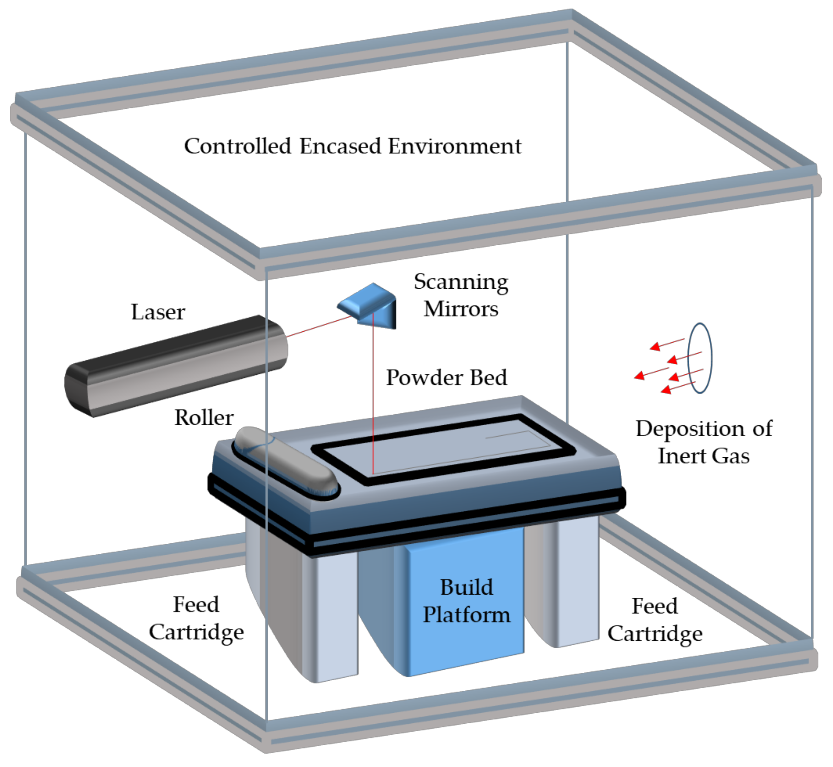
Figure 1. A schematic of a general powder bed fusion system, adapted with the permission of Ralls et al. [6].
Metals 12 01732 g001
Figure 2. A visual representation of the (a,b) binding (as shown in the yellow rectangle) and (c,d) porous defects induced from insufficient laser melting for 316L SS. The LED against part density is also shown (e) [38] Copyright 2022 Elsevier.
Metals 12 01732 g002
Figure 3. Various scanning directions used for 316L SS (ad) [76] and 304L SS (e) reprinted/adapted with permission from Fanshanu et al. [77].
Metals 12 01732 g003
Figure 4. The microstructural formation of 316L SS under (a) 75 μm, (b) 100 μm, (c) 150 μm, and (d) 200 μm hatch spacings as well as (e,f) the relation of temperature and time of the laser melted particles to their liquidus and solidus states [81].
Metals 12 01732 g004
Figure 5. The (a) epitaxial grain formation that governs anisotropic mechanical strength and its (b) performance under different polar angles [91].
Metals 12 01732 g005
Figure 6. The (a) stress-strain curves and fractography of SLM 316L SS at the LED of (b) 41.7 J/mm3, (c) 62.5 J/mm3, and, (d) 156.3 J/mm3 [92] Copyright 2022 Elsevier.
Metals 12 01732 g006
Figure 7. The relationship of laser energy density to microhardness for 316L SS [89,93,94,95].
Metals 12 01732 g007
Figure 8. The SEM images of the wear tracks for (a,b) FeCrMoVC steel, (c,d) 1.2379 steel, and (e,f) SLM FeCrMoVC steel [100] Copyright 2022 Elsevier.
Metals 12 01732 g008
Figure 9. SEM images of the wear track of SLM S136 steel in its (a) as-processed condition and with the addition of (b) 0.5 wt.%, (c) 1.5 wt.%, and (d) 2.5 wt.% TiB2 nanoparticles [101] Copyright 2022 Elsevier.
Metals 12 01732 g009
Figure 10. The (a) average COF, (b) COF over a sliding distance, and (c) wear rates of SLM 316L SS under different post-processing conditions. The worn surface morphology of the (d) conventional rolled 316L SS, (e) SLM 316L SS at 120 W and 100 mm/s scanning speed, (f) SLM’ed 316L SS at 120 W and 280 mm/s scanning speed, and the (g) EDS scan of the red box in portion [102].
Metals 12 01732 g010
Figure 11. The pitting mechanisms associated with SLM’ed 316L SS through the surface gas pores with (a) the initial formation of the passive film, to the transition of (b) pit nucleation and (c) pit diffusion, to the (d) stable growth the metastable pit and the (e) material degradation from the active state dissolution process [106] Copyright 2022 Elsevier.
Metals 12 01732 g011
Figure 12. The scanning strategies used by Zhao et al. [108] consist of an (a) °0, (b) 67.5°, and (c) 90° rotation along the (d) XY and XZ planes. The (e) OCP and (f) potentiodynamic polarization scans of the samples in NaCl 3.5 wt.% solution.
Metals 12 01732 g012
Table 1. Advantages and disadvantages of using SLM over traditional manufacturing techniques.
ApplicationAdvantage of SLM over Traditional Manufacturing TechniquesDisadvantage of SLM over Traditional Manufacturing TechniquesRef.
Automotive–Housing for Heat Emitting Components
  • Built-in cooling channels
  • Complex surface features to improve efficiency
  • Long build time
  • Inability to produce part(s) at a high volume at a reasonable cost
[26]
Aerospace–Unique and Complex Components
  • High precision
  • Tight dimensional tolerances
  • Rough surface finish
  • Varying porosity
[27,28]
Biomedical–Bone Implants
  • Imitate the porosity of human bones
  • Implementation of sub-mm features
  • Random porous deposits
  • Varying mechanical stability
[29]
Tooling and Dies–Pattern Manufacturing and Cutting Tools
  • High toughness from melting and fast cooling mechanism
  • Low production rates
  • High costs from necessary secondary processes
[30,31]
HVAC–Heat Exchangers
  • Built as a single unit
  • Ability to design layered thin wall designs
  • Rough surface finish increases the erosion rate of walls
[32,33]
Table 2. Various publications summarize SLMs effects on the mechanical properties of SLM-manufactured steels.
Article NameSummarizationReference
Study of mechanical properties of AISI 316 stainless steel processed by “selective laser melting”, following different manufacturing strategies
  • SLM-produced AISI 316L stainless steel samples produced with varying manufacturing orientation
  • Mechanical properties observed and compared to samples manufactured using wrought processes
  • High mechanical performance for the SLM parts was found while also maintaining high ductility and notch impact resistance
[88]
Microstructure and mechanical properties of 316L austenitic stainlesssteel processed by different SLM devices
  • The influence of different SLM devices on SLM-produced 316L stainless was studied
  • Optimized parameters set by each manufacturer were used
  • Different SLM types of machinery produced various porosities, despite using the same processing conditions
[56]
316L stainless steel mechanical and tribological behavior—A comparison between selective laser melting, hot pressing and conventional casting
  • 316L stainless steel was produced using SLM, hot pressing, and conventional casting
  • The highest mechanical properties observed were from the SLM-produced samples
  • The improved mechanical properties are a result of the finer microstructure achieved by SLM
[89]
Selective laser melting of HY100 steel: Process parameters, microstructure and mechanical properties
  • HY100 steel was produced using SLM with various combinations of laser power, scan speed, and hatch spacing
  • As-built samples were found to be unusable due to the brittle martensite microstructure
  • Significant anisotropy was observed concerning the build direction for the as-built samples
[96]
Selective laser melting of 304L stainless steel: Role of volumetric energy density on the microstructure, texture and mechanical properties
  • The impact of energy density was examined on 304L stainless steel samples
  • A linear relation between volumetric energy density and relative material density was found
  • Yield strength, ultimate tensile strength, and microhardness of the SLM samples were found to be greater than 304L samples produced using conventional means
[97]
Microstructure and Properties of Selective Laser MeltedHigh Hardness Tool Steel
  • X110CrMoVAl 8-2 tool steel was created using an SLM processes
  • The as-built samples displayed an irregular microstructure
  • After heat treatment, the SLM samples displayed similar hardness to conventionally produced X110CrMoVAl 8-2 but exhibited a finer microstructure
[98]
Investigation of effects of process parameters on microstructure and hardness of SLM manufactured SS316
  • Optimization of build densification for 316L stainless steel was observed
  • Energy density was found to heavily influence part porosity and hardness
  • Hardness was found to increase linearly with an increase in energy density
[93]
Table 3. Various publications summarize SLMs effects on the tribological properties of SLM-manufactured steels.
SummarizationReference
Sliding Wear Characteristics and Corrosion Behaviour of Selective Laser Melted 316L Stainless Steel
  • SLM 316L SS was fabricated and compared against wrought 316L SS
  • The wear volume of the SLM steel was reported to be 6–17 times greater
  • The increase in wear volume was attributed to the formation of porosity, as existing pores acted as crack initiation and propagation sights
[99]
Microstructure, mechanical behavior, and wear properties of FeCrMoVC steel prepared by selective laser melting and casting
  • SLM FeCrMoVC steel was fabricated and compared against casted FeCrMoVC steel
  • SLM steel had greater wear resistance
  • Micro-cutting and micro-plowing were primary wear mechanisms
  • Even distribution of M2C and MC carbides in the SLM steel improved its wear resistance
[100]
Tribology of selective laser melting processed parts: Stainless steel 316L under lubricated conditions
  • The tribological performance of SLM 316L SS and wrought 316L SS in lubricated conditions was observed
  • The friction and wear rate of the SLM steel was lesser than the wrought steel
  • Refined microstructure and increase in hardness were primary factors for the reduced wear rate
[76]
Enhanced hardness and wear property of S136 mould steel with nano-TiB2 composites fabricated by selective laser melting method
  • The tribological performance of SLM S136 mould steel with 0, 0.5, 1, and 1.5 wt. % TiB2 nanoparticles were observed
  • SLM component with 0.5 wt. % TiB2 nanoparticles had to greatest wear resistance
  • Further increasing the wt. % of particles resulted in delamination and spalling on the surface
[101]
Heat treatment effect on the microstructure, mechanical properties, and wear behaviors of stainless steel 316L prepared via selective laser melting
  • The tribological performance of SLM 316L SS components under furnace and hot isostatic pressing treatments were observed
  • COF was increased for both SLM samples after post-processing
  • Greater cumulative wear loss was observed due to the hardness decreasing after post-processing
[102]
Table 4. Various publications summarize SLMs effects on the corrosion performance of SLM-manufactured steels.
Article NameSummarizationReference
Electrochemical studies on the effect of residual stress on the corrosion of 316L manufactured by selective laser melting
  • The corrosion performance of SLM 316L SS was elucidated
  • SLM induced compressive stresses, which allowed for a more robust passive film
  • The pitting corrosion resistance was found to improve due to lesser point defect concentrations, which help prevent the penetration of Cl ions
[103]
On The Corrosion and Metastable Pitting Characteristics of 316L Stainless Steel Produced by Selective Laser Melting
  • The metastable pitting characteristics of SLM 316L SS were observed
  • It was found that the likelihood of stable pitting increased as the porous content of the SLM build increased
  • Pitting mechanisms were identified to be related to gas pores induced from the SLM process
[105]
Pitting behavior of SLM 316L stainless steel exposed to chloride environments with different aggressiveness: Pitting mechanism induced by gas pores
  • The transition of metastable pitting growth to stable pitting growth for SLM 316L SS was observed
  • The fil dissolution rate within surface pits determines the likelihood of metastable pitting
  • When metal dissolution begins to occur, the metastable pitting occurring on the surface will then be transitioned to stable pitting
[106]
On the enhanced corrosion resistance of a selective laser melted austenitic stainless steel
  • The pitting mechanism of SLM 316L SS compared to wrought 316L SS was compared
  • SLM 316L SS experienced greater pitting resistance due to the lack of MnS inclusions along the surface compared to wrought steel
  • These inclusions were eliminated due to the rapid solidification of the melted powder during melting
[107]
Influence of scanning strategy and building direction on microstructure and corrosion behaviour of selective laser melted 316L stainless steel
  • The corrosion resistance of SLM 316L SS as a function of building direction and scanning strategy was observed
  • Scanning at a 90° rotation resulted in the greatest corrosion resistance due to the complex crystallographic formation that occurred from the rapid heating and cooling process
  • Due to refined microstructure, greater native oxide film was formed along the surface
[108]
Mechanical properties and corrosion behavior of selective laser melted 316L stainless steel after different heat treatment processes
  • Post-processing heat treatments were applied to SLM 316L SS
  • Heat treatments were conducted at 1050 °C and 1200 °C followed by rapid water cooling
  • The dislocation density and degree of compressive residual stresses were decreased, which degraded the corrosion resistance
[109]
Publisher’s Note: MDPI stays neutral with regard to jurisdictional claims in published maps and institutional affiliations.