Article

Thermal Performance of the Thin Heat Pipe for Cooling of Solid-State Drives

1
College of Mechanical and Electronic Engineering, Nanjing Forestry University, Nanjing 210037, China
2
College of Mechanical and Electronical Engineering, Nanjing University of Aeronautics and Astronautics, Nanjing 210016, China
*
Author to whom correspondence should be addressed.
Metals 2022, 12(11), 1786; https://doi.org/10.3390/met12111786
Submission received: 8 September 2022 / Revised: 16 October 2022 / Accepted: 21 October 2022 / Published: 23 October 2022
(This article belongs to the Special Issue Ultra-Thin and Micro Heat Pipe Manufacturing and Their Applications)

Abstract

:
With the rapid development of information science and technology, the demand for computer data processing is increasing, resulting in the rapid growth of the demand for high-power and high-performance solid-state drives (SSDs). The stable operation of SSDs plays an important role in ensuring the reliable working conditions and appropriate temperature of information technology equipment, rack servers, and related facilities. However, SSDs usually have significant heat emissions, putting forward higher requirements for temperature and humidity control, and consequently the heat sink system for cooling is essential to maintain the proper working state of SSDs. In this paper, a new type of thin heat pipe (THP) heat sink is proposed, and the heat transfer performance and cooling effect are experimentally and numerically studied. The numerical results are compared with experimental results, which showed an error within 5%. Single and double heat pipes were investigated under different input powers (from 5 W to 50 W) and different placement angles between 0° and 90°. The heat transfer performance of the new heat sink is analyzed by the startup performance, the evaporator temperature, and the total thermal resistance. The results show that the new double THPs with a 90° angle have a great advantage in the heat transfer performance of SSDs. The research is of great significance for the design and optimization of the SSDs’ cooling system in practical applications.

1. Introduction

In recent years, the rapid progress in semiconductor materials and micro/nanomanufacturing technology has promoted the high integration, high frequency, high power, and miniaturization of electronic devices. Moore’s law states that as integrated circuits become more efficient, smaller, and faster, the number of transistors in the microprocessors increases exponentially [1,2,3]. Therefore, with the continuous progress of electronic system technology and the increasing demand for information processing, a higher power consumption of electronic components has been promoted, and the technical requirements for high temperature operation and heat exchange of electronic components have been continuously improved [4]. However, when the heat source is highly concentrated in small integrated electronic components, the improper heat exchange management of the electronic components will lead to serious damage to the functions of the integrated circuits, or even complete shutdown [5]. The demand for high performance makes most electronic components operate under the limitations of existing heat exchange management technology. Heat exchange management technology plays a key role in the continuous miniaturization, performance improvement, and higher reliability of electronic systems [6].
As electronic system technology advances, continual increases in requirements have led to higher power consumption, causing an increasing demand for thermal engineering and heat rejection technologies. The increasing demand for computer data processing has led to the rapid growth of SSDs with high performance and reliability in IT equipment, rack servers, and related equipment [7]. Generally speaking, the two main heat sources that generate heat in a computer workstation are the CPU and the graphics card [8]. Using a special radiator to transfer heat between the CPU and the graphics card, the fan and radiator components in the chassis form a reasonable chassis air duct, so the air flow in the chassis can flow normally according to a certain trajectory, and thus the system can operate stably at a normal temperature, while the heat dissipation of the SSD in the chassis is often ignored [9].
SSDs are important accessories for assembling computers; compared to traditional mechanical hard disks, solid state drives based on NAND flash memory provide an attractive storage solution. Compared to traditional hard disks, SSDs have higher speed and lower power consumption, which is well received by users, with a strong read–write performance and lightweight appearance [10,11]. In the process of high-speed reading and writing, it is inevitable to encounter the problem of SSDs heating, which is often ignored. Consequently, the heat source of the SSD is concentrated on master control panels and NAND particles due to their small size [12]. Long-term high-speed data reading and writing will cause heat accumulation in the processing area, resulting in the rise in the temperature of the SSDs [13]. Due to the surrounding environment, the size of the heat dissipation space, and other factors, it is hard to dissipate from the SSDs, which means the hard disk keeps working at a high temperature for a long time. In the long run, this will cause irreparable damage to the SSDs, and even affect the service life of the product. In the process of storage and writing, the thermal effect cannot be ignored when estimating the data retention time of NAND flash memory [14]. Therefore, the heat dissipation of SSDs should not be ignored. Generally, the appropriate working temperature for SSDs is about 50~55 °C. However, the normal working temperature of many SSDs in the market is maintained between 0 and 70 °C. When the temperature of the SSDs is too high, it will seriously lower the speed of the hard disk. A serious speed loss in the hard disk will lead to the whole system crashing [15]. For the safe and effective operation of microprocessors, the SSDs chips’ temperature needs to be kept below a critical value, so effective heat exchange management has become a problem that must be solved in advance [16].
In other applications such as electronics, the heat generated by components of electronic circuits (such as transistors and SSDs) is enough to affect the performance and durability of the equipment. Therefore, for the general aim of electronic cooling, various technologies are used, including natural convection heat sink [17], forced convection radiator [18], heat pipe (HP) cooling [19], liquid cooling [20], thermosyphon [21], and single-phase/two-phase cold plate cooling [22]. Among the above technologies, the heat pipe heat sink is widely used due to its simple structure and high heat exchange efficiency [23]. Therefore, considering the structure of the SSDs, thin heat pipes with high heat transfer coefficients are more suitable for the cooling of SSDs.
In recent decades, thermal management has become an important part of electrical, thermal mechanical, cutting processes, and so on [24,25]. Thin heat pipes (THPs) are known for their heat transfer capacity. They transfer heat through phase changes of the working fluid in the pipe without any additional power. Koito, Y. et al. introduced the ultra-THPs with a thickness below 1.0 mm which have been used for the thermal management of thin electronic devices such as smartphones [26]. Zhou, W. and Li, Y. investigated the novel ultra-thin loop heat pipe (UT-LHP) with capillary wick structures developed for mobile electronics’ cooling [27]. Chen, A. et al. used ultra-thin flattened heat pipes for cooling high-heat-flux electronic devices [28]. Research has shown that thermal management with heat pipes has a great potential in energy saving and green manufacturing [29].
The THP heat sink designed in this paper is very compact and steady. Moreover, it transfers heat through the phase change inside it; thus, no extra power is needed, which makes it practical to be applied in real devices. Compared with the plate–fin sink connected to the SSD’s surface, the heat pipe heat sink adopted in this experiment has the following advantages: First, the heat pipe sink is highly efficient, which can simplify the heat dissipation design of electronic equipment and change air cooling to self-cooling. Second, the heat pipe sink’s response speed is faster, and the thermal conductivity is more efficient than the plate–fin heat sinks. Finally, the heat pipe has good isothermal properties. After heat balance, the temperature gradient of the heat pipe evaporator and condenser is relatively small. Considering the high heat transfer capacity of the THP, this paper proposes a new method by incorporating the THP onto SSDs. The heat pipe and fin are innovatively integrated into one, which means the structure of the THP is more compact. Additionally, compared to other available cooling equipment and electronic equipment, the THP has a higher heat transfer performance, which greatly reduces the probability of SSDs failure in the actual process of using electronic equipment. The purpose of this research is to design a new type of SSDs heat sink. The thermal performance of the heat sink is experimentally studied. Factors such as the input heat power, the number of THPs, and the placement angles of the heat sink are studied. The experimental investigation aims to provide a prospect of THPs for the thermal management of SSDs in order to reduce the incidence of overheating when writing and reading data from SSDs [30]. The research has important implications for the design and optimization of SSDs’ cooling systems in practical applications.

2. Materials and Methods

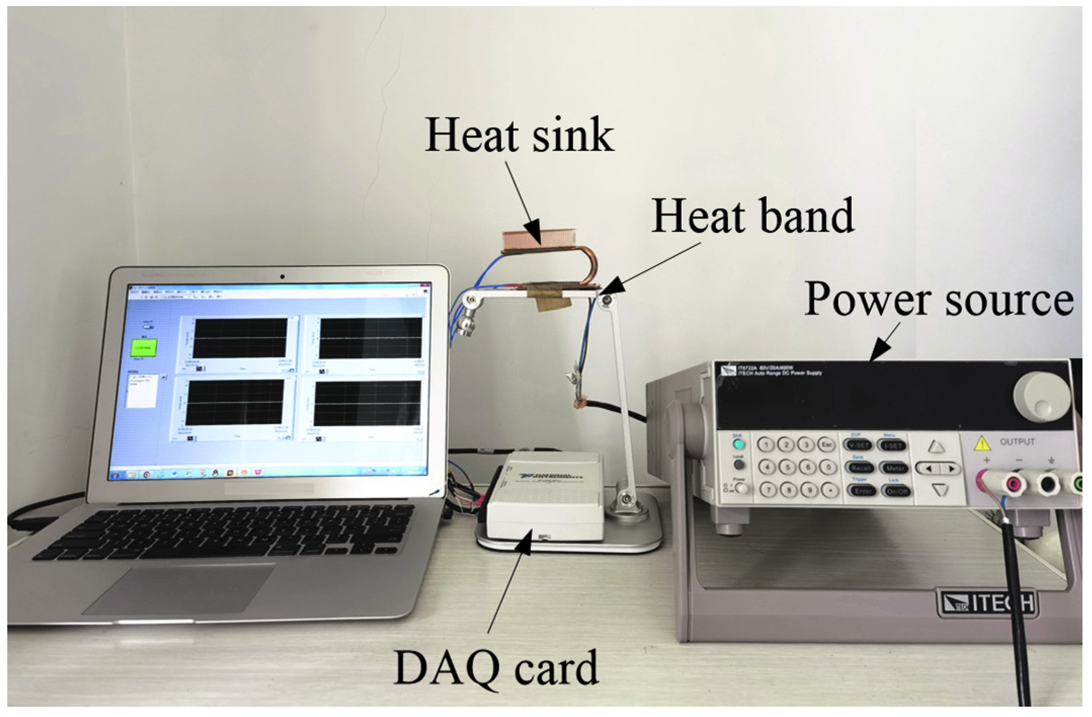
2.1. Experiment Methods and Conditions

Figure 1 shows the heat transfer principle of the heat sink for SSDs’ cooling. The new solid-state disk heat sink is composed of three parts: U-shaped THPs, copper fins, and a copper plate. The THPs are welded onto the copper plate, which is directly in contact with the SSDs. The part connected with the copper plate is the evaporator and the part connected with the copper fin is the condenser. All parts of the heat sink are made of copper, which has better thermal conductivity. When operating, the heat enters the evaporator section of the THPs through the heat conduction by the copper plate, and the internal working medium undergoes phase change and movement towards the condenser section under the action of the pressure difference, where it condenses as it reaches the condenser and flows back to the evaporator, completing the thermal dynamic cycle. Specific dimensional details of the THPs are shown in Table 1.
Figure 2 shows the heat transfer performance test platform of the THP heat sink. The heat transfer test platform includes a power source, a heat band, and a DAQ card. There are some specifications for each device we have used. The HP model is a sintered copper–water flat heat pipe. The heat pipe’s cross section (L × H) is 7 × 0.4 mm. The power supply is a programmable DC power supply with the model of IT6722A. The model of SSD is Samsung 980 (Samsung, Seoul, Korea), and the size of SSD (L × W × H) is 80 × 22 × 2 mm. The DAQ model is NI 6211, and the sampling frequency is 250 kS/s. The SSD’s heat sink is installed on the heat band. K-type thermocouples are arranged on the evaporator and condenser end of the THP to monitor the temperature, which are denoted as Te and Tc, respectively. The diameter of the thermocouples is 0.25 mm, and they are Teflon-coated. The most important point is that the THPs and copper plate are integrated. The band heater and copper plate are coated with thermal grease and glued together by high temperature insulation tape, so heat loss can be ignored. The input power used in the study ranges from 5 to 50 W. The working fluid of the SSD’s THP heat sink is deionized water, and the liquid filling ratio is 10%. The condenser is cooled by a normal air fan. The fan is blown directly against the fins and the distance is 10 mm. The two thermocouples in Figure 1 are each welded in the middle of the upper and lower parts of the thin sheet heat pipe. The brazing is insulated around it. We install the belt heater through Teflon high temperature tape, model 3J730, with high temperature resistance of 250 °C to 300 °C, and the thermal conductivity of the tape is 8.5 W/m·K. The schematic diagrams in the paper are all designed to show the structure of the THP heat sink more clearly. During the experiment, the copper platform, copper fin, and thin-walled heat pipe are insulated to ensure the heat input of the heating pipe. In the experiment, the heat transfer capacity of the THP heat sink was analyzed for two placement angles of 0° and 90°, as shown in Figure 3. Both single and double THPs will be analyzed to study the influence of the heat pipe quantities, as shown in Figure 4. Specific test parameters are shown in Table 2.

2.2. Data Processing and Uncertainty Analysis

The heat transfer performance of the heat sink was evaluated by thermal resistance, which is calculated by:
R = (TeTc)/Q
where Te and Tc refer to the temperature on the evaporator and condenser, and Q is the heat input. Since insulation measures have been taken for the heat sink, the heat loss was ignored. Thus, the heat input equals the heating power, and is determined by:
Q = UI
U and I are the output voltage value and current value of the IT6722A DC power supply, which have an accuracy of ±0.01% and ±0.1%, respectively. The accuracy of the K-type thermocouple is ±1.2%. Considering the accuracy of the data acquisition card and the related parameters, the maximum uncertainty of the thermal resistance was about 1.7, which was obtained according to the principle of error propagation and composition [31]. Details are shown in Table 3.

3. Experimental Results and Discussion

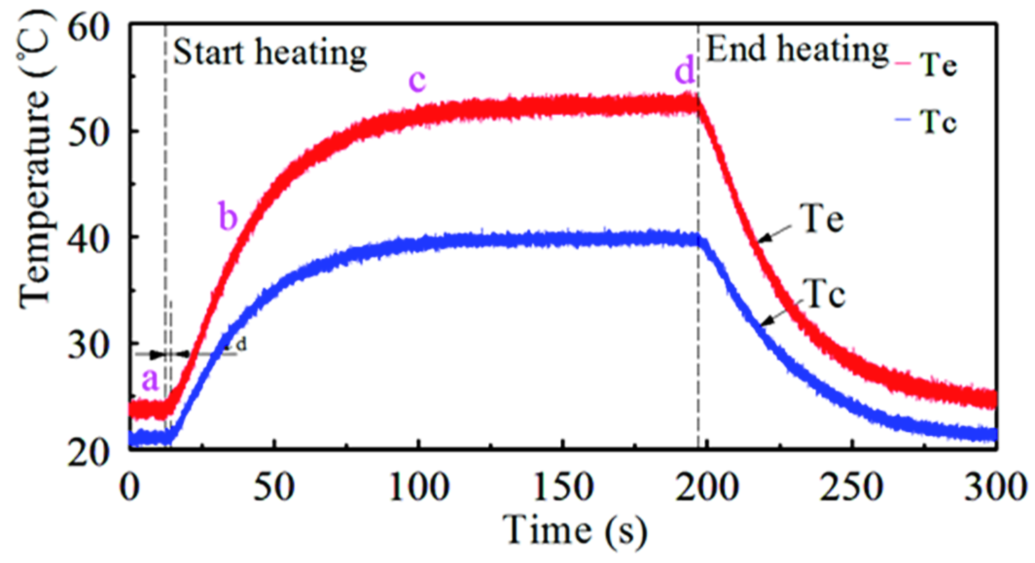
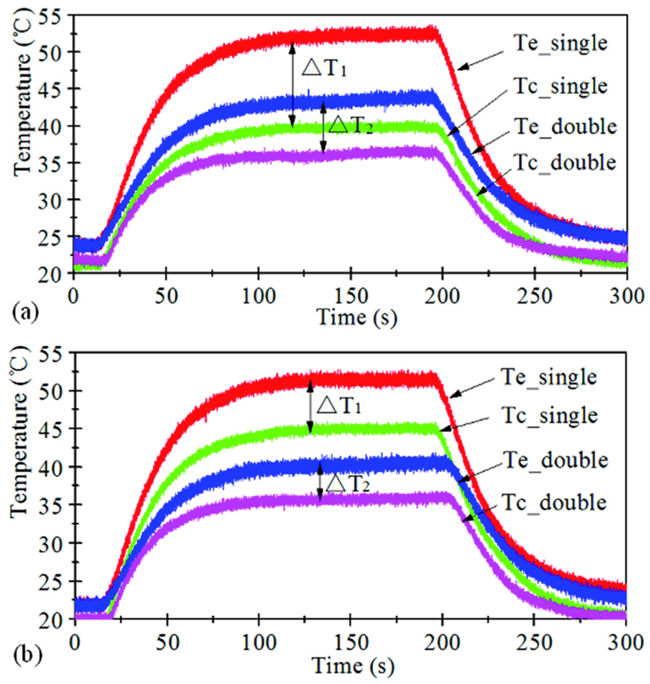
3.1. Startup Performance of SSD Heat Sink

Figure 5 shows the temperature variation curve outside the evaporator and the condenser section of the SSD heat sink under the condition of 50 W of heat input. A single THP with a placement position of 0° is applied. The process includes three stages: linear temperature rises (ab segment), nonlinear temperature rises (bc segment), and the stable stage (cd segment). The initial temperature outside the evaporator rises linearly mainly due to the heat conduction of the copper matrix. Due to the fact that the heating coil is covered by thermal insulation material, the heat convection with the surroundings and the radiation were ignored here. After point b, due to the phase change in the THP and the convection heat transfer between the fins and the air, the SSD sink possesses a more prominent thermal enhancement; therefore, the temperature rise rate is lowered, and thus a nonlinear temperature rise appears. After point c, the temperature outside the evaporator and the condenser is stable, and the temperature difference between Tc and Te is stable too. When the heat source is turned off, both temperatures decrease gradually until they reach the ambient temperature.
It can be seen from the chart that a delay time td occurs between Te and Tc, because it takes a certain time for the input heat to be transferred to the condenser section. In this case, the total starts up process takes about 90 s.

3.2. Effect of Working Parameters
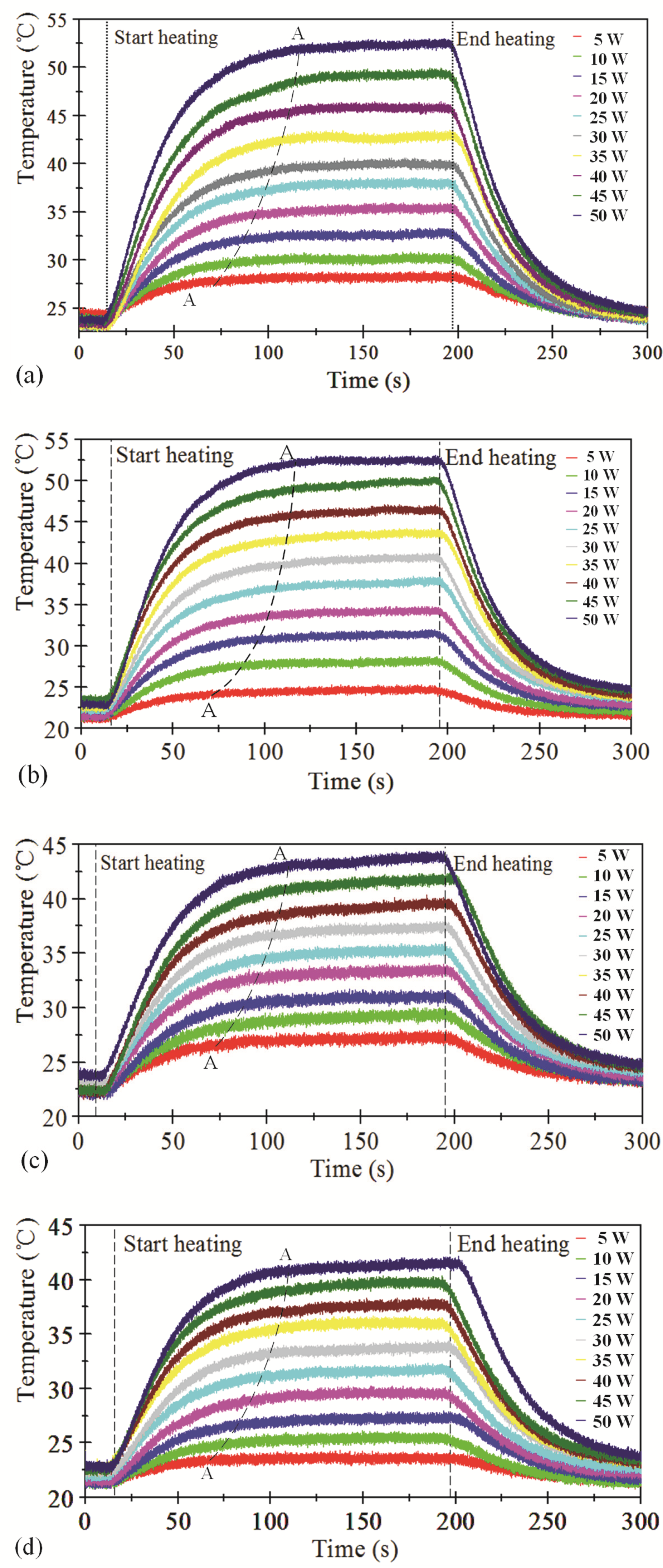
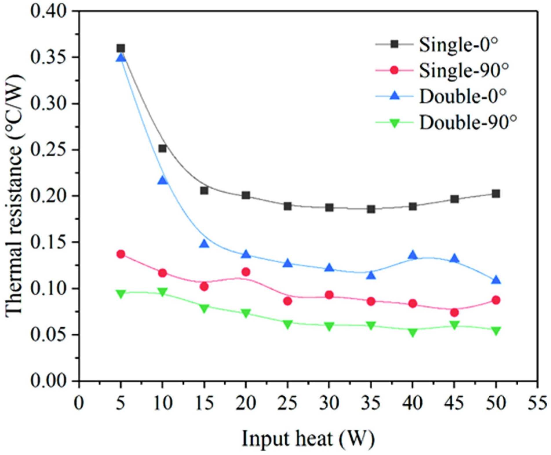
3.2.1. Heat Input

Figure 6 demonstrates the temperature outside the evaporator with the increase in the heat input. Te increases with the rise in the input heat. The figure “A–A” shows the curve of the evaporator of the heat pipe sink reaching a steady state for different input powers. A similar tendency with three stages of temperature rise was found for different cases. Moreover, it can be noticed that the start-up time for the heat sink increases with the increase in the input heat.
The thermal resistance under different cases is shown in Figure 7. Generally, the thermal resistance decreases with the increase in the input heat, which may be caused by a more violent convection and phase change heat transfer. Compared to the single THP, double THPs show better heat transfer performance for each position angle. It can be noticed that, as the THPs are placed at 90°, the thermal resistance is smaller than when placed at 0°. Additionally, the heat sink with single THP placed at 90° exhibits a lower thermal resistance than that with double THPs placed at 0°. This means the effect of the location is more significant. As the heat input ranges from 0 to 15 W, the thermal resistance reduction trend of the heat pipe placed at 0° is more evident, which decreases by about 42.7% and 57.5% for the single and double THPs, respectively. While the thermal resistance for the heat sink placed at 90° shows more stability, it reveals that the heat transfer performance of the SSD heat sink placed at 90° is more efficient and stable. This can be attributed to the lower flow resistance when the heat sink is placed at 90°. Due to the obstruction of gravity, the movement of the working medium in the THP placed at 0° is more difficult, resulting in a worse heat transfer capacity. As a result, the SSD heat sink placed at 90° has a lower thermal resistance and a more efficient and stable heat transfer performance.

3.2.2. Quantities of THP

As shown in Figure 8, under the input heat of 50 W, the comparison between single THP and double THPs were discussed. When the heat sinks were placed at 0°, the temperature difference between the evaporator and condenser section for both heat sinks with single THP and double THPs are displayed in Figure 8a. Where Te and Tc refer to the temperature on the evaporator and condenser, the temperature values of Te and Tc are determined by the steady state temperature of the evaporator and the condenser of the heat sink. The temperature difference for the heat sink with double THPs is about 4.69 °C lower than that with single THP, corresponding to a lower thermal resistance by about 46.4%. Figure 8b shows the results with the heat sinks placed at 90°. The temperature difference for the heat sink with double THPs is about 1.61 °C lower than that with single THP, corresponding to a lower thermal resistance by about 36.7%. Therefore, double THPs exhibit a better heat transfer performance.

3.2.3. Position of the Heat Sink

Figure 9 shows the temperature curves for different placement angles. Double THPs were applied with an input heat of 50 W. Similar variations of the temperatures are found, reflecting the same heat transfer mechanism. For the position angle at 0°, the temperature difference ΔT1 is much bigger than that with a position angle at 90° (ΔT2), corresponding to an increase in thermal resistance by about 48.9%. This result should be attributed to the higher flow resistance caused by the combination of gravity and the abrupt change of the flow direction as the THP was positioned at an angle of 0°. In this case, it is difficult to transfer the vapor to the condenser as the flow direction changes by 180° at the corner between the evaporator and the condenser. Moreover, it should also be noted that the delay time for the temperature rise of Tc is longer for the THPs at a placement angle of 0°, which also verified the higher flow resistance at the placement angle of 0°.

3.3. Simulation for the SSD Heat Sink

3.3.1. Simulation Parameters

As experimental studies incur time and cost, a numerical analysis of heat sink designs was carried out to achieve the better design. In addition, numerical modeling results are compared by experiments, and numerical analysis helps to understand the thermal behavior in the heat sink. The computational domain with boundary conditions is shown in Figure 10. The new double THPs heat sink is mainly composed of three parts: a metal platform as the heat source at the bottom of the evaporation end, double thin heat pipes, and the flat heat fin.
The bottom of a copper platform acts as a constant heat source in the range of 5–50 W, with a corresponding heat flux of 1600–16,000 W/m2. Due to the fact that the top surface of the copper plate is adiabatic during the experiment, the top surface of the copper plate that is not in contact with the heat pipe is set as the adiabatic. The double thin heat pipes are the adiabatic end of the coupled heat transfer. The adiabatic wall condition was applied to the heat pipes, as shown in Figure 10. The double thin heat pipes conduct coupled heat transfer with the heat source at the condenser fin and the evaporator, respectively. The fin at the condenser transfers the heat coupled to the heat pipe through convection heat transfer with air-to-heat circulation. The gravity was set as 9.8 m/s2 along the −z direction. The simulation software simultaneously solved the continuity, momentum, and energy equations to predict the velocity, pressure, and temperature distributions.
The details of the copper matrix were defined as shown in Table 4. Therefore, the thermal conductivity of 387.6 W/m·K is obtained according to the properties of copper. Note that the thermal conductivity of the heat fin was taken as 420 W/m2·K, so the convective heat transfer coefficient at the condenser is 420 W/m2·K. The standard K-ε turbulence model is used as the solution model for the forced convective heat transfer on the outer wall of the finning tube. The initial temperature of the new type of thin heat pipe (THP) heat sink was set as 293.15 K.

3.3.2. Simulation Results

The final temperature contours of the double THPs heat sink with different input powers are shown in Figure 11. Figure 11 shows the temperature distribution cloud diagram of the double THPs heat sink under the steady state of numerical simulation. The heat pipe is placed at 90°. It can be clearly seen that heat is conducted to the evaporator section through the bottom of the heating plate. The heat is then transferred to the condenser section, resulting in a local temperature rise. After a period of time, the temperature on the heat sink and the ambient temperature reaches a stable state.
The temperature recorded in Table 5 is the steady-state temperature Te of the double THPs heat sink under experiment and simulation. As can be seen in Table 5, the experiment results and simulation results are compared in terms of the temperature outside the evaporator. The maximum temperature difference between the observed and simulated values of the heat sink was 3.53%; therefore, the experiment results are reliable.

4. Conclusions

To solve the overheating problem of SSDs in current research, THP was applied to improve the SSD’s heat transfer. The number of heat pipes and the placement angle of the heat sink were studied. The simulation analysis was applied and compared with experimental results to further confirm the heat transfer advantage of the THPs in SSDs. The main conclusions are as follows:
(1) The heat transfer process of the new THP heat sink includes three stages: linear temperature rises; nonlinear temperature rises, and the stable stage. For the single THP heat sink with an input heat of 50 W, the whole start-up process takes about 90 s.
(2) The thermal resistance decreases with the increase in input heat, which may be caused by more violent convection and phase change heat transfer. As the input heat ranges from 0 to 15 W, the thermal resistance reduction trend of the heat sink placed at 0° is more evident, which decreases by about 42.7% and 57.5% for the heat sink with single and double THPs, respectively.
(3) The heat transfer performance of the SSD’s heat sink placed at 90° is more efficient and stable. As the heat sinks with double THPs placed at 90°, the thermal resistance can be lowered by about 48.9% compared to that placed at 0° under the heat input of 50 W.
(4) The heat sink with double THPs exhibits better heat transfer performance with lower thermal resistance by about 46.4% and 36.7% when placed at 0° and 90°, respectively.
(5) The simulation results are in accordance with the experimental results with a maximum temperature error of about 3.53%.
(6) Compared to other THPs, the heat sink with double THPs placed at 90° has great application potential. The evaporator temperature can be kept below 45 °C to ensure the SSD can safely read and store data and the total thermal resistance can be maintained between 0.05 and 0.1 for a better heat transfer performance of the heat sink.

Author Contributions

Conceptualization, J.C. and N.Q.; methodology, H.J. and Y.Y.; Writing, D.Y. and J.C.; investigation, D.Y., S.L. and J.C.; data analysis, L.Z. and D.Y. All authors have read and agreed to the published version of the manuscript.

Funding

This research was funded by National Natural Science Foundation of China [51905275], National Natural Science Foundation of China [52205476], Natural Science Foundation of Jiangsu Province [BK20190752], Natural Science Research of Jiangsu Higher Education Institutions of China [19KJB460020], China Postdoctoral Science Foundation [2021M701696] and Outstanding Postdoctoral Program of Jiangsu Province [2022ZB204].

Data Availability Statement

Not applicable.

Conflicts of Interest

The authors declare no conflict of interest.

References

  1. Ajayan, J.; Nirmal, D.; Tayal, S.; Bhattacharya, S.; Arivazhagan, L.; Fletcher, A.S.A.; Muruga Pandiyan, P.; Ajitha, D. Nanosheet field effect transistors—A next generation device to keep Moore’s law alive: An intensive study. Microelectron. J. 2021, 114, 105141. [Google Scholar] [CrossRef]
  2. Jiang, D.; Liu, S.; Tang, W. Fabrication and Manipulation of Non-Spherical Particles in Microfluidic Channels: A Review. Micromachines 2022, 13, 1659. [Google Scholar] [CrossRef]
  3. Ho, C.J.; Liu, Y.C.; Ghalambaz, M.; Yan, W.-M. Forced convection heat transfer of Nano-Encapsulated Phase Change Material (NEPCM) suspension in a mini-channel heatsink. Int. J. Heat Mass Transf. 2020, 155, 119858. [Google Scholar] [CrossRef]
  4. Salman, O.H.; Taha, Z.; Al-Sabah, M.Q.; Hussein, Y.S.; Mohammed, A.S.; Aal-Nouman, M. A review on utilizing machine learning technology in the fields of electronic emergency triage and patient priority systems in telemedicine: Coherent taxonomy, motivations, open research challenges and recommendations for intelligent future work. Comput. Methods Programs Biomed. 2021, 209, 106357. [Google Scholar] [CrossRef] [PubMed]
  5. Jayaramu, P.; Gedupudi, S.; Das, S.K. Experimental investigation of the influence of boiling-induced ageing on high heat flux flow boiling in a copper microchannel. Int. J. Heat Mass Transf. 2021, 181, 121862. [Google Scholar]
  6. Bailey, C. Thermal Management Technologies for Electronic Packaging: Current Capabilities and Future Challenges for Modelling Tools. In Proceedings of the EPTC: 2008 10th Electronic Packaging Technology Conference, Singapore, 9–12 December 2008; Volume 1–3, pp. 527–532. [Google Scholar]
  7. Iturriaga, S.; Nesmachnow, S. Scheduling Energy Efficient Data Centers Using Renewable Energy. Electronics 2016, 5, 71. [Google Scholar] [CrossRef] [Green Version]
  8. Zhao, N.; Qi, C.; Chen, T.; Tang, J.; Cui, X. Experimental study on influences of cylindrical grooves on thermal efficiency, exergy efficiency and entropy generation of CPU cooled by nanofluids. Int. J. Heat Mass Transf. 2019, 135, 16–32. [Google Scholar] [CrossRef]
  9. Korpyś, M.; Al-Rashed, M.; Dzido, G.; Wójcik, J. CPU Heat Sink Cooled by Nanofluids and Water: Experimental and Numerical Study. In Proceedings of the 23rd European Symposium on Computer Aided Process Engineering, Lappeenranta, Finland, 9–12 June 2013; pp. 409–414. [Google Scholar]
  10. Solodov, D.; Solodov, I. Data recovery in a case of fire-damaged Hard Disk Drives and SSDs. Forensic Sci. Int. Rep. 2021, 3, 100199. [Google Scholar] [CrossRef]
  11. Farjallah, E.; Armani, J.M.; Gherman, V.; Dilillo, L. Improvement of the tolerated raw bit error rate in NAND flash-based SSDs with selective refresh. Microelectron. Reliab. 2019, 96, 37–45. [Google Scholar] [CrossRef]
  12. Fukami, A.; Ghose, S.; Luo, Y.; Cai, Y.; Mutlu, O. Improving the reliability of chip-off forensic analysis of NAND flash memory devices. Digit. Investig. 2017, 20, S1–S11. [Google Scholar] [CrossRef]
  13. Tokutomi, T.; Tanakamaru, S.; Iwasaki, T.O.; Takeuchi, K. Advanced error-prediction LDPC with temperature compensation for highly reliable SSDs. Solid-State Electron. 2015, 111, 129–140. [Google Scholar] [CrossRef]
  14. Coutet, J.; Marc, F.; Dozolme, F.; Guétard, R.; Janvresse, A.; Lebossé, P.; Pastre, A.; Clement, J.C. Influence of temperature of storage, write and read operations on multiple level cells NAND flash memories. Microelectron. Reliab. 2018, 88–90, 61–66. [Google Scholar] [CrossRef]
  15. Kim, M.; Chun, M.; Hong, D.; Kim, Y.; Cho, G.; Lee, D.; Kim, J. RealWear: Improving performance and lifetime of SSDs using a NAND aging marker. Perform. Eval. 2021, 145, 102153. [Google Scholar] [CrossRef]
  16. Kumar, A.; Kothari, R.; Sahu, S.K.; Kundalwal, S.I. A comparative study and optimization of phase change material-based heat sinks for thermal management of electronic components. J. Energy Storage 2021, 43, 103224. [Google Scholar] [CrossRef]
  17. Huang, C.H.; Wu, Y.T. An optimum design for a natural convection pin fin array with orientation consideration. Appl. Therm. Eng. 2021, 188, 116633. [Google Scholar] [CrossRef]
  18. Lee, I.; Kim, S.J. Topology optimization of a heat sink with an axially uniform cross-section cooled by forced convection. Int. J. Heat Mass Transf. 2021, 168, 120732. [Google Scholar] [CrossRef]
  19. Veerasamy, A.; Balakrishnan, K.; Abdul Razack, S. Performance of heat pipe with nanorefrigerant in electronic cooling applications. Mater. Today Proc. 2022, 65, 375–379. [Google Scholar] [CrossRef]
  20. Koukoravas, T.P.; Damoulakis, G.; Megaridis, C.M. Experimental investigation of a vapor chamber featuring wettability-patterned surfaces. Appl. Therm. Eng. 2020, 178, 115522. [Google Scholar] [CrossRef]
  21. Anand, R.S.; Jawahar, C.P.; Brusly Solomon, A.; David, S.; Bellos, E.; Said, Z. Experimental investigations on modified thermosyphons using R134a/Al2O3 and comparative machine learning analysis. Appl. Therm. Eng. 2022, 212, 118554. [Google Scholar] [CrossRef]
  22. Paniagua-Guerra, L.E.; Sehgal, S.; Gonzalez-Valle, C.U.; Ramos-Alvarado, B. Fractal channel manifolds for microjet liquid-cooled heat sinks. Int. J. Heat Mass Transf. 2019, 138, 257–266. [Google Scholar] [CrossRef]
  23. Gorzin, M.; Ranjbar, A.A.; Hosseini, M.J. Experimental and numerical investigation on thermal and hydraulic performance of novel serpentine minichannel heat sink for liquid CPU cooling. Energy Rep. 2022, 8, 3375–3385. [Google Scholar] [CrossRef]
  24. Wei, W.H.; Shang, Y.Y.; Peng, Y.; Cong, R. Research Progress of Noise in High-Speed Cutting Machining. Sensors 2022, 22, 3851. [Google Scholar] [CrossRef]
  25. Jia, X.D.; Zhou, Y.; Wang, Y.N. Deformation Behavior and Constitutive Model of 34CrNi3Mo during Thermo-Mechanical Deformation Process. Materials 2022, 15, 5220. [Google Scholar] [CrossRef]
  26. Koito, Y. Numerical analyses on heat transfer characteristics of ultra-THPs: Fundamental studies with a three-dimensional thermal-fluid model. Appl. Therm. Eng. 2019, 148, 430–437. [Google Scholar] [CrossRef]
  27. Zhou, W.; Li, Y.; Chen, Z.; Deng, L.; Gan, Y. A novel ultra-thin flattened heat pipe with biporous spiral woven mesh wick for cooling electronic devices. Energy Convers. Manag. 2019, 180, 769–783. [Google Scholar] [CrossRef]
  28. Chen, A.; Jiang, F.; Dong, J.; Chen, J.; Zhu, Y. Design, fabrication and thermal performance of a novel ultra-thin loop heat pipe with printed wick structure for mobile electronics cooling. Appl. Therm. Eng. 2022, 200, 117683. [Google Scholar] [CrossRef]
  29. Ji, Y.; Yuan, D.; Hao, Y.; Tian, Z.; Lou, J.; Wu, Y. Experimental study on heat transfer performance of high temperature heat pipe with large length-diameter ratio for heat utilization of concentrated solar energy. Appl. Therm. Eng. 2022, 215, 118918. [Google Scholar] [CrossRef]
  30. Lee, K.; Kang, M.; Hwang, Y.; Shin, H. Accurate Lifetime Estimation of Sub-20-nm NAND Flash Memory. IEEE Trans. Electron Devices 2016, 63, 659–667. [Google Scholar] [CrossRef]
  31. Ho, C.J.; Liu, Y.C.; Yang, T.F.; Ghalambaz, M.; Yan, W.M. Convective heat transfer of nano-encapsulated phase change material suspension in a divergent minichannel heatsink. Int. J. Heat Mass Transf. 2021, 165, 120717. [Google Scholar] [CrossRef]
Figure 1. Schematic diagram of THP heat sink for cooling of SSDs.
Metals 12 01786 g001
Figure 2. The composition of the heat transfer test platform.
Metals 12 01786 g002
Figure 3. Position of the heat sink: (a) 0°; (b) 90°.
Metals 12 01786 g003
Figure 4. Heat sinks used for cooling (a) single THP; (b) double THPs.
Metals 12 01786 g004
Figure 5. Temperature outside the evaporator and condenser section.
Metals 12 01786 g005
Figure 6. Temperature outside the evaporator of the heat sink under different heat inputs for different cases of (a) single THP with 0°; (b) single THP with 90°; (c) double THPs with 0°; (d) double THPs with 90°.
Metals 12 01786 g006
Figure 7. The thermal resistance of the SSD heat sink under different heat inputs.
Metals 12 01786 g007
Figure 8. Temperature outside the evaporator and condenser for heat sinks placed at (a) 0° and (b) 90°.
Metals 12 01786 g008
Figure 9. Thermal performance comparison between 0°and 90°.
Metals 12 01786 g009
Figure 10. Computational domain with boundary conditions.
Metals 12 01786 g010
Figure 11. Temperature contours for the heat sink at different inputs.
Metals 12 01786 g011
Table 1. Dimensional details of the THPs.
Dimension ParametersValue (mm)
SSD (L × W × H)80 × 22 × 2
Copper plate (L × W × H)70 × 20 × 1
Band heater (L × W)70 × 20
Heat pipe cross section (L × H)7 × 0.4
Copper fin (L × W × H)61 × 25 × 19
Fin spacing2
Table 2. Heat transfer test parameters.
ParameterValue
Heat input Q (W)5; 10; 15; 20; 25; 30; 35; 40; 45; 50
Position of the heat sink0°; 90°
Filling ratio φ (%)10%
Working fluid typeDeionized water
Cooling air temperature for the condenser20 °C
Table 3. Maximum uncertainty of the main measurement parameters.
ParameterTeTcUIQR
Maximum uncertainty (%)±1.2±1.2±0.01±0.10.11.7
Table 4. The details of the copper matrix.
ItemsParameters
MaterialCoppers
Density (kg/m3)8978
Cp (Specific Heat) (J/kg·K)381
Thermal Conductivity (W/m·K)387.6
Table 5. Comparison between the experiment and simulation results.
Heat Input (W)Simulation Results (T1/°C)Experiment Results (T2/°C)Error (M/%)
526.8126.970.59
1029.3829.180.68
1531.5130.892.01
2032.74330.76
2534.2134.751.55
3035.6836.482.19
3537.9738.260.76
4039.1340.062.32
4541.6242.231.37
5042.1243.663.53
Publisher’s Note: MDPI stays neutral with regard to jurisdictional claims in published maps and institutional affiliations.

