Article

Effect of Structural Induced Stress on Creep of P92 Steel Pipe to Elbow Welds

1
Datang Boiler Pressure Vessel Inspection Center Co., Ltd., Hefei 230088, China
2
East China Electric Power Test and Research Institute, China Datang Corporation Science and Technology Research General Institute Co., Ltd., Hefei 230088, China
3
School of Material Science and Engineering, Anhui University of Technology, Ma’anshan 243032, China
*
Author to whom correspondence should be addressed.
Metals 2022, 12(11), 1792; https://doi.org/10.3390/met12111792
Submission received: 22 August 2022 / Revised: 30 September 2022 / Accepted: 3 October 2022 / Published: 24 October 2022
(This article belongs to the Special Issue Welding and Joining of Dissimilar Materials)

Abstract

:
Pipe to elbow welds are usually identified as the weakest parts in the pipeline system of ultra-supercritical boilers due to the structural induced stress arising from internal steam pressure, and the constraint of supports and hangers. The finite element (FE) method has been applied to investigate the effect of structural induced stress on creep evolution in pipe to elbow welds. The results show that compressive axial structural induced stress can significantly increase the creep strain near the pipe’s outer surface. In contrast, the creep strain near the pipe’s inner surface is clearly accelerated by tensile axial structural induced stress. Compared with free deformation conditions in the pipe ends, when subject to a compressive axial structural induced stress under −30 MPa, the equivalent creep strain in the fine-grained heat affected zone (FGHAZ) at the 12:00 position on the outer surface increases by about 13.7 times. In the case of a 30 MPa tensile axial structural induced stress, the equivalent creep strain increases by about 83.3% in the FGHAZ at the 12:00 position on the inner surface. The maximum creep strain of the pipe to elbow weld in the ultra-supercritical boiler after creep for 5000 h is 1.9% and located at the 10:30 position in the FGHAZ on the pipe’s outer surface, which makes it the weakest part of the welded joint. The location of a crack in a pipe to elbow weld after running for 20,000 h is in agreement with the simulation results.

1. Introduction

Coal-fired power units across China are being upgraded at a faster pace today to help the country attain the “dual carbon” goal of peaking carbon emissions by 2030, and achieving carbon neutrality by 2060 [1,2]. Ultra-supercritical units with high steam parameters can significantly improve thermal efficiency and reduce the consumption of thermal coal, which are of great significance in promoting the realization of the “dual carbon” goal as scheduled [3,4]. ASTM A355 P92 steel, which has excellent high-temperature creep and oxidation resistance, is an ideal material for constructing the main steam pipe, header, superheater, and other crucial high temperature components of ultra-supercritical thermal power boilers. These steels are usually welded by conventional arc welding methods, as is the case for all structural steels in various structural applications [5,6,7,8,9]. This results in two sub-sections in the HAZ region, namely the coarse-grained heat affected zone (CGHAZ) and the FGHAZ. The main challenge during the lifetime of P92 steel components is type IV creep failure in the FGHAZ [10,11,12]. Type IV cracking is believed to arise from the accumulation of creep voids in the FGHAZ of the weld. The creep voids are usually nucleated at inclusion or secondary-phase particles on grain boundaries due to the stress concentrations caused by grain boundary sliding [13,14]. Type IV failure not only seriously reduces the joint life, but also increases the tendency of sudden accidents through brittle fractures. The type IV crack is not only related to the creep strength of the material itself but is also affected by the stress state during its service life [15,16]. Stress is concentrated around the 90° elbows due to the internal steam pressure and structure constraints, which will unambiguously aggravate the creep in this region. Therefore, it is necessary to study the influence of structural induced stress on the creep of P92 steel welded elbows.
The finite element method is an effective way to study the creep evolution of welded joints. Xu Le et al. [17] investigated the influence of structural factors on creep failure of P92 steel thick wall welded pipes using the ductility depletion model and finite element method. Zhao et al. [18] studied the effects of groove size and width of heat affected zone on creep damage of the P92 steel welded joint. Chang et al. [19] analyzed the influence of the multiaxial stress state on the creep fracture behavior of the P92 steel joint. However, there are few reports about the effect of structural induced stress on the creep of P92 steel pipe elbows during the service of the boiler piping system. In this paper, a finite element model was modeled to simulate the creep of the P92 steel pipe to elbow welded components, and the effect of additional structural induced stress on creep was investigated.

2. Finite Element Modeling

2.1. Welding Procedure and Material Properties

The material used in this study is an ASTM A335 P92 steel pipe to elbow weld used in the main steam pipeline system of an ultra-supercritical boiler. The schematic of the main steam pipeline system is shown in Figure 1. The steam temperature is 610 °C and the steam pressure is 27.4625 MPa. The 90° elbow marked by a dotted box in Figure 1 was selected to simulate the effect of structural induced stress on creep; the pipes have an outer diameter of 540 mm, and a thickness of 89 mm. The pipe elbow radius is 610 mm, and the length of the pipes on both sides of the elbow is 4000 mm. Constant hangers are used on both ends to support the pipe.
The chemical composition (wt.%) for P92 steel is C 0.12, Si 0.21, Mn 0.43, Cr 8.84, Mo 0.5, W 1.67, V 0.21, B 0.0033, Ni 0.16, Nb 0.067, N 0.042 and Fe balanced. The filler material is Thermanit MTS 616, and the chemical composition (wt.%) is C 0.11, Cr 8.91, Mo 0.43, Si 0.25, Mn 0.54, Ni 0.47, V 0.2, W 1.7 and Nb 0.06. The pipe to elbow weld was circumferentially welded using 32 layers. The first layer was deposited by GTAW with a heat input per unit run length of 1.8 kJ/mm, and the remaining passes were performed by SMAW with a heat input per unit run length of 9.6 kJ/mm. The preheat temperature was 150 °C, and the interpass temperature was 200–250 °C.

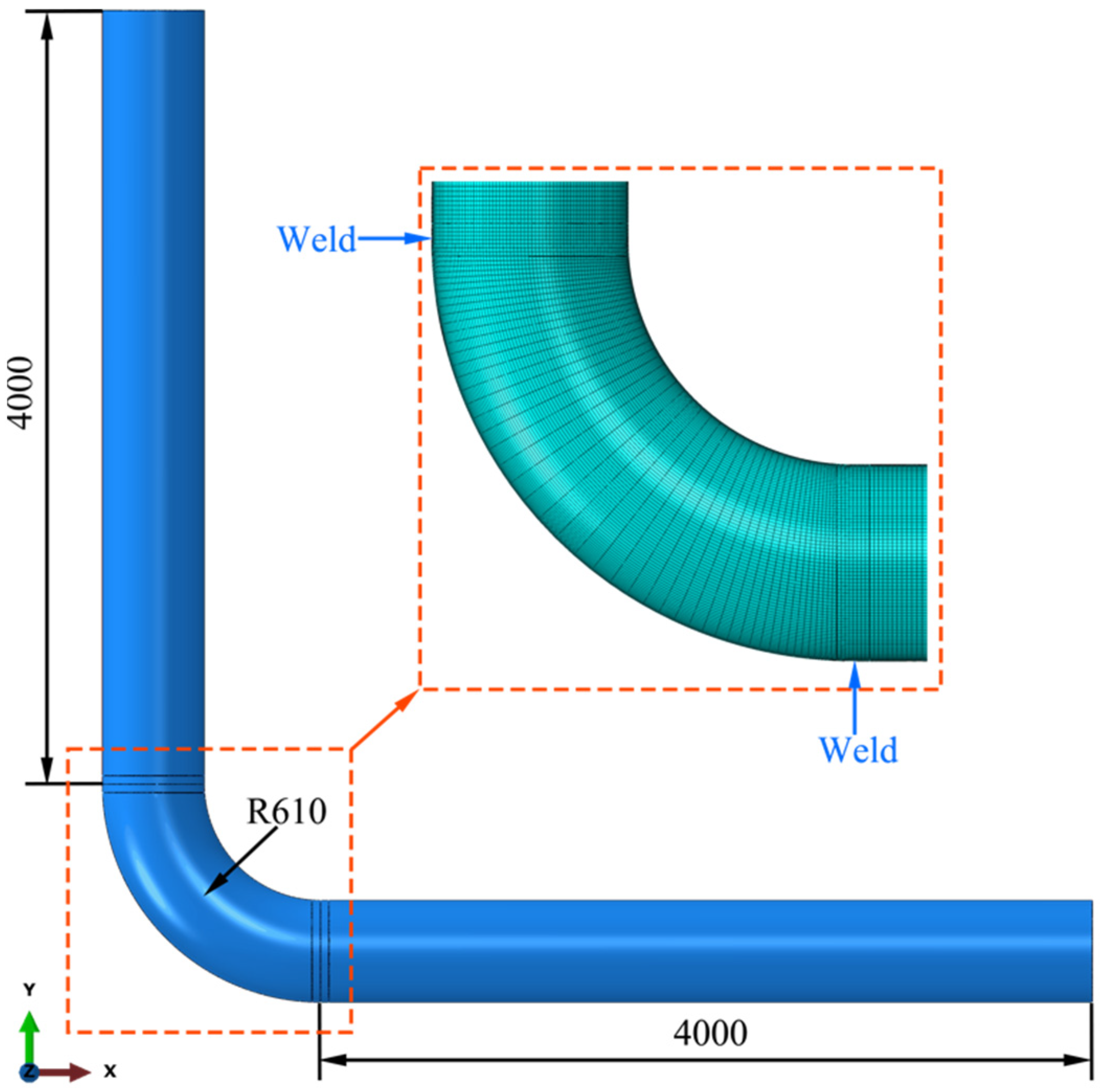
2.2. Finite Element Model

A three-dimensional finite element model is developed to simulate the effect of structural induced stress on creep. The simulation model and FE mesh are shown in Figure 2.
The weld groove angle is 22°, and the widths of the coarse grain heat affected zone (CGHAZ) and FGHAZ are both 1 mm. Fine mesh is used in the HAZ, and a relatively coarse mesh is adopted in the adjacent base metal to balance the simulation accuracy and efficiency. The element type is C3D8R and the element size in the HAZ is 0.25 mm × 8 mm × 8 mm.
One end of the pipe to elbow weld is fixed, and the other end is subjected to axial tension/compression to investigate the effect of structural induced stress on creep. The Norton law [20] is adopted in the FE simulation of creep, given in the multi-axial form by
ε ¯ ˙ c r = 3 2 A σ s n 1 S i j
where ε ¯ ˙ c r is the equivalent creep strain rate, σ s is the equivalent stress, S i j is the stress and n and A are material constants. The material properties of different regions of the P92 steel weld joint are taken from Ref. [21]. The commercial finite element software package Abaqus is used to simulate the creep evolution of the weld.

3. Results and Discussion

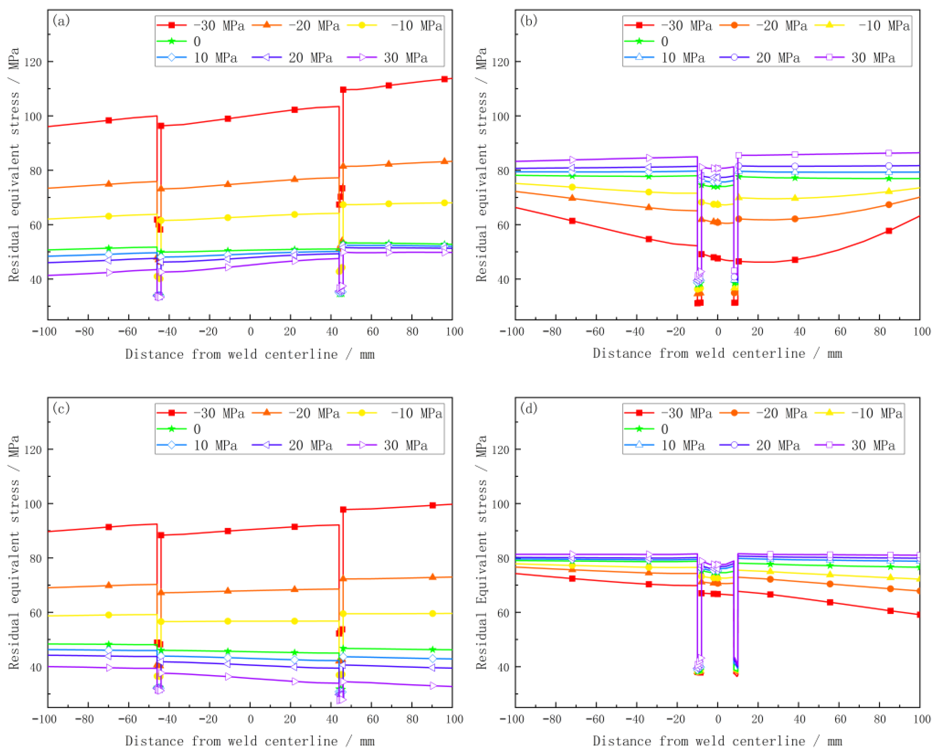
3.1. Effect of Structural Stress on Creep Stress

One end of the pipe to elbow weld is fixed, and σ = −30, −20, …, 30 MPa axial stresses are applied to the other side. The stress distribution of the pipe to elbow weld after creep for 5000 h is shown in Figure 3.
It can be seen from Figure 3 that the internal pressure tends to straighten the elbow, which results in tensile stress on the inner side of the elbow and compressive stress on the outer side of the elbow. The hoop stress near the 12:00 and 6:00 positions on the weld metal (WM) is larger than at the 3:00 and 9:00 positions on the WM. In contrast, the radial and axial stresses are almost identical in different circumferential positions of the WM. Stress on the pipe’s inner wall and its vicinity are significantly higher than on the outer wall. The structural induced stress has little effect on the axial stress of the joint, except for in the FGHAZ. The axial stresses in the FGHAZ of the three simulated cases are about −22.6, −17.3 and −10.9 MPa, respectively. The axial structural induced stress decreases the tensile hoop stress in the WM and adjacent base metal (BM) near the outer wall of the pipe but increases the tensile hoop stress in the WM and adjacent BM near the inner wall of the pipe. The radial stress in the FGHAZ on the pipe’s outer wall is about 14.5 MPa, 26.3 MPa and 35.0 MPa in the three simulated cases; at the inner wall of the pipe FGHAZ, the radial stress is about 18.7 MPa, 26.2 MPa, and 37.2 MPa, respectively. Both axial tensile stress and compressive stress can significantly increase the tensile hoop stress in the FGHAZ near the inner and outer walls of the pipe. The reason may be that the creep strength in the FGHAZ is relatively low; thus, the circumferential deformation caused by axial structural induced stress is mainly concentrated at the FGHAZ, which leads to the significant increase of circumferential stress at this position [22,23]. The expansion of the pipe caused by axial compressive stress will lead to the overall inward bending deformation of the pipe, which will reduce the tensile hoop stress on the pipe’s outer wall and increase the tensile hoop stress on the inner wall [24,25]. Under axial tension, the pipe uniformly shrinks inward, and the bending effect is relatively small. Therefore, the hoop stress in the pipe is almost constant. In the axial direction, the axial stress at different positions of the pipe joint is nearly the same and is approximately equivalent to the axial structural induced stress.

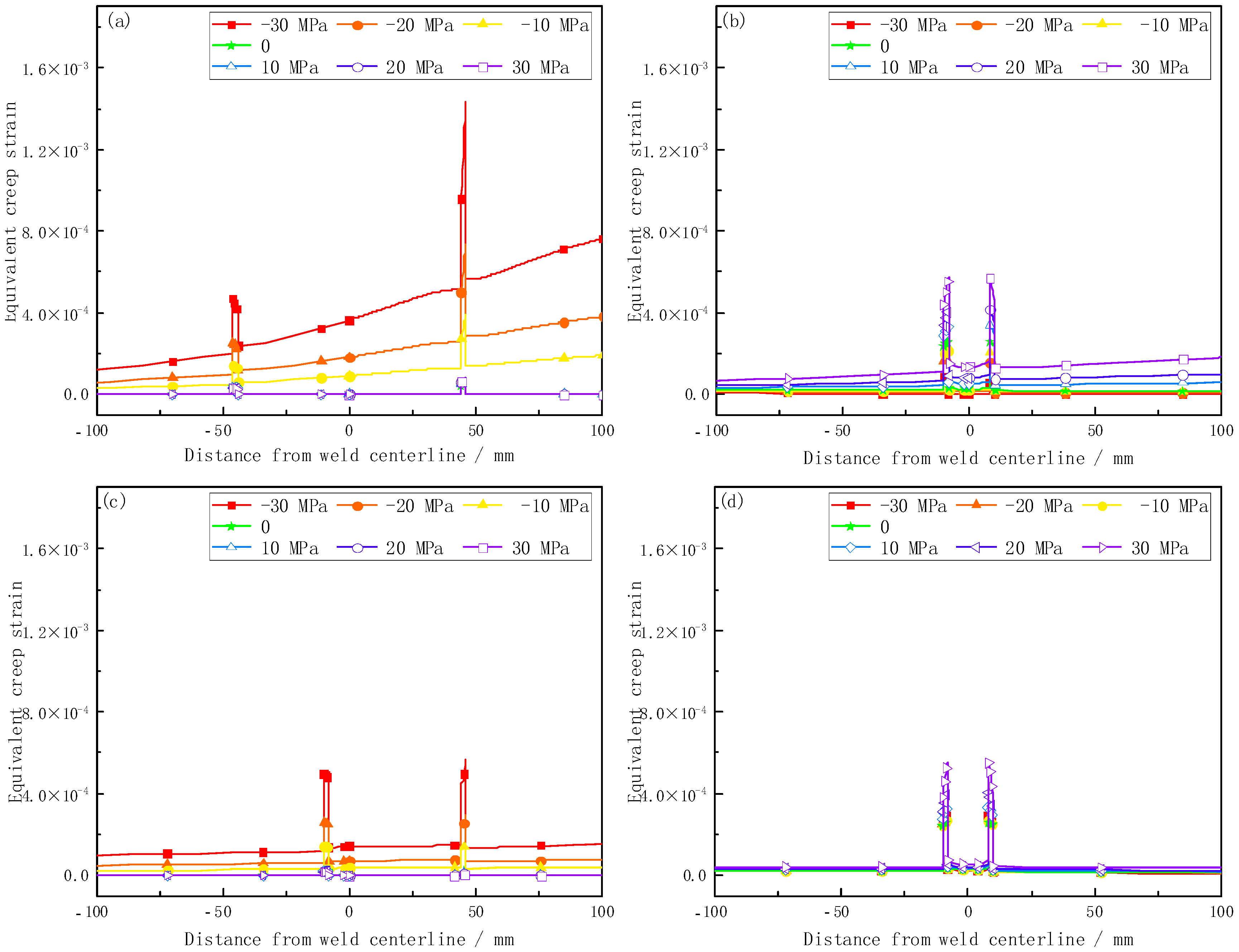
3.2. Effect of Structural Induced Stress on Creep of Pipe Inner and Outer Walls

Figure 4 shows the effect of structural induced stress on the equivalent stress on pipe interior and exterior surfaces. Due to the symmetry, only the stress around the weld of the horizontal pipe is investigated.
It can be seen from Figure 4 that the equivalent stress in the FGHAZ is obviously lower than in the WM and adjacent BM due to their lower creep strength. There is a clear difference in the influence of axial structural induced stress on equivalent stress between the pipe’s interior and exterior surfaces. In the case of free deformation, the equivalent stresses in the FGHAZ at the 12:00 position of exterior and interior surfaces are about 34.0 MPa and 38.0 MPa, respectively. The equivalent stresses in the FGHAZ at the 6:00 position of exterior and interior surfaces are about 32.4 MPa and 38.3 MPa, respectively. In the case of 30 MPa tensile axial structural induced stress, the equivalent stress reduces by about 1.2% to 33.6 MPa in the FGHAZ at 12:00 on the outside surface and increases by about 7.9% to 41.0 MPa in the FGHAZ at 12:00 on the inside surface. The equivalent stress reduces by about 2.5% to 31.6 MPa in the FGHAZ at 6:00 on the outside surface and increases about 6.3% to 40.7 MPa in the FGHAZ at 6:00 on the inside surface. By contrast, when subject to a compressive axial structural induced stress under −30 MPa, the equivalent stress in the FGHAZ at both 12:00 and 6:00 on the outside surface increases by about 82.1% and 50.9% to 61.9 MPa and 48.9 MPa, respectively. The equivalent stress in the FGHAZ at both 12:00 and 6:00 on the inside surface reduces by about 18.2% and 0.3% to 31.1 MPa and 37.9 MPa, respectively. Therefore, it can be concluded that the compressive structural induced stress increases the equivalent stress on the pipe’s outer surface and reduces the equivalent stress on the inner surface, while the tensile structural induced stress has the opposite influence on the equivalent stress of pipe to elbow welds. Moreover, the effect of compressive structural stress is much higher than that of tensile structural stress. The influence of axial structural induced stress on the equivalent creep strain of pipe to elbow welds is shown in Figure 5.
From Figure 5, the equivalent creep strain on the pipe’s outer surface is clearly increased by the compressive axial structural induced stress, while little effect is found on the pipe’s inner surface. By contrast, tensile axial structural induced stress significantly increases the creep strain on the pipe’s inner surface, but the influence on the outer surface is relatively small. In the case of free deformation, the equivalent creep strains in the FGHAZ at the 12:00 position of the inner and outer surfaces are about 3.4 × 10⁻⁵ and 2.4 × 10⁻⁴, respectively; the equivalent creep strains in the FGHAZ at the 6:00 position of the inner and outer surfaces are about 2.2 × 10⁻⁵ and 3.8 × 10⁻⁴, respectively. In the case of a 30 MPa tensile axial structural induced stress, the equivalent creep strain reduces by about 17.7% to 2.5 × 10⁻⁵ in the FGHAZ at the 12:00 position on the outer surface and increases by about 83.3% to 4.4 × 10⁻⁴ in the FGHAZ at the 12:00 position on the inner surface. The equivalent creep strain reduces by about 27.3% to 1.6 × 10⁻⁵ and about 34.2% to 2.5 × 10⁻⁴ in the FGHAZ at the 6:00 position of the outer and inner surfaces, respectively. By contrast, with a compressive axial structural induced stress under −30 MPa, the equivalent creep strain in the FGHAZ at both the 12:00 and 6:00 positions on the outer surface increases by about 13.7 and 1.2 times to 4.7 × 10⁻⁴ and 4.9 × 10⁻⁴, respectively. The equivalent creep strain in the FGHAZ at the 12:00 and 6:00 positions of the inner surface reduces by about 64.2% and 36.8% to 8.6 × 10⁻⁵ and 2.4 × 10⁻⁴, respectively. According to simulation results, it can be concluded that compressive axial structural induced stress can significantly increase the creep strain near the pipe’s outer surface, while at the same time, the creep strain near the pipe’s inner surface is decreased to some extent. The creep strain near the inner surface is clearly accelerated by tensile axial structural induced stress; meanwhile, the creep strain near the pipe’s outer surface is somewhat mitigated.

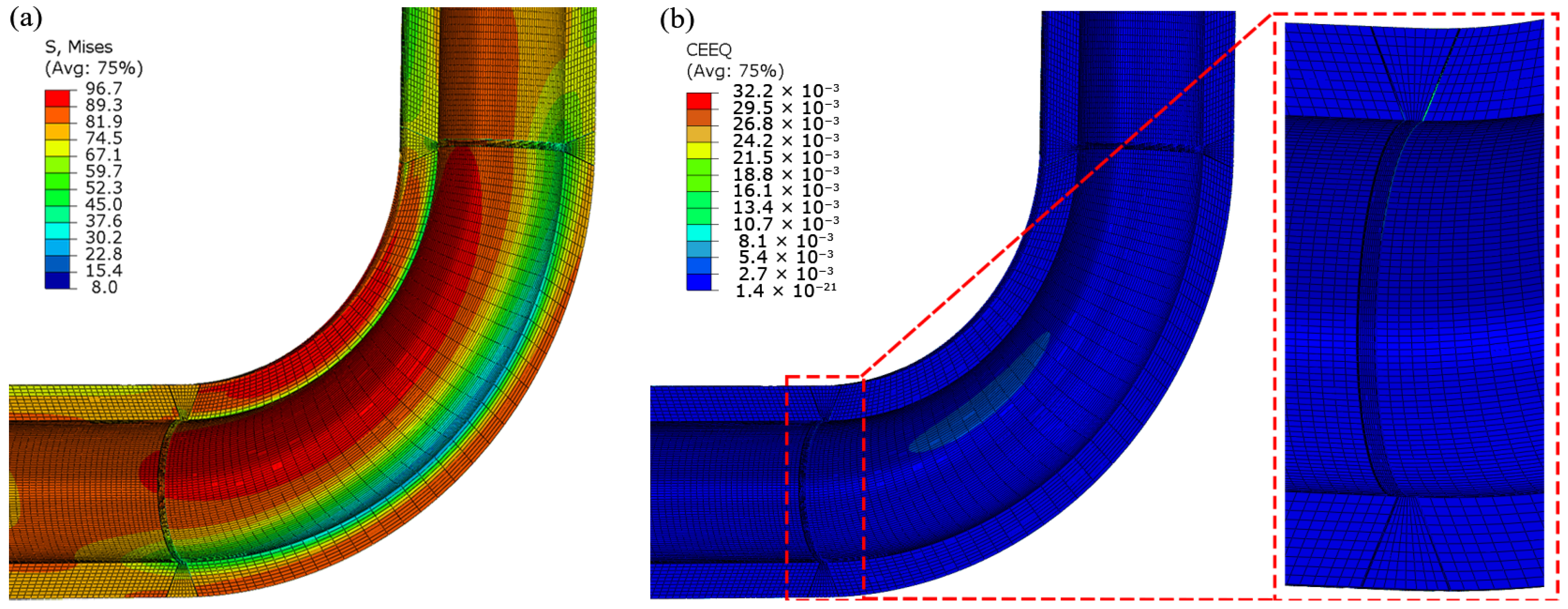
4. Creep of a Pipe to Elbow Joint in an Ultra-Supercritical Boiler

To further illustrate the effect of structural stress on the creep of pipe to elbow welds, the creep of a pipe to elbow joint in the pipeline system of a typical ultra-supercritical boiler was simulated. The pipe stress in operation was calculated by Caesar II software, and the stress distribution plot as the percentage of allowable stress of P92 steel is shown in Figure 6.
It can be seen from Figure 6 that the maximum stress is in the 90° elbow near the center of the pipeline system. The displacement in the top end of the pipe to the elbow welded joint is Ux = 303 mm, Uy = 226 mm, Uz = −303 mm, and the displacement in the bottom end of the pipe to the elbow welded joint is Ux = 357 mm, Uy = 274 mm, Uz = −310 mm. Those displacement results are used as boundary conditions to simulate the creep of the pipe to the elbow welded joint. The equivalent stress and equivalent creep strain of the pipe to the elbow welded joint after creep was simulated for 5000 h is shown in Figure 7.
From Figure 7a, the equivalent stress in the weld of the horizontal pipe is clearly higher than in the weld of the vertical pipe. The maximum stress is located at the center of the inner concave surface of the elbow with a magnitude of about 96.7 MPa. A relatively higher stress is present at the elbow side of the weld than at the pipe side, and a clear difference in stress is found at different circumferential locations. The stress in the weld metal and FGHAZ at the 3:00 position is about 85.4 and 45.7 MPa, respectively; by contrast, the stress in the weld metal and FGHAZ at the 6:00 position is only about 41.7 and 33.5 MPa. From Figure 7b, the equivalent creep strain in the weld of the horizontal pipe is higher than in the weld of the vertical pipe; meanwhile, the equivalent creep strain is not uniform around the circumference of the weld. The equivalent creep strain distribution in the FGHAZ of the weld on the horizontal pipe side, and the crack morphology of the weld after being in service for about 20,000 h are shown in Figure 8.
It is clear from Figure 8a that due to the influence of structural induced stress, there is a clear difference in creep strain in different circumferential locations on the pipe. The creep strain in the FGHAZ at the 6:00 and 8:00 positions are nearly identical between the outer and inner surfaces of the weld, while the creep strain on the inner surface is greater than on the outer surface between the 8:00 and 10:00 positions. The creep strain on the inner surface of the pipe is smaller than on the outer surface between the 10:00 and 12:00 positions. The maximum creep strain is 1.9% and located at the 10:30 position in the FGHAZ on the outer surface, which makes it the weakest part of the welded joint. Steam leakage was observed at this pipe to elbow weld after being in service for about 20,000 h. The crack is located at the FGHAZ of the weld on the horizontal pipe side. The crack initiated around the 10:30 position of the outer surface and then propagated to the inner surface, which is in agreement with the simulation results.

5. Conclusions

The effect of structural induced stress arising from internal steam pressure, and the constraint of supports and hangers in the pipeline system of USC boilers on the creep evolution at pipe to elbow welds was investigated via the FE method, and the following conclusions have been drawn.
  • Compressive axial structural induced stress increases the stress on the pipe’s outer surface and reduces the stress on the inner surface, while the tensile structural induced stress has the opposite influence on the stress of pipe to elbow welds. Moreover, the effect of compressive structural induced stress is much higher than that of tensile structural induced stress.
  • Compressive axial structural induced stress can significantly increase the creep strain near the pipe’s outer surface; at the same time, the creep strain near the pipe’s inner surface is decreased to some extent. Conversely, the creep strain near the inner surface is clearly accelerated by tensile axial structural induced stress. Meanwhile, the creep strain near the outer surface is mitigated to a certain degree. Compared with the free deformation condition in the pipe ends, at a compressive axial structural induced stress under −30 MPa, the equivalent creep strain in the FGHAZ at the 12:00 position on outer surface increases about 13.7 times, while, in the case of a 30 MPa tensile axial structural induced stress, the equivalent creep strain increases by about 83.3% in the FGHAZ at the 12:00 position on the interior surface.
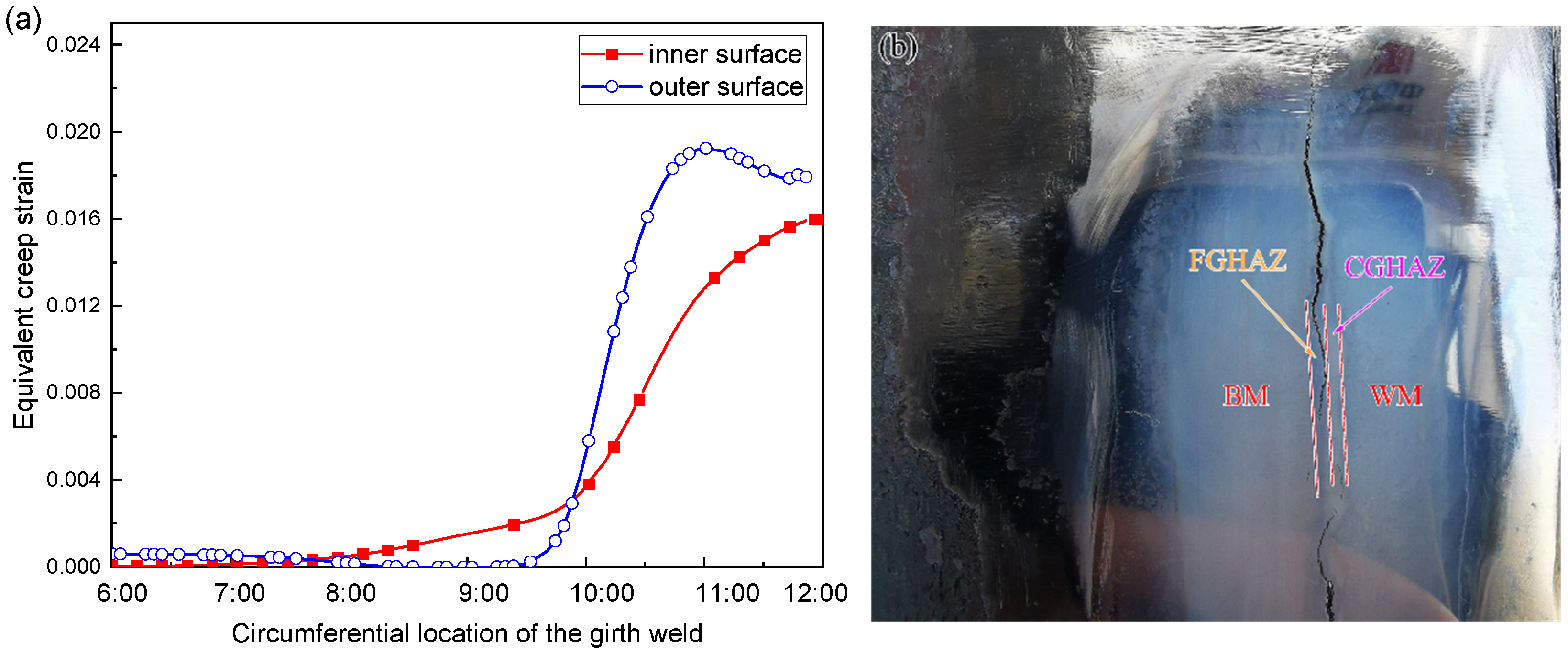
  • A clear difference in creep strain is found in different annular positions of the pipe to elbow weld due to the effect of structural induced stress. The creep strains in the FGHAZ at the 6:00 and 8:00 positions are nearly identical between the outer and inner surfaces of the weld. In contrast, the creep strain on the pipe’s inner surface is more significant than on the outer surface between the 8:00 and 10:00 positions and the creep strain on the pipe’s inner surface is smaller than on outer surface between the 10:00 to 12:00 positions.
  • The maximum creep strain is 1.9% and located at the 10:30 position in the FGHAZ on the pipe’s outer surface, which makes it the weakest part of the welded joint. The location of a crack on a pipe after being in service for 20,000 h is in agreement with the simulation results.

Author Contributions

Conceptualization, Y.L.; methodology, Y.L. and J.Y.; validation, J.Y. and W.W.; writing—original draft preparation, Y.L. and W.W.; writing—review and editing, X.J. and L.H.; project administration, L.H.; funding acquisition, L.H. All authors have read and agreed to the published version of the manuscript.

Funding

This research was funded by the National Natural Science Foundation of China (Grant No. 52105312).

Data Availability Statement

The data presented in this study are available on request from the corresponding author.

Conflicts of Interest

The authors declare no conflict of interest.

References

  1. Li, J.F.; Gu, A.L.; Ma, Z.Y.; Zhang, C.L.; Sun, Z.Q. Economic Development, Energy Demand, and Carbon Emission Prospects of China’s Provinces During the 14th Five-Year Plan Period: Application of CMRCGE Model. Clim. Chang. Res. 2019, 10, 165. [Google Scholar] [CrossRef]
  2. Hao, J.; Gao, F.; Fang, X.; Nong, X.; Zhang, Y.; Hong, F. Multi-factor Decomposition and Multi-scenario Prediction Decoupling Analysis of China’s Carbon Emission Under Dual Carbon Goal. Sci. Total. Environ. 2022, 841, 156788. [Google Scholar] [CrossRef] [PubMed]
  3. Yang, K.; Zhang, Y.; Zhao, J. Elastoplastic Fracture Analysis of the P91 Steel Welded Joint under Repair Welding Thermal Shock Based on XFEM. Metals 2020, 10, 1285. [Google Scholar] [CrossRef]
  4. Tian, X.; Zhang, S.; Xu, H.; Li, T.; Yang, B.; Zhang, M. Assessment of Creep Properties Using Small Punch Test for a 9%Cr-Mo-Co-B Power Plant Steel. Metals 2021, 11, 1996. [Google Scholar] [CrossRef]
  5. Serindağ, H.T.; Tardu, C.; Kirçiçek, İ.Ö.; Çam, G. A Study on Microstructural and Mechanical Properties of Gas Tungsten Arc Welded Thick Cryogenic 9% Ni Alloy Steel Butt Joint. CIRP J. Manuf. Sci. Technol. 2022, 37, 1. [Google Scholar] [CrossRef]
  6. Ezer, M.A.; Çam, G. A Study on Microstructure and Mechanical Performance of Gas Metal Arc Welded AISI 304 L Joints. Mater. Werkst. 2022, 53, 1043. [Google Scholar] [CrossRef]
  7. Çam, G.; Koçak, M.; Santos, J.F. Developments in Laser Welding of Metallic Materials and Characterization of The Joints. Weld. World 1999, 43, 13. [Google Scholar]
  8. Santos, J.F.; Çam, G.; Torster, F.; Insfran, A.; Riekehr, S.; Ventzke, V.; Koçak, M. Properties of Power Beam Welded Steels, Al-and Ti-Alloys: Significance of Strength Mismatch. Weld. World 2000, 44, 42. [Google Scholar]
  9. Çam, G.; Erim, S.; Yeni, Ç.; Koçak, M. Determination of Mechanical and Fracture Properties of Laser Beam Welded Steel Joints. Weld. J. 1999, 78, 193. [Google Scholar]
  10. Adhithan, B.; Pandey, C. Study on Effect of Grain Refinement of P92 Steel Base Plate on Mechanical and Microstructural Features of the Welded Joint. Int. J. Pres. Ves. Pip. 2021, 192, 104426. [Google Scholar] [CrossRef]
  11. Sakthivel, T.; Sasikala, G.; Dash, M.K.; Syamala, R.P. Creep Deformation and Rupture Behavior of P92 Steel Weld Joint Fabricated by NG-TIG Welding Process. J. Mater. Eng. Perform. 2019, 28, 4364. [Google Scholar] [CrossRef]
  12. Xue, W.; Pan, Q.G.; Ren, Y.Y.; Shang, W.; Zeng, H.Q.; Liu, H. Microstructure and Type IV Cracking Behavior of HAZ in P92 Steel Weldment. Mat. Sci. Eng. A-Struct. 2012, 552, 493. [Google Scholar] [CrossRef]
  13. Pandey, C.; Kumar, N.; Sirohi, S.; Rajasekaran, T.; Kumar, S.; Kumar, P. Study on the Effect of the Grain Refinement on Mechanical Properties of the P92 Welded Joint. J. Mater. Eng. Perform. 2022, 31, 4385. [Google Scholar] [CrossRef]
  14. Zhang, W.; Wang, X.; Kang, Z.; Zhang, T.; Jiang, Y.; Zhang, X.; Gong, J. Characterization of the Cyclic Softening and Remaining Creep Behaviour of P92 Steel Weldment. J. Mater. Res. Technol. 2021, 15, 1446. [Google Scholar] [CrossRef]
  15. Meng, Q.; Wang, Z. Creep Damage Models and Their Applications for Crack Growth Analysis in Pipes: A Review. Eng. Fract. Mech. 2019, 205, 547. [Google Scholar] [CrossRef]
  16. Ennis, P.J.; Zielinska-Lipiec, A.; Wachter, O.; Czyrska-Filemonowicz, A. Microstructural Stability and Creep Rupture Strength of The Martensitic Steel P92 for Advanced Power Plant. Acta Mater. 1997, 45, 4901. [Google Scholar] [CrossRef]
  17. Xu, L.; Wen, J.F.; Tu, S.D. Numerical Simulations of Creep Damage and Crack Growth in P92 Steel Welded Joints. Trans. China Weld. Inst. 2019, 40, 80. [Google Scholar]
  18. Zhao, L.; Jing, H.; Xu, L.Y.; An, J.; Xiao, G. Numerical Investigation of Factors Affecting Creep Damage Accumulation in ASME P92 Steel Welded Joint. Mater. Des. 2012, 34, 566. [Google Scholar] [CrossRef]
  19. Chang, Y.; Xu, H.; Ni, Y.; Lan, X.; Li, H. The Effect of Multiaxial Stress State on Creep Behavior and Fracture Mechanism of P92 Steel. Mat. Sci. Eng. A-Struct. 2015, 636, 70. [Google Scholar] [CrossRef]
  20. El-Desoky, O.E.; Abd El-Azim, M.E.; EIKossy, M.R. Analysis of Creep Behavior of Welded Joints of P91 Steel at 600 °C. Int. J. Pres. Ves. Pip. 2019, 171, 145. [Google Scholar] [CrossRef]
  21. Zhao, L.; Jing, H.Y.; Xu, L.Y.; Han, Y.; Xiu, J.; Qiao, Y. Evaluating Creep Property of Distinct Zones in P92 Steel Welded Joint by Small Punch Creep Test. Mater. Des. 2013, 47, 677. [Google Scholar] [CrossRef]
  22. Kimura, K.; Sawada, K.; Kushima, H.; Kubo, K. Effect of Stress on The Creep Deformation of ASME Grade P92/T92 Steels. Int. J. Mat. Res. 2008, 99, 395. [Google Scholar] [CrossRef]
  23. Wang, X.; Pan, Q.G.; Liu, Z.J.; Liu, Z.J.; Zeng, H.Q.; Tao, Y.S. Creep Rupture Behaviour of P92 Steel Weldment. Eng. Fail. Anal. 2011, 18, 186. [Google Scholar]
  24. Wang, X.; Hu, L.; Xu, Q.; Chen, D.X.; Sun, S.T. Influence of Martensitic Transformation on Welding Residual Stress in Plates and Pipes. Sci. Technol. Weld. Join. 2017, 22, 505. [Google Scholar] [CrossRef]
  25. Radaj, D. Heat Effects of Welding: Temperature Field, Residual Stress, Distortion; Springer: New York, NY, USA, 2012. [Google Scholar]
Figure 1. Schematic of the main steam pipeline system of an ultra-supercritical boiler.
Metals 12 01792 g001
Figure 2. Simulation model and FE mesh (unit: mm).
Metals 12 01792 g002
Figure 3. Stress distribution after creep for 5000 h under various axial structural induced stress.
Metals 12 01792 g003
Figure 4. Effect of axial structural induced stress on equivalent stress of pipe to elbow welds: (a) 12:00 outside surface, (b) 12:00 position inside surface, (c) 6:00 outside surface, (d) 6:00 position inside surface.
Metals 12 01792 g004
Figure 5. Effect of axial structural induced stress on equivalent creep strain of pipe to elbow welds: (a) 12:00 position of outer surface, (b) 12:00 position of inner surface, (c) 6:00 position of outer surface, (d) 6:00 position of inner surface.
Metals 12 01792 g005
Figure 6. Stress distribution of the main steam pipeline system in operation.
Metals 12 01792 g006
Figure 7. Equivalent stress (a) and equivalent creep strain (b) of pipe to elbow welded joint after creep proceeded for 5000 h.
Metals 12 01792 g007
Figure 8. Equivalent creep strain distribution in the FGHAZ of the weld on the horizontal pipe side (a) and crack morphology of the weld after being in service for about 20,000 h (b).
Metals 12 01792 g008
Publisher’s Note: MDPI stays neutral with regard to jurisdictional claims in published maps and institutional affiliations.

