Article

Study of Microstructure and Properties of Aluminum/Steel Inertia Radial Friction Welding

Southwest Technology and Engineering Research Institute, Chongqing 400039, China
*
Author to whom correspondence should be addressed.
Metals 2022, 12(12), 2023; https://doi.org/10.3390/met12122023
Submission received: 31 October 2022 / Revised: 21 November 2022 / Accepted: 22 November 2022 / Published: 25 November 2022
(This article belongs to the Special Issue Welding and Joining of Dissimilar Materials)

Abstract

:
In this paper, 6061-T6 aluminum alloy and 30CrMnSiA steel are bonded by inertia radial friction welding (IRFW). The formation mechanism of the aluminum/steel friction welded joints and the effect of the welding parameters on the mechanical properties are investigated through the microstructure, microzone composition, and mechanical property analysis. The results show that no visible intermetallic compound layers (IMCs) are detected on the aluminum/steel welding interface, which may be due to Si element aggregating in the welding interface and then forming a Al−Fe−Si phase, preventing the formation and growth of an Al−Fe IMCs. Eventually, a micron ultrathin interface reaction layer composed of Al0.7Fe3Si0.3, FeAl, and Fe3Al phases is formed at the aluminum/steel welding interface. The maximum average shear strength of the joint is 176 MPa. The shear fracture is a typical ductile fracture. Properly reducing the friction speed and increasing the upsetting pressure can improve the bonding strength of aluminum/steel joints.

1. Introduction

Lightweight represents one of the main directions of research for various industries in the realization of “Carbon Neutrality and Emission Peak”. Steel metal components are gradually being replaced by lightweight alloys such as aluminum alloys, magnesium alloys, and titanium alloys. Aluminum alloys, for example, are a structurally lightweight alternative with high specific strength, mature machining process, and low manufacturing cost. As aluminum alloys alone can hardly meet the strength requirements for large loads, high frequency vibrations and other working conditions, developing aluminum/steel composite components has become an inevitable choice. However, given the difficulty of welding two physically different materials together, the high strength bonding of aluminum/steel composite components is a great challenge for its engineering applications.
Research has shown that the thick intermetallic compound layers (IMCs) generated at the aluminum/steel welding interface are an important contributor to reducing joint strength [1,2]. IMCs comprise intermetallic compounds such as Fe3Al, FeAl, FeAl2, and Fe2Al5. With a reduction in the IMCs thickness, the aluminum/steel joint strength increases rapidly [3,4]. Controlling the welding heat plays a significant role in the generation of IMCs. Friction welding as a solid-phase welding process stands out from the other dissimilar metal welding processes due to its low heat input, density, uniform and fine joint texture, and effective control of IMCs thickness [5,6]. Ma et al. [7] discovered a submicron IMCs at a 2A14 aluminum alloy/304 stainless steel inertia friction welded joint. Qin et al. [8] observed a 0.4–0.7μm IMCs at the 1/2 radius of a 7075 aluminum alloy/37CrMnMo steel inertia friction welded interface, but saw no obvious IMCs in the center and at the edge. Kimura et al. [9] bonded A6063 aluminum alloy with 304 stainless steel by inertia friction welding and yielded an aluminum/steel joint with IMCs thickness of only 25 nm. Wan et al. [10] bonded AA6061 aluminum alloy with AISI 316 steel by inertia friction welding and yielded an aluminum/steel joint IMCs thickness of 0.3μm, and a joint tensile strength of 166 MPa. The above scholars have done a vast amount of research on aluminum/steel axial friction welding, and have obtained high-quality aluminum/steel friction welding joints with good structure and performance. However, there are few research results on aluminum/steel radial friction welding. The evolution mechanism of the welding interface microstructure is not clear, and neither is the link between welding parameters and properties. In this study, 6061-T6 aluminum and 30CrMnSiA steel are bonded by inertia radial friction welding (IRFW). The formation mechanism of the aluminum/steel friction welded joint and the effect of the welding parameters on the mechanical properties are investigated. Our aim is to provide theoretical support for the development and application of aluminum/steel inertia radial friction welded composite components.

2. Materials and Methods

Hot−rolled annealed 30CrMnSiA steel produced by Daye Special Steel Co., Ltd. (Huangshi, China) and 6061-T6 aluminum alloy produced by Southwest Aluminum Co., Ltd. (Kunshan, China) were used for the experiments. We have referred to GJB 1951A-2020 and GB/T 3190-2020, respectively, for the chemical composition of the two materials (Table 1).
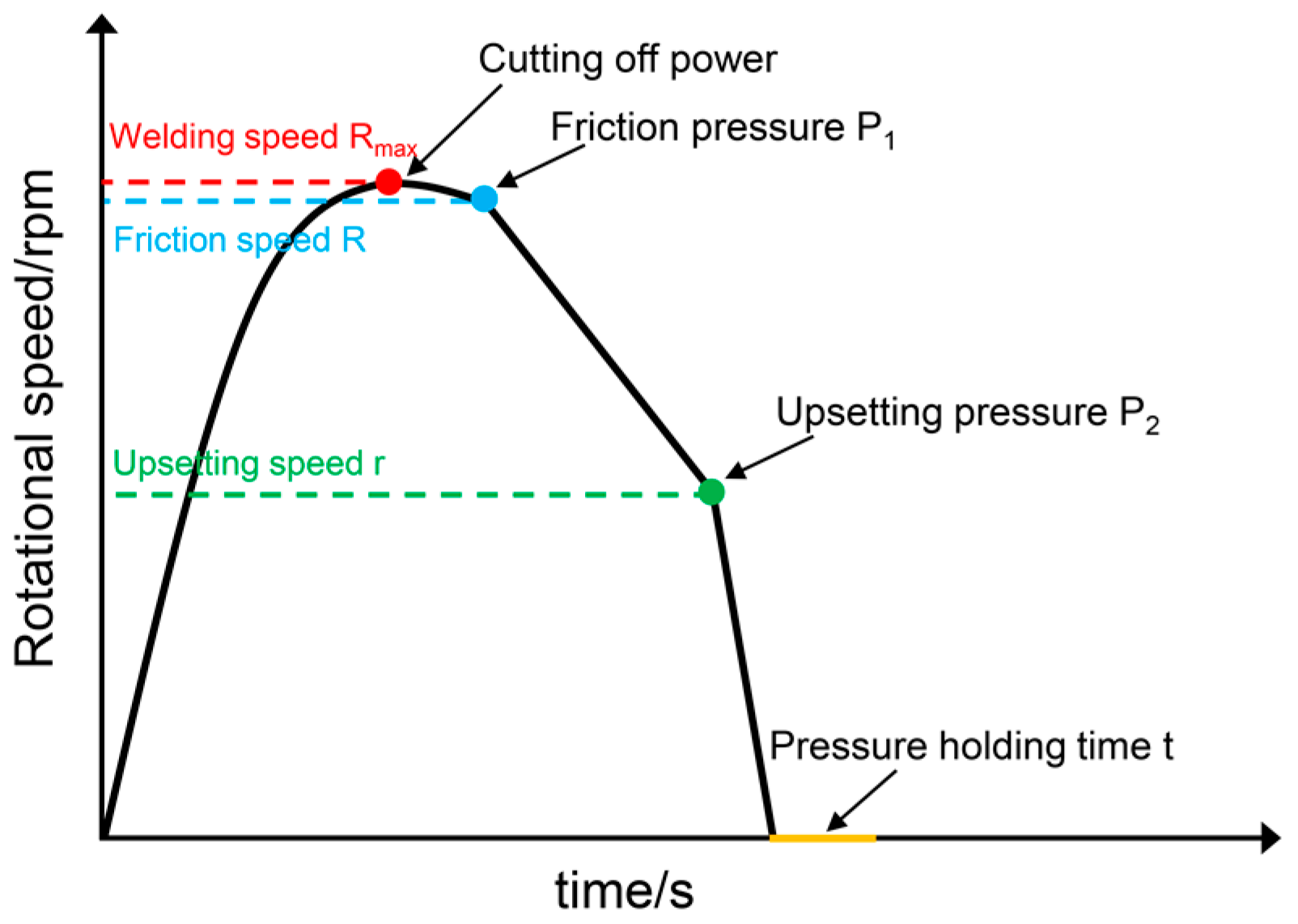
The two materials were bonded by IRFW, and the weldment structure and size are shown in Figure 1. The aluminum alloy weldment size was Φ45 mm × 9 mm × 5 mm (diameter × wall thickness × width), and the steel was Φ26 mm × 60 mm (diameter × length). We used an inertia radial friction welding machine with maximum radial pressure of 30T developed by ourselves, and the variation in the welding process parameters is shown in Figure 2. Figure 3 shows the welding process. P is the radial force exerted on the aluminum alloy ring, F1 and F2 are the axial force and radial force exerted on the steel rod, respectively, which are pressurized by the welding tooling under the action of the hydraulic oil cylinder of the welder, and the pressure can be accurately controlled by the welding procedure of the welder. The aluminum/steel IRFW process was as follows: Firstly, the aluminum alloy ring and steel rod were clamped at the corresponding position of the welding machine through the tool to prevent their movement before welding from affecting the welding quality; after that, driven by cylinder pressure, the steel rod and the flywheel reached welding speed Rmax, then the power was cut off, the steel rod continued to rotate under the inertia force of the flywheel, and fell to the friction speed, R. At the same time, the cylinder exerted radial pressure (friction pressure, P1) on the aluminum alloy ring to induce friction with the steel surface and undergo plastic deformation, and then the steel rod rotation speed was reduced to the upsetting speed, r. The cylinder then applied greater radial pressure (upsetting pressure, P2) to the aluminum alloy ring until the steel rod stopped rotating. After holding the pressure for a certain time t, the aluminum and steel surface was fully in contact, and the metallurgical combination occurred to form a weld. Previous research experience showed that the maximum welding speed and welding pressure were the key process parameters that affect the welding heat input and have a direct impact on the welding quality. Therefore, this paper carried out aluminum/steel IRFW tests under different friction speed, R, friction pressure, P1, and upsetting pressure, P2, to explore the influence of the welding parameters on the microstructure and properties of aluminum/steel IRFW joint (Table 2). Other welding parameters were set as: Rmax = (R + 50) rpm, upsetting speed r = 800 rpm, and pressure holding time t = 5 s.
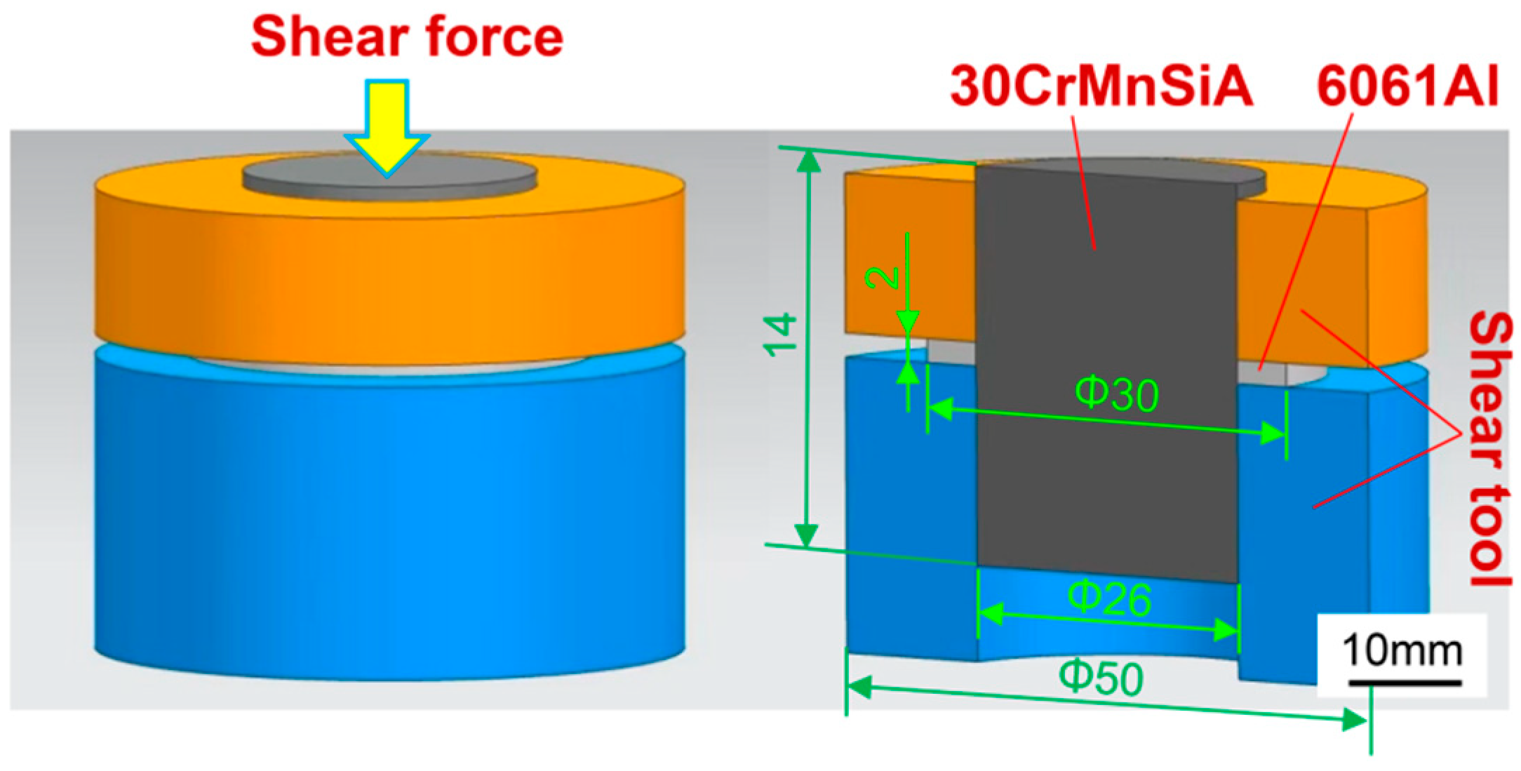
To observe the micromorphology and microstructure of aluminum/steel welded joint, a joint metallographic sample was cut off the welded sample (Figure 4A), coarsely ground and then finely ground with SiO2 paper and by mechanical polishing, then, the steel and aluminum of the metallographic sample were corroded by 5% nitric acid alcohol and Keller’s reagent (2.5 mL HNO3 + 1.5 mL HCL + 1 mL HF + 45 mL H2O), respectively. Then, its microstructure was observed under an MPG3 optical microscope (Olympus, Tokyo, Japan). The micromorphology and phase of the aluminum/steel welding interface and shear fracture were analyzed under an FEI Nano 650 (Thermo Fisher Scientific, MA, USA) field emission scan electron microscope (FE-SEM) fitted with an onboard energy spectrum tester, and the accelerating voltage was 15 kV and WD was 10 mm. Since the welded sample is of an overlapping thin-walled ring structure, in order to test the bonding force of the aluminum/steel welded joint, an Instron 5569 universal material testing machine (Instron Corporation, Boston, USA) was used to test the shear strength of the joint. Figure 5 shows the shear test method. The specific test methods are as follows: three welding samples were prepared for each set of welding parameters, and one shear sample was taken from the middle of the joint for each welding sample (Figure 4A). The thickness of the aluminum alloy ring of the shear sample was 2 mm. The shear tooling (Figure 4B) and shear sample was assembled, and then, The ram of the universal material testing machine was used to hold the punch to pressurize the shear sample until the aluminum ring fell off, at an indenter speed of 2 mm/min. The cross-sectional microhardness distribution of the aluminum/steel joint was measured with an HXD-1000TM (Shanghai Wujiu Automation Equipment Co., Ltd., Shanghai, China) microhardness tester, and the microhardness was continuously measured from the steel base metal side to the aluminum base metal side, at the test force of 100 g on the steel side and 50 g on the aluminum side. The distance between the two adjacent points was 50μm.

3. Results

3.1. Macromorphology

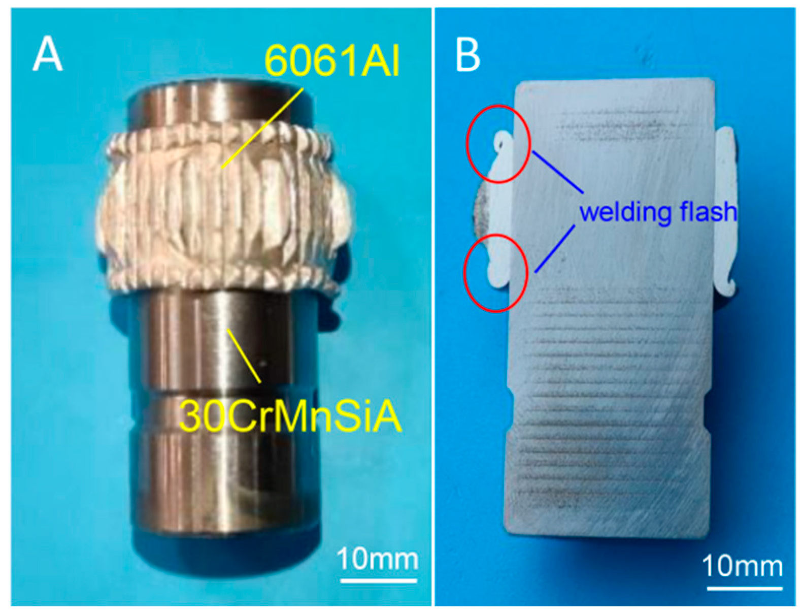
Figure 6 shows the macromorphology of the IRFW joint of sample 5. Under rotary friction and large radial pressure, the aluminum ring is severely plastically deformed both radially and axially. The aluminum ring surface was clamped by the tool and dentate indentation has formed (Figure 6A). Welding flashes with different degrees of crimping along the axial sides are formed (Figure 6B), and the asymmetry of the flashes on both sides maybe caused by the uneven radial pressure. In addition, it can be found that there is no macroscopic plastic deformation on the steel side. In order to inspect the welding condition of welded joints, we first fixed the welding sample in the bench clamp, and then used a chisel to hammer and tear the aluminum/steel joint welding interface along the outer surface of the steel rod to check the unwelded defects. Figure 7 compares the macromorphology of the aluminum/steel IRFW joint under different welding parameters. The results show that the friction speed, friction pressure and upsetting pressure all affect the forming quality of aluminum/steel welding. With the increase in welding parameters, the welding interface is welded on both sides but not in the middle. When the welding energy input is too low, there will be unwelded defects in the middle of the welding interface or even the whole welding surface.

3.2. Microstructure

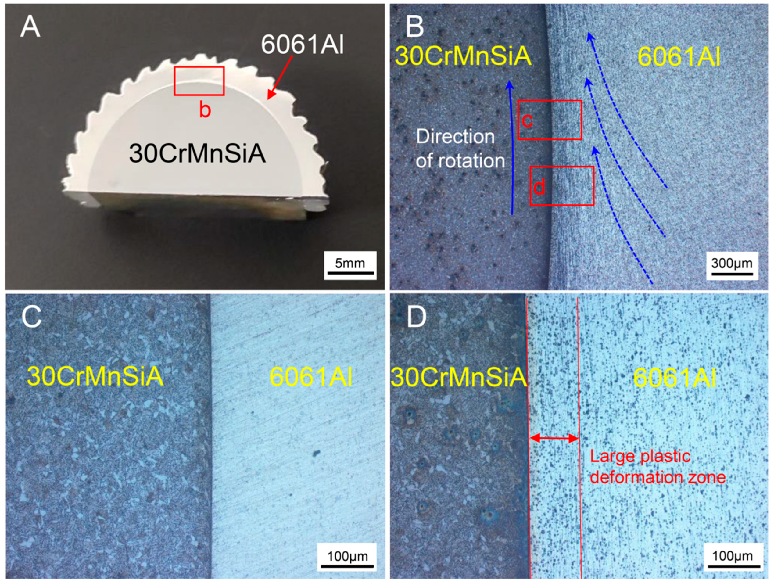
Figure 8 shows the cross-sectional microstructure of the joint of sample 5. Under the combination of rotary friction force and radial pressure, the aluminum-side metal is severely plastically deformed, and a circumferential streamline morphology in line with the steel rod rotation direction (Figure 8B) is observed. The second-phase particles in aluminum are aligned in a circumferential orientation with the material flow. In addition, at the aluminum−side welding interface, the original grains extrude and are deformed; broken to form a large plastic deformation zone, and the density of the second phase particles in this zone is significantly increased (Figure 8D). The steel−side metal is not plastically deformed at the welding interface, and it has effectively retained the original microstructure state, i.e., a ferrite (the bright white area) and pearlite structure (Figure 8C).
Figure 9 shows the micromorphology and energy spectrum results of the aluminum/steel welding interface under different welding parameters. It can be seen from Figure 9A–D that the aluminum/steel welding interface is well defined with no visible IMCs. Inside the aluminum alloy substrate, numerous fine second-phase particles, no more than 3μm in size, are dispersed. EDS point composition analysis shows that this dispersoid is a Al−Fe−Si phase (Figure 9E,F), which is the original dispersion strengthening phase of the aluminum alloy matrix. Under the welding parameter conditions of friction speed R = 1600 rpm, friction pressure P1 = 2 MPa, and upsetting pressure P2 = 3 MPa, a strip of unwelded defect with a maximum width of 3.5μm was formed at the aluminum/steel welding interface in a central position (Figure 9A). When the upsetting pressure reached 7 MPa, the aluminum/steel welding interface is good enough that no unwelded defect was identified (Figure 9B). At the constant upsetting pressure of 7 MPa, no cracks, holes, or other unwelded defects appeared on the aluminum/steel joint, neither when the friction pressure was increased or when the friction speed was reduced within a reasonable range (Figure 9C,D).
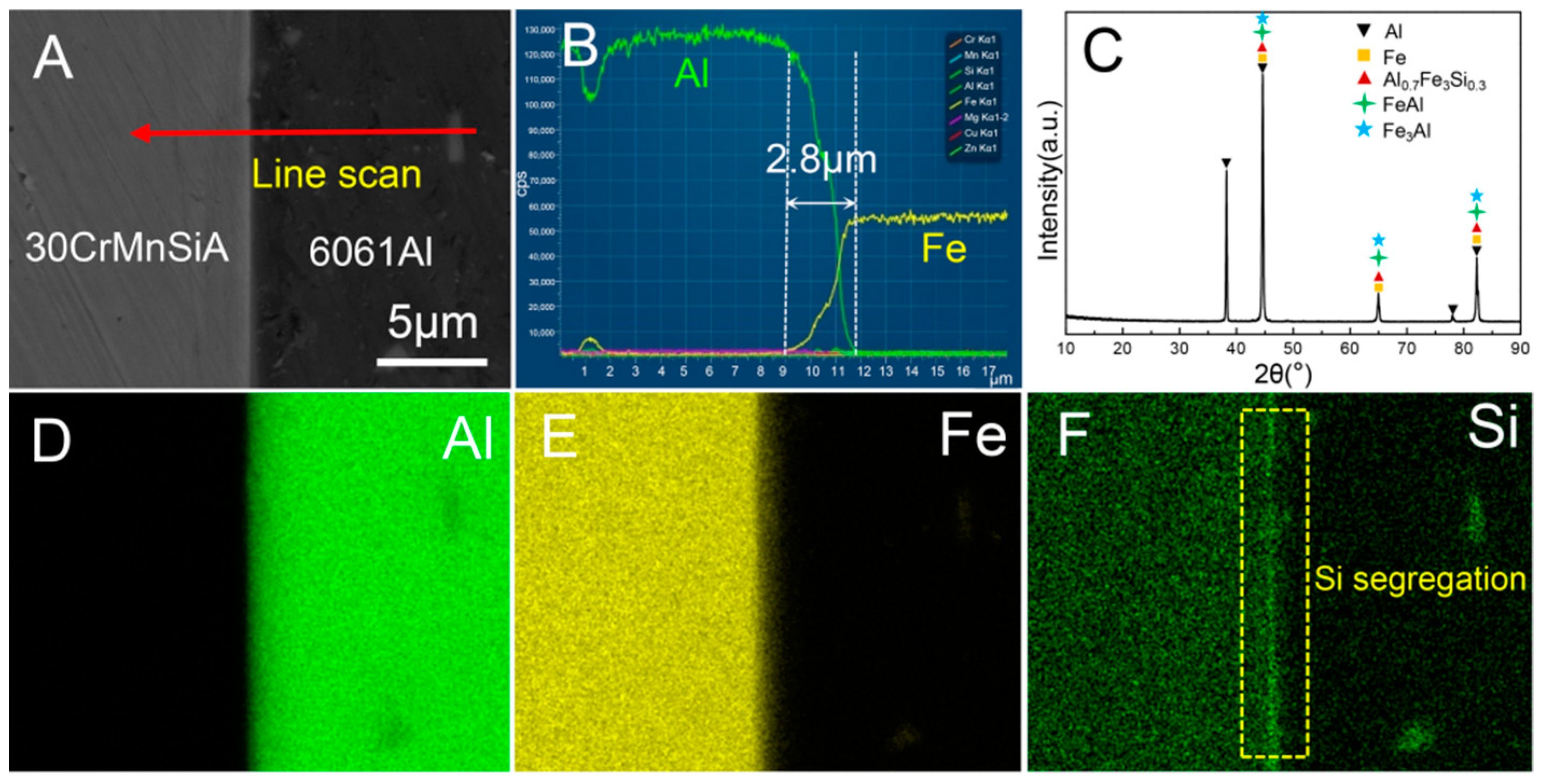
In order to further identify the elemental distribution and phase composition of the aluminum/steel welding interface, area scanning, line scanning, and XRD analysis were carried out on the welding interface of sample 5 (Figure 10). From the line scanning result in Figure 10B, there is an approximately 2.8 μm wide Fe/Al inter-diffusion zone on the welding interface, but there is no element transition platform, and the diffusion of Fe element into the aluminum side is much broader than the diffusion of Al element into the steel side. In addition, in Figure 10F, Si element is obviously aggregated at the aluminum/steel welding interface. XRD results show that the aluminum/steel welding interface is composed of Al0.7Fe3Si0.3, FeAl, and Fe3Al (Figure 10C).

3.3. Shear Strength

Figure 11 compares the average shear strength of the aluminum/steel IRFW joint under different welding parameters. When the welding parameters were friction speed R = 1600 rpm, friction pressure P1 = 2.5 MPa, and upsetting pressure P2 = 7 MPa, the average shear strength of the aluminum/steel IRFW joint reached its maximum of 176 MPa. The measured average shear strength of the 6061-T6 aluminum alloy base metal is 202 MPa, and the strength coefficient of the aluminum/steel IRFW joint is as high as 87.1%. In order to compare the effects of different welding parameters on the shear properties of joints, the strength fluctuation coefficient, α, is introduced in this paper, and the calculation method is shown in Formula (1):
α = (σmax − σmin)/σmin × 100%
Including:
σmax—maximum shear strength
 
σmin—minimum shear strength
 
It can be concluded from the test results that when the friction speed was increased to R = 1500 rpm, the average shear strength of aluminum/steel joint decreased from 173 MPa to 148 MPa due to the increase in friction speed, and the strength fluctuation coefficient was 16.9%. As the friction pressure and upsetting pressure increased, the shear strength of the aluminum/steel joint first increased and then reduced. The minimum average shear strength of the former was 161 MPa, the maximum average shear strength was 176 MPa, and the strength fluctuation coefficient was 9.3%. The minimum average shear strength of the latter was 143 MPa, the maximum average shear strength was 163 MPa, and the strength fluctuation coefficient was 13.9%. According to the changes in the average shear strength of the aluminum/steel joints under the different welding parameters above, friction speed affects joint shear strength more significantly compared to the friction pressure and the upsetting pressure.
Figure 11. Average shear strength of the aluminum/steel joints under different welding parameters: (A) Friction speed; (B) Friction pressure; (C) Upsetting pressure.
Metals 12 02023 g011

3.4. Fracture Morphology

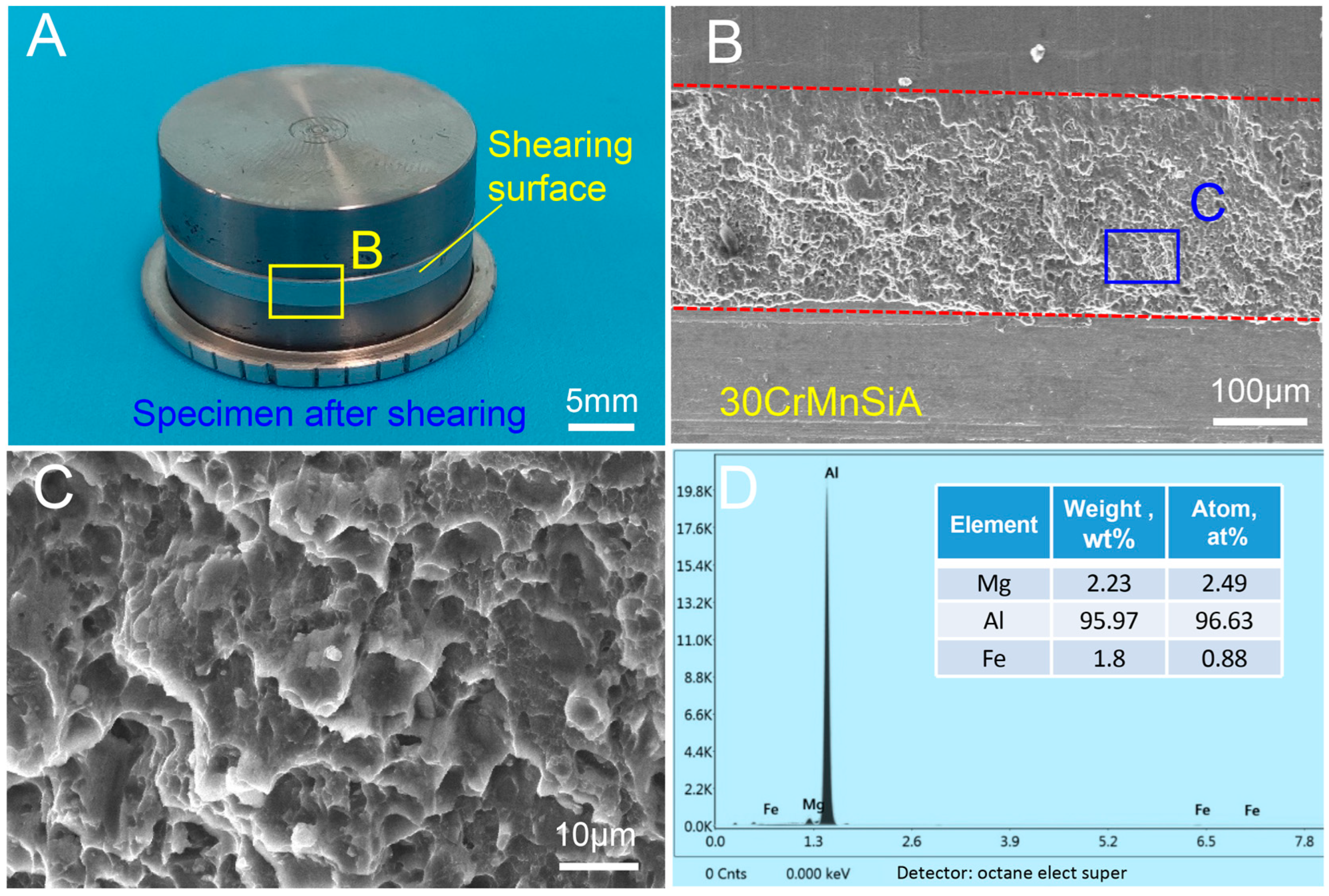
The microstructure and chemical composition of the aluminum/steel joint shear fracture of sample 5 was analyzed and as shown in Figure 12. Figure 12B shows that the steel-side metal is uneven within the shear surface. Enlargement of local points reveals that the shear fracture consists of numerous dimples and tear edges. They are all typical ductile fractures (Figure 12C). EDS area scanning of the area in Figure 12C shows that this area is primarily composed of Al, Mg, and Fe with relative mass fraction of 95.97%, 2.23%, and 1.8%, respectively (Figure 12D). This suggests that after friction welding, aluminum/steel dissimilar metals have been fully metallurgically bonded. Under the shear force, the aluminum alloy base metal is torn, leaving a large amount of aluminum alloy base metal stuck to the welding surface of steel.

3.5. Microhardness

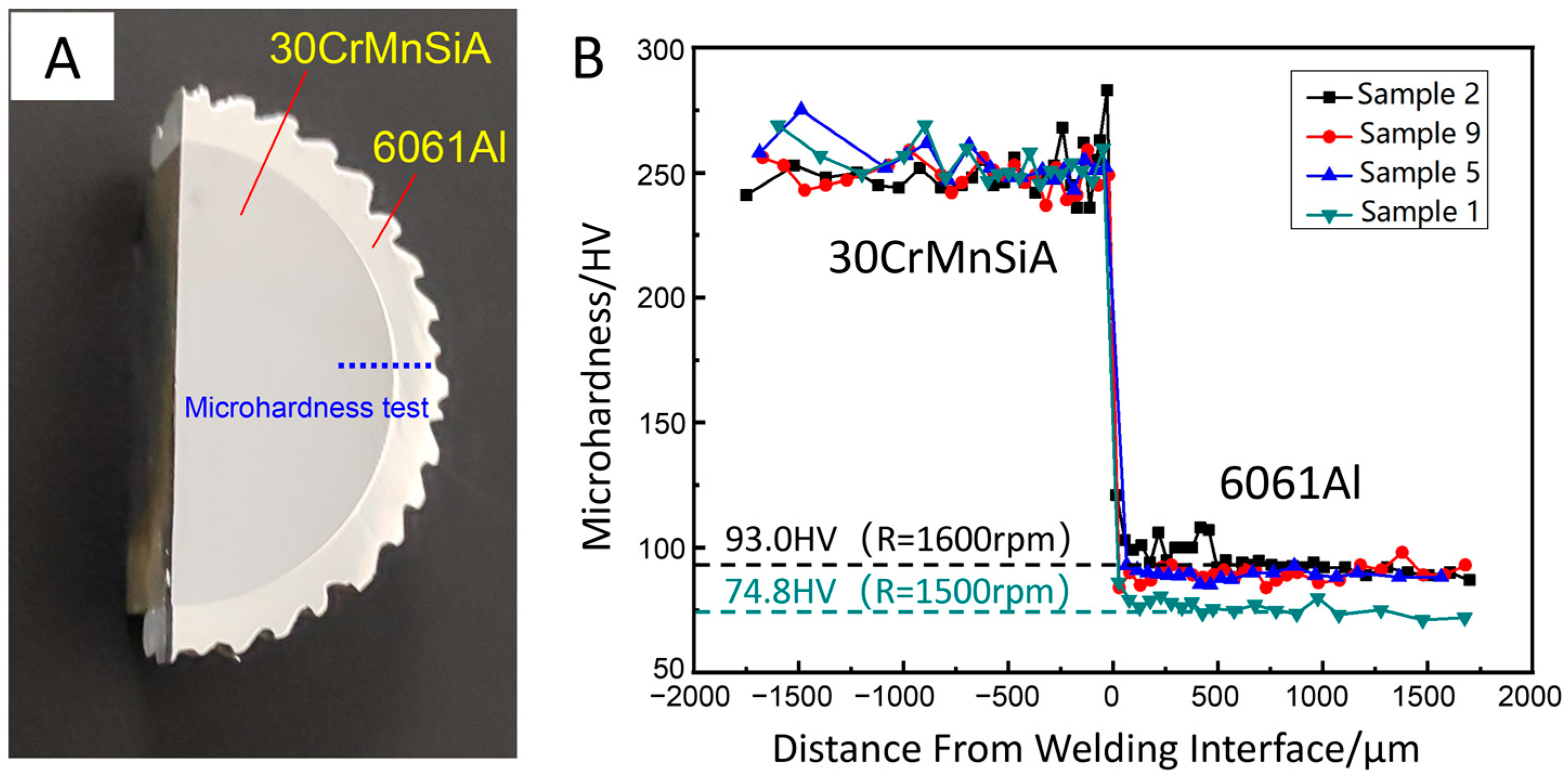
Continuous microhardness tests were performed on both sides of the aluminum/steel joint. Figure 13A shows the position of the microhardness, teats, and the distance between the testing points is 50μm. Figure 13B shows the microhardness distribution of the aluminum/steel joint under different welding parameters. It can be seen from Figure 13B that the steel side is far harder than the aluminum side, and the microhardness profile is also quite flat. Additionally, the steel-side microhardness does not change prominently under different parameters from about 250 HV. The aluminum-side microhardness profile is also quite flat, but the microhardness value differs under different parameters. Welding pressure does not affect the microhardness of the aluminum substrate significantly, but the microhardness of the aluminum substrate differs remarkably under different friction speeds. When the welding parameters are set as friction speed R = 1500 rpm, friction pressure P1 = 2 MPa, and upsetting pressure P2 = 7 MPa, the average aluminum-side microhardness is 74.8 HV. When the friction speed, R, increases to 1600 rpm, the aluminum-side average microhardness is 90.3 HV, which is 24%higher. Compared to the welding pressure, friction speed affects the aluminum/steel joint hardness more significantly.

4. Discussion

Aluminum and steel have great differences in strength, melting point and other physical properties, so different structural state transitions usually occur under the thermal−mechanical coupling of friction welding. IRFW is a solid−state technology, its welding peak temperature is always below the melting point of aluminum alloy [11]. Therefore, aluminum−side metal is thermoplastic and undergoes plastic flow, grain deformation, crushing, and dynamic recrystallization, while the steel-side metal has almost no change in microstructure under short-term low temperature conditions (Figure 8). Due to the influence of welding parameters, different welding energy inputs lead to a difference in aluminum/steel interface metallurgical bonding. As can be seen in Figure 7, with the increase in friction speed, friction pressure and upsetting pressure, more thermoplastic aluminum alloys are extruded along the axial sides and then a flash formed. However, the fresh aluminum metals with low temperature in the central area are not sufficiently bonded with the steel, resulting in the both the sides being welll−welded, but the middle being unwelded. However, low welding energy input also leads to unwelded defects in the aluminum/steel joints, which is related to insufficient diffusion of the metal elements on both sides of the interface at low temperature and failure to achieve metallurgical bonding [12]. Figure 9 shows that appropriately increasing the upsetting pressure can effectively avoid unwelded defects. Some studies have shown that increasing the upsetting pressure is beneficial in promoting the plastic deformation of the aluminum alloy at high temperature, resulting in a large number of crystal defects such as grain boundaries, dislocations and vacancies, which provide a driving force for the formation of new phases and promote the metallurgical bonding of welding interfaces [13,14,15].
Figure 9 shows that no obvious IMCs layer is found at the aluminum/steel welding interface, indicating that the formation of Al−Fe intermetallic compounds is inhibited, which may be largely related to the aggregation of Si element at the welding interface. Some reports have also seen Si element aggregating in Al−Fe IMCs in aluminum/steel laser brazing to form an Al−Fe−Si phase. The presence of Si element retards the diffusion of Fe and Al elements into each other, thus inhibiting the generation of Al−Fe IMCs [16,17]. The Si element aggregate can also be observed at the welding interface in Figure 10F, and XRD has detected that the Si element exists in the form of Al0.7Fe3Si0.3 phase at the interface. In addition, Al−Fe IMCs such as FeAl and Fe3Al are generated, but the IMCs layer at the interface is thin and difficult to find in the microstructure. One of the main reasons for the formation of the ultrathin intermetallic reaction layer at the aluminum/steel interface may be that the aggregation of Si at the welding interface has an inhibitory effect on the growth of Al−Fe IMCs.
The influence of welding parameters on the mechanical properties of the aluminum/steel joint is also closely related to the welding interface metallurgical bonding and the formation of IMCs [18]. Figure 11 shows that compared to the friction pressure and the upsetting pressure, the friction speed affects the aluminum/steel joint shear performance significantly. Friction speed is the main source of welding heat input, and the increase in friction speed increases the energy input in the aluminum/steel friction interface [19], which leads to aluminum alloy ring plastic deformation under high temperature and high radial pressure. Then, element diffusion with steel-side metal occurs, forming the aluminum/steel dissimilar metal bonding surface. However, a high friction speed will lead to a prolonged friction time. Yilmaz et al. [20] found that there was a linear relationship between the thickness of an aluminum/steel inertia friction welded joint’s IMCs layer and the square root of friction time. The extension of friction time would lead to an increase in the thickness of the brittle IMCs layer, which would reduce the mechanical properties of the aluminum/steel joint. Therefore, on the premise of satisfying the full metallurgical combination of aluminum alloy and steel, the friction speed should be reduced appropriately.
The thickness and type of the welding interface’s IMCs make a great difference to the joint’s properties. Their variation is primarily linked to welding heat input, material flow deformation at the interface, and cooling rate [21]. According to the above discussion, the formation process of the aluminum/steel IRFW IMCs layer can be assumed, as shown in Figure 14. Firstly, the aluminum ring and the high-speed rotating steel rod create vigorous friction under friction pressure, P1, and the temperature of the aluminum/steel welding interface rapidly rises to approximate the solidus temperature of the aluminum alloy. The aluminum alloy changes from a solid state to a thermoplastic state, plastic deformation occurs and there is close contact with the steel surface, as shown in Figure 14A. Studies [21] have shown that when the temperature is higher than 400 °C, the Fe atoms begin to diffuse into the aluminum matrix, and when the temperature is above 800 °C, the Al atoms have obvious diffusion behavior into the steel matrix. Therefore, in the low-pressure friction stage, because the welding temperature is much lower than 800 °C, there is almost only a single diffusion of Fe atoms into the aluminum matrix at the welding interface [22]. As the diffusion rate of Fe atoms is very small at this temperature [23], a small amount of the Al−Fe IMCs is formed near the aluminum−side of the welding interface, as shown in Figure 14B. Then, the welding enters the high pressure forging stage, and the thermoplastic aluminum alloy matrix undergoes severe plastic deformation under the high radial pressure. and the aluminum grains at the welding interface are broken, providing a large number of nucleation points. The welding thermal cycle promotes the friction process of dynamic recrystallization. However, due to the short−time friction (about 3 s) of friction welding and the high thermal conductivity of the aluminum alloy, the cooling speed is relatively large, and the grain cannot grow up quickly enough to form the fine crystal zone. This result in a large number of crystal defects such as grain boundaries and dislocations, which provide channels for the diffusion of atoms [15,24]. Moreover, under the superposition of deformation heat and friction heat, the welding interface temperature peaks. The diffusion coefficient of atoms in the substrate on both sides of the interface increases significantly, but at the same time, the Si atoms in the thermoplastic aluminum alloy substrate aggregate in the aluminum/steel welding interface to generate a Al−Fe−Si phase. The presence of Si atoms inhibits the inter-diffusion and compounding between Fe and Al atoms and prevents further growth of the IMCs. Eventually, a micron ultrathin interface reaction layer is formed at the aluminum/steel welding interface, as shown in Figure 14C.

5. Conclusions

(1)
In this work, the optimal welding parameters of 6061-T6 aluminum alloy/30CrMnSiA steel IRFW are for sample 5: friction speed R = 1600 rpm, friction pressure P1 = 2.5 MPa, and upsetting pressure P2 = 7 MPa. The average shear strength of the joint reaches a maximum of 176 MPa, which is 87.1% of the shear strength of the 6061-T6 aluminum alloy base metal, and the shear fraction is a typical ductile fracture; Aluminum/steel joints have good adhesion, and can be used in the surface modification of steel structures, and aluminum/steel rotary lightweight structures, etc.
(2)
When friction speed, friction pressure and upsetting pressure are single variables, the average shear strength fluctuation coefficients of the aluminum/steel joints are 16.9%, 9.3%, and 13.9%, respectively. Compared to friction pressure and upsetting pressure, the friction speed affects aluminum/steel joint mechanical properties more significantly, and an appropriate reduction in friction speed is beneficial to improve the aluminum/steel joint bonding strength.
(3)
Si element aggregates at the aluminum/steel interface and exists in the form of Al−Fe−Si phase, which may inhibit the formation and growth of a Al−Fe IMCs. Finally, a micron ultrathin interface reaction layer, composed of Al0.7Fe3Si0.3, FeAl, and Fe3Al phases, is formed at the aluminum/steel welding interface.
(4)
In this study, the size and phase structure of the IMCs layer in aluminum/steel joints have not been accurately measured, and the next step is to carry out relevant research to further clarify the mechanism of Si element in the formation and growth of Al−Fe intermetallic compounds, which is of great significance to optimize the phase structure of joints and improve joint performance. In addition, the feasibility of IRFW of other dissimilar metals, such as aluminum/titanium and aluminum/copper, shall be verified through experiments, which will lay a theoretical foundation for the development and application of IRFW technology.

Author Contributions

Z.L. (Zhongsheng Li) and Z.L. (Zhengtao Liu) conceived and designed the experiments; D.C. (Dajun Chen), F.M., Y.F., Y.D., X.W. and D.C. (Dalong Cong) performed the experiments and analyzed the data; Z.L. (Zhongsheng Li) and Z.L. (Zhengtao Liu) wrote the paper. All authors have read and agreed to the published version of the manuscript.

Funding

This work was supported by the Chinese National Programs for Science and Technology Development (Funding number: ZBJKY2020-07).

Institutional Review Board Statement

Not applicable.

Informed Consent Statement

Not applicable.

Data Availability Statement

All experimental data are stored at Southwest Technology and Engineering Research Institute.

Conflicts of Interest

The authors declare no conflict of interest.

References

  1. Huang, J.K.; He, J.; Yu, X.Q.; Li, C.L.; Fan, D. The study of mechanical strength for fusion-brazed butt joint between aluminum alloy and galvanized steel by arc-assisted laser welding. J. Manuf. Process. 2017, 25, 126–133. [Google Scholar] [CrossRef]
  2. Liu, F.C.; Dong, P.; Zhang, J.; Lu, W.; Taub, A.; Sun, K. Alloy amorphization through nanoscale shear localization at Al−Fe interface. Mater. Today Phys. 2020, 15, 100252. [Google Scholar] [CrossRef]
  3. Zhu, R.C.; Zhao, Y.H.; Wang, H.; Qin, G.L.; Liu, S.G.; Zhang, L.D. Research status of rotary friction welding of aluminum/steel dissimilar metals. Weld Joi. 2020, 12, 1–10. [Google Scholar] [CrossRef]
  4. Tanaka, T.; Morishige, T.; Hirata, T. Comprehensive analysis of joint strength for dissimilar friction stir welds of mild steel to aluminum alloys. Scr. Mater. 2009, 61, 756–759. [Google Scholar] [CrossRef]
  5. Ma, H.; Qin, G.L.; Geng, P.H.; Li, F.; Fu, B.L.; Meng, X.M. Microstructure characterization and properties of carbon steel to stainless steel dissimilar metal joint made by friction welding. Mater. Des. 2015, 86, 587–597. [Google Scholar] [CrossRef]
  6. Qin, G.L.; Ma, H.; Geng, P.H.; Zhou, J.; Qi, X.B. Continuous-drive friction welding of 45 steel to 304 stainless steel. Trans. Chin. Weld Inst. 2015, 36, 1–4. [Google Scholar]
  7. Ma, H.; Qin, G.L.; Geng, P.H.; Wang, S.L.; Zhang, D. Microstructural characterisation and corrosion behaviour of aluminium alloy/steel hybrid structure produced by friction welding. J. Manuf. Process. 2021, 61, 349–356. [Google Scholar] [CrossRef]
  8. Qin, G.L.; Ma, H.; Wang, S.L.; Zhao, Y.H.; Zhu, R.C. Microstructure and properties of friction welded joint of aluminum alloy to alloy steel. Trans. Chin. Weld Inst. 2021, 7, 1–8. [Google Scholar]
  9. Kimura, M.; Kusaka, M.; Kaizu, K.; Nakata, K.; Nagatsuka, K. Friction welding technique and joint properties of thin-walled pipe friction-welded joint between type 6063 aluminum alloy and AISI 304 austenitic stainless steel. Int. J. Adv. Manuf. Tech. 2016, 82, 489–499. [Google Scholar] [CrossRef]
  10. Wan, L.; Huang, Y.X. Friction welding of AA6061 to AISI 316L steel: Characteristic analysis and novel design equipment. Int. J. Adv. Manuf. Tech. 2018, 95, 4117–4128. [Google Scholar] [CrossRef]
  11. Fukumoto, S.; Tsubakino, H.; Okita, K.; Aritoshi, M.; Tomita, T. Friction welding process of 5052 aluminium alloy to 304 stainless steel. Mater. Sci. Tech-Lond. 1999, 15, 1080–1086. [Google Scholar] [CrossRef]
  12. Zhang, C.Q.; Wang, S.W.; Luo, D.C.; Shi, W.C.; Liu, X.; Cui, G.S.; Chen, B.Y.; Xin, Z.; Rui, Z.Y. Influence of Process Parameters on Structure of Aluminum/Steel Rotary Friction Welding Joints. Nonferr. Met. Eng. 2022, 2, 8–13. [Google Scholar]
  13. Love, G.; Shewmon, P.G. Self-diffusivity of silver in twist boundaries. Acta Metall. 1963, 11, 899–906. [Google Scholar] [CrossRef]
  14. Nagarkar, M.D.; Carpenter, S.H. An investigation of atomic diffusion at the interface of explosion welded Cu-Ni couples. Mat. Sci. Eng. 1975, 20, 251–260. [Google Scholar] [CrossRef]
  15. Palanivel, S.; Arora, A.; Doherty, K.J.; Mishra, R.S. A framework for shear driven dissolution of thermally stable particles during friction stir welding and processing. Mater. Sci. Eng. A 2016, 678, 308–314. [Google Scholar] [CrossRef]
  16. Dong, H.G.; Hu, W.J.; Duan, Y.P.; Wang, X.D.; Dong, C. Dissimilar metal joining of aluminum alloy to galvanized steel with Al–Si, Al–Cu, Al–Si–Cu and Zn–Al filler wires. J. Mater. Process. Tech. 2012, 212, 458–464. [Google Scholar] [CrossRef]
  17. Yin, F.C.; Zhao, M.X.; Liu, Y.X.; Han, W.; Li, Z. Effect of Si on growth kinetics of intermetallic compounds during reaction between solid iron and molten aluminum. Trans. Nonferr. Met. Soc. 2013, 23, 556–561. [Google Scholar] [CrossRef]
  18. Yokoyama, T.; Ogawa, K. Impact tensile properties of 6061 aluminium alloy to SUS 304 stainless steel friction-welded butt joints. Weld Int. 2003, 17, 514–523. [Google Scholar] [CrossRef]
  19. Du, S.G.; Fu, L.; Liu, X.W. Fea coupled with thermo-mechanical effect on friction welding. Chin. J. Mech. Eng. 2002, 38, 77–82. [Google Scholar] [CrossRef]
  20. Yılmaz, M.; Çöl, M.; Acet, M. Interface properties of aluminum/steel friction-welded components. Mater. Charact. 2002, 49, 421–429. [Google Scholar] [CrossRef]
  21. Watanabe, M.; Feng, K.; Nakamura, Y.; Kumai, S. Growth Manner of Intermetallic Compound Layer Produced at Welding Interface of Friction Stir Spot Welded Aluminum/Steel Lap Joint. Mater. Trans. 2011, 52, 953–959. [Google Scholar] [CrossRef] [Green Version]
  22. Pérez, F.J.; Hierro, M.P.; Trilleros, J.A.; Carpintero, M.C.; Sánchez, L.; Bolívar, F.J. Aluminum and aluminum/silicon coatings on ferritic steels by CVD-FBR technology. Mater. Chem. Phys. 2006, 97, 50–58. [Google Scholar] [CrossRef]
  23. Mehrer, H.; Stolica, N.; Stolwijk, N.A. Diffusion in solid metals and alloys figures for 2. Phys. Metall. 1990, 15, 535–668. [Google Scholar]
  24. Kimura, M.; Suzuki, K.; Kusaka, M.; Kaizu, K. Effect of friction welding condition on joining phenomena and mechanical properties of friction welded joint between 6063 aluminium alloy and AISI 304 stainless steel. J. Manuf. Process. 2017, 26, 178–187. [Google Scholar] [CrossRef]
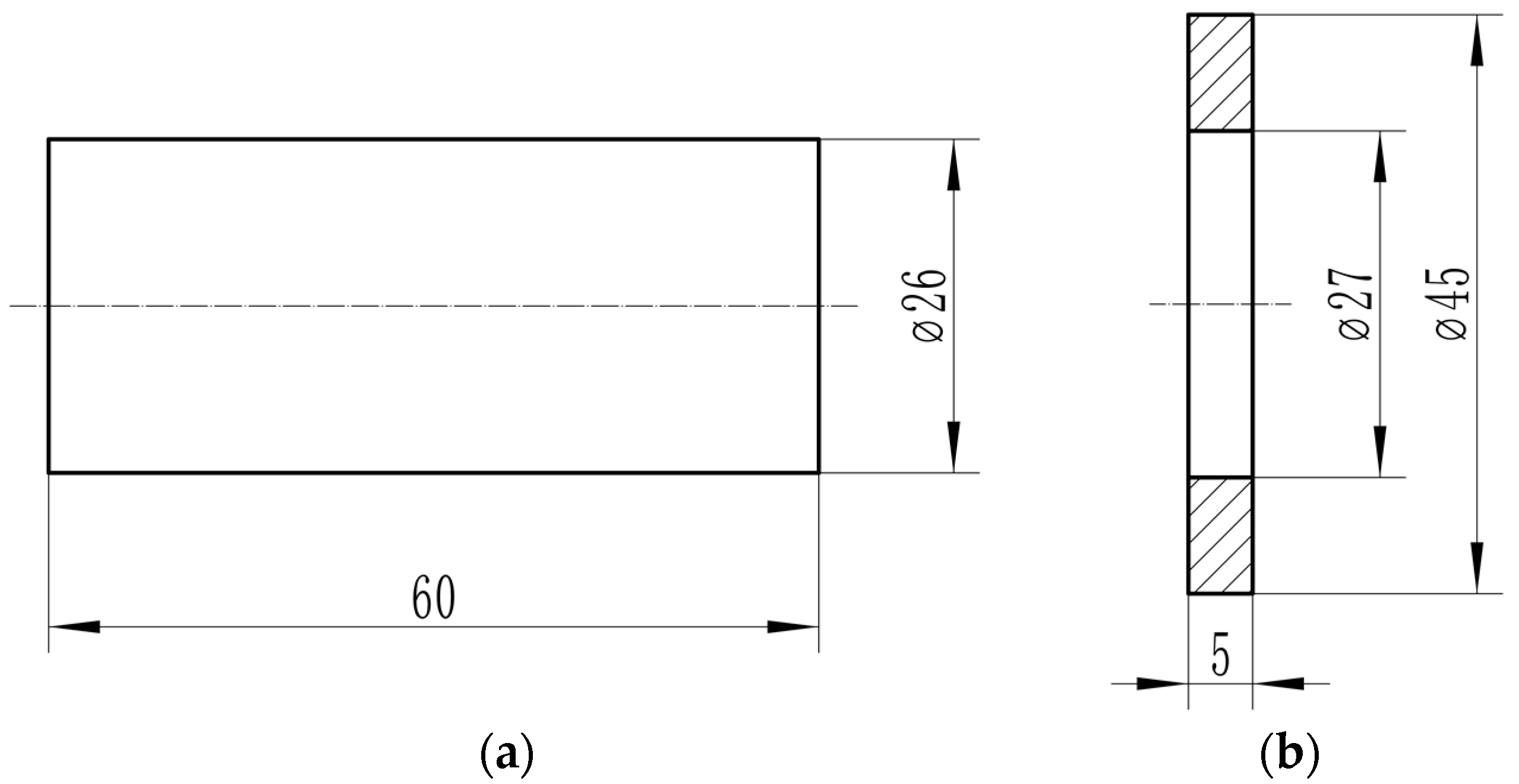
Figure 1. Aluminum/steel weldment structure and size: (a) 30CrMnSiA steel rod. (b) 6061-T6 aluminum alloy ring.
Metals 12 02023 g001
Figure 2. Variation of welding parameters in inertia radial friction welding (IRFW).
Metals 12 02023 g002
Figure 3. Aluminum/steel IRFW diagram.
Metals 12 02023 g003
Figure 4. Aluminum/steel test sample and shear tooling: (A) Metallographic sample and shear sample; (B) Shear tooling.
Metals 12 02023 g004
Figure 5. Aluminum/steel joint shearing experiment method.
Metals 12 02023 g005
Figure 6. Macromorphology of the aluminum/steel IRFW joint: (A) Sample appearance; (B) Drawn cross-section.
Metals 12 02023 g006
Figure 7. Macromorphology of aluminum/steel joint after mechanical tearing under different parameters: (a) Friction speed; (b) Friction pressure; (c) Upsetting pressure.
Metals 12 02023 g007
Figure 8. Cross-sectional microstructure of the aluminum/steel joint: (A) Joint appearcance; (B) Larger view of (A); (C) Larger view of (c in (B)); (D) Larger view of (d in (B)).
Metals 12 02023 g008
Figure 9. Micromorphology and energy spectrum of the aluminum/steel welding interface under different welding parameters: (A) Sample 3 welding interface; (B) Sample 2 welding interface; (C) Sample 5 welding interface; (D) Sample 1 welding interface; (E) EDS at point 1 in (A); (F) EDS at point 2 in (B).
Metals 12 02023 g009
Figure 10. Composition scanning and XRD pattern of the aluminum/steel welding interface: (A) Sample 5 area scanning and line scanning position; (B) Line scanning pattern; (C) XRD pattern; (D) Al element; (E) Fe element; (F) Si element.
Metals 12 02023 g010
Figure 12. Micromorphology and chemical composition of the steel-side shear fracture: (A) Sheared specimen; (B) Larger view of (A); (C) Larger view of (B); (D) EDS of (C).
Metals 12 02023 g012
Figure 13. Microhardness distribution of the aluminum/steel joint under different welding parameters: (A) Microhardness test position; (B) Microhardness distribution curve.
Metals 12 02023 g013
Figure 14. Formation mechanism of the aluminum/steel welding interface structure: (A) Aluminum alloy plastic deformation; (B) Element diffusion and formation of the Al−Fe phase; (C) Si element aggregate and formation of the Al−Fe−Si phase.
Metals 12 02023 g014
Table 1. Chemical composition of 30CrMnSiA steel and 6061-T6 aluminum alloy.
Base MetalChemical Composition (wt.%)
FeAlCMnSiCrNiCuMgZnTi
30CrMnSiABal0.28~0.350.80~1.100.90~1.200.80~1.10≤0.40
6061-T60.70Bal0.150.40~0.80.04~0.350.15~0.400.8~1.20.250.15
Table 2. Welding parameters of aluminum/steel IRFW.
NumberFriction Speed R
(rpm)
Friction Pressure P1
(MPa)
Upsetting Pressure P2
(MPa)
1150027
2160027
3170027
416001.57
516002.57
6160037
7160023
8160025
9160029
Publisher’s Note: MDPI stays neutral with regard to jurisdictional claims in published maps and institutional affiliations.