Article

Effect of Temperature on Corrosion Behavior and Mechanism of S135 and G105 Steels in CO2/H2S Coexisting System

1
Exploration Department, Tianjin Branch of CNOOC (China), Limited, Tianjin 300459, China
2
State Key Laboratory of Oil and Gas Reservoir Geology and Exploitation, Southwest Petroleum University, Chengdu 610500, China
3
School of New Energy and Materials, Southwest Petroleum University, Chengdu 610500, China
*
Author to whom correspondence should be addressed.
Metals 2022, 12(11), 1848; https://doi.org/10.3390/met12111848
Submission received: 6 September 2022 / Revised: 25 October 2022 / Accepted: 25 October 2022 / Published: 29 October 2022
(This article belongs to the Special Issue Corrosion Detection and Protection of Steel Pipelines)

Abstract

:
The corrosive environment of oilfield condensate water was simulated at different temperatures with CO2/H2S. Weight-loss corrosion tests were conducted on S135 and G105 steels at different temperatures. The corrosion rates of the S135 and G105 were measured at room temperature, 100 °C and 180 °C. The phase structure of the corrosion products and the corrosion morphologies of the samples were characterized. The results show that the corrosion rates of the S135 and G105 increased at first and then decreased with the increase in temperature. The corrosion rates peaked at 100 °C, reaching 0.8463 mm/y and 0.8500 mm/y, respectively. CO2 was the main controlling factor in the corrosion. The corrosion products were FeS and FeCO3. The corrosion rate at room temperature was lower than that at 100 °C. The corrosion rate at the temperature of 180 °C was the lowest. The corrosion rates of the S135 and G105 were 0.2291 mm/y and 0.2309 mm/y, respectively. CO2 was not the main controlling factor in the corrosion. The corrosion product was FeS. High temperatures aggravated the carbon-steel corrosion further in the environment with the high concentration of CO2 and a loose corrosion-product film formed. The dense and uniform FeS corrosives formed and attached to the surface of the substrate, and inhibited corrosion. Dense and uniform FeS products formed on the surface of the steel with the increase in temperature. A small amount of H2S inhibited the progress of the corrosion.

1. Introduction

In the process of oil and gas exploration and development, tubing, casing and drill-string materials often face the corrosion problems of CO2 and H2S, especially for the middle- and deep-reservoir fluids in Bohai Oilfield (China), which generally contain CO2, H2S and other corrosive gases. This increases the wellbore risk and well-control risk, creating higher corrosion-resistance requirements for downhole tools. With the continuous expansion of deep exploration and natural-gas exploration in Bohai Oilfield, increasing numbers of wells containing CO2 or/and H2S and various corrosive gases have been discovered, resulting in significant hidden dangers to the wellbore stability and safety belts with high temperatures, high pressure and highly corrosive gas conditions during the test. Based on the short test time, ordinary high-strength carbon steels, such as S135 and G105, often used in the test stage. These materials still suffer from severe corrosion at high concentrations of CO2/H2S corrosive gas and in high-temperature underground environments. The temperature of each section of the wellbore is different and the corrosion of the pipe strings at different temperatures is unstable. CO2 easily causes pitting corrosion in pipe-string materials [1,2,3] and H2S leads to a faster dissolution of iron [4]. CO2 and H2S cause huge economic losses through the corrosion of tubing and casing-string materials and the development of the oil and gas field [5,6].
The corrosion degree due to the coexistence of CO2 and H2S mainly depends on the corrosion products, such as iron carbonate and ferrous sulfide, formed on the surface of the metal. The dense ferrous-sulfide corrosion product has resistance to the penetration of electrochemically active substances during the corrosion process. The role of iron sulfide is mainly in the corrosion-reaction products of H2S and the metal-matrix material. In systems with high concentrations of CO2 content, a small amount of H2S in the environment can inhibit the CO2 corrosion of steel materials, which has also been reported in the literature [7,8,9]. Zhao et al. [10] pointed out that the precipitation rate of iron-carbonate and iron-sulfide corrosion products or the formation of anti-corrosion layers are affected by various environmental factors, including the concentration of CO2 and H2S in the medium and the ambient temperature. The protection and adhesion of the corrosion products formed on the surfaces of carbon steel determine the corrosion rate of the matrix [11,12,13].
Several reports have been presented on corrosion and the corrosive behavior characteristics of metal materials under CO2 and H2S [14,15,16]. Eˇskinja et al. [17] only studied the effects of temperature and exposure time on the corrosion behavior of a ferritic steel in single CO2 environment. Moreover, long immersion tests and electrochemical measurements were performed to study the effect of time and temperature on the CO2 corrosion of the ferritic steel. This cannot be used to simulate the actual corrosive environment. Although the corrosion of carbon steel in environments in which two corrosive gases CO2/H2S coexist is also reported, the research is relatively shallow. A systematic and complete theoretical system has not been formed. Therefore, based on the CO2/H2S corrosive environment in a well in Bohai Oilfield, the corrosion behaviors and laws of different well-section temperatures on common test string materials, such as S135 and G105 steel, are systematically studied in this work. The effect of temperature on the corrosion characteristics and mechanism is explored in depth. This provides a theoretical basis for the selection and design of oilfield test strings.

2. Experimental Methods

2.1. Samples

S135 and G105 steels were used as the testing samples, which were cut from high-strength finished drill pipe provided by Bohai Oilfield (Tianjin, China). The chemical compositions of the samples provided by the manufacturer of the pipes are shown in Table 1. According to the ASTM standards, all specimens were machined to a size of (30 ± 1) mm × (10 ± 0.5) mm × (3 ± 0.2) mm and 4 parallel samples in each group were prepared for each material. The size of the corrosion coupon is shown in Figure 1a and the macroscopic appearance of the corrosion coupon is shown in Figure 1b. Here, Figure 1b only presents the macroscopic appearance of the test specimens S135. The samples were polished to 2000 mesh with sandpaper and then washed with deionized water, degreased with acetone, rinsed with absolute ethanol, dried with cold air and placed in the drying box for use.

2.2. Methods

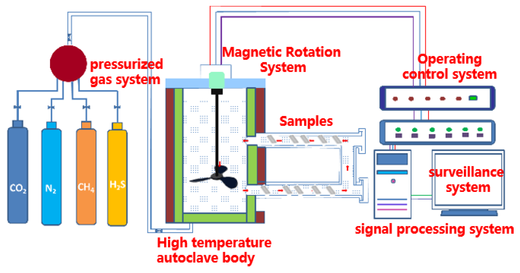
The self-developed high-temperature and high-pressure (HTHP) autoclave used in the weight-loss test is shown in Figure 2. The maximum test pressure of the HTHP autoclave equipment was 70 ± 2 MPa, the maximum temperature was 350 ± 5 °C and the volume of the HTHP autoclave was 8 ± 0.5 L. The experimental solution was the formation water from a domestic oilfield, and its composition was 2.01 g/L Na2CO3, 0.39 g/L NaCl, 2.23 g/L Na2SO4, 24.65 g/L NaHCO3, 3.20 g/L CaCl2, 3.96 g/L MgCl2 and 32.27 g/L KCl.
The test-piece rack with the hung sample was placed in the autoclave after adding the prepared simulated-formation aqueous solution into the HTHP autoclave. Firstly, it was deoxygenated with nitrogen for 2 h, after which CO2 and H2S gas were introduced. The pressure was added to the set pressure value with nitrogen after the temperature reached the set value. When the experiment time was up, the test samples were taken out and classified. One sample of each steel was used for the phase-structure analysis and morphology observation of the corrosion products. The corrosion products on the surfaces of the three remaining samples were removed by the solution prepared with deionized water (100 ± 0.5 mL), hydrochloric acid (10 ± 0.1 mL) and hexamethylenetetramine (5 ± 0.01 g) and then rinsed with deionized water and acetone. The cleaned samples were blown by cold air for 10 min and placed in a drying oven at 60 °C for 1 h. After they were fully dried, the samples were taken out for weighing and the corrosion rate was calculated. The surface macroscopic appearance of the samples was photographed.
The mass of samples was weighed in an electronic balance with a precision of 0.1 mg at the pre-test and post-test, after which the weight value was recorded. According to the NACE RP0775-2005 standard, the corrosion rate was calculated as in Equation (1) [18,19].
υ = 8.76 × 10 4 · Δ m S t ρ
where: υ   is the corrosion rate per year (mm/y); Δm is the weight loss (g); ρ is the material density (g/cm3); A is the total exposure surface area (cm2); and Δt is the total exposure time (h).
The specific testing schemes of the HTHP corrosion test are shown in Table 2. The phase composition of the corrosion products on the surface of the samples was investigated using a Siemens diffractometer (Siemens, Munich, Germany) operating at 45 kV and 40 mA with Cu Kα radiation (wavelength λ = 0.15406 nm). The 2θ ranged from 10° to 90°, using a scan rate of 0.01°/min. A scanning electron microscope (ZEISS EVO MA15, Carl Zeiss, Oberkochen, Germany) with an energy-dispersive X-ray system (EDX, Oxford, London, UK) was used to analyze the surface microscopic topography of the corrosion products and the sample surface after the corrosion products were removed and the elemental compositions were also tested. Before the characterization of morphology, gold was sputtered on the surfaces of the samples, so as to prevent the specimens from charging.

3. Results and Discussion

3.1. Weight-Loss Corrosion Rate

According to the experimental design in Table 2, the HTHP autoclave was used to carry out the corrosion test. The corrosion rate of the S135 and G105 steels is shown in Figure 3. It can be seen from Figure 3 that the corrosion rates of the S135 and G105 steels at room temperature and 100 °C were much larger than the minimum value of severe corrosion in NACE RP0775, which is 0.254 mm/y. When the temperature was 180 °C, the corrosion rates of the two steel-drill-pipe materials was between 0.126 and 0.254 mm/y, suggesting serious corrosion. At room temperature, the corrosion rate of the S135 steel was higher than that of the G105, but with the increase in the temperature, the corrosion of the G105 steel was slightly faster than that of the S135 steel at 100 °C and 180 °C. The maximum corrosion rate of the two steels was 100 °C, indicating that the most serious corrosion occurred at this temperature, followed by room temperature.

3.2. Composition of Corrosion Products

In order to analyze the corrosion products formed on the surfaces of the samples in the simulated well environment, the XRD spectra of the corrosion scales of the S135 and G105 steels were detected, as shown in Figure 4. From Figure 4, it can be seen that the characteristic diffraction peak of the corrosion products formed on the surfaces of the S135 and G105 steels at room temperature was completely consistent with the standard atlas of FeS (JCPDS 76-0960). Therefore, the corrosion products were mainly FeS. Based on the standard atlas of FeCO3 (JCPDS 83-1764) and FeS (JCPDS 76-0960), the corrosion products were FeCO3 and FeS when the temperature rose to 100 °C. However, the corrosion products were only FeS after the temperature continued to rise to 180 °C. Combined with the results of the corrosion rates, it can be seen that severe corrosion occurred at the temperature of 100 °C and that the formed corrosion products were FeCO3, FeS and FeCO3. FeCO3 was formed by the reaction of CO2 in the environment with the base metal, indicating that the main controlling factor in carbon-steel corrosion is temperature. As the temperature rose to 180 °C, the corrosion products were mainly FeS and the matrix Fe, according to the standard atlas of Fe (JCPDS 33-0397), indicating that the main controlling factor in material corrosion is H2S at this temperature.

3.3. Surface-Morphology Observation

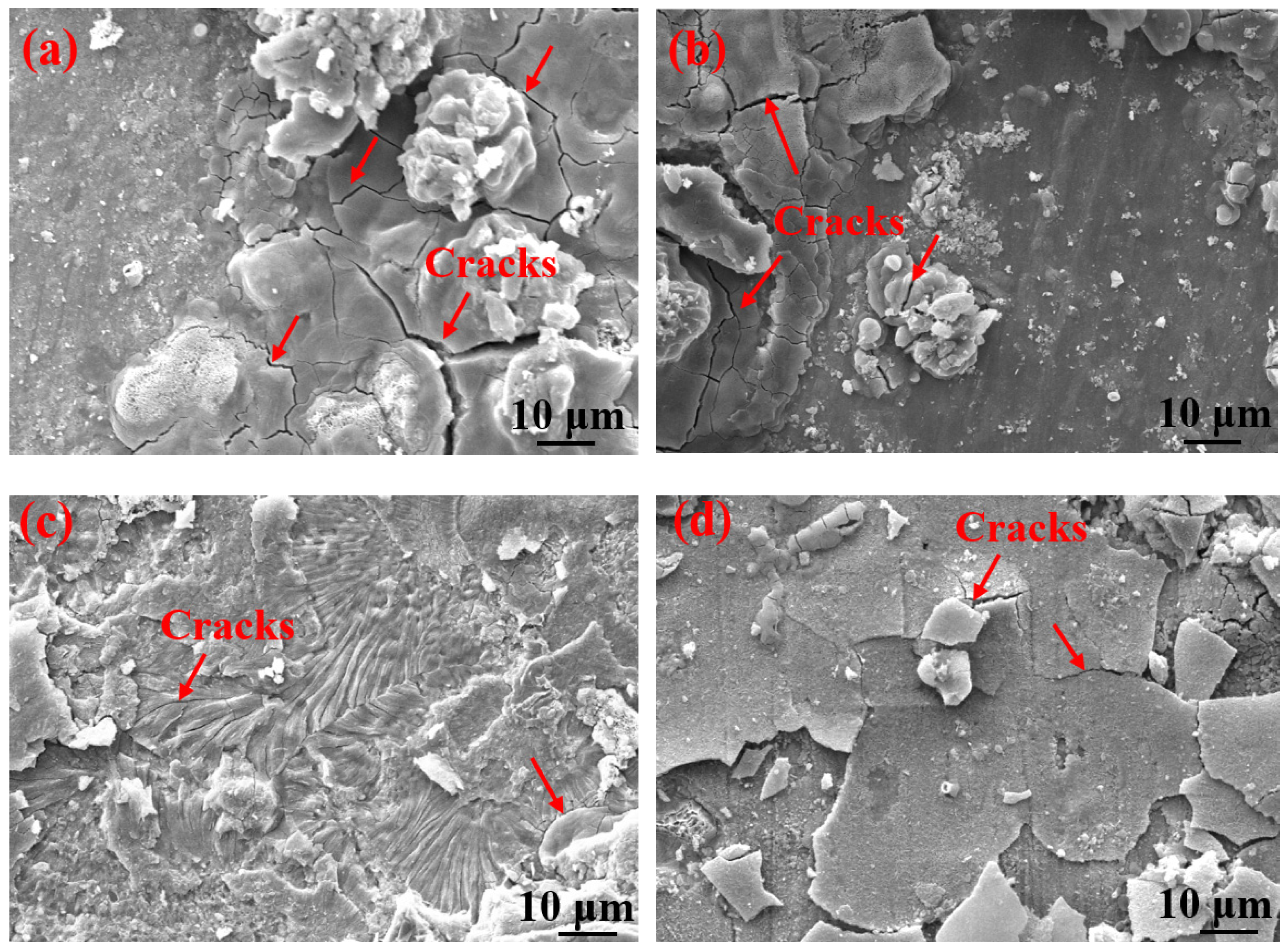
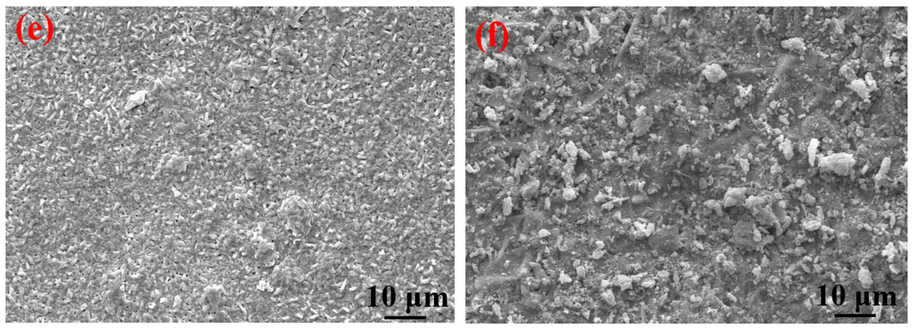
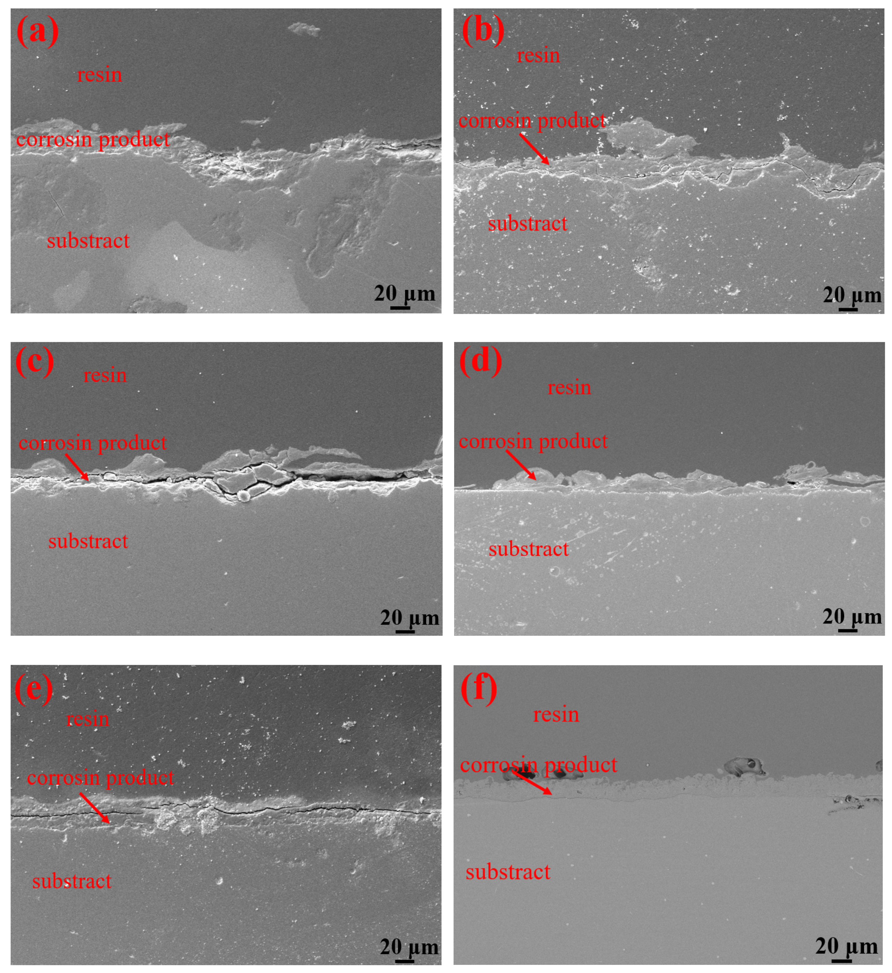
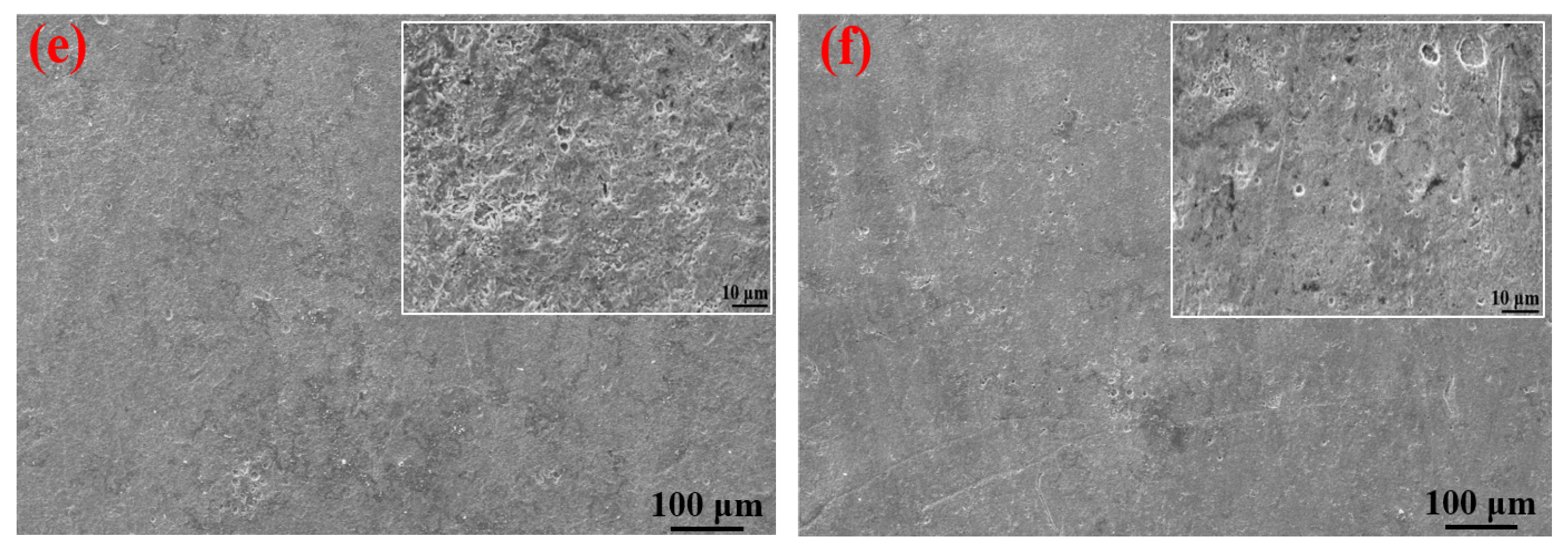
Table 3 shows the macroscopic surface morphologies of the S135 and G105 samples after corrosion at different temperatures. The corrosion products formed on the coupons were uneven and peeled off at room temperature and 100 °C. After the corrosion products were removed, some pits appeared on the coupons, as shown by the red arrows in Table 3. The samples were corroded at the temperature of 180 °C; the corrosion products formed on the coupons were relatively flat. After removing the corrosion products, there was no pitting pit. Figure 5 presents SEM images of the corrosion products of the S135 and G105 at different temperatures. In Figure 5, it can be seen that the corrosion products formed on the surfaces of the S135 and G105 at room temperature and that the granular corrosion deposits combined on the surfaces. The corrosion products were seriously cracked, as shown by the red arrow in Figure 5. The corrosion products formed at 100 °C also cracked seriously and some of the corrosion products experienced significant cracking and fell off. The loose corrosion products fell off and obvious cracks formed on the surface of the substrate. This was due to the hydrogen-induced cracking and sulfide-corrosion cracking caused by the hydrogen sulfide’s intrusion without the protection of dense-corrosion-product film [11]. The corrosion products formed at 180 °C were relatively flat and dense and arranged in a wheat-spike-like form; no obvious holes and cracks appeared. The corrosion products generated at room temperature and 180 °C were mainly FeS. It is well known that FeS is a dense corrosion product and it had a certain corrosion-inhibition effect on the substrate [20,21]. The corrosion products generated at 100 °C were mainly FeCO3 and FeS and the amount of FeCO3 with loose porous corrosion product was greater. FeCO3 is a loose and porous corrosion product [22,23]; therefore, the substrate material at this temperature was more susceptible to corrosion. Figure 6 presents SEM cross-section images of the corrosion products of the S135 and G105 at different temperatures. From Figure 6, it can be clearly observed that corrosion with many cracks took place at room temperature and 100 °C, especially at 100 °C. Because the corrosion product cracked and fell off at 100 °C, it was observed that the thicknesses of the products at 100 °C were 9.75 ± 0.19 μm for the S135 and 11.3 ± 0.22 μm for the G105, respectively. These were thinner than those of the S135 (21.5 ± 0.27 μm) and G105 (22.8 ± 0.32 μm) at room temperature. The obvious cracks provided channels for H2S, CO2 and Cl from the environment to enter the matrix. Therefore, severe corrosion occurred at this temperature. However, the corrosion products produced at 100 °C were dense and uniform and no obvious cracks were found, which had a good anti-corrosion effect on the matrix material.
It can be clearly seen from Table 4 that the elements contained in the corrosion products formed on the surfaces of the S135 and G105 steels under the three temperature conditions were mainly C, S, Fe and O. The contents of C and O in the corrosion products at 100 °C were significantly higher than those of the corrosion products at room temperature and 180 °C. A small amount of Cl element was also detected in the corrosion products at 100 °C, in the form of chloride ion, forming occluded battery corrosion and intensifying the corrosion process of the substrate [24]. This indicates that the main corrosion product formed at 100 °C was FeCO3, which is consistent with the XRD-analysis results. At this temperature, the Cl from the formation water aggravated the progress of the CO2 corrosion. Yue et al. [25] found that a loose, porous and poorly protective FeCO3 film formed on the surface of the metal substrate in the CO2 system. When the corrosion system contained H2S, a uniform and dense FeS film formed, significantly reducing the corrosion rate of the steel matrix. It is obvious from the microscopic topography of the sample after removing the corrosion products in Figure 7 that many corrosion pits were distributed on the surface of the coupon after removing the corrosion products; in particular, the number of corrosion pits peaked on the coupon surface at 100 °C. The dense corrosion pits connected to each other to form large flake-ulcer-like corrosion and developed into large corrosion pits. At 100 °C, large corrosion pits formed on the surfaces of the coupons. The corrosion pits at room temperature were smaller than those formed at 100 °C. The number of corrosion pits on the surface of the sample corroded at 180 °C was the lowest, which was consistent with the calculated corrosion rate. Moreover, it was consistent with Wu et al. [26]’s finding that in environments containing only CO2, the corrosion rate of carbon steel increases with the increase in temperature, but in the presence of H2S, the corrosion rate decreases with the increase in temperature.

3.4. Corrosion Behavior and Mechanism

Under the coexistence of CO2 and H2S, the corrosion state of materials depends on the ratio of CO2/H2S. The presence of a small amount of H2S has a certain inhibitory effect on CO2 corrosion [27]. According to the research results reported by Schmitt [28] and Guenter [29], the corrosion state of materials mainly depends on the ambient temperature in the coexistence of CO2 and trace H2S. Zhao et al. [30] found that at room temperature, H2S is more likely to react with metal materials to form corrosion products of FeS than in CO2 environments. Since FeS has self-healing ability, it can repair pitting corrosion, and the protection it offers the metal matrix contributes to the electric-field-force-induced ion migration. The strong chemical affinity of S to Fe promotes the rapid formation of dense FeS film on the surface of high-strength carbon steel in environments with H2S/CO2. Yin et al. [21] proposed that the corrosion rates, corrosion kinetics and corrosion products of the metal matrix were greatly altered in an environment with CO2 and H2S. Corrosive media such as HS and Cl rapidly penetrate to the matrix and react with it at low temperatures. Moreover, the penetration rate increases with the increase in temperature, which activates and accelerates the medium activity in view of the thermodynamics and kinetics. Beyond the temperature, protective film forms and effectively inhibits the diffusion transformation of the corrosion medium between the bulk solution and the substrate surface. This reduces the corrosion rate.
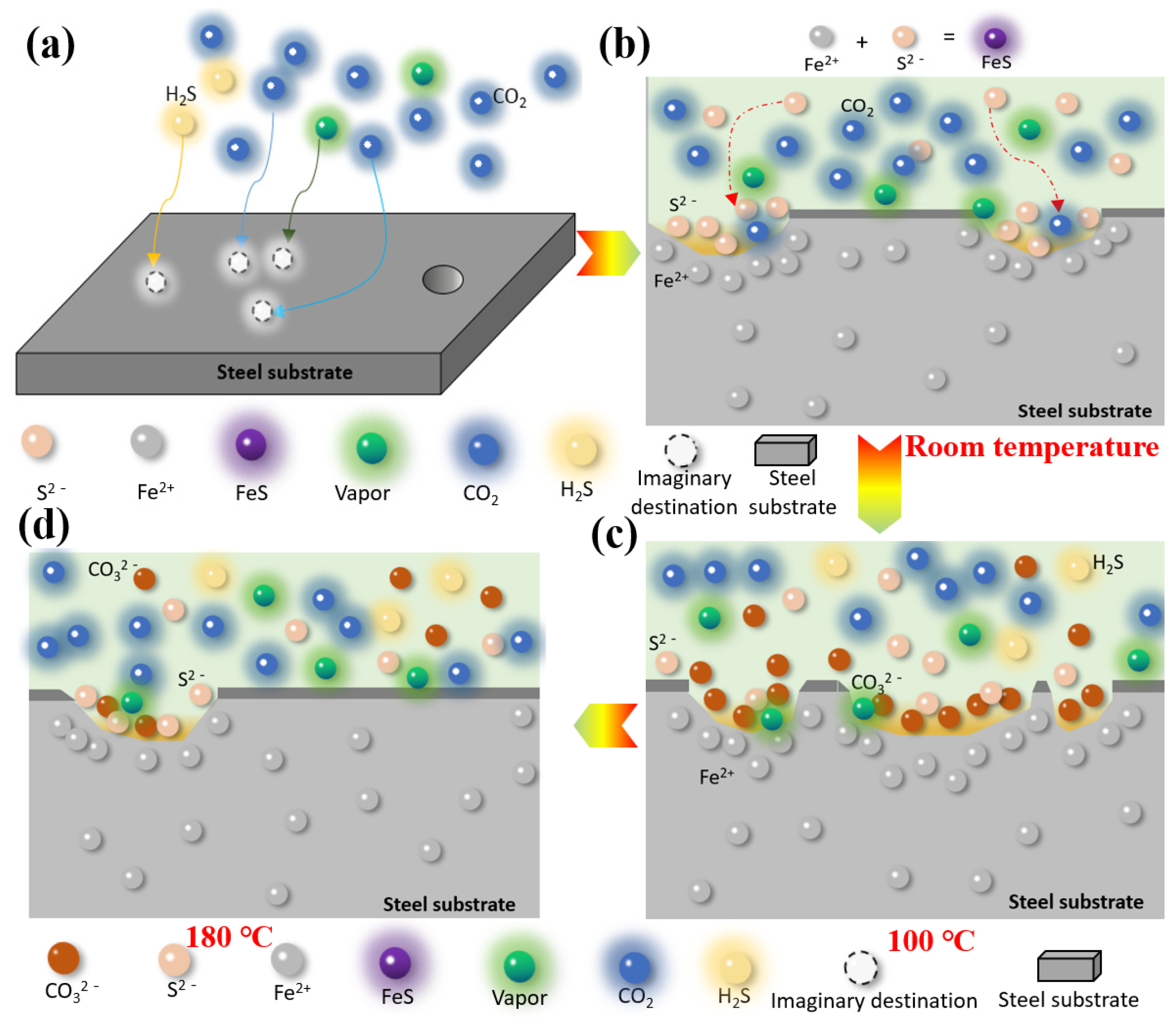
According to the results of the weight-loss corrosion test, the S135 and G105 steels were severely corroded at room temperature and 100 °C. They displayed relatively weak corrosion at 180 °C and the corrosion was the most significant at 100 °C. Combining the corrosion rates of the S135 and G105 steels under the H2S/CO2 coexistence environments with different concentrations and the corrosion-product films generated under corresponding conditions, a corrosion-mechanism-model diagram of S135 and G105 steels under H2S/CO2 conditions is proposed in Figure 8. Temperature affects the formation of an adsorbed water film on the metal surface, which further affects the dissolution of the formed corrosion products, such as FeCO3.
H2S promotes the adsorption of H2O molecules on the steel surface, after which it forms a condensed water film on the surface of the carbon-steel material. The dissolution and dissociation of H2S in the water film produces S2−, HS and H+, resulting in matrix corrosion. The corrosion process can be represented by the following electrochemical reactions.
From Figure 8, it can be seen that the metal matrix dissolves at room temperature and that a FeS-corrosion-product film forms through the reaction of Fe2+ with S2−, which attaches to the surface of the matrix. FeCO3-corrosion products are generated through the gas-phase chemical reaction between CO2, H2O and the matrix Fe.
Under the room-temperature condition, since H2S was the main corrosion control factor, it was easier to corrode the metal material to form FeS compared to CO2, while the formed corrosion product, FeCO3, was reduced (as shown in Figure 8b). Therefore, the main substance, according to the XRD analysis results, was FeS species; FeCO3 was not detected.
With the continuous increase in the temperature in the solution environment, when the temperature rose to 100 °C, the nucleation rate of the corrosive crystals generated by the reaction was greater than the growth rate of the film (shown in Figure 8c). At this point, the CO2 in the condensate phase dissolved and dissociated into CO32−, which reacted with the Fe2+ to generate FeCO3. Simultaneously, the gas-chemical reaction of H2S occurred on the surface of the carbon steel to form FeS corrosive substances, which adhered to the surface of the substrate without the formation of a condensed-water film.
The corrosive FeCO3 crystals dissolved as the ambient temperature increased. The iron-carbonate film was loose and bonded poorly to the substrate. Therefore, some FeCO3 corrosives cracked and fell off and the steel substrate was exposed to the solution environment, which encouraged corrosion, as shown in Figure 5. When the temperature in the solution environment continued to rise and it rose to 180 °C, Fe preferentially interacted with H2S to form FeS, which acted as a protective barrier to inhibit the infiltration of CO2 and H2O molecules, preventing the corrosion of the matrix material. Therefore, under this temperature condition, the corrosion rates of the S135 and G105 were 0.2291 mm/y and 0.2309 mm/y, respectively. These were lower than those of the S135 (0.5166 mm/y) and G105 (0.3510 mm/y) at room temperature and the S135 (0.8463 mm/y) and G105 (0.8500 mm/y) at 100 °C. Li et al. [31] found that when the temperature was higher than 150 °C, H2S played a dominant role in the corrosion process. A dense FeS layer formed. Once the iron-sulfide layer completely covered the steel surface, the corrosion rate was controlled through the slow diffusion of the ionic (Fe2+ and S2−) FexSy layer and its chemical dissolution in the environment media with H2S and CO2.

4. Conclusions

(1)
The average corrosion rates of the S135 and G105 steels first increased and then decreased with the increase in temperature in the simulated-formation condensate-water environment containing corrosive CO2 and H2S gases. At 100 °C, the corrosion rates of the two steels peaked and the corrosion was at its most significant. Relatively low corrosion occurred at room temperature. At 180 °C, the corrosion rates of the two steels were at their lowest and the corrosion was the slightest.
(2)
In the CO2 corrosion environment with a small amount of H2S, the small amount of H2S inhibited the CO2 corrosion of the substrate steel at room temperature and 180 °C. The main corrosion product formed at these temperatures was denser FeS. At 100 °C, CO2 was the main controlling factor in the material corrosion. The corrosion products generated on the surface were mainly loose and cracked FeCO3 corrosion products, and many corrosion products fell off.
(3)
At room temperature, the corrosion rate of the S135 steel was much higher than that of the G105 steel. The corrosion rates of the two steels were similar with the increase in temperature. In the mixed environment of high CO2 content and low H2S content, the temperature played an important role in regulating the corrosion mechanism of the steel material. CO2 was dissociated into CO32− when the temperature increased to 100 °C. The adsorption of anions reduced and looser corrosion products of FeCO3 formed. The CO2 aggravated the corrosion degree significantly.

Author Contributions

Conceptualization, K.G. and S.S.; methodology, W.L.; software, Q.G.; validation, J.M.; formal analysis, S.S.; investigation, K.G.; resources, K.G.; data curation, W.L.; writing—original draft preparation, K.G.; writing—review and editing, Z.Z.; visualization, Q.G.; supervision, K.G. and Z.Z.; project administration, S.S.; funding acquisition, K.G. and W.L. All authors have read and agreed to the published version of the manuscript.

Funding

The authors are thankful to the exploration department of the Tianjin Branch of CNOOC (China), Limited, Tianjin (CCL2021TJT0NST0777), Sichuan Youth Science and Technology Innovation Research Team Project Plan (2020JDTD0016) and the scientific-research starting project, SWPU (2021QHZ013).

Institutional Review Board Statement

Not applicable.

Informed Consent Statement

Not applicable.

Data Availability Statement

Not applicable.

Conflicts of Interest

The authors declare no conflict of interest.

References

  1. Elgaddafi, R.; Ahmed, R.M.; Shah, S.N. Corrosion of carbon steel in CO2 saturated brine at elevated temperatures. J. Pet. Sci. Eng. 2021, 196, 107638. [Google Scholar] [CrossRef]
  2. Dong, B.; Liu, W.; Zhang, Y.; Banthukul, W.; Zhao, Y.; Zhang, T.; Fan, Y.; Li, X. Comparison of the characteristics of corrosion scales covering 3Cr steel and X60 steel in CO2-H2S coexistence environment. J. Nat. Gas Sci. Eng. 2020, 80, 103371. [Google Scholar] [CrossRef]
  3. Radwan, A.B.; Moussa, A.M.; Ai-Qahtani, N.H.S.; Case, R.P.; Castaneda, H.; Abdullah, A.M.; EI-Haddad, M.A.M.; Bhadra, J.; Al-Thani, N.J. Evaluation of the pitting corrosion of modified martensitic stainless steel in CO2 environment using point defect model. Metals 2022, 12, 233. [Google Scholar] [CrossRef]
  4. Yin, Z.; Zhang, Y.L.; Chang, G.R.; Yang, T.Q. Corrosion behavior and characteristics of 3Cr steel in coexisting H2S- and CO2-containing solutions. J. Mater. Eng. Perform. 2020, 29, 5442–5457. [Google Scholar] [CrossRef]
  5. Zeng, D.Z.; Dong, B.J.; Zeng, F.; Yu, Z.M.; Zeng, W.G.; Guo, Y.J.; Peng, Z.D.; Tao, Y. Analysis of corrosion failure and materials selection for CO2-H2S gas well. J. Nat. Gas Sci. Eng. 2021, 86, 103734. [Google Scholar] [CrossRef]
  6. Lu, Y.; Zhang, Y.; Liu, Z.G.; Zhang, Y.; Wang, C.M.; Guo, H.J. Corrosion control in CO2/H2S-produced water of offshore oil fields. Anti-Corros. Methods Mater. 2014, 61, 166–171. [Google Scholar] [CrossRef]
  7. Liu, B.; Zhao, H.; Li, F.; Guo, Y.; Zhang, J.; Zeng, W.; Yang, L.; Sun, H. Characterization and corrosion behavior of high-nitrogen HP-13Cr stainless steel in CO2 and H2S environment. Int. J. Electrochem. Sci. 2021, 16, 1. [Google Scholar] [CrossRef]
  8. Zhang, G.A.; Zeng, Y.; Guo, X.P.; Jiang, F.; Shi, D.Y.; Chen, Z.Y. Electrochemical corrosion behavior of carbon steel under dynamic high pressure H2S/CO2 environment. Corros. Sci. 2012, 65, 37–47. [Google Scholar] [CrossRef]
  9. Zhang, Z.; Zhou, X.Y.; Zeng, D.Z.; Zhang, J.Y.; Shi, T.H. Evaluation on chloride cracking of S135 high-strength drill pipe. Front. Adv. Mater. Eng. Technol. 2012, 636, 430–432. [Google Scholar]
  10. Zhao, X.; Huang, W.; Li, G.; Feng, Y.; Zhang, J. Effect of CO2/H2S and applied stress on corrosion behavior of 15Cr tubing in oil field environment. Metals 2020, 10, 409. [Google Scholar] [CrossRef] [Green Version]
  11. Zhang, N.Y.; Zeng, D.Z.; Yu, Z.M.; Zhao, W.T.; Hu, J.Y.; Deng, W.L.; Tian, G. Effect of temperature on corrosion behavior of VM110SS casing steel in the CO2/H2S coexistent environment. Int. J. Electrochem. Sci. 2018, 13, 4489–4503. [Google Scholar] [CrossRef]
  12. Ren, C.Q.; Zhu, M.; Du, L.; Chen, J.B.; Zeng, D.Z.; Hu, J.Y.; Shi, T.H. Two-metal corrosion of casing pipe joint in CO2/H2S environment. Int. J. Electrochem. Sci. 2015, 10, 4029–4043. [Google Scholar]
  13. Veleva, L.; Bonfil, D.; Bacelis, Á.; Feliujr, S.; Cabrini, M.; Lorenzi, S. Corrosion activity of carbon steel B450C and low chromium ferritic stainless steel 430 in chloride-containing cement extract solution. Metals 2022, 12, 150. [Google Scholar] [CrossRef]
  14. Agrawal, A.K.; Durr, C.; Koch, G.H. Sulfide films and corrosion rates of AISI 1018 carbon steel in saline solutions in the presence of H2S and CO2 at temperatures up to 175F. Corrosion 2004, 63, 1–18. [Google Scholar]
  15. Tang, J.W.; Shao, Y.W.; Zhang, T.; Meng, G.Z.; Wang, F.H. Corrosion behaviour of carbon steel in different concentrations of HCl solutions containing H2S at 90 °C. Corros. Sci. 2011, 53, 1715–1723. [Google Scholar] [CrossRef]
  16. Arenas-martinez, L.F.; Garcia-cerecero, G. Hydrogen sulfide corrosion of weld regions in API X52 steel. Ing. Investig. Tecnol. 2012, 13, 473–478. [Google Scholar] [CrossRef] [Green Version]
  17. Eškinja, M.; Moshtaghi, M.; Honig, S.; Zehethofer, G.; Mori, G. Investigation of the effects of temperature and exposure time on the corrosion behavior of a ferritic steel in CO2 environment using the optimized linear polarization resistance method. Results Mater. 2022, 14, 100282. [Google Scholar] [CrossRef]
  18. Zeng, D.; Dong, B.; Zhang, S.; Yi, Y.; Huang, Z.; Tian, G.; Yu, H.; Sun, Y. Annular corrosion risk analysis of gas injection in CO2 flooding and development of oil-based annulus protection fluid. J. Pet. Sci. Eng. 2022, 208, 109526. [Google Scholar] [CrossRef]
  19. Li, L.; Yan, J.; Wang, F.; Qin, B.; Chen, G.; Tang, Z.; Zhang, H.; Liao, L.; Wang, J. Comprehending the role of the S-phase on the corrosion behavior of austenitic stainless steel exposed to H2S/CO2-saturated liquid and vapor environments. Int. J. Hydrogen Energy 2021, 46, 19508–19522. [Google Scholar] [CrossRef]
  20. Zhang, C.; Vahdat, Z.A.; Lu, Y.; Zhao, J.M. Investigation of the corrosion inhibition performances of various inhibitors for carbon steel in CO2 and CO2/H2S environments. Corros. Eng. Sci. Technol. 2020, 55, 531–538. [Google Scholar] [CrossRef]
  21. Yin, Z.F.; Liu, L.; Zhang, Y.Q.; Wang, K.; Zhu, S.D. Characteristics and mechanism of corrosion film formation on antisulphur steels in CO2/H2S environments. Corros. Eng. Sci. Technol. 2012, 47, 138–144. [Google Scholar] [CrossRef]
  22. Bai, H.; Wang, Y.; Ma, Y.; Ren, P.; Zhang, N. Pitting corrosion and microstructure of J55 carbon steel exposed to CO2/crude oil/brine solution under 2–15 MPa at 30–80 °C. Materials 2018, 11, 2374. [Google Scholar] [CrossRef] [PubMed] [Green Version]
  23. Hua, Y.; Xu, S.; Wang, Y.; Taleb, W.; Sun, J.; Zhang, L.; Barker, R.; Neville, A. The formation of FeCO3 and Fe3O4 on carbon steel and their protective capabilities against CO2 corrosion at elevated temperature and pressure. Corros. Sci. 2019, 157, 392–405. [Google Scholar] [CrossRef]
  24. Luo, Z.; Zuo, J.; Jiang, H.; Geng, W.; Zhou, Y.; Lian, Z.; Wei, W. Inhibition effect of fluoride ion on corrosion of 304 stainless steel in occluded cell corrosion stage in the presence of chloride ion. Metals 2021, 11, 350. [Google Scholar] [CrossRef]
  25. Yue, X.Q.; Zhang, L.; Li, D.P.; Honda, H.; Lu, M.X.; Wang, Z.; Tang, X. Effect of traces of dissolved oxygen on the passivation stability of super 13Cr stainless steel under high CO2/H2S conditions. Int. J. Electrochem. Sci. 2017, 12, 7853–7868. [Google Scholar] [CrossRef]
  26. Wu, G.Y.; Gu, X.K.; Zhao, W.W.; Fan, R.; Mao, T. Corrosion behavior of carbon steel in H2S-CO2-H2O-methyldiethanolamine (MDEA) solution under the presence of chloride ions. Anti-Corros. Methods Mater. 2021, 68, 284–292. [Google Scholar] [CrossRef]
  27. Zhang, S.H.; Li, Y.R.; Liu, B.S.; Mou, L.M.; Yu, S.; Zhang, Y.Z.; Yan, X.Y. Understanding the synergistic effect of CO2, H2S and fluid flow towards carbon steel corrosion. Vacuum 2022, 196, 110790. [Google Scholar] [CrossRef]
  28. Schmitt, G. Fundamental Aspects of CO2 Metal Loss Corrosion. Part II: Influence of Different Parameters on CO2 Corrosion Mechanism. 2015. Available online: https://onepetro.org/NACECORR/proceedings-abstract/CORR06/All-CORR06/NACE-06112/118113 (accessed on 5 September 2022).
  29. Das, G. Influence of Hydrogen Sulfide on CO2 Corrosion in Pipeline Steel. Int. J. Eng. Res. Technol. (IJERT) 2014, 3, 2224–2228. [Google Scholar]
  30. Zhao, W.M.; Zhang, T.M.; Zhao, Y.J.; Sun, J.B.; Wang, Y. Hydrogen permeation and embrittlement susceptibility of X80 welded joint under high-pressure coal gas environment. Corros. Sci. 2016, 111, 84–97. [Google Scholar] [CrossRef]
  31. Li, K.; Zeng, Y.; Luo, J. Influence of H2S on the general corrosion and sulfide stress cracking of pipelines steels for supercritical CO2 transportation. Corros. Sci. 2021, 190, 109639. [Google Scholar] [CrossRef]
Figure 1. Specimens for the corrosion experiment: (a) sample processing size; (b) specimen macroscopic image and the sample number on the test specimens with number.
Metals 12 01848 g001
Figure 2. Schematic of the HTHP autoclave.
Metals 12 01848 g002
Figure 3. Corrosion rates of S135 and G105 drilling-pipe materials under different temperatures.
Metals 12 01848 g003
Figure 4. XRD spectrum of corrosion products of two test string materials under different temperatures: (a) room temperature; (b) 100 °C; (c) 180 °C.
Metals 12 01848 g004
Figure 5. SEM images of corrosion products on the surfaces of S135 and G105 samples at different temperatures: (a) S135, room temperature; (b) G105, room temperature; (c) S135, 100 °C; (d) G105, 100 °C; (e) S135, 180 °C; (f) G105, 180 °C.
Metals 12 01848 g005aMetals 12 01848 g005b
Figure 6. SEM cross-section images of corrosion products of S135 and G105 samples at different temperatures: (a) S135, room temperature; (b) G105, room temperature; (c) S135, 100 °C; (d) G105, 100 °C; (e) S135, 180 °C; (f) G105, 180 °C.
Metals 12 01848 g006
Figure 7. SEM images of S135 and G105 (after removing the corrosion products) at different temperatures: (a) S135, room temperature; (b) G105, room temperature; (c) S135, 100 °C; (d) G105, 100 °C; (e) S135, 180 °C; (f) G105, 100 °C.
Metals 12 01848 g007aMetals 12 01848 g007b
Figure 8. Corrosion models of carbon-steel materials in the environment with H2S and CO2 under different temperatures: (a) nucleation and growth of corrosion product film, (b) initial stage of product membrane damage, (c) severe damage of product membrane, (d) product membrane repair stage.
Metals 12 01848 g008
Table 1. Chemical compositions of S135 and G105 steels (wt.%).
ElementsCSiMnPSCrMoNiCuTiNbVAlFe
S1350.280.280.890.0080.0011.020.440.060.110.01<0.010.0050.025Balance
G1050.280.221.120.010.0040.870.180.030.030.01<0.010.005<0.015Balance
Table 2. Experimental schemes of HTHP corrosion experiment.
CO2/(MPa)H2S/(MPa)SolutionPhase StateTime/(h)Temperature/(°C)
200.1Formation water (1L)Simulated condensate72Room temperature
100
180
Table 3. Optical photographs of S135 and G105 materials after corrosion at room temperature, 100 °C and 180 °C, respectively.
StateRoom Temperature100 °C180 °C
S135G105S135G105S135G105
Un-Removal CorrosionMetals 12 01848 i001Metals 12 01848 i002Metals 12 01848 i003Metals 12 01848 i004Metals 12 01848 i005Metals 12 01848 i006
Removal
Corrosion
Metals 12 01848 i007Metals 12 01848 i008Metals 12 01848 i009Metals 12 01848 i010Metals 12 01848 i011Metals 12 01848 i012
Table 4. Elemental composition of corrosion products according to energy spectra of S135 and G105 at room temperature (wt.%).
ElementsCOSiSCaClCrFeAuTotal
Contents
Room
Temperature
S13510.556.070.2914.580.16-0.9949.1118.25100.00
G10512.238.850.0914.30--1.3850.7912.36100.00
100 °CS13515.398.520.0716.840.151.59-44.7912.65100.00
G10514.4612.150.138.240.711.25-45.5217.54100.00
180 °CS1357.645.790.0821.710.17-0.3450.8713.40100.00
G10512.487.390.2021.981.95-0.4342.6712.90100.00
Publisher’s Note: MDPI stays neutral with regard to jurisdictional claims in published maps and institutional affiliations.