Article

Dissimilar Dual Phase-Low Carbon Steel Joints by the GMAW Process Subjected to Impact Load

by
César M. Gómora
1,*,
Ricardo R. Ambriz
1,
Christian J. García
1,
Ismael Ruíz-López
2 and
David Jaramillo
1
1
Instituto Politécnico Nacional CIITEC-IPN, Cerrada de Cecati S/N Col. Sta. Catarina, Azcapotzalco, Mexico City 02250, Mexico
2
Pintura Estampado y Montaje S.A.P.I. de C.V. Avenida Concepción Beístegui 2007 Col. Zona Industrial Poniente, Celaya 38020, Guanajuato, Mexico
*
Author to whom correspondence should be addressed.
Metals 2022, 12(3), 404; https://doi.org/10.3390/met12030404
Submission received: 31 January 2022 / Revised: 18 February 2022 / Accepted: 23 February 2022 / Published: 25 February 2022
(This article belongs to the Special Issue Mechanical Properties Assessment of Alloys during Welding Process)

Abstract

:
Dissimilar welding used in the automotive area are possible joints with the GMAW process; however, its structural performance must be evaluated. The focus of this work is to study the microstructural–mechanical properties of dissimilar welding DPC340Y590T dual phase–JSC270C low carbon steels. Microhardness profile, tensile, and impact tests were used to evaluate the mechanical behavior, while optical and scanning electron microscopy were employed to evaluate the microstructural changes. The tensile strength was 540 and 275 MPa in dual phase and low carbon, respectively. Weld thermal cycles were obtained by means of K type thermocouples. The welding heat input generated martensite and grain growth in the dual phase heat affect zone, while grain growth and perlite phase increased in the low carbon heat affected zone. The variation in microhardness profile was produced by the presence of different phases, and the temperature at the end of dual phase heat affect zone was approximately 242 °C. During impact tests, the absorbed energies were 19.3, 50.7, and 50.2 J for low carbon, dual phase steel, and the welded dissimilar joint respectively. Finally, dissimilar welding subjected to tensile test failed in the low carbon steel (270 MPa), out of the heat affect zone, thus a good dissimilar joint between both steels was obtained.

1. Introduction

Systems in operation may sometimes present different working conditions that need to be designed under critical operating conditions; however, non-critical operating areas can be redesigned using lower cost materials, while maintaining the safety of the system. The joint between different materials has drawn attention in recent years, since they have a good cost–safety ratio. Due to their great versatility, dissimilar welds are applied in the chemical, nuclear, petrochemical, aeronautical, and automotive industries, where it is possible to weld metallic materials such as pipes, profiles, plates, and sheets of different chemical compositions [1,2]. However, the mechanical strength for the dissimilar joint must be characterized for proper design and safety requirements. Dissimilar joints are designed based on system requirements, since some irregularities can occur, such as the unmixed zone (laminar layer of base metal which has melted and resolidified in situ during the welding process) [3] between the electrode and the base materials due to the variation in chemical composition, diffusion of alloying elements that can generate an increase or loss of hardness in the interface between the bead of weld and the base material, or a non-homogeneous microstructure in the weld bead that can generate cracking due to the mixture of two different alloys. Failures could also be generated in the HAZ due to the gradient of the coefficient of thermal expansion that would increase the residual stresses at specific points [4].
The evolution of lightweight cars is a factor that has driven the development of new types of steels over the last decades. Advanced High Strength Steels (AHSS) [5,6] are the preferred steels used by automotive companies as they have a good stress-strain ratio. They are used in the automotive industry for structural parts, side panels, side members, and impact bars, in general, at specific points that can provide safety to passengers in the event of an impact [7]. In specific, the dual phase (DP) [8,9] families are some of the preferred steels used by automotive companies. These steels have characteristics that bring considerable advantages, such as good performance in collisions. It is important to note that the lightness of the vehicle leads to a decrease in fuel consumption, which is a strategy adopted by the automotive industry to reduce polluting emissions into the environment. In an automobile structure, the DP steels are be joined with AHSS and other types of steels with different thickness, such as the low carbon (LC) steel families, since LC steel can constitute 50 to 60% of the weight’s vehicle. The joints with dissimilar materials and thickness are indispensable, especially in safety issues related to new cars that will compete in the automotive business.
DP steels consist of a ferritic matrix containing a variable fraction of martensitic phase of high hardness. The fraction of the second martensitic phase can be increased to increase the strength of the DP steel. The soft ferritic matrix is generally continuous, providing excellent ductility. When these DP steels are conformed, the deformation concentrates on the soft ferritic phase, surrounding the islands of martensite, generating a high coefficient of hardening by deformation for these materials [10,11]. LC steels are a C-Mn alloy with ferrite–pearlite microstructures that poses a good ductility.
On the other hand, the weldability of these steels is a key aspect in terms of its applications. The study of the microstructural evolution and properties of the welded joint is a topic of great interest, especially in relation to the Gas Metal Arc Welding (GMAW) process, since it is used where it is not possible to apply the resistance spot welding process. For example, in closed structural profiles used in the automotive industry [12], Ahiale and Oh analyzed different dual phase steels (DP440 and DP590) and martensitic steel subjected to fatigue test. No significant differences were observed in the fatigue life to the different steels when they were welded by GMAW. Different welds obtained by GMAW process have been studied [13,14,15] to establish welding procedures that guarantee adequate mechanical properties for the welded joints between dissimilar components. Májlinger et al. [13] welded dissimilar joints between TWIP and TRIP steels using an austenitic steel filler at different welding parameters (voltage, current, and welding speed). They analyzed the welding quality and reported a ductil fracture inside fusion zone. Ramazani et al. [14] studied the microstructure of DP600 welded by GMAW. They reported a mixed condition consisting of bainite, ferrite, and tempered martensite for the heat affected zone. A soft zone was detected at 6 mm from the welding bead center, with a microhardness decrement of 31% with respect to the base material (175 HV1.0 kg). Additionally, Svoboda et al. [15] joined different DP steels by means of RSW, GMAW, and PAW process, and obtained welded joints with good quality. They reported the presence of a soft zone in all cases, which is attributed to the martensite tempered generated by the weld thermal cycle. In this sense, the weld thermal modifies the original ferritic–martensitic structure in the DP steel, generating variations of the properties in the Heat Affected Zone (HAZ). These changes are found to be associated with the tempering of the martensite, and are produced in the region from the reheated material to about 700 °C (sub-critical zone), generating the formation of a ferritic structure with carbides and low hardness, as reported by Kapustka et al. [16]. Macroscopic properties that depend upon the microstructure condition can be evaluated by means of static and dynamic tests. The first one, the tensile test, shows the stress that may support the dissimilar joint in a way that time has no effect. The second and third, the Charpy (which it is not possible to use in thin materials) and the free fall drop tests, can be used to evaluate the material response during a shock. A series of studies have been carried out on the fracture behavior of different steels, tested with different impact projectiles. Predrag et al. [17] analyzed the impact damage in thin plates (1.25 and 2.2 mm) of commercial steel (AISI 1008), and evaluated the residual velocity as a function of the impact velocity. They found that smaller plate thickness presented the largest residual velocities. Zhang et al. [18] also conducted a ballistic test where origami sandwich panels of aluminum were subjected to different shape projectiles impact. Flat-ended, hemispherical, and conical nose shapes were used. The results indicated that the hemispherical nose projectile had the smaller energy perforation. To the author’s knowledge, there are limited data in the literature for dissimilar welding joints of dual phase steel subjected to impact loading in free fall tower. Moreover, literature information regarding different thicknesses used in the dissimilar weld is limited.
The objective of this paper is to evaluate the response of dissimilar welded joints of LC and DP steel sheets of different thicknesses to impact tests. This work analyzes the microstructural evolution and the mechanical properties of the dissimilar welded joint, as well as the relation with the metallurgy phenomena and weld thermal cycles.

2. Materials and Methods

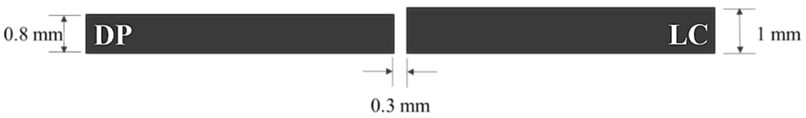
2.1. Materials and Welding

DPC340Y590T Dual Phase (DP) and JSC270C Low Carbon (LC) sheets with a respective thickness (t) of 0.8 and 1 mm were used for the experimentation. The chemical composition is shown in Table 1. The sheets were received under a commercial condition, which provided a Vickers hardness number of 187 ± 8 HV0.1 and 95 ± 4 HV0.1 for DP and LC steel, respectively. Sheets of 200 mm × 100 mm × t mm were prepared according to the joint geometry shown in Figure 1.
The GMAW process was used in conjunction with a ER70S-6 filler metal (0.9 mm in diameter), since this electrode, in addition to being commercial, has a tensile strength (482 MPa) that generates a balance between double phase (590 MPa) and low carbon steel (270 MPa), and has a chemical composition that is compatible with both materials. Distortion of the joint was mechanically prevented by restricting the sheets during welding. A mixture of Ar (98%) and O2 (2%) was used as the shielding gas, flowing at 1 m3 h−1. The welding parameters were experimentally determined: current (I) 24 A, voltage (V) 20 V, feeding speed 59.4 mm s−1, travel speed (v) 14 mm s−1, and stick–out 9 mm. Thermal efficiency was considered η = 80%. These welding parameters provided a heat input (Q) of 27.43 J mm−1 according to the Equation (1) [19]:
Q = η V I v

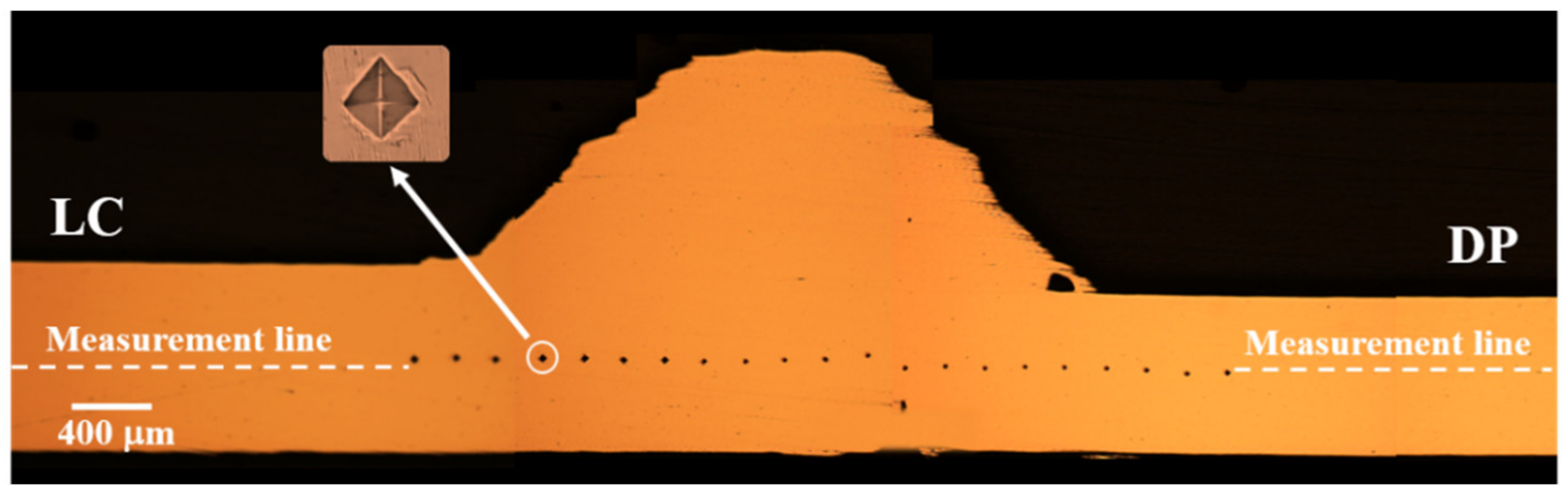
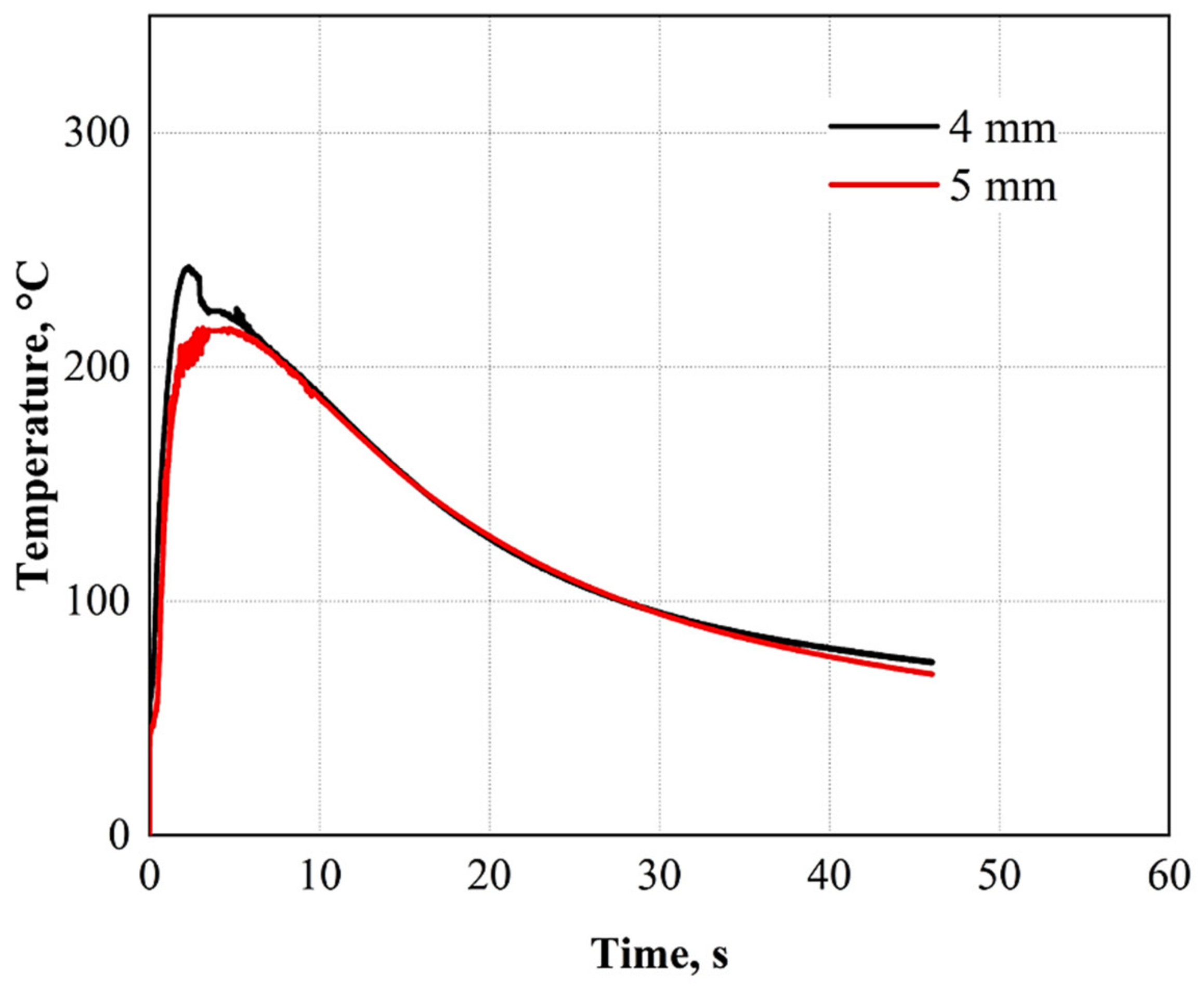
2.2. Weld Thermal Cycles

By means of K type thermocouples, weld thermal cycles in the HAZ were determined. These sensors were placed in direct contact with the top surface of the DP steel sheet at a distance of 4 and 5 mm from the center of the joint preparation. Figure 2 shows the location of the thermocouples. A National Instruments board NI 9213 with sampling rate of 100 Hz was used to collect the signal temperature using a LabVIEW program.

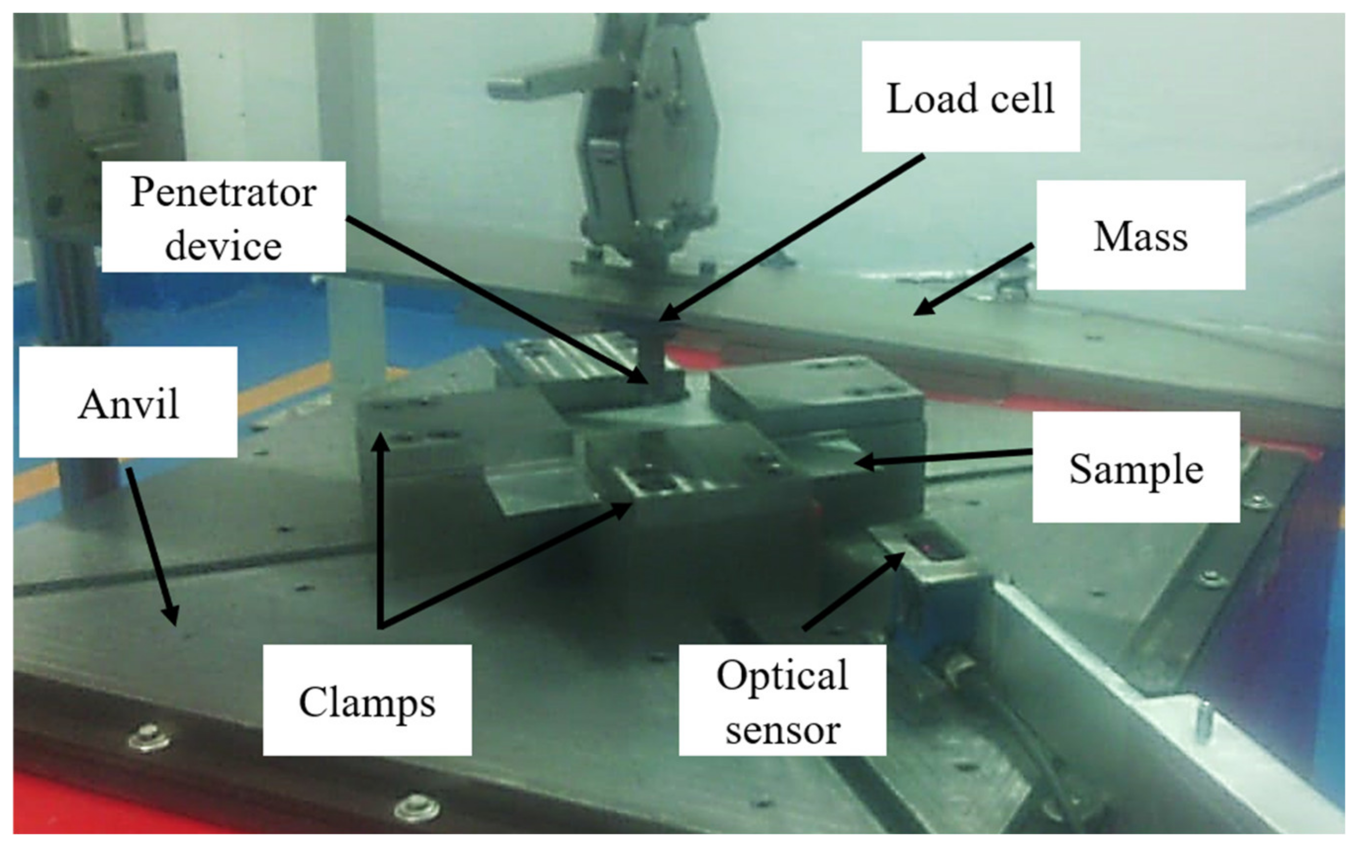
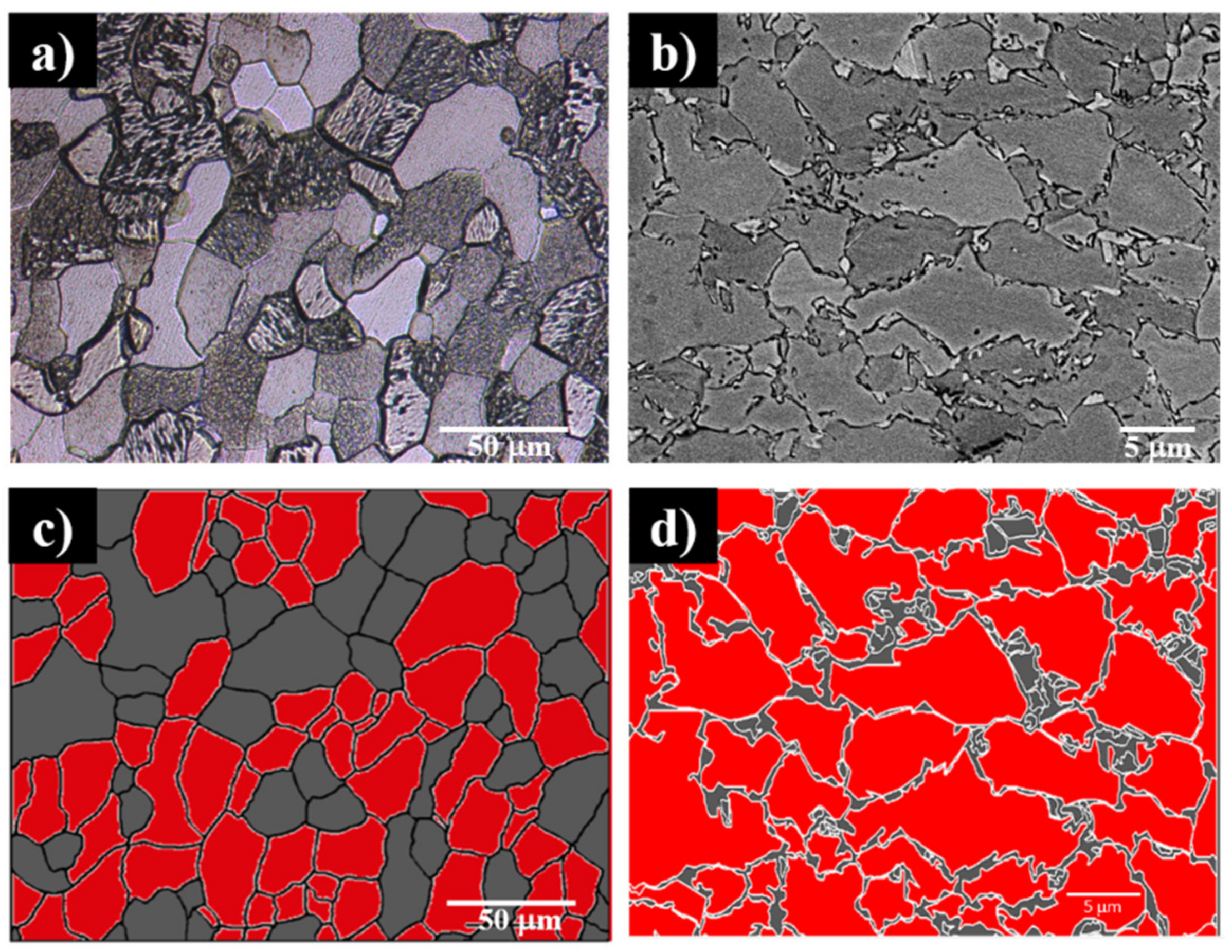
2.3. Mechanical and Microstructural Characterization

Microhardness measurements, tensile, and impact tests were performed to determine the mechanical properties of the DP–steel, LC–steel, and the dissimilar welding. The hardness variation along the welding profile was quantified by means of Vickers microhardness, following the line shown in Figure 3. The indentations were performed by using an indentation load of 981 mN (0.1 kg) and dwell-time of 15 s each 200 µm from the center of the welding bead to a distance of 5 mm. To determine the stress–strain behavior, standard tensile samples were machined according to the ASTM E8M standard [20].
Regarding the impact tests, samples of 200 mm × 200 mm were cut to conduct free-fall impact tests. Figure 4 shows the experimental arrangement where the tower elements are indicated. Initial conditions for the impact test were: mass 14 kg, elevation 1 m, potential energy 137.34 J, impact kinetics energy 137.34 J, and impact speed 4.429 ms−1.
For the microstructural study, foils were cut from the BMs and transversal samples were cut from the dissimilar welding, and then were enclosed in epoxy resin. The samples were ground gradually with silicon carbide sandpaper (No. 250, 400, 600, 800, 1000, 1200, 1500, and 2000) of different granulometry, and then mirror-finish polishing was performed using microfiber cloths with 3 and 1 μm diamond paste, for which a Minitech Z33 polishing machine was used. Subsequently, for the chemical attack, the samples were submerged in Nital 3% (produced from nitric acid and highly distilled alcohol) for a period of time of 3 and 60 s for DP and LC, respectively. For dissimilar welding, the chemical attack was realized gradually according to the microstructure. Scanning electron microscopy (SEM) and optical microscopy (OM) were used to analyze the different phases. The equipment used was an electronic microscope JEOL model JSM IT-300LV and an optical microscope Nikon model eclipse MA100, respectively.
Real microstructures (Figure 5a,b) were traced using polyline command in the AutoCAD software to obtain a well-defined grain boundary image that would quantify the number of grains present. The identification of phases was carried out by visual inspection and by means of manual processing: a specific color was assigned to each phase in the SigmaScan Pro5 software, maintaining the space relationship in the image through its equivalent in pixels. The number of total grains of each phase, there area, and the area of average grain size was determined through SigmaScan Pro5 software. Figure 5c,d shows the micrographs worked in the AutoCAD software, and each of the phases that compose them are indicated in a different color. For both cases, the red color identifies the ferrite, and the dark gray color is used to identify the perlite in the LC steel and the martensite in the DP steel.

3. Results and Discussion

Figure 6 shows the microstructure of the LC steel obtained by means of SEM. It should be noted that it consists of a typical microstructure for this LC steel; it has a ferritic matrix which gives it the property of ductility. On the other hand, there is the perlite phase that is constituted by ferrite and cementite, which promote the hardening of the material [21]. Table 2 shows the percentage of the phases presented in LC steel. According to ASTM E112 standard [22], 168.6 μm2 is equivalent to grain size G9.5, while 228 μm2 is equivalent to G9.
Figure 7 shows the microstructure of the DP steel. It can be seen that it has a ferrite phase matrix that provides ductility, and martensite phase islands that provides an increase in the mechanical strength. A minimum quantity of retained austenite has been reported in this steel [23]. However, it is not possible to observe it by means of microscopy. Table 2 shows the phases percentage in DP steel, ferrite grain size equivalent according to ASTM E112 is G12.5. Martensite has not equivalent grain size number, due to is very small size.
During the impact, the energy supplied was not enough to fracture the material and the welding. Figure 8 shows the strain vs. time behavior obtained from the LC and DP impact test. It can be seen that a maximum strain (23.3 µɛ) is generated at 3.04 ms in LC steel, and DP steel presents the highest strain (30. 3 µɛ) at 2.48 ms.
Force evolution during the test was obtained from Equation (2) [19]. It is worth mentioning that this expression is valid only for the tests performed in the free fall tower used:
F = m x + b = ( 1.6 ) μ ε 1.383
where µɛ is from Figure 8.
Figure 9 shows the force vs. time behavior for LC and DP steels, which has a maximum force (Fmax) of 36.02 kN at 2.8 ms and 47 kN at 2.5 ms, respectively. As can be seen, DP steel has a better impact behavior in terms of the supported reaction force. This is attributed to the combination of ductile phase (ferrite) and hard phase (martensite).
Figure 10 shows the displacement-time curve of the LC steel, where a maximum displacement (δ) of 4.5 mm is observed at 2.66 ms. In addition, for DP steel, the highest displacement was (δ) 4.6 mm at 3.2 ms; after this time, the material began to recover elastically.
Figure 11 shows the weld thermal cycles at 4 and 5 mm from the welding bead center on the DP side. It can be seen that the peak temperatures are 242 °C and 215 °C to 4 and 5 mm, respectively. These results are below Ac1 temperature, which means that tempered martensite phenomena could be present in the DP steel.
Uniform welding bead is showed in Figure 12a. Figure 12b presents the cross section of Figure 12a, where it is possible to observe macrostructural changes generated by the welding input heat. The areas showed are divided into Base Material (BM), grain refinement zone (GRZ), grain growth zone (GGZ), tempering base metal zone (TBMZ), and the fusion zone (FZ). The FZ contains martensite, acicular ferrite, and ferrite, as shown in Figure 13d. This is because the temperature reached the austenitization zone, generating a tempering, thus creating martensite. These microstructures are similar to those reported by Farabi et al. [24], who welded a DP600 steel by laser and observed martensite, ferrite, and bainite in the FZ. Ahiale et al. [25] found martensite, Widmanstätten ferrite, and acicular ferrite in the FZ. On the other hand, Ramazani et al. [11] reported ferrite and bainite microstructure in a welding of DP600 steel where a G3Si1 electrode was used. The areas analyzed are within the welding bead, and these changes may be mainly due to the change in chemical composition between the electrode used in this investigation and the one used by the latter authors.
The GGZ in DP steel (Figure 13C) presents a growth of grains. Ferrite, iron carbides, and martensite can be seen in large quantities. This change of microstructure is generated by the high temperatures reached when close to the welding bead. During the heating, it is possible to reach the austenitization temperature, and during a fast cooling, the different phases are transformed.
Figure 13B shows part of the GRZ, where finer grains regarding the base material can be seen; this is due to DP steel reaching temperature–time conditions to carried out the recrystallization, which generates small ferrite grains with small quantity of martensite. The DP HAZ presents different microstructural changes depending on the weld thermal cycle which was exposed. Works from the literature that used different welding processes have reported this microstructural variations [26,27]. In this sense, it is assumed that the microstructural changes depend on the temperature and dwell–time than the welding process. As can be seen in Figure 13A, the microstructure is similar to base metal (Figure 7), which means that insignificant microstructural transformations were carried out in DP steel.
Figure 13F,G show the interface and the adjacent area to the FZ corresponding to the LC steel. For the interface, some authors report an unmixed zone when filler and base materials exhibited improper mixing [4,28]. This leads to larger differences in the chemical composition. It is apparent that a partial unmixed zone (UZ) was present in the interface between the filler metal and LC steel, as observed in Figure 13F. A similar chemical composition (see Table 1) induces some proper mixing. Regarding the interface between the filler metal and DP, the unmixing zone was not detected (Figure 13D). For the adjacent area to the FZ, it can be seen that the grain growth of perlite and ferrite occurred. The presence of martensite is not possible since it is a very low carbon material (Table 1). Martensite is formed during tempering on other steels with more carbon, when the austenitization temperature is reached, followed by fast cooling. In this case, the austenitization temperature is reached, and an increase in austenitic grain size occurs, and during cooling, the austenite transforms into perlite and ferrite phases. These results are similar to those obtained by Romero et al. [29] and Reyes et al. [30], who reported that the transformation is carried out because during the welding process, the area adjacent to the welding bead reaches the highest temperatures in the base material, exceeding the A3 temperature; after that, during the cooling, the mentioned phases are presented. Figure 13I shows a ferrite–perlite as Figure 6. This means that, at this distance, there is not a heat effect.
Microstructural changes presented in Figure 13 are related to hardness changes, as shown in Figure 14. In the GGZ of LC steel, there is an increment in hardness, and the above is due to the increase in the perlite phase that is harder than ferrite. Following this last zone, the initial hardness of the base material is reached.
Regarding DP steel, the greatest hardness of the welded joint is found in the GGZ (401 HV0.1). As can be seen in Figure 13D, this area has the highest presence of the hardened martensite phase. This due to the high temperatures reached, followed by the uncontrolled tempering that takes place. Regarding the GRZ in DP steel, a slight increase in hardness can be noted, which is attributed to grain refinement, and the martensite formed during the fast cooling. At approximately 3 mm (inside the TBMZ), there is a slight drop in hardness, an area that some authors have called a subcritical zone. However, here, it cannot be defined as such.
In the study presented by Svoboda et al. [10], a variation of microhardness was found in the HAZ of different DP welding (DP500, DP700, and DP800). DP700 and DP800 steels presented a soft zone (subcritical zone) in their microstructure, below the initial hardness, while the DP500 steel with C-Mn chemical composition was less affected. This is attributed to the fact that the effect of hardening by the fraction of martensite in the DP500 steel was lower, and therefore did not show a loss of hardening. This leads to the idea that the more resistance to stress, the greater the effect of the loss of hardness in the area called subcritical zone.
Finally, at ~4 mm the microhardness stabilizes, indicating the end of the HAZ, at approximately 242 °C according to Figure 11, i.e., there are no microstructural changes. This is attributed to the fact that the peak temperature is far below Ac1 (~720 °C), and the d-well time is short.
Stress–strain LC, DP, and LC–DP behavior is shown in Figure 15b. The tensile tests were performed according to the ASTM E8M standard [20]. The fracture under the tensile test of the dissimilar weld is shown in Figure 15a. As can be seen, the right side corresponds to LC steel, where the fracture occurred at 29 mm from the center of the welding beam. The ultimate stress was similar to the LC steel (Table 3) since the failure occurred outside of the LC HAZ. In this sense, it could be said that the welded joint has an efficiency of 97%, with respect to low carbon steel.
Regarding the impact test, Figure 16 shows the front view of the dissimilar welding after the impact test, where the displacement of the material can be seen without presenting the fracture. However, a thickness reduction in the LC side close to the welding bead can be noticed, showing that the highest damage occurred in this zone. A microhardness map after the impact test was realized, according to the virtual mesh presented in Figure 16.
Figure 17 shows the microhardness distribution on the dissimilar welding after the impact test. It can be seen that microhardness increases due to strain hardening caused by the impact on the material. In addition, it is possible correlate the hardness behavior with phases distribution (Figure 13).
Figure 18 presents the strain vs. time behavior of dissimilar welding. It is possible to identify a maximum microstrain of 22.4 at 2.24 ms.—time correlation was realized by means of Equation (2). Maximum reaction force is 34.49 kN at 2.42 s (Figure 18).
In impact graphs, a different behavior from the rest of the curve usually appears in the first part. This is called the transient zone, which is where the applied load is transferred to the supports [31]. This idea is similar to the described by Field et al. [32], who explain that changes in the signal are produced by the mechanical resistance of the specimen. This is because the impact excites the weight below its resonance frequency, and then produces a rebound.
Figure 19 shows the displacement curve as a function of time in the dissimilar welding, which had a maximum displacement of 4.85 mm, and subsequently had an elastic recovery, where the final displacement was 1.73 mm.
To obtain the energy absorbed during the impact, data in Figure 9 and Figure 10 were used for LC and DP steel. In addition, Figure 18 and Figure 19 data were used for dissimilar welding (LC–DP). The absorbed impact energy for LC, DP, and LC–DP was 19.2, 50.7, and 50 J (which was determinate from Figure 20), respectively. The results indicate LC steel absorbs 14% of the energy impacted (137.44 J), while DP steel absorbs 37%, and LC–DP absorbs 36%. As can be seen, LC–DP absorbed 22% more energy than LC during the impact, showing a better response than LC and a similar response to DP, which is attributed to the good quality of the weld bead, which is free of pores or other imperfections that could decrease the welding bead resistance.

4. Conclusions

The main conclusions of this research work are the following:
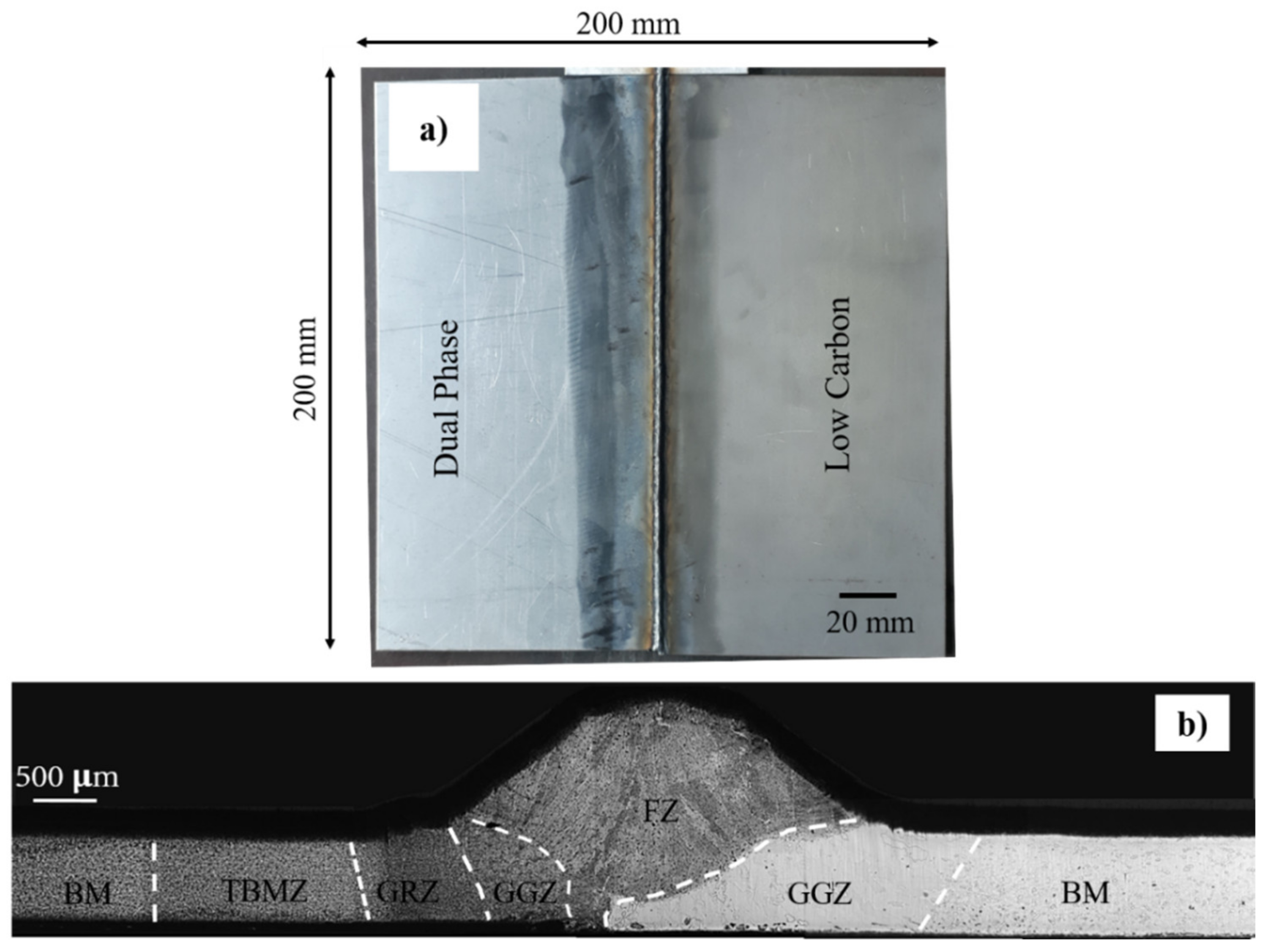
  • A dissimilar joint (dual phase and low carbon steel) of different base materials thickness (0.8 and 1.0 mm) with a uniform bead welding and complete penetration was obtained.
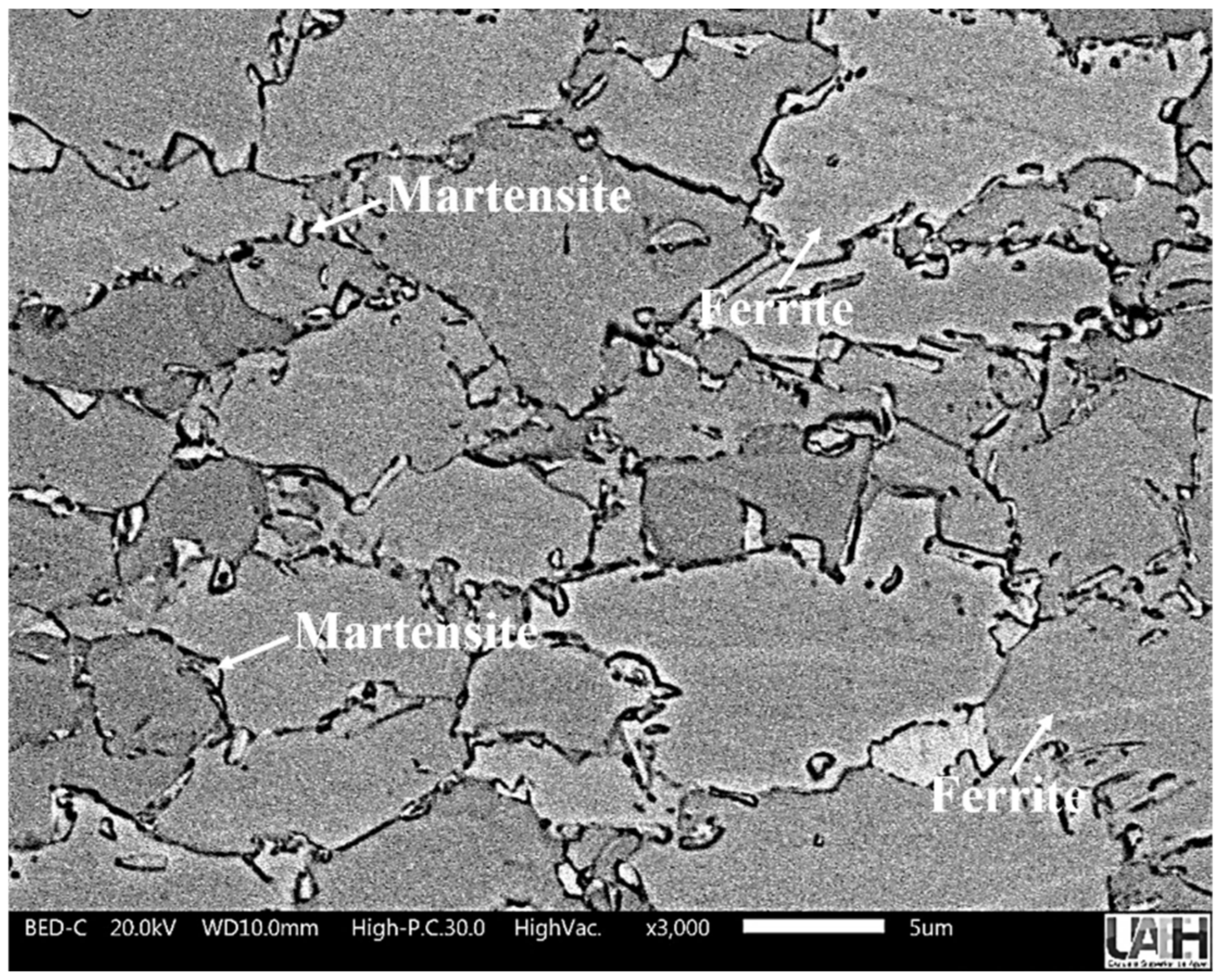
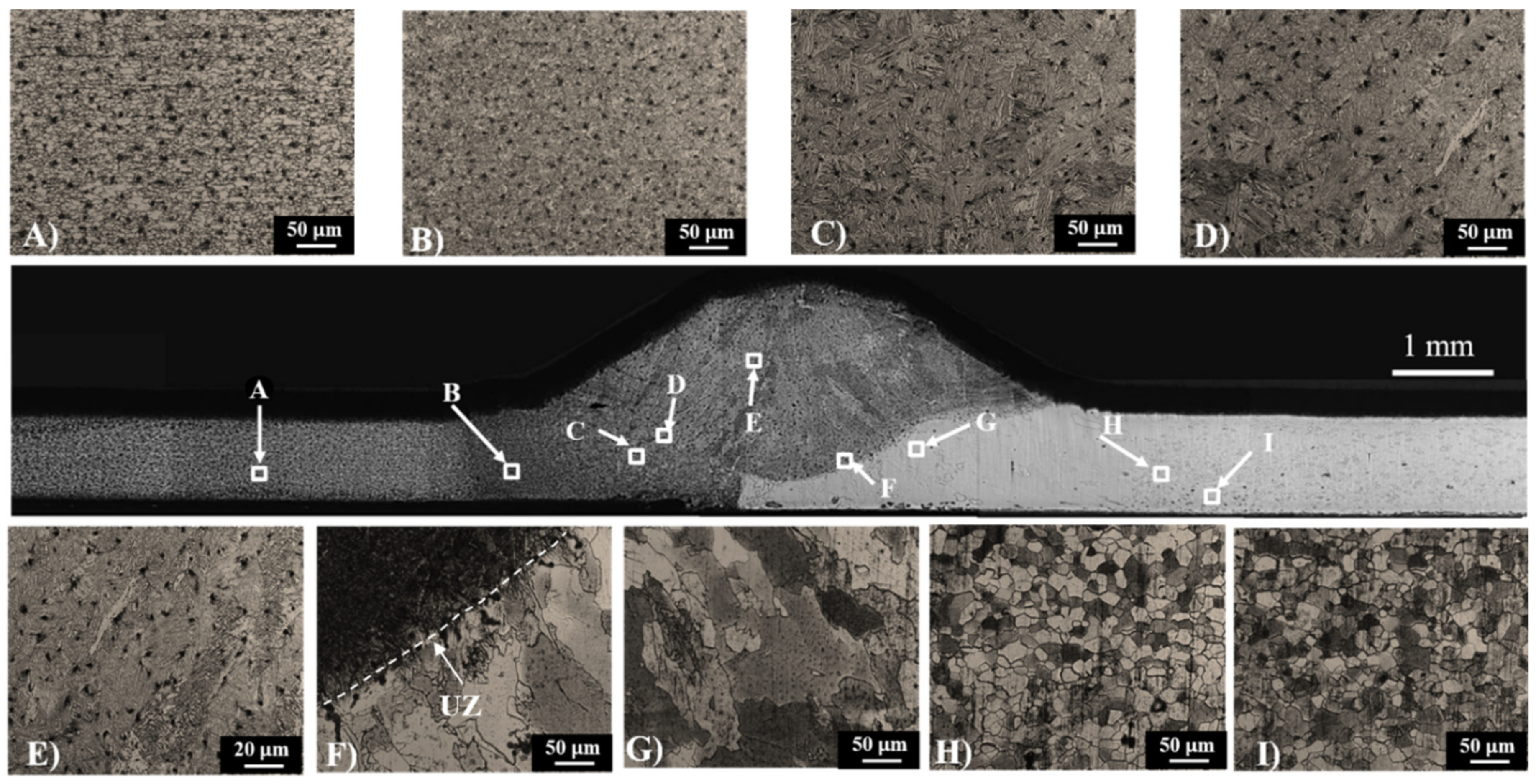
  • Dual phase–heat affect zone presented a grain growth and an increase of the martensite phase close to the welding bead, and then a grain refinement zone, while the grain growth and perlite phases incremented in the low carbon heat affected zone.
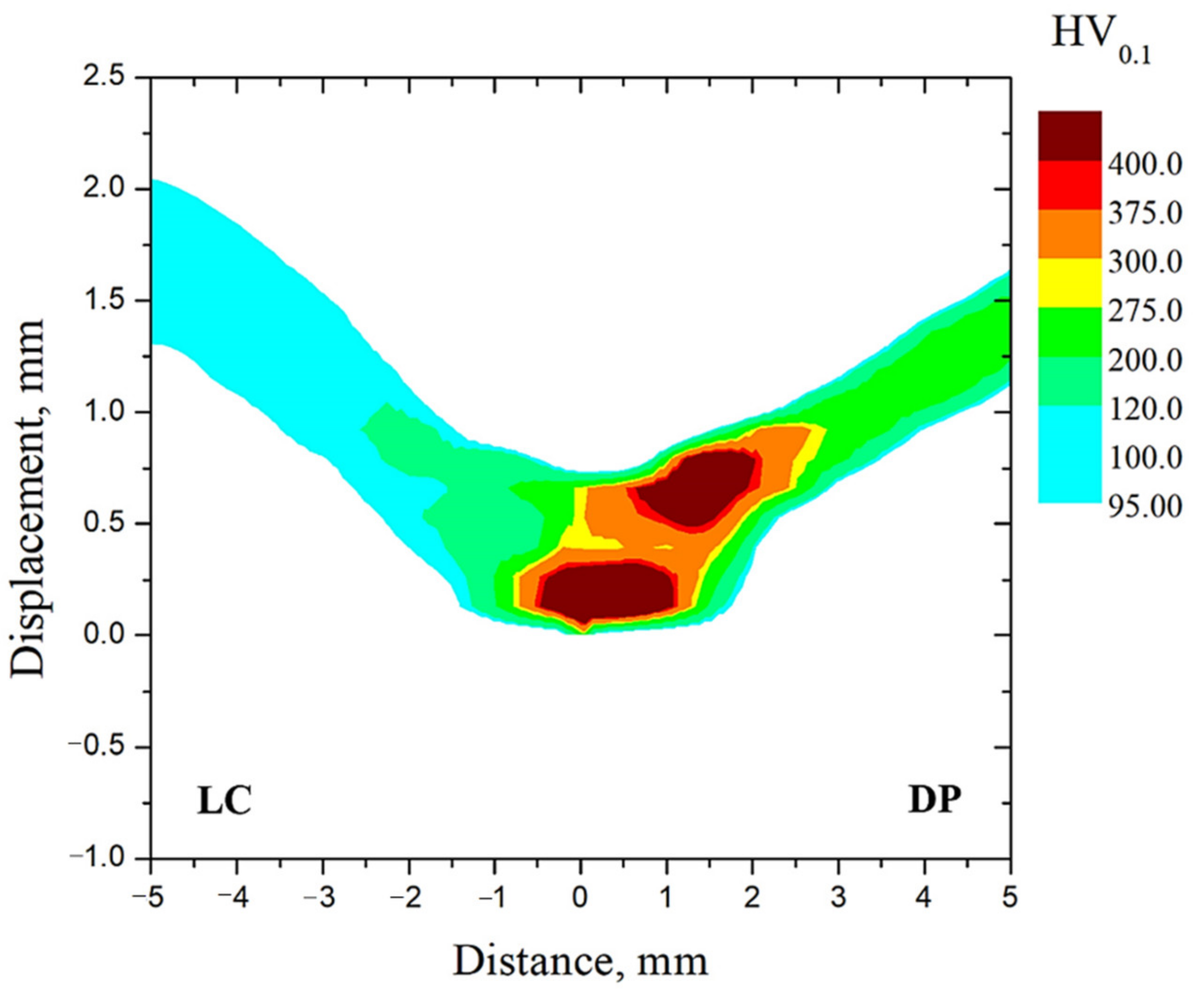
  • Microhardness profile showed the largest hardness in the welding bead and the dual phase–heat affect zone due to the presence of the martensite phase. The size of the heat affect zone was 3.8 and 1.8 mm for dual phase and low carbon steel, respectively. The end of the microstructural changes in the dual phase–heat affect zone was measured at approximately 242 °C. It was not detected a subcritical zone by means of this test.
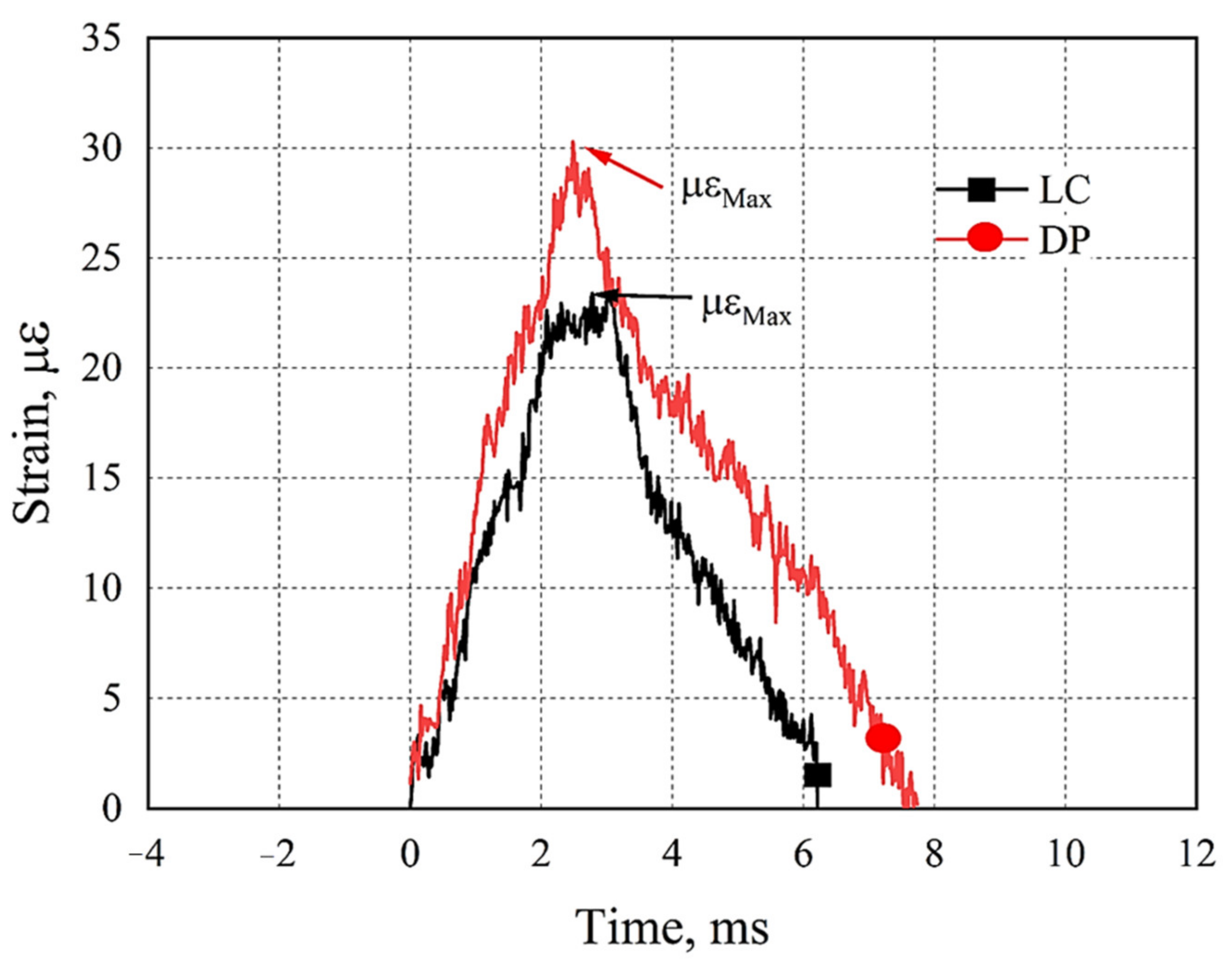
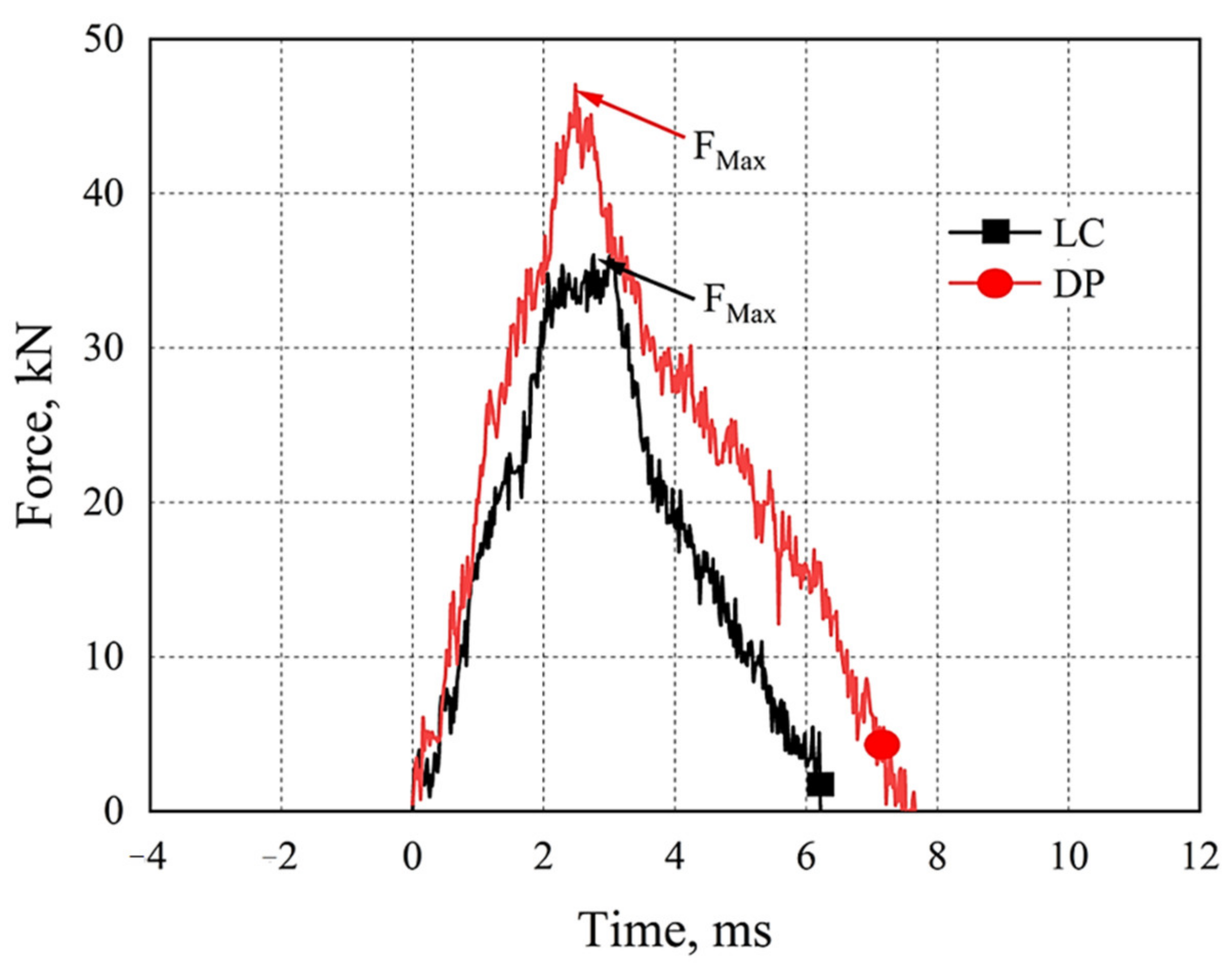
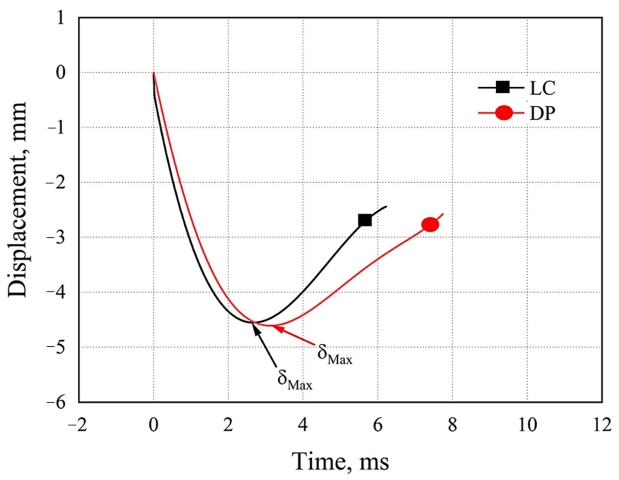
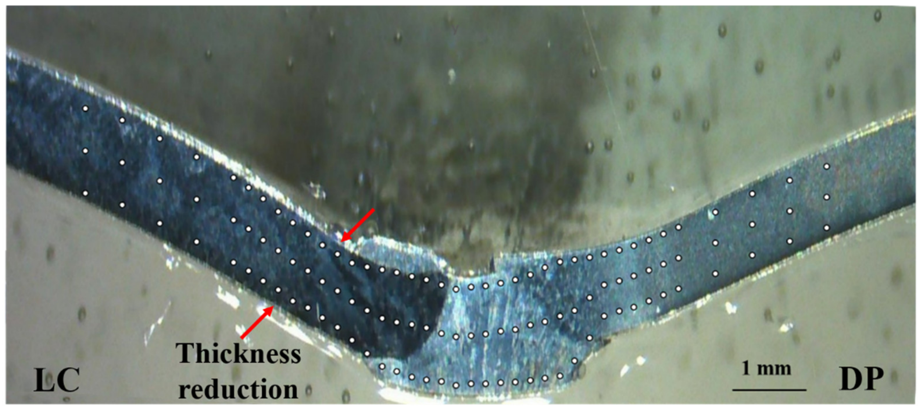
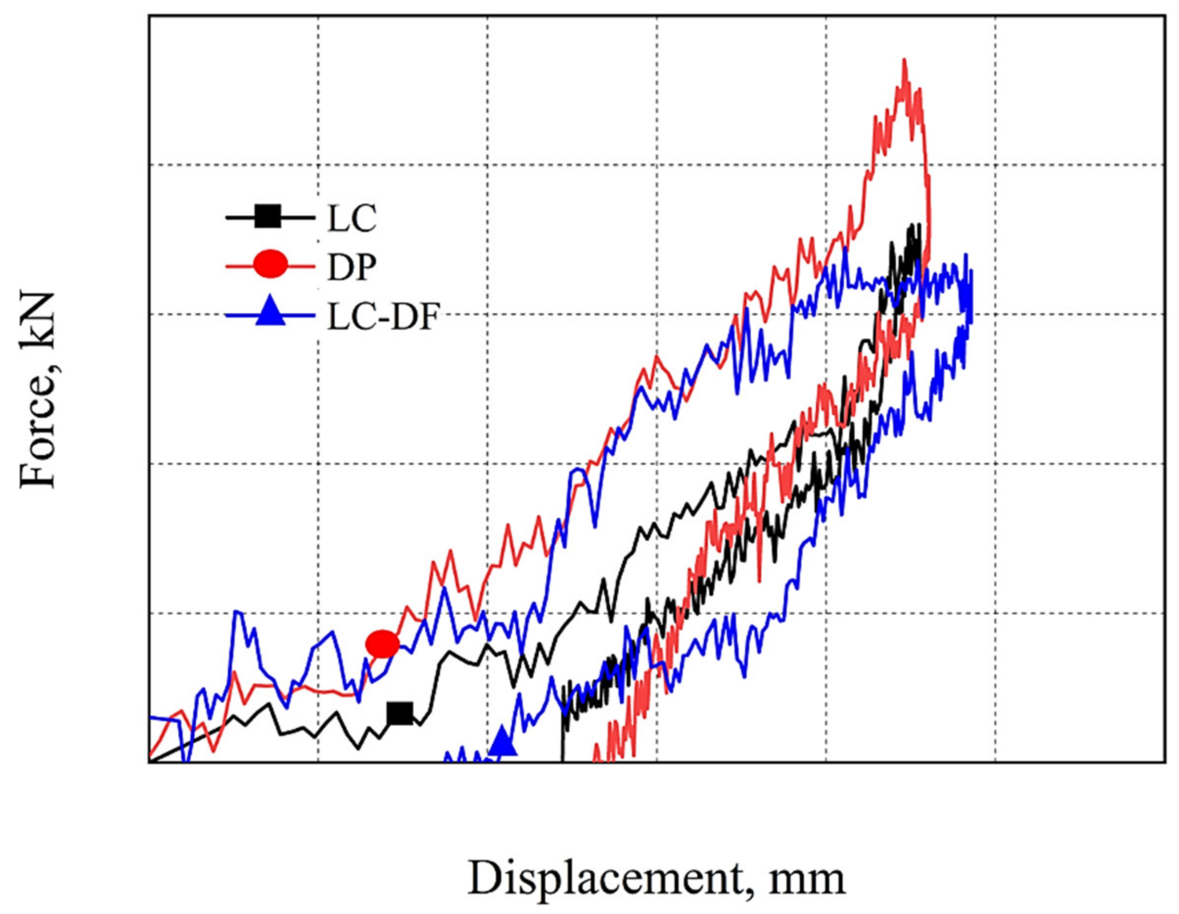
  • During the impact test, a thickness reduction in the low carbon heat affect zone was generated; however, the dissimilar welding was not fractured. The absorbed energy was 19.3 J for the low carbon steel, while for the dissimilar joint, it was (50.2 J), slightly lower than for DP steel (50.7 J). Nevertheless, it presents a better performance than LC steel.
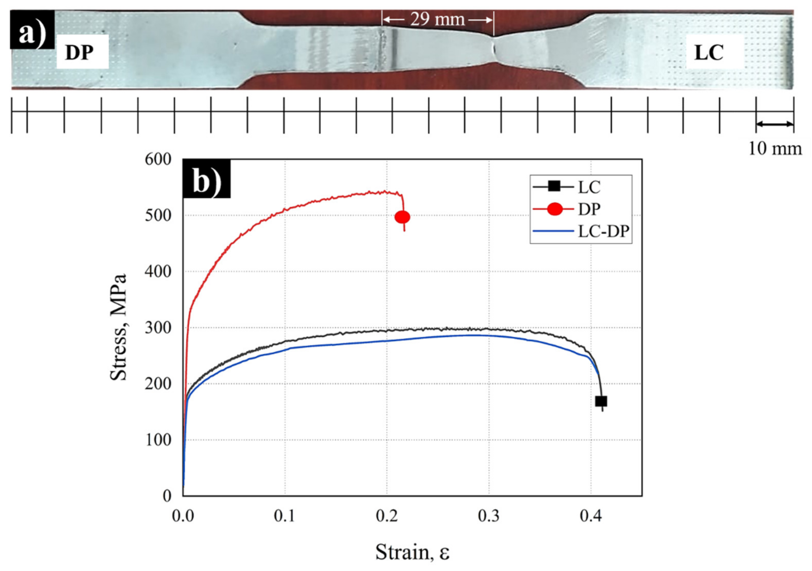
  • Dissimilar welding tensile strength was 172.89 MPa, similar to the low carbon steel which was 178.22 MPa. The tensile fracture zone was presented outside of the low carbon heat affect zone, at 29 mm from the welding bead, which suggests that an acceptable dissimilar joint was obtained.

Author Contributions

Conceptualization, C.M.G. and I.R.-L.; methodology, C.M.G. and I.R.-L.; software, C.M.G. and R.R.A.; validation, C.M.G., R.R.A., C.J.G. and D.J.; writing—original draft preparation, C.M.G.; writing—review and editing, R.R.A. and C.J.G.; funding acquisition C.M.G. All authors have read and agreed to the published version of the manuscript.

Funding

This research was funded by PRODEP (Project 219093).

Institutional Review Board Statement

Not applicable.

Informed Consent Statement

Not applicable.

Data Availability Statement

The data presented can be available upon request to corresponding author.

Acknowledgments

The authors thank to PEMSA for provides the base materials. In addition, to the Universidad Autónoma del Estado de Hidalgo (UAEH) and Instituto Politécnico Nacional (IPN), for allowing this project to be carried out in their facilities.

Conflicts of Interest

The authors declare no conflict of interest.

References

  1. Maurya, A.K.; Pandey, C.; Chhibber, R. Dissimilar welding of duplex stainless steel with Ni alloys: A review. Int. J. Press. Vessel. Pip. 2021, 192, 104439. [Google Scholar] [CrossRef]
  2. Kumar, S.; Sirohi, S.; Vidyarthy, R.S.; Gupta, A.; Pandey, C. Role of the Ni-based filler composition on microstructure and mechanical behavior of the dissimilar welded joint of P22 and P91 steel. Int. J. Press. Vessel. Pip. 2021, 193, 104473. [Google Scholar] [CrossRef]
  3. Baeslack, W.A.; Lippold, J.C.; Savage, F. Unmixed zone formation in austenitic stainless steel weldments. Weld. Res. Suppl. 1979, 168–175. [Google Scholar]
  4. Sauraw, A.; Sharma, A.K.; Fydrych, D.; Sirohi, S.; Gupta, A.; Świerczyńska, A.; Pandey, C.; Rogalski, G. Study on microstructural characterization, mechanicalproperties and residual stress of GTAW dissimilar joints of P91 and P22 steels. Materials 2021, 14, 6591. [Google Scholar] [CrossRef] [PubMed]
  5. Fostein, N. Dual-phase steels. In Automotive Steels; Elsevier Ltd.: Amsterdam, The Netherlands, 2017; pp. 169–216. [Google Scholar]
  6. Hilditch, T.B.; Souza, T.D.; Hodgson, P.D. Properties and automotive applications of advanced high-strength steels (AHSS). In Welding and Joining of Advanced High Strength Steels (AHSS); Elsevier Ltd.: Amsterdam, The Netherlands, 2015; pp. 9–28. [Google Scholar] [CrossRef]
  7. Barajas, N.C.; García, A.M.; Camporredondo, J.E.; Guillén, F.E.; Castruita, L. Tendencia de los aceros y su aplicación en la industria automotriz. Cienc. Cierta 2016, 48, 12. [Google Scholar]
  8. Gould, J.E.; Khurana, S.P.; Li, T. Predictions of microstructures when welding automotive advanced high-strength steels. Weld. J. 2006, 85, 111–116. [Google Scholar]
  9. Oliver, S.; Jones, T.B.; Fourlaris, G. Dual phase versus TRIP strip steels: Microstructural changes as a consequence of quasi-static and dynamic tensile testing. Mater. Charact. 2007, 58, 390–400. [Google Scholar] [CrossRef]
  10. Delincé, M.; Bréchet, Y.; Embury, J.D.; Geers, M.G.D.; Jacques, P.J.; Pardoen, T. Structure–property optimization of ultrafine-grained dual-phase steels using a microstructure-based strain hardening model. Acta Mater. 2007, 55, 2337–2350. [Google Scholar] [CrossRef]
  11. Kumar, A.; Singh, S.B.; Ray, K.K. Influence of bainite/martensite-content on the tensile properties of low carbon dual-phase steels. Mater. Sci. Eng. A 2008, 474, 270–282. [Google Scholar] [CrossRef]
  12. Ahiale, G.K.; Oh, Y.-J. Microstructure and fatigue performance of butt-welded joints in advanced high-strength steels. Mater. Sci. Eng. A 2014, 597, 342–348. [Google Scholar] [CrossRef]
  13. Májlinger, K.; Kalácska, E.; Spena, P.R. Gas metal arc welding of dissimilar AHSS sheets. Mater. Des. 2016, 5, 615–621. [Google Scholar] [CrossRef]
  14. Ramazani, A.; Mukherjee, K.; Abdurakhmanov, A.; Prahl, U.; Schleser, M.; Reisgen, U.; Bleck, W. Micro–macro-characterisation and modelling of mechanical properties of gas metal arc welded (GMAW) DP600 steel. Mater. Sci. Eng. A 2014, 589, 1–14. [Google Scholar] [CrossRef]
  15. Svoboda, H.; Lorusso, H.N.; Burgueño, A. Welding of dual phase steel sheet: GMAW, PAW and RSW. Soldag. Insp. 2011, 16, 165–176. [Google Scholar] [CrossRef]
  16. Kapustka, N.; Conrardy, C.; Babu, S.S.; Albright, C. Effect of GMAW process and material conditions on DP 780 and TRIP 780 welds. Weld. J. 2008, 87, 135–148. [Google Scholar]
  17. Elek, P.M.; Jaramaz, S.S.; Micković, D.M.; Miloradović, N.M. Experimental and numerical investigation of perforation of thin steel plates by deformable steel penetrators. Thin-Walled Struct. 2016, 102, 58–67. [Google Scholar] [CrossRef]
  18. Zhang, J.; Lu, G.; Zhang, Y.; You, Z. A study on ballistic performance of origami sandwich panels. Int. J. Impact Eng. 2021, 156, 103925. [Google Scholar] [CrossRef]
  19. Easterling, K. Introduction to the Physical Metallurgy of Welding; Elsevier Ltd.: Amsterdam, The Netherlands, 1992; pp. 1–54. [Google Scholar]
  20. ASTM E8/E8M; Committee Test Methods for Tension Testing of Metallic Materials. ASTM International: West Conshohocken, PA, USA, 2016. [CrossRef]
  21. Ueda, M.; Uchino, K.; Kobayashi, A. Effects of carbon content on wear property in pearlitic steels. Wear 2002, 253, 107–113. [Google Scholar] [CrossRef]
  22. ASTM-E112; E4 Committee and Grain Size Measurements. Standard Test Methods for Determining Average Grain Size. ASTM International: West Conshohocken, PA, USA, 2013. [CrossRef]
  23. Krajewski, S.; Nowacki, J. Dual-phase steels microstructure and properties consideration based on artificial intelligence techniques. Arch. Civ. Mech. Eng. 2014, 14, 278–286. [Google Scholar] [CrossRef]
  24. Farabi, N.; Chen, D.L.; Zhou, Y. Fatigue properties of laser welded dual-phase steel joints. Procedia Eng. 2010, 2, 835–843. [Google Scholar] [CrossRef] [Green Version]
  25. Ahiale, G.K.; Oh, Y.-J.; Choi, W.-D.; Lee, K.-B.; Jung, J.-G.; Nam, S.W. Microstructure and fatigue resistance of high strength dual phase steel welded with gas metal arc welding and plasma arc welding processes. Met. Mater. Int. 2013, 19, 933–939. [Google Scholar] [CrossRef]
  26. Kuril, A.A.; Ram, G.D.J.; Bakshi, S.R. Microstructure and mechanical properties of keyhole plasma arc welded dual phase steel DP600. J. Mater. Process. Technol. 2019, 270, 28–36. [Google Scholar] [CrossRef]
  27. Ordoñez, J.H.; Ambriz, R.R.; García, C.; Plascencia, G.; Jaramillo, D. Overloading effect on the fatigue strength in resistance spot welding joints of a DP980 steel. Int. J. Fatigue 2019, 121, 163–171. [Google Scholar] [CrossRef]
  28. Sirohi, S.; Taraphdar, P.K.; Dak, G.; Pandey, C.; Sharma, S.K.; Goyal, A. Study on evaluation of through-thickness residual stresses and microstructure-mechanical property relation for dissimilar welded joint of modified 9Cr–1Mo and SS304H steel. Int. J. Press. Vessel. Pip. 2021, 194, 104557. [Google Scholar] [CrossRef]
  29. Romero-Nieto, S.P.; Olaya-Flórez, J.J. Influence of the transfer by arc on the microstructure of welded joint produced by pulsed arc. Ing. Mec. 2013, 16, 1–12. [Google Scholar]
  30. Reyes–Carcasés, D.; Fernández–Columbié, T.; Alcántara–Borges, D.; Rodríguez–González, I. Welding with coated electrodes E 6010 and E 7018 in AISI 1025 steel. Min. Geol. 2018, 34, 108–121. [Google Scholar]
  31. Corbett, G.G.; Reid, S.R.; Johnson, W. Impact loading of plates and shells by free-flying proyectiles: A review. Int. J. Impact Eng. 1996, 18, 141–230. [Google Scholar] [CrossRef]
  32. Field, J.E.; Walley, S.M.; Proud, W.G.; Goldrein, H.T.; Siviour, C.R. Review of experimental techniques for high rate deformation and shock studies. Int. J. Impact Eng. 2004, 30, 725–775. [Google Scholar] [CrossRef]
Figure 1. Welded joint preparation.
Metals 12 00404 g001
Figure 2. Thermocouples’ location for the experimental temperature measurements.
Metals 12 00404 g002
Figure 3. Welded joint and indentation line followed for the microhardness measurement.
Metals 12 00404 g003
Figure 4. Experimental arrangement of the free–fall impact test.
Metals 12 00404 g004
Figure 5. Grain size determination (a,b) traces of different phases of LC and DP steel with AutoCAD software; (c) perlite count of LC steel and (d) ferrite count of DP steel.
Metals 12 00404 g005
Figure 6. LC steel microstructure obtained by means of SEM.
Metals 12 00404 g006
Figure 7. DP steel microstructure obtained by means of SEM.
Metals 12 00404 g007
Figure 8. Strain–time behavior of LC and DP steel.
Metals 12 00404 g008
Figure 9. Force–time behavior of LC and DP steel.
Metals 12 00404 g009
Figure 10. Displacement during the impact test on LC and DP steel.
Metals 12 00404 g010
Figure 11. Experimental weld thermal cycles for DP steel.
Metals 12 00404 g011
Figure 12. Dissimilar weld of LC and DP steels: (a) Top view and (b) transversal section showing different welding zones. FZ–fusion zone, GGZ–grain growth zone, GRZ–grain refinement zone, TBMZ–tempering base metal zone, and BM–base metal.
Metals 12 00404 g012
Figure 13. Microstructural changes generated by the welding process in dissimilar weld LC–DP: (A) TBMZ; (B) GRZ; (C) DP GGZ; (D) DP GGZ–FZ interface; (E) FZ; (F) LC GGZ–FZ interface; (G) LC GGZ; (H,I) LC BM.
Metals 12 00404 g013
Figure 14. Microhardness profile of dissimilar welding LC–DP steels.
Metals 12 00404 g014
Figure 15. (a) Tensile fracture in the LC–DP dissimilar welding and (b) stress-strain behavior for the base metals and the LC–DP dissimilar welding.
Metals 12 00404 g015
Figure 16. Front view of the dissimilar welding after impact test.
Metals 12 00404 g016
Figure 17. Hardness distribution after impact test in dissimilar welding LC–DP.
Metals 12 00404 g017
Figure 18. Strain vs. time and force vs. time behavior of dissimilar welding during the impact test.
Metals 12 00404 g018
Figure 19. Displacement during the impact test on LC–DP welding.
Metals 12 00404 g019
Figure 20. Force–displacement assessment during the impact test on LC, DP, and LC–DP welding.
Metals 12 00404 g020
Table 1. Chemical composition of DP, LC steel and ER70S-6 filler metal (wt. %).
MaterialCMoCuAlMnPCrCoSNiSiFe
* DP0.1040.00130.0220.792.00.0170.020.00380.0130.020.422Bal.
* LC0.0350.0150.0190.0390.0870.0130.025<0.0040.00650.018<0.011Bal.
** ER70S-60.080.0020.1201.450.008000.0110.0130.84Bal.
* Chemical composition obtained by means of optical spectrometry. ** Nominal chemical composition.
Table 2. Phases percentage in LC and DP steel.
SteelPhaseAverage Grain Size (µm2)Percentage (%)
LCFerrite168.648.79
Perlite228.051.21
DPFerrite2180.76
Martensite1.15619.24
Table 3. Tensile mechanical properties of the base materials and LC–DP dissimilar welding.
Materialσy, MPaσmax, MPaεmax, %H, MPan
LC178.22300.3841.0368.320.135
DP320.51543.7321.6724.680.161
LC-DP172.89286.5841.0355.60.129
Publisher’s Note: MDPI stays neutral with regard to jurisdictional claims in published maps and institutional affiliations.

