Abstract
Joints of complex phase 780 (CP-780) advanced high strength steel (AHSS) were carried out by using an ER-CuAl-A2 filler metal for the gas metal arc welding pulsed brazing (GMAW-P- brazing) process and the ER-80S-D2 for the GMAW-P process employing two levels of heat input. The phases in the weld bead and HAZ were analyzed, and the evaporation of zinc by means of scanning electron microscopy (SEM) was also monitored. The mechanical properties of the welded joints were evaluated by tension, microhardness and vertical impact tests. It was found that there was greater surface Zn evaporation in the joints welded with the GMAW-P process as compared to the GMAW-P-brazing process. The best results in tensile strength were observed in the joints welded with GMAW-P-brazing process, which increased by ~68% with respect to those of the GMAW-P. This behavior can be attributed to the formation of an intermetallic complex compound Cu-Al-Fe in the fusion line.
1. Introduction
Nowadays, automobile manufacturers are intensively seeking to improve vehicle efficiency, aiming to minimize CO2 emissions and reduce fuel consumption [1]. These benefits have both financial and environmental impacts, affecting the design of vehicles as it is dictated, to a large extent, by the selection of the material for its manufacture [2]. Achieving these goals requires a combination of high-tech materials, innovative designs, advanced manufacturing processes and good design along with proper welding processes and welding procedures [3]. AHSSs possess a broad spectrum of properties, depending on their structure and grades, such as complex phase (CP), dual phase (DP), transformed induced plasticity (TRIP) and twinning-induced plasticity (TWIP), among others. All of them offer remarkable properties such as strength, formability, weldability, durability and impact resistance as compared to high strength steels (HSSs), making them very attractive for the automotive sector [4]. A total of 12% are used commercially in the vehicle bodywork; 47% include high-strength steels (HSSs), which were previously applied, and the remaining 41% are mild steels [5]. Usually, components made with AHSS require processing by joining methods for their final assembly. For this, fusion welding processes such as GMAW and GTAW have been mainly used; however, in the last ten years, new welding technologies such as laser, electron beam, plasma welding and GMAW-P have been developed. The GMAW pulsed arc process has received more attention in virtue of its benefits and it has led to a number of developments in techniques such as cold metal transfer (CMT), surface tension transfer (STT) [6], super pulse [7] and other variants [8].
GMAW brazing has been used in short circuit transfer mode due to the low heat input during fusion as compared with spray and globular transfer modes. The automotive industry has focused especially on solving burn-off coated AHSS materials [9]. However, due to the better arc control of pulsed arc, GMAW-P has received more attention in virtue of its benefits [10].
The GMAW welding process used with the pulsed transfer mode along with brazing welding has a mechanism that allows depositing metal with a low heat input, due to the low melting points of the brazing electrodes. These features satisfy adequate conditions for welding coated AHSS. Additionally, by using electrodes with a low melting point, such as the ERCuAl-2 electrode, the probability of microstructural transformations occurring in these steels is further reduced.
There are several problems that may arise during fusion welding of coated AHSS. Shome et al. carried out MIG-Brazing welding of a DP-590 steel with a CuAl8 filler metal, observing that the intensity of the brazing heat is directly related to the welding current and it is critical to determine the degree of zinc evaporation [11]. Berczeli et al. studied the mechanical behavior of dissimilar welds between a zinc-coated DP 600 steel and DC 01 steel, with a CuSi3 electrode. The authors found that there is a maximum in the hardness profile at the edge of the DP-600 steel and the CuSi3 welding material [12]. Singh et al. evaluated the CMT welding process for lap joining of zinc-coated DP-780 steel with a CuAl10Fe filler wire and observed that the heat input increased the concentration of intermetallic compounds from 13.9% to 15.6% [13]. Varol et al. analyzed the evaporation of zinc for a TRIP-800 steel with a CuAl8 filler metal; a low heat input was seen to decrease the evaporation of zinc from the joint of the galvanized steel [14].
The objective of this study was to perform welded joints of the AHSS CP-780 by using conventional GMAW-P and GMAW-P-brazing in order to establish a comparative analysis of the two welding techniques using two different heat inputs. Hence, the effect of the heat input on the microstructural behavior of the welding interface and the heat affected zone (ZAT) were studied. Furthermore, mechanical resistance with microhardness, tensile and free fall tests were conducted to evaluate the quality of the welds.
2. Materials and Methods
For this investigation, hot rolled sheets of 200 mm × 70 mm × 2.5 mm CP-780 steel (780 MPa in ultimate tensile strength) were lap prepared for welding with the GMAW-pulsed process. The ER 80S-D2 and ER CuAl-2 filler wires were used for welding with an 80%Ar-20%CO2 gas mixture and with 100% Ar, respectively. The chemical composition of the base metal (BM) and filler wires is listed in Table 1.

Table 1.
Chemical composition of the CP-780 sheets and electrodes, (wt.%).
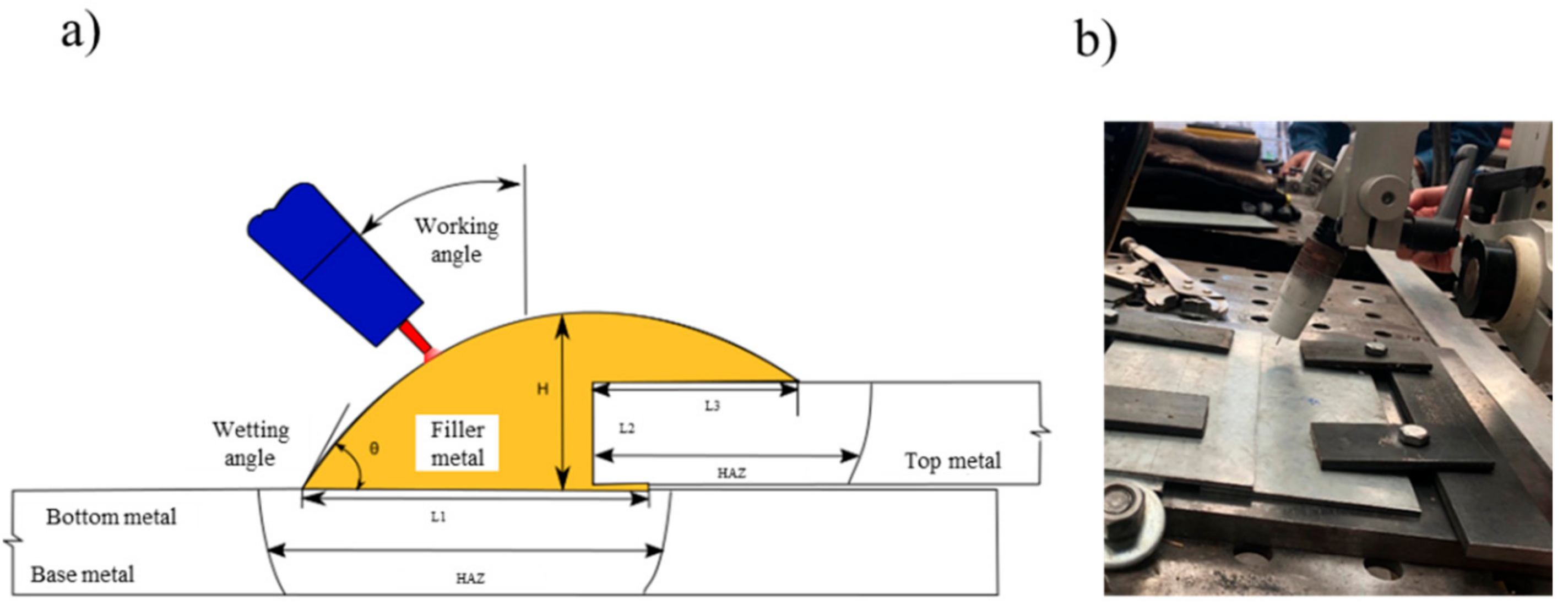
The sheets were lap welded in flat position and the torch was tilted 20° with reference to the normal to perform the fillet weld during the application of the filler as illustrated in Figure 1. Prior to welding, all the samples were thoroughly degreased with acetone at the edge to be joined; the welding parameters according to the experiments are displayed in Table 2. In this study, two different heat inputs were assessed for both GMAW methods, pulsed and pulsed-brazing; low and high heat input designated as condition C1 and condition C2, respectively.

Figure 1.
(a) Schematic of the lap welded joint and (b) fixture holding the sheets and torch angle.
Table 2.
Welding parameters.
2.1. Microstructural Characterization
For microstructural characterization of the BM, a piece of CP 780 was cut and machined in transverse direction in a rectangular shape. The metallographic preparation was carried out in 3 stages: (I) mechanical grinding with abrasive silicon carbide paper of different grits, (II) mirror polishing of specimens using 5 and 1 µm Al2O3, and (III) chemical etching by immersion with 5% nital for 8 s according to ASTM 407-07 standard [15].
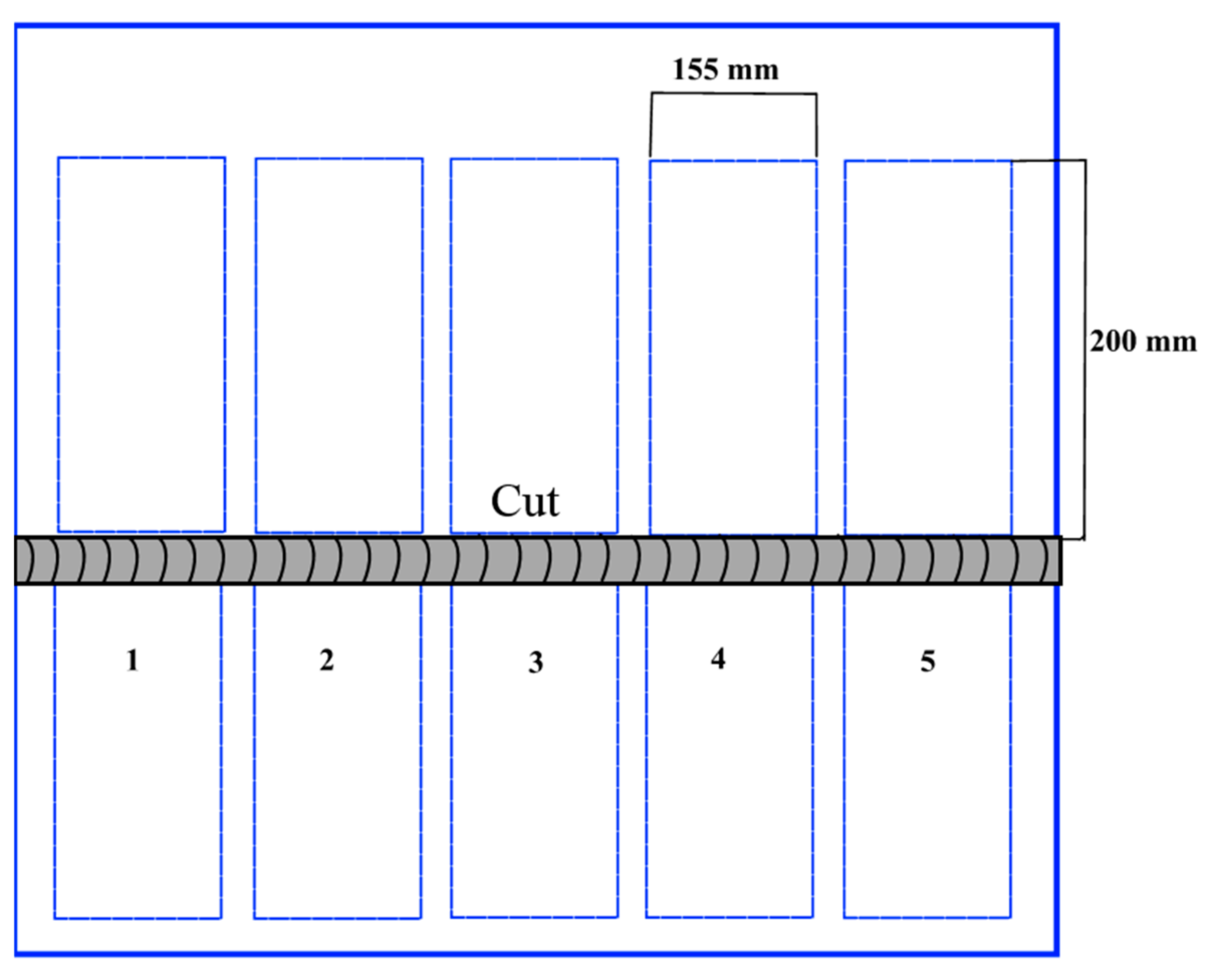
The welded joints were sectioned as schematically shown in Figure 2 for different evaluations. A sample of each welding condition was cut for metallographic analysis; the procedure previously described was employed, but for the ERCuAl-2 electrode, the etching solution containing 1.25 g FeCl3, 7.5 mL HCl and 25 mL methanol (CH3OH) was used.
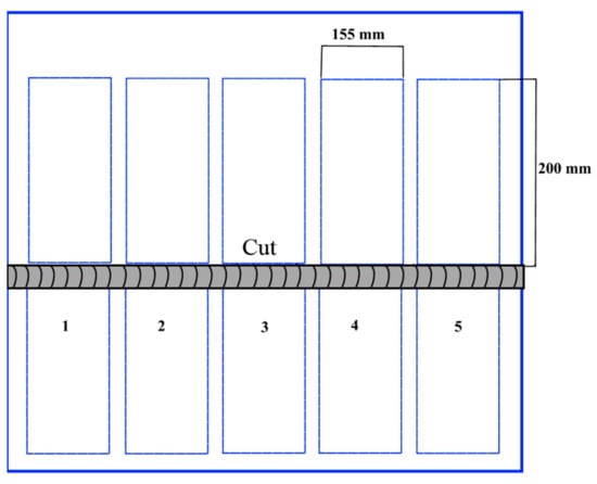
Figure 2.
Schematic of the cuts performed in the lap welded joints for characterization.
Subsequently, microstructural observation was carried out by optical microscopy (OM, Carl Zeiss, Oberkochen, Germany) and scanning electron microscope (SEM, JEOL, Tokyo, Japan) JEOL JSM-7600F equipped with an energy dispersive X-ray spectroscopy (EDS) analyzer (XFlash Detector 6|10, Bruker AXS GmbH, Berlin, Germany).
2.2. Mechanical Evaluation
For the mechanical behavior, microhardness and tension tests were performed in both, the BM and the lap welded joints in the C1 and C2 conditions. Vickers microhardness profiles were performed according to the ASTM E384-17 standard [16] with a Mitutoyo HM 210 microhardness tester (Mitutoyo, Yehan Numata, Japan); for all the specimens, a load of 0.1 kg was applied during 15 s. Preparation of the specimens was carried out for the metallographic characterization. The microhardness profiles were made in 3 zones: the first was in the BM with a distance of 0.300 mm between measurements, the second was in the HAZ with a distance of 0.150 mm between measurements, and the third was in the weld bead with a distance of 0.100 mm between measurements. A schematic of the trajectory followed by the microhardness measurements in the different lap welded joints is presented later on, along with the microhardness plots.
Tension tests were performed in the BM as described in the ASTM E8 standard for determining the ultimate tensile strength, yield stress and elongation. For the weldment evaluation, samples of 12 mm width were cut from the lap welded joints. Due to the complex geometry of the samples, only the force to failure and length were determined from these tests.
2.3. Free Fall Impact Tests
For the vertical impact test, welded samples of 16 cm × 20 cm were tested under a free fall tower by hitting the welded joints with a projectile with a constant load according to the ASTM E208 standard [17]. The potential energy, kinetic energy and impact velocity were calculated for the analysis of the free fall impact test by the equations [18]:
where
- m is the mass applied during the test (kg).
- g is the gravitational constant.
- h is the height where the mass was free leaving.
- v is the velocity of the mass reached during the test.
The height of the 29.4 kg mass was free falling in the tower from 1.4 m and the potential and kinetic energies were 300 J and 403.6 J, respectively, at an impact velocity of 5.24 m/s. During the tests, data were gathered in order to determine the force during the impact and the deformation in the weldments.
3. Results and Discussion
3.1. Microstructural Characterization of Base Metal
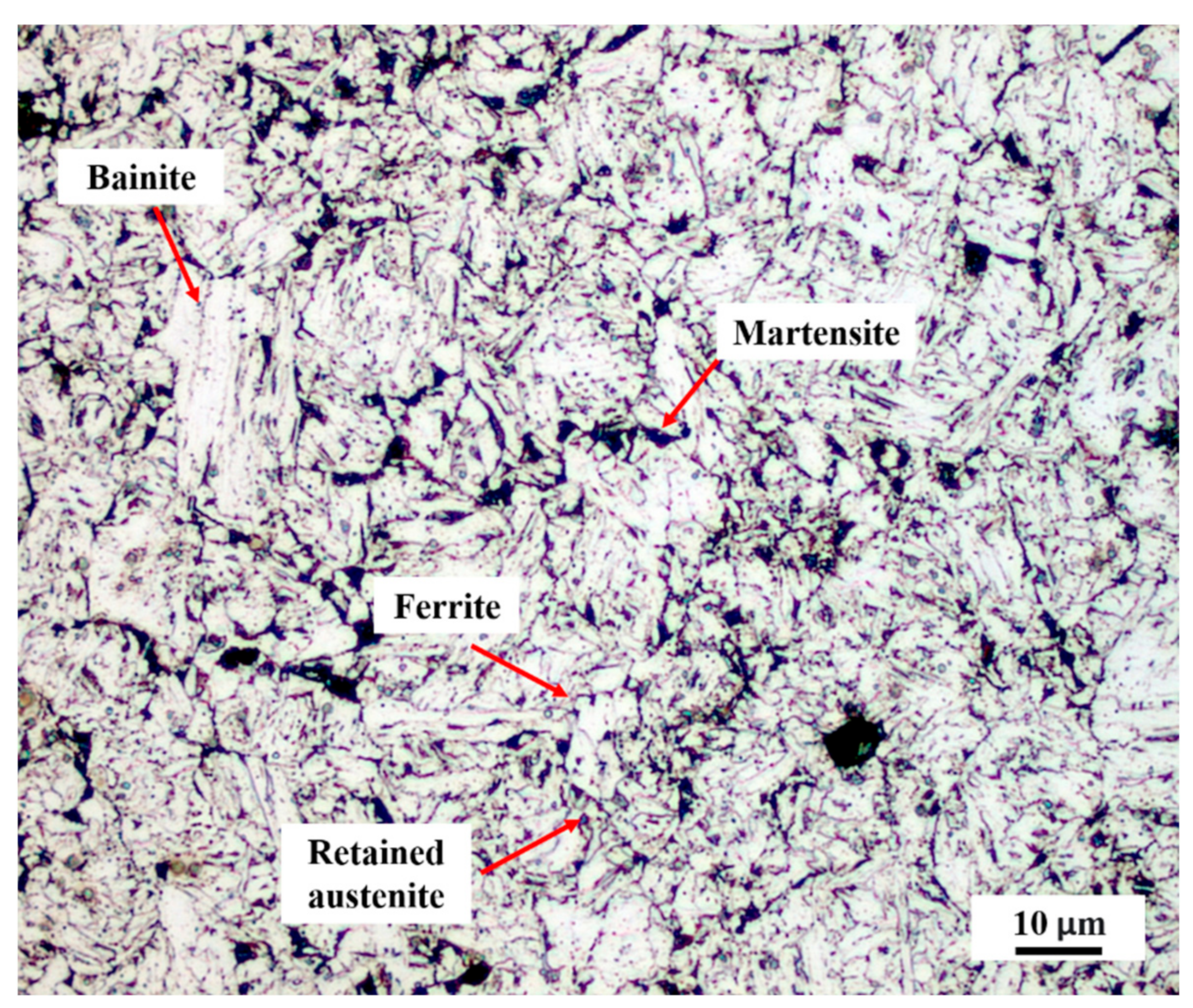
Figure 3 shows the micrographs of the CP 780 BM in the as-received condition, as observed in the OM in the transverse section. An average grain size of 2 μm was determined according to the ASTM E-112 standard [19]. Uniform and refined grains were observed due to the recrystallization that took place in the thermomechanical process for the manufacture of the complex-phase steel. The microstructure is composed of phases such as ferrite, bainite, martensite islands and retained austenite. The thermomechanical process for CP steels is fundamental, since among its benefits is forming the different phases that compose its characteristic microstructure and lead to extensive grain refinement. The grains were refined through repeated recrystallization cycles in the thermomechanical process [20]. The content of each phase was determined according to ASTM E 562-02 [21] and correspond to 53% bainite, 25% martensite, 20% ferrite and 2% retained austenite. CP steels are characterized by having a bainitic matrix with martensite, ferrite, retained austenite phases and also precipitates (carbides or carbonitrides) at the nanoscale levels [22].
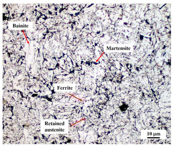
Figure 3.
Microstructure of the BM CP 780.
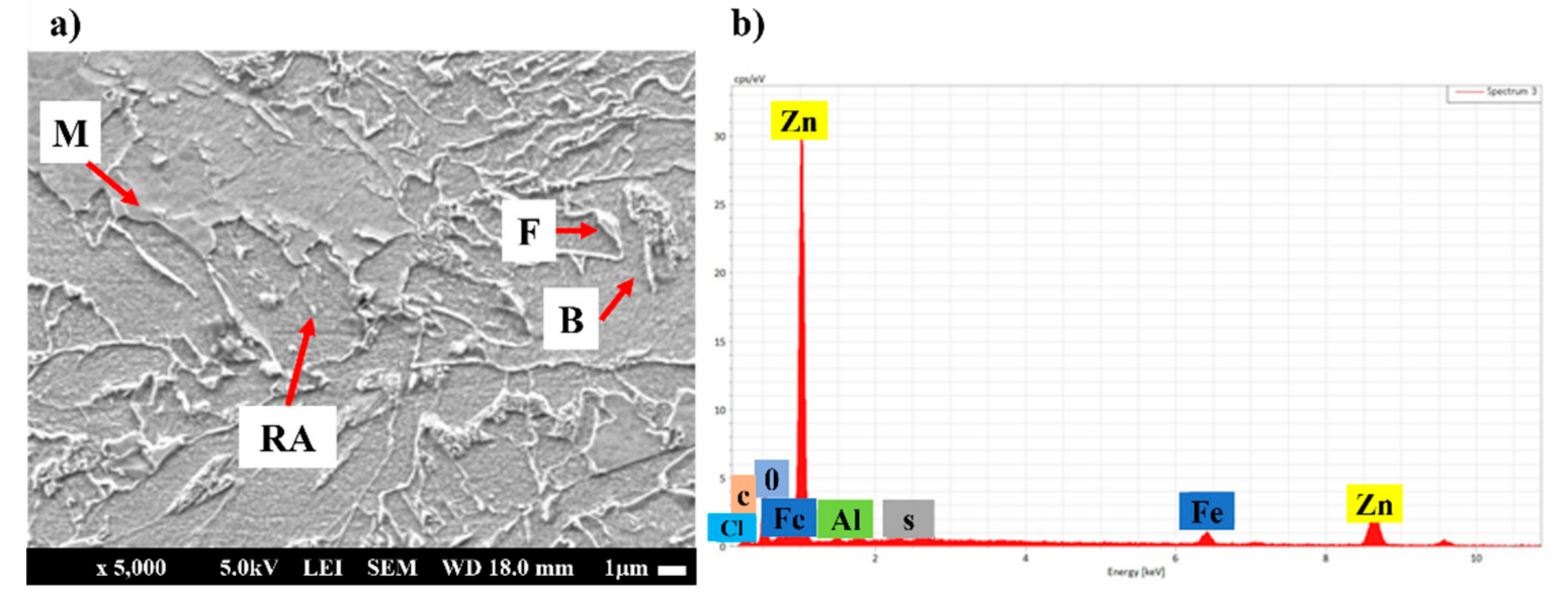
Figure 4 shows the microstructure of the CP 780 steel as observed in the SEM. Figure 4a shows the presence of bainite (B), martensite (MA), ferrite (F) and retained austenite (RA) as indicated by the arrows in the micrographs [23]. On the other hand, Figure 4b shows the EDS spectrum of the evaluation of Zn on the surface, where Zn is mainly detected along with Fe, C and Al. The presence of Zn is due to the galvanizing process of the steel.
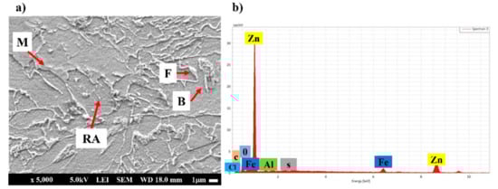
Figure 4.
SEM observation. (a) microstructure of the BM and (b) EDS analysis.
De Bruycker et al. [24] determined the concentration of Zn and other elements that are used during the galvanizing process of a CP 1000 steel. Among the most important elements that help to protect against corrosion is chromium, (3 wt.% or higher) and Zn (22 wt.%), depending on the chemical composition of the steel. The thickness of Zn is very thin in the range of 5 to 25 µm, on the surface of the steel.
3.2. Microstructural Characterization of Lap Weldments
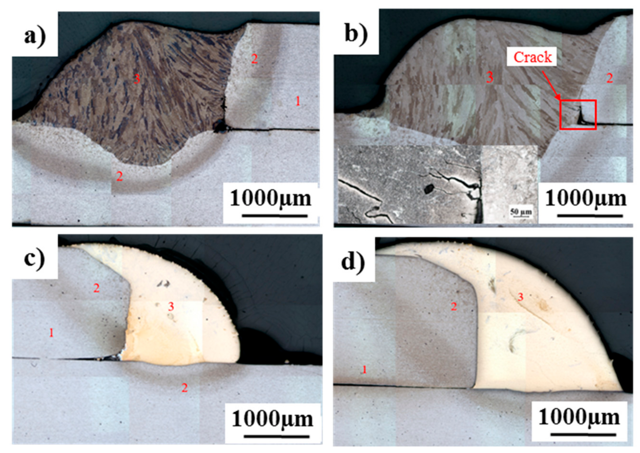
Figure 5 shows a comparative analysis of the macrostructural features of the weldments for GMAW-P and GAMW-P-brazing processes. Region (1) corresponds to the base metal CP 780 steel, region (2) shows the HAZ and region (3) is the filler metal. Figure 5a shows condition 1 (C1-low heat input), where lack of fusion between both plates and small cracks between the fusion zone and the HAZ are observed. The dimension of the HAZ of the upper plate with the weld bead measures 0.15 ± 0.02 mm and that of the lower plate with respect to the weld bead is 0.072 ± 0.01 mm. Figure 5b represents condition 2 (C2-high heat input), where the lack of fusion between both plates and cracks near the fusion zone are observed too; the dimension of the HAZ of the upper plate with the weld bead measures 0.163 ± 0.02 mm and of the bottom plate with respect to the weld bead is 0.085 ± 0.01 mm. The size of the HAZ is greater in condition 2 than in condition 1; this is due to the difference in the heat input. Figure 5c,d show the macrograph of condition 1B (C1-Brazing) and condition 2B (C2-Brazing) with low and high heat input, respectively, where complete fusion is observed for both conditions. In C1-B, the HAZ with respect to the upper sheet with the weld bead was 0.126 ± 0.02 mm and to the lower sheet, 0.042 ± 0.01 mm. In C2-B, the dimension of the HAZ was 0.136 ± 0.02 mm from the upper sheet and 0.054 mm from the lower sheet with respect to the weld bead.
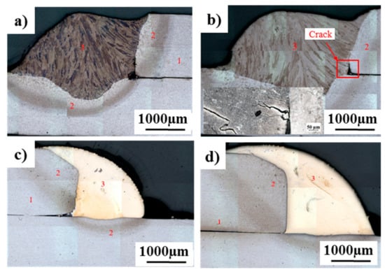
Figure 5.
Macrostructural sections of welds. (a) GMAW-P low heat input, (b) GMAW-P high heat input, (c) GMAW-P-brazing low heat input and (d) GMAW-P-brazing high heat input.
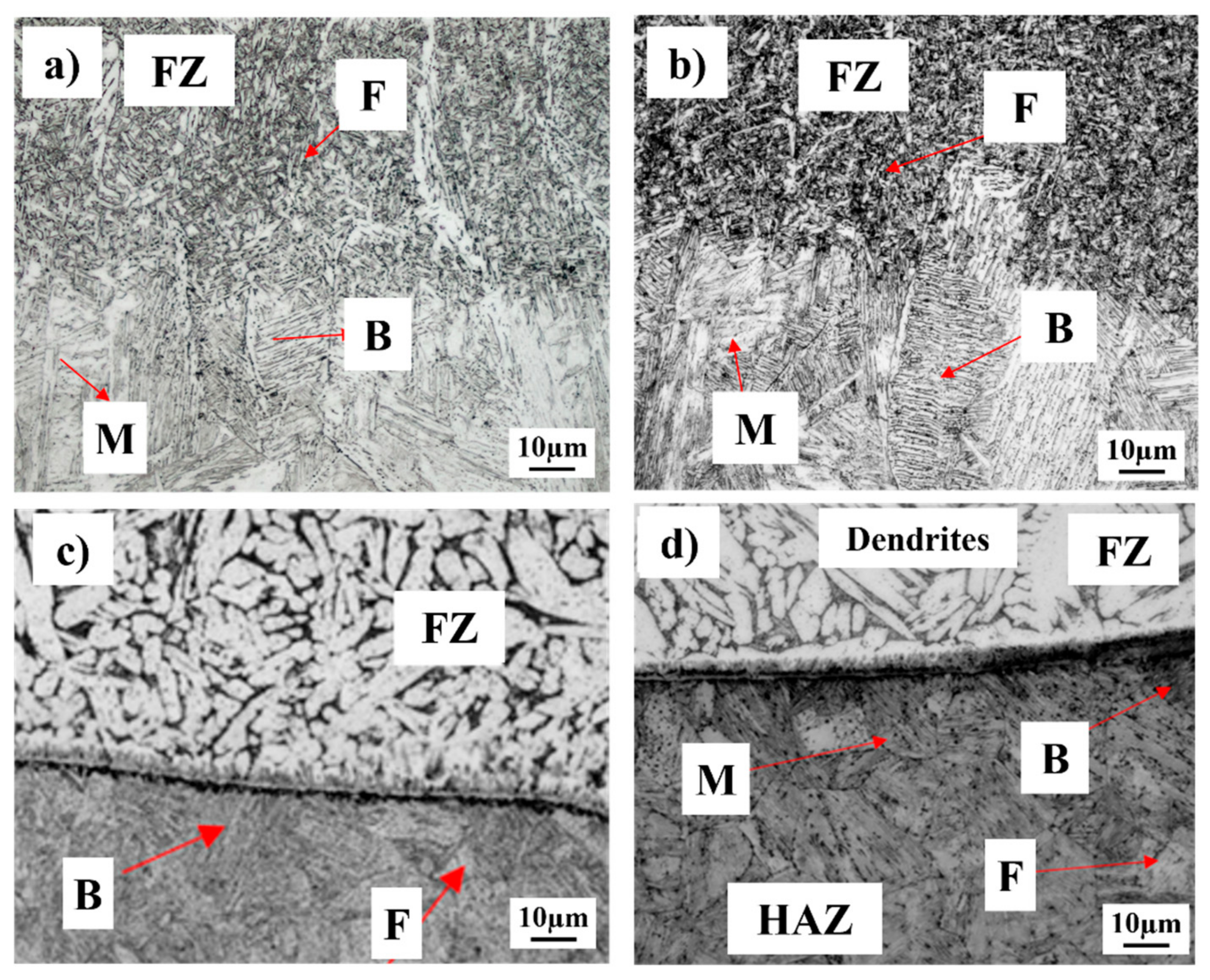
Figure 6 shows the microstructural characteristics of the ER80S and brazing electrode with low and high heat input. In Figure 6a, with low heat input, the fusion zone (FZ) shows columnar growth and in the HAZ, two types of grain zones may be observed, fine grain and coarse grain. An acicular ferrite (F) transformation is observed and in the HAZ, a mixture of lath-type martensite (M) and upper bainite (B) phases is observed. Meanwhile, with high heat input, in Figure 6b the fusion zone presents an acicular ferrite structure and the HAZ exhibits a bainitic and completely martensite structure; this produced hot cracking due to the high thermal input. Similarly, in the HAZ, a mixture of martensite and bainite phases is observed.
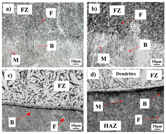
Figure 6.
Microstructural features of the GMA welds: (a) ER80S low heat input, (b) ER80S high heat input, (c) brazing low heat input and (d) brazing high heat input.
Additionally, in Figure 6c,d Cu-rich dendritic growth of the filler metal is observed and there is an interface of an intermetallic compound between the fusion zone (FZ) and the HAZ of approximately 3 to 8 μm. The intermetallic compound grew with the increase in deposited metal and heat input. In the HAZ, a lath-type martensitic transformation is observed, with upper bainite and a low percentage of ferrite; the grain size at the interface did not undergo coalescence and did not grow either, as occurred in the fusion process. This was due to the low energy necessary to melt the filler metal. The phase transformations in the HAZ are owing to the GMAW-P-brazing process, which reaches a maximum temperature of 850 °C. The ERCuAl-A2 electrode used in the current study produces a cooling rate in the range of 35–120 °C/s; by virtue of this, the transformation of phases found in the HAZ takes place [13,14,25].
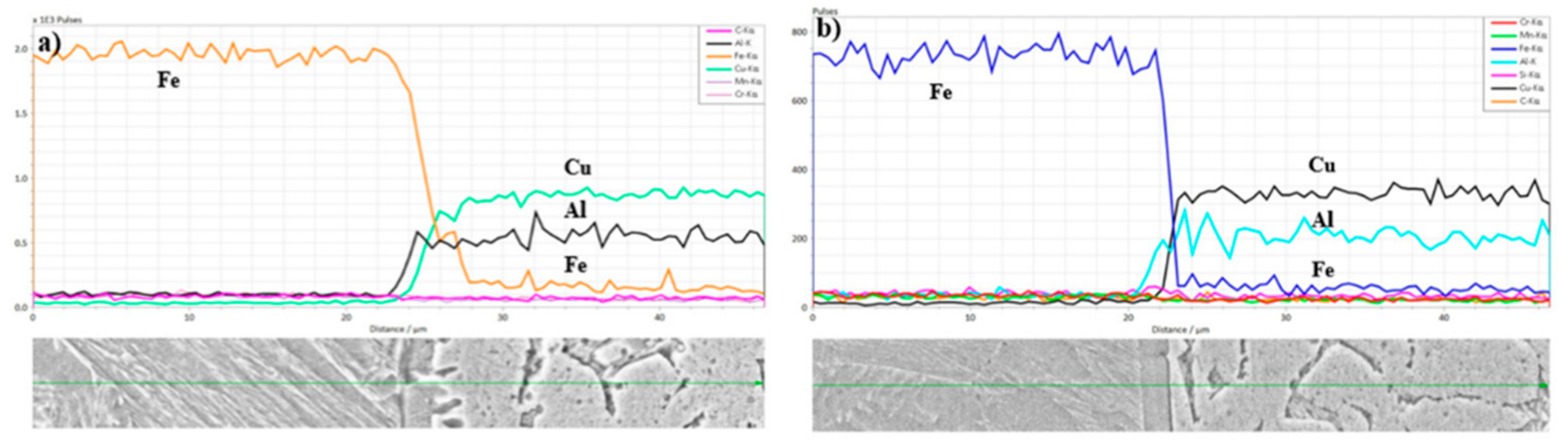
Figure 7 shows line scan of the chemical composition performed at the interface of brazing welds by means of SEM-EDS, where the main elements analyzed are Fe, Cu and Al. In both cases it can be seen that the molten zone is rich in Cu, Al and Fe, which corresponds to the elements of the filler metal used. On the other hand, the chemical content of Fe decreases in the interface from the CP steel to the weld metal. The content of Cu and Al increases as the profile was measured in the FZ indicating the chemical composition of the weldments.
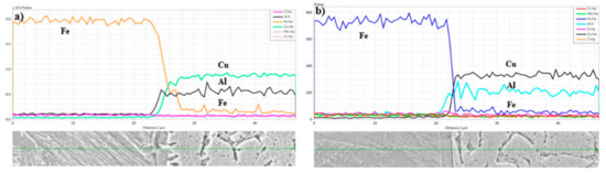
Figure 7.
Line scan in GMA welds: (a) brazing low heat input and (b) brazing high heat input.
3.3. Mechanical Testing
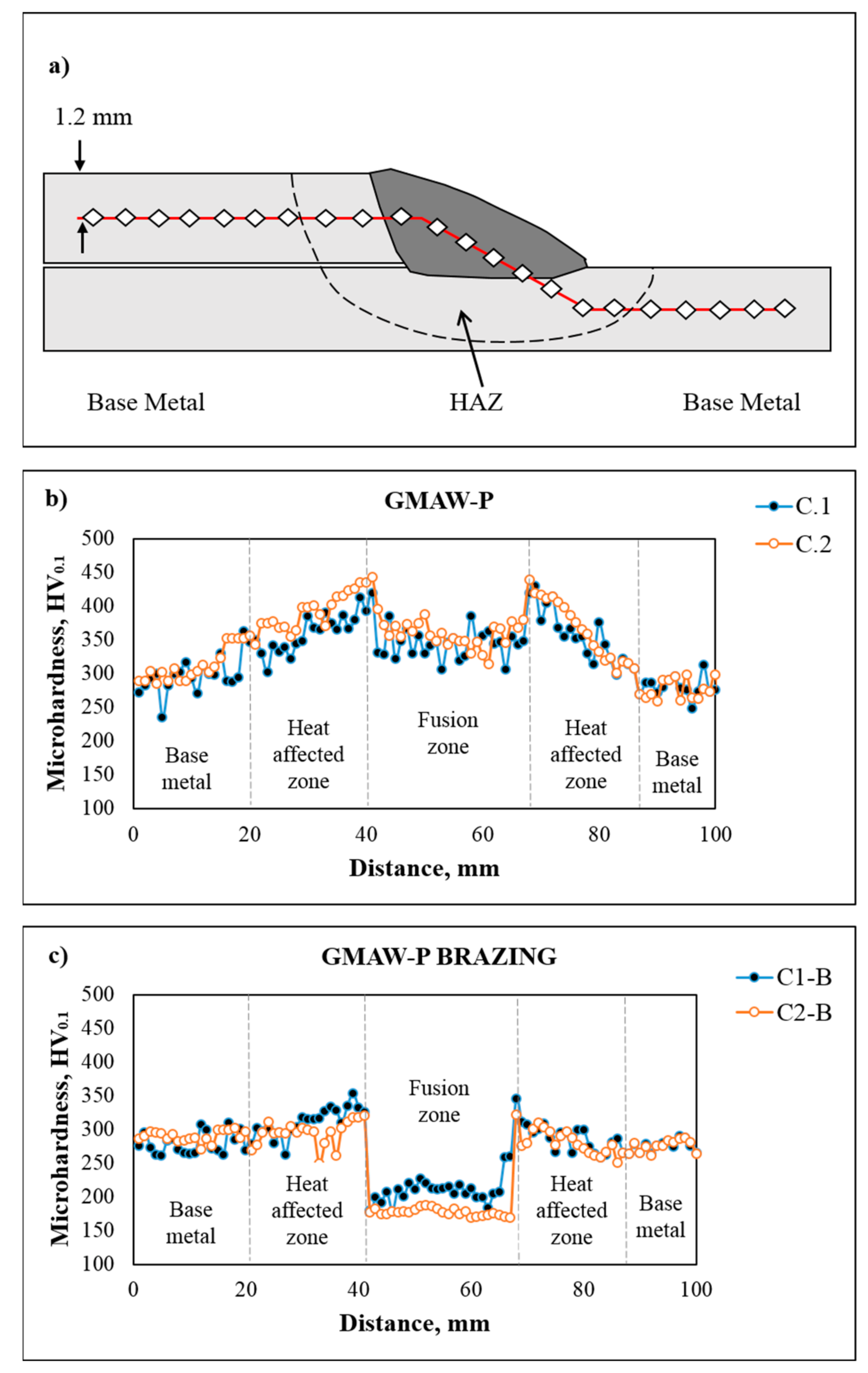
Figure 8 shows the microhardness profiles for the welded joints. Figure 8a schematically represents the zones where the microhardness measurements were performed in the BM and the FZ. Figure 8b represents the GMAW-P process, where the maximum hardness measured was 440 HV and was located at the HAZ close to the FZ; this finding confirms the bainitic transformation previously observed in the microstructure. The average hardness in the FZ was 350 HV; this value is related to the transformation of acicular ferrite in the weld bead, where, for both conditions, they have a very similar behavior. Microhardness profiles are determined by the corresponding microstructure, which has been discussed as dependent on welding parameters, the chemical composition of the steel and the initial microstructure. Welding parameters such as welding speed affect the heat input, which has a great effect on properties after welding [26].
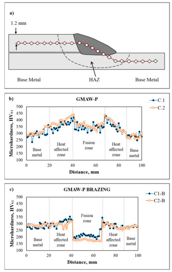
Figure 8.
Microhardness profiles; (a) schematic of the measurements made in the lap welded joints, (b) GMAW-P and (c) GMAW-P-brazing.
On the counter part, Figure 8c shows the hardness profiles for the GMAW-P-brazing process, where, in the FZ the average hardness for both conditions was 193 HV, due to the fact that the Cu-Al filler metal is a soft and ductile material [27]. At the interface near to the HAZ, the maximum hardness reported was 320 HV. The hardness in the HAZ increased to around 345 HV due to the presence of martensite and bainite in this zone.
The lap welded joints were tested under tension by applying load until rupture. Due to the fact that the welds are overlapping joints, it is not possible to determine the stress applied during the test, so care was taken in the width of the dimensions of the specimens before every test to make them comparable. Shing et al. described three types of failure modes that can occur in lap joints as shown in Figure 9. The failure of the specimens tested in this work occurred as depicted in mode 2; this type of failure is described as crack initiation from the root and propagation along the vertical interface [28]. It can be seen that in both cases, in conditions C1 and C2 for the GMAW-P and GMAW-P-brazing joints, the fracture occurs at 45° with respect to the load application, since this direction presented the maximum stress during the test.
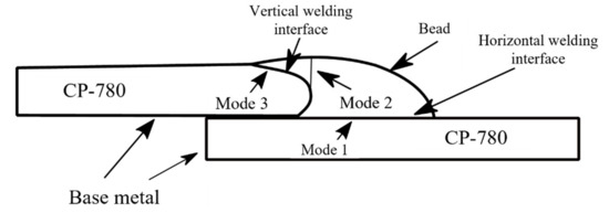
Figure 9.
Failure modes in lap welded joints, adapted from [13].
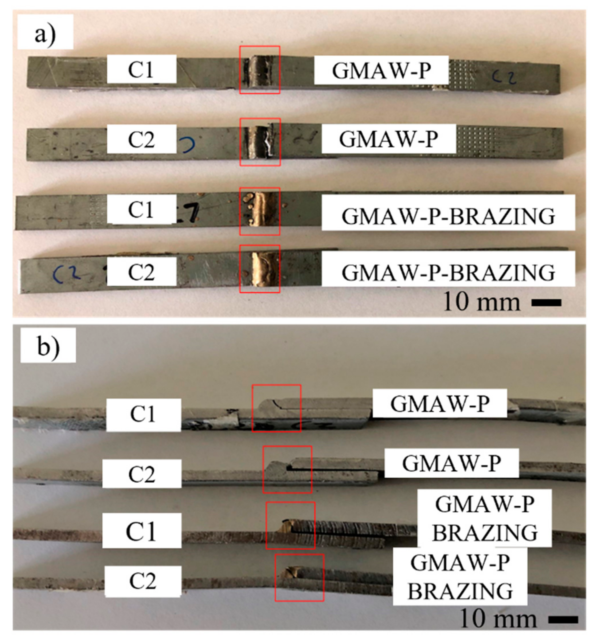
Figure 10 shows the specimens tested and the fracture zones for the different welding conditions. Figure 10a shows the top view, whereas Figure 10b shows the side view. All the joints failed in the FZ and the maximum tensile strength was found in specimen C2-B, which corresponds to condition 2 of the GMAW-P-brazing process, and the lowest resistance was in specimen C2, which corresponds to condition 2 of the GMAW-P process.

Figure 10.
Macrographs of the lap welded joints for pulsed and pulsed-brazing specimens after tensile testing: (a) top view and (b) transverse view.
Table 3 summarizes the results of the tensile tests and the failure obtained from GMAW-pulsed and pulsed-brazing samples. First of all, the pulsed-brazing specimens broke under higher loads irrespective of the heat input as compared to the pulsed specimens. The difference in mechanical resistance in the specimens may be ascribed to different defects such as pores, phases and intermetallic compounds that occur in the joints already mentioned above in the microstructural characterization. It can be seen that the failure occurs at 45° with respect to the normal; this may be due to the fact that the maximum stress occurs in this direction in the tensile test [28].
Table 3.
Mechanical properties of the lap welded joints specimens.
Figure 11 shows the load versus elongation plots of the tensile tests; the red and blue lines represent condition 1 (C1) and 2 (C2), respectively, of the GMAW-P process, while the black and green lines correspond to conditions 2 (C2-B) and 1 (C1-B), respectively, for the GMAW-P-brazing process. As can be seen, the highest tensile strength was found in the specimens welded with the GMAW-P-brazing process. The elongation in the brazing welds was 1 mm, twice larger in comparison to the joints welded with the ER80S electrode.
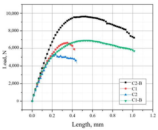
Figure 11.
Load versus length curves of the CP lap welded joints.
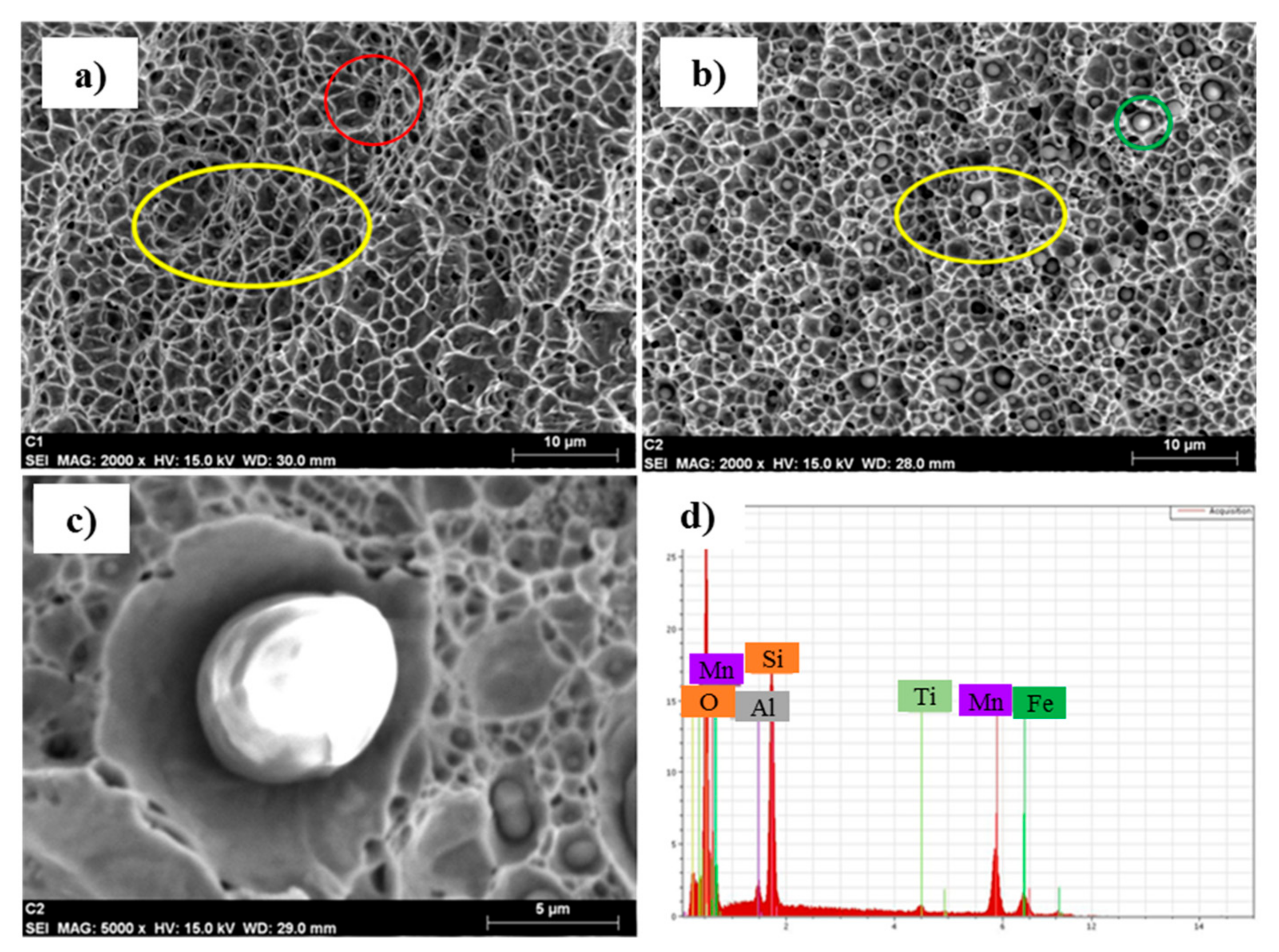
Fractures of the weldments were analyzed by means of SEM to observe the topographical characteristics of the failure. Figure 12 shows the fracture of the GMAW joints welded with the ER 80S electrode. Figure 12a,b show conditions 1 and 2 (C1 and C2), respectively. The high heat input sample is characterized by fine equiaxed microdimples (yellow circles), whereas the low heat input fracture also exhibits microcavities, but larger in size and with some elongation in the direction of load application; this difference is related to the cooling rates in the fusion zone as dictated by the heat input. Nevertheless, both fracture surfaces are representative of ductile failures [29]. The presence of microporosities (red circle), like the one enclosed in red in Figure 12a, was found. The presence of pores in the weld metal is due to trapped gases produced by the evaporation of zinc during the welding process [30]. In the lap welding of zinc-coated steels, the formation of a high-pressure zinc vapor is generated on the contact surfaces between the upper and lower sheets caused by the heat input during welding; this produces defects such as porosity and cracking in the weld bead. The melting point of carbon steel is about 1500 °C, which is approximately 600 °C higher than the boiling point of pure zinc (906 °C). These differences in the properties of the BM with the coating results in the formation of a high-pressure zinc vapor at the contact surfaces between the zinc-coated steel sheets during the GMAW process [31,32]. Spherical particles (green circle) were observed within the microdimples of the fractures (see Figure 12c); the EDS analysis presented in Figure 12d of the inclusions confirms that they are Ti, Si and Mn oxides. Lee y col. [33] observed that acicular ferrite in the weld bead is prone to form this type of inclusion when there are elements such as Ti, Si, Al and Mn in the weld pool at temperatures above 2000 °C.

Figure 12.
Fracture of the GMA welds with the ER 80S electrode: (a) low heat input, (b) high heat input, (c) analyzed particle and (d) EDS spectrum.
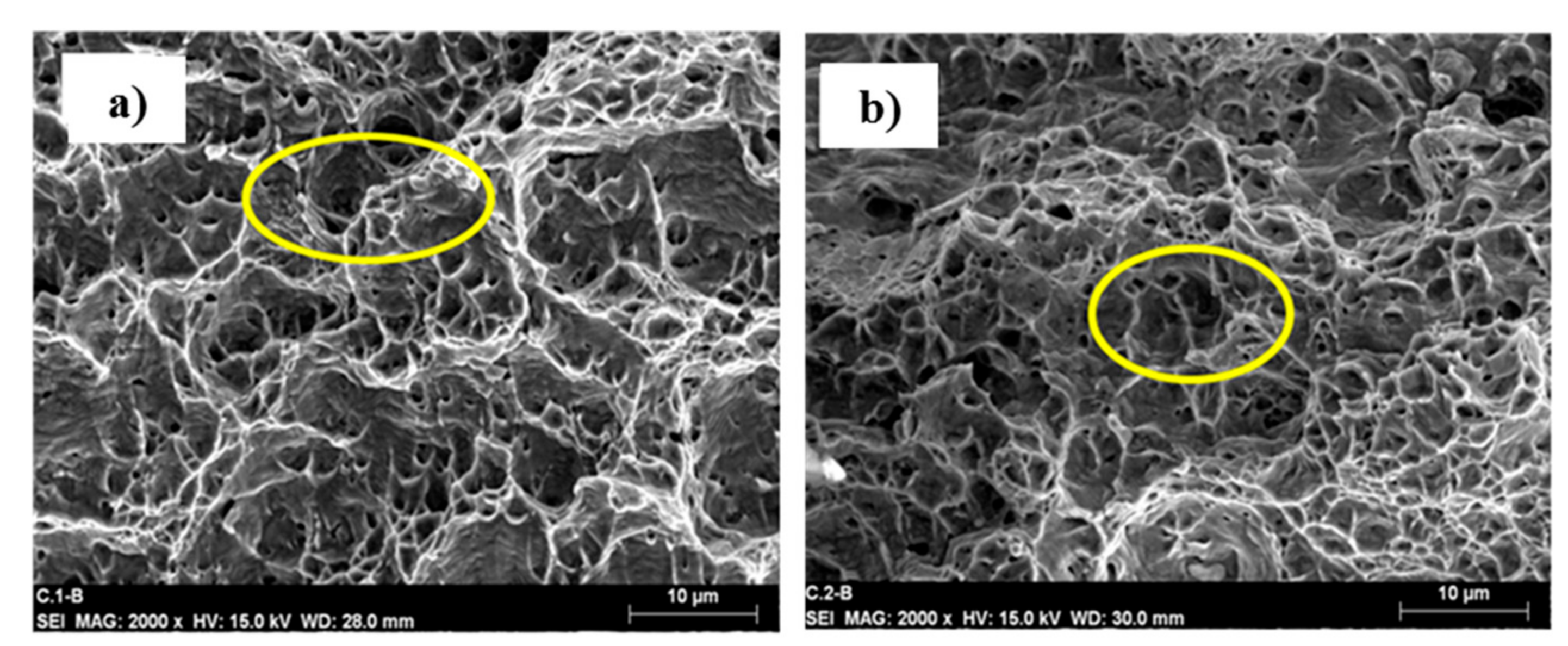
Finally, Figure 13a,b shows the fractures obtained from the pulsed-brazing joints in the lap welded joints for low and high input. Small equiaxed and large elongated microcavities are observed in the ductile fractured surfaces of these specimens (yellow circles). The deformation of the dimples develops with the quasi-static load of the tensile test until it reaches fracture. Primary cavities and secondary microcavities with a great deformation are observed, which correlates with the ductility observed in the tension tests, where the joints presented a greater elongation as compared to the joints welded with the ER80S electrode.
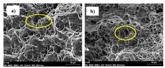
Figure 13.
Fracture of the GMAW-P-brazing for (a) low heat input and (b) high heat input.
3.4. Free Fall Testing
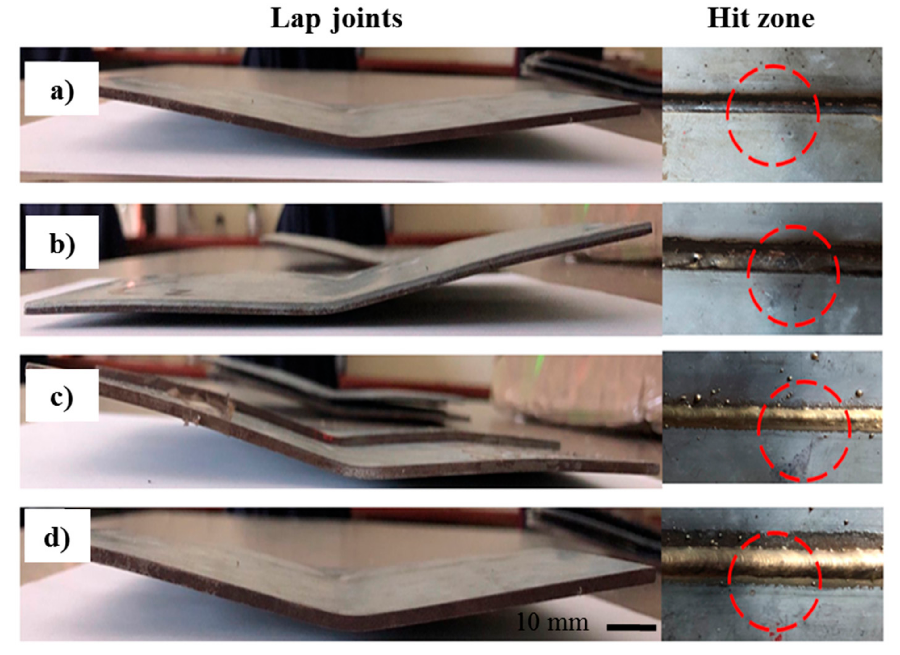
Figure 14 shows the specimens after the free fall test and the area (red circles) where the hammer hits the specimen. The tested specimens did not present fractures or cracks caused by the hammer; lap welded joints were only deformed as a result of energy absorption. Figure 14a,b represent condition 1 (C1) and condition 2 (C2) of the GMAW-P process, respectively, where the ER80S-D2 electrode was used, and Figure 14c,d represent condition 1 (C1-B) and condition 2 (C2-B) of the GMAW-P-brazing process, respectively, which used the ERCuAl-A2 electrode.
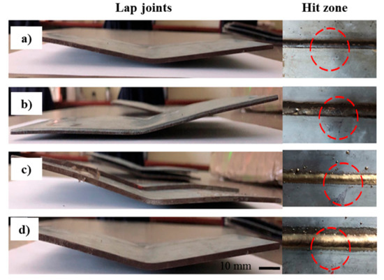
Figure 14.
Free fall test. (a) GMAW-P low heat input, (b) GMAW-P high heat input, (c) GMAW-P -brazing low heat input and (d) GMAW-P-brazing high heat input.
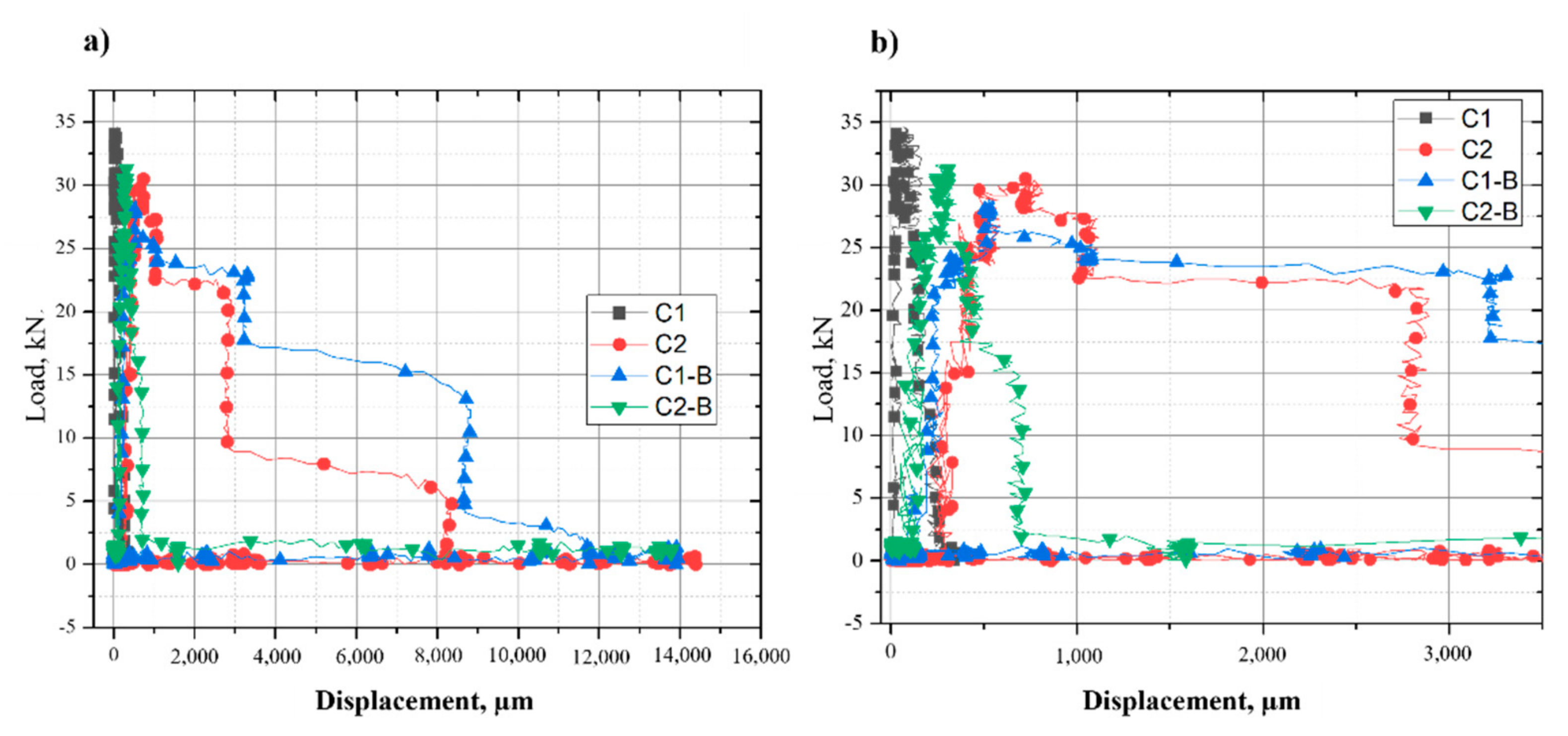
Figure 15 shows the plot force versus displacement, where the largest displacement occurs in condition 1 (C1-B) for the GMAW-P-brazing process and the smallest displacement (see Figure 15b) occurs in condition 1 (C1) for the GMAW-P process. Svenson et al. [34] found that acicular ferrite in more than half of the weld bead seems to be the key to improving impact resistance, due to the grain size of this phase. However, in the present investigation, it is observed that in condition 2 (C2) when using the ER80S-D2 electrode in the CP 780 steel, the acicular ferrite phase is generated in the weld bead, which is characterized by having good mechanical properties such as toughness, but when using the GMAW-P welding process with high heat input, a larger HAZ is generated, including inclusions, larger grain growth and other defects such as porosity and cracks. These defects are known to decrease the mechanical properties of these joints [35]. The loss of ductility in GMAW-P welding can also be associated with the presence of titanium oxide microspheres, since during welding, acicular ferrite is a precursor for the formation of this type of inclusion at high temperatures (i.e., 2200 °C) [33]. Other factors that affect the vertical impact test are the grain size and the dimensions of the weld bead. In welded joints, a refined grain size in the HAZ improves the mechanical properties of the materials, such as toughness. In fusion welding, the grain size is related to the heat input; thus, for low heat input the grain size in the HAZ is smaller as compared to that for high heat input [36].
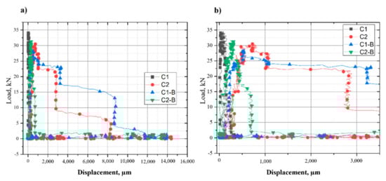
Figure 15.
Load versus displacement behavior of the free fall tests, (a) full assay, and (b) amplified zone.
4. Conclusions
According to the experimental results obtained from this study of the pulsed GMAW welding process using an ER80S-D2 and ER CuAl-A2 electrode, the following conclusions may be drawn: the fusion zone presented acicular ferrite, whereas in the HAZ, a combination of lath-type martensite and upper bainite was found in the joints welded with the ER80S-D2 electrode; defects such as pores caused by the evaporation of the Zn coating were found in the weld bead, leading to a decrease in mechanical properties.
In the joints welded with the ERCuAl-A2 electrode, partial melting of the BM with the FZ was observed, showing dendritic growth of the Cu-rich microstructure. On the other hand, in the HAZ, a combination of martensite, bainite and ferrite phases was found. Between the FZ and the HAZ, an intermetallic complex compound of Cu, Al and Fe was found, which was related to the improvement of the mechanical properties of the joint.
The best tensile strength was found in the condition with a high heat input of the GMAW-P-brazing process as compared to that of the GMAW-P process, resulting in major impact toughness. The fracture zone of the tensile specimens was in the FZ, where all the specimens exhibited ductile fracture. In condition 2 with a high heat input, the GMAW-P welding process presented inclusions of Mn, Si and Ti generated by the temperature during welding.
Author Contributions
A.J.R.-O. performed most of the experimental work and wrote the original manuscript; J.J.T.-T. provided materials and discussed the results; R.D.L.-A. provided the GMAW power sources and discussed the results; V.H.L.-M. supervised experimental work, reviewed and edited the manuscript; M.d.C.R.-L. assisted with experimental work, data analysis and discussion of the results; M.S.-M. discussed the results and edited the manuscript; F.F.C.-L. conceived the study, acquired funding and edited the manuscript. All authors have read and agreed to the published version of the manuscript.
Funding
This study was supported by Coordinación de la Investigación Científica of Universidad Michoacana de San Nicolas de Hidalgo, Approved project announcement 2022.
Institutional Review Board Statement
Not applicable.
Informed Consent Statement
Not applicable.
Data Availability Statement
Data is contained within the manuscript.
Acknowledgments
A.J.R.-O. thanks CONACyT-Mexico for providing a scholarship for his master studies.
Conflicts of Interest
The authors declare no conflict of interest.
References
- Liang, X.; Wang, Y.; Chen, Y.; Deng, S. Advances in Emission Regulations and Emission Control Technologies for Internal Combustion Engines. SAE J. STEEP 2021, 2, 101–119. [Google Scholar] [CrossRef]
- Gould, J.; Khurana, S.; Li, T. Predictions of microstructures when welding automotive advanced high-strength steels. Weld. J. 2006, 85, 111. [Google Scholar]
- Shaw, J.; Engl, B.; Espina, C.; Oren, E.C.; Kawamoto, Y. ULSAB-advanced vehicle concepts–materials. SAE Tech. Paper 2002, 111, 21–29. [Google Scholar]
- Lopez-Cortez, V.; Reyes-Valdes, F.J.W.J. Understanding resistance spot welding of advanced high-strength steels. Weld. J. 2008, 87, 36–40. [Google Scholar]
- Cortez, V.H.L. Soldabilidad de Aceros Avanzados de Alta Resistencia AHSS Tipo Martensíticos Mediante Soldadura de Puntos Por Resistencia RSW en Componentes Automotrices. Ph.D. Thesis, COMIMSA, Saltillo, México, 30 January 2009. Available online: http://comimsa.repositorioinstitucional.mx/jspui/handle/1022/162 (accessed on 1 February 2022).
- DeRuntz, B.D. Assessing the benefits of surface tension transfer welding to industry. J. Ind. Technol. 2003, 19, 2–8. [Google Scholar]
- ESAB. ESAB Aristo Superpulse Expands Pulse MIG/MAG. Available online: http://www.esab.ch/global/en/news/ESAB-Aristo-SuperPulseexpands-pulse-MIGMAG.cfm (accessed on 1 February 2022).
- Kah, P.; Suoranta, R.; Martikainen, J. Advanced gas metal arc welding processes. Int. J. Adv. Manuf. Tech. 2013, 67, 655–674. [Google Scholar] [CrossRef]
- Kim, Y.; Park, K.; Kwak, S. A review of arc brazing process and its application in automotive. Int. J. Mech. Eng. Robot. Res. 2016, 5, 246. [Google Scholar] [CrossRef]
- Li, J.; Li, H.; Wei, H.; Ni, Y. Effect of pulse on pulse frequency on welding process and welding quality of pulse on pulse MIG welding-brazing of aluminum alloys to stainless steel. Int. J. Adv. Manuf. Tech. 2016, 87, 51–63. [Google Scholar] [CrossRef]
- Shome, M. Metal Inert Gas (MIG) brazing and friction stir spot welding of advanced high-strength steels (AHSS). In Welding and Joining of Advanced High Strength Steels (AHSS); Elsevier: Amsterdam, The Netherlands, 2015; pp. 137–165. [Google Scholar]
- Berczeli, M.; Weltsch, Z. Experimental Studies of Different Strength Steels MIG Brazed Joints. Period. Polytech. Trans. Eng. 2019, 47, 13. [Google Scholar] [CrossRef]
- Singh, J.; Arora, K.S.; Shajan, N.; Shukla, D.K.; Shome, M. Role of bead shape and dispersed intermetallic phases in determining the strength of CMT brazed DP780 lap joints. J. Manuf. Process. 2019, 44, 207–215. [Google Scholar] [CrossRef]
- Varol, F.; Ferik, E.; Ozsarac, U.; Aslanlar, S. Influence of current intensity and heat input in Metal Inert Gas-brazed joints of TRIP 800 thin zinc coated steel plates. Mater. Design 2013, 52, 1099–1105. [Google Scholar] [CrossRef]
- E407-07; Standard Practice for Microetching Metals and Alloys. ASTM: West Conshohocken, PA, USA, 2015.
- E384-17; Standard Test Method for Microindentation Hardness of Materials. ASTM: West Conshohocken, PA, USA, 2017.
- E208-06; Standard Test Methods for Conducting Drop-Weight Test to Determine Nil-Ductility Transition Temperature of Ferritic Steels. ASTM: West Conshohocken, PA, USA, 2012.
- Jewett, J.W.; Serway, R.J.V. Physics for Scientists and Engineers with Modern Physics, 9th ed.; Brooks/Cole: Boston, MA, USA, 2012. [Google Scholar]
- E-112; Standard Test Methods for Determining Average Grain Size. ASTM: West Conshohocken, PA, USA, 2013.
- Poliak, E.; Pottore, N.; Skolly, R.; Umlauf, W.; Brannbacka, J. Thermomechanical processing of advanced high strength steels in production hot strip rolling. Metallurgia Italiana 2009. Available online: http://www.esis-ph.eu/index.php/aim/article/download/383/352 (accessed on 1 February 2022).
- E562-02; Standard Test Method for Determining Volume Fraction by Systematic Manual Point Count. ASTM: West Conshohocken, PA, USA, 2013.
- Li, X.; Ramazani, A.; Prahl, U.; Bleck, W. Quantification of complex-phase steel microstructure by using combined EBSD and EPMA measurements. Mater. Charact. 2018, 142, 179–186. [Google Scholar] [CrossRef]
- Guzman-Aguilera, J.J.; Martinez-Gonzalez, C.J.; Baltazar-Hernandez, V.H.; Basak, S.; Panda, S.; Razmpoosh, M.; Gerlich, A.; Zhou, Y. Influence of SC-HAZ microstructure on the mechanical behavior of Si-TRIP steel welds. Mater. Sci. Eng. A 2018, 718, 216–227. [Google Scholar] [CrossRef]
- De Bruycker, E.; De Cooman, B.; De Meyer, M. Galvanizability of complex phase high strength steel. Metal. Mater. Trans. A 2004, 75, 147–152. [Google Scholar] [CrossRef]
- Singh, J.; Arora, K.S.; Shukla, D. Dissimilar MIG-CMT weld-brazing of aluminium to steel: A review. J. Alloy. Compd. 2019, 783, 753–764. [Google Scholar] [CrossRef]
- Roncery, L.M.; Weber, S.; Theisen, W. Welding of twinning-induced plasticity steels. Scripta Mater. 2012, 66, 997–1001. [Google Scholar] [CrossRef]
- Marconi, C.; Consigli, C.; Castillo, M.J.; Svoboda, H. Efecto de los Parámetros de Proceso sobre las Propiedades Mecánicas de Uniones GMAW-Brazing de Acero DP 1000. Soldagem Inspeção 2020, 25. [Google Scholar] [CrossRef]
- Lewinsohn, C.A. Mechanical Behavior of Materials by Norman E. Dowling. Mater. Manuf. Processes 2000, 15, 775–776. [Google Scholar] [CrossRef]
- Bagnoli, D.L.; Rafael, K.B. Fractography Handbook; Woohead Publishing: Cambridge, UK, 1987; pp. 37–450. [Google Scholar]
- Vezzù, S.; Scappin, M.; Boaretto, D.; Timelli, G. On the Effect of slight variations of Si, Mn, and Ti on inclusions properties, microstructure, and mechanical properties of YS460 C-Mn steel welds. Metall. Microstr. Analysis 2019, 8, 292–306. [Google Scholar] [CrossRef]
- Saha, D.C.; Chang, I.; Park, Y. Heat-affected zone liquation crack on resistance spot welded TWIP steels. Mater. Charact. 2014, 93, 40–51. [Google Scholar] [CrossRef]
- Yu, J.; Kim, D. Effects of welding current and torch position parameters on minimizing the weld porosity of zinc-coated steel. Int. J. Adv. Manuf. Tech. 2018, 95, 551–567. [Google Scholar] [CrossRef]
- Lee, S.; Kim, J.-H.; Barlat, F. Multi-Coefficient Optimization of Homogeneous Anisotropic Hardening Model for Ahss. Proc. IOP Conf. Ser. Mater. Sci. Eng. 2019, 651, 012018. [Google Scholar] [CrossRef]
- Svensson, L.; Gretoft, B. Microstructure and impact toughness of C-Mn weld metals. Weld. J. 1990, 69, 454. [Google Scholar]
- Jones, N. Impact loading of ductile rectangular plates. WIT Trans. Built Env. 2010, 113, 71–81. [Google Scholar]
- Xu, W.; Wang, Q.; Pan, T.; Su, H.; Yang, C. Effect of welding heat input on simulated HAZ microstructure and toughness of a VN microalloyed steel. J. Iron Steel Res. Int. 2007, 14, 234–239. [Google Scholar] [CrossRef]


Publisher’s Note: MDPI stays neutral with regard to jurisdictional claims in published maps and institutional affiliations. |
© 2022 by the authors. Licensee MDPI, Basel, Switzerland. This article is an open access article distributed under the terms and conditions of the Creative Commons Attribution (CC BY) license (https://creativecommons.org/licenses/by/4.0/).