Article

A Numerical Simulation of Machining 6061 Syntactic Foams Reinforced with Hollow Al2O3 Shells

1
Department of Mechanical Engineering, American University of Sharjah, Sharjah P.O. Box 26666, United Arab Emirates
2
Department of Mechanical Engineering, Rochester Institute of Technology, Dubai P.O. Box 341055, United Arab Emirates
3
Department of Mechanical Engineering, BITS Pilani, Dubai P.O. Box 345055, United Arab Emirates
*
Author to whom correspondence should be addressed.
Metals 2022, 12(4), 596; https://doi.org/10.3390/met12040596
Submission received: 28 February 2022 / Revised: 19 March 2022 / Accepted: 24 March 2022 / Published: 30 March 2022
(This article belongs to the Special Issue Sustainable Manufacturing of Light Alloys)

Abstract

:
Aluminum closed cell syntactic foams possess reduced density, higher peak compression strength, and lower coefficient of thermal expansion and thermal conductivity compared to metal alloys. However, the industrial mass production of these complex material systems presents a significant problem in the form of poor machinability. In order to address this concern and to increase the use of this potential cost- and energy-saving system, a two-dimensional numerical model using the AdvantEdgeTM machining software was developed. For the verification of the numerical model, machining trials in dry conditions were conducted on different samples using a SandvikTM carbide-coated insert having a 6° rake angle and a 7° clearance angle. The hollow alumina shell diameter and volume fraction were found to profoundly affect the magnitude of the generated machining forces. This study showed an increase in machining force by almost 25% for syntactic foams reinforced with hollow alumina shells of higher volume fraction and coarser diameters. The cutting conditions to obtain a favorable stress diastribution in the syntactic foam’s machined sub-surface were identified.

1. Introduction

Aluminum-based syntactic foams are synthesized by filling the metal matrix with hollow abrasive micro/nano-sized shells. The development of this class of materials is well suited for front suspension casting, bumper housing casting, and side-impact beams used in automotive applications [1]. This special type of closed-cell foam possesses excellent characteristics: optimal strength to weight ratio, reduced thermal expansion coefficient and thermal conductivity, along with good damage tolerance which are important traits for impact applications [2,3]. They provide the benefits of high peak strength and excellent energy absorption capabilities, which makes them a better candidate compared to other commonly used systems for backup plates used in armor ballistic plates and bulletproof vests [4,5]. Just like aluminum (Al) foams, syntactic foams can potentially be applied in the manufacture of automotive brake rotors and differential covers. Due to superior wear resistance in comparison to conventional alloys, aluminum-based syntactic foams can be used in brake lining applications [6,7]. Every automotive industry is giving high priority to the problem of total weight and fuel efficiency for the reduction of environmental pollution and hazardous gas emission. On this basis, there is a possibility for syntactic foams to be used in cars’ bumper beam and pillar reinforcements, thereby achieving weight reduction [8]. Being lightweight and having a high energy absorption, Aluminum-based syntactic foams can be used for armor enhancement in military vehicles and blast-resistant structures [9].
These properties have promoted the force analysis of syntactic foams during machining, which could be used to manufacture advanced useful products at a lower manufacturing cost. Bolat et al. [10] investigated the machining characteristics of pumice-reinforced aluminum alloy 7075 syntactic foams machined by face turning. The authors concluded that machining forces (cutting, feed, and radial forces) increase with the rising cutting speed, keeping the feed rate constant due to the thermal softening of the AA matrix and the porous nature of the pumice particles. Kannan et al. [11] elucidated the machining mechanics of a 7075-based syntactic foam via an analytical force model. Their key observations were: (a) the work hardening of 7075 matrix was influenced by the presence of smaller hollow alumina shells in the matrix and (b) higher cutting forces were generated with a higher volume fraction and a finer average size of the shell. Kannan et al. [12] also studied the machinability of an AZ91 magnesium alloy-based syntactic foam. An important observation by these authors was the rise in cutting force values by 100 N due to the pinning action of the hollow shell along the grain boundaries, thereby leading to a higher hardening of the matrix. Alhourani et al. [13] developed a constitutive model to explain the machining of an AZ31 magnesium syntactic foam reinforced with hollow alumina shells. From the author’s results, the main conclusion was a spike in friction forces with the increasing volume fraction of hollow shells. Many studies also performed a force analysis of metal foams during machining. Ullen [14] evaluated the machinability of Cu–Ni –Mo-based steel foams with different porosities produced by powder metallurgy. The main finding after performing drilling studies was a decrease in thrust forces with an increase in porosity content due to brittle fractures around the pores which led to lower cutting forces. Guerra-Silva et al. [15] analyzed the cutting conditions and tool geometry on orthogonal machining of cellular heat-resistant austenitic stainless steel using the finite element (FE) method. The authors noted a larger cutting force with an increase in the cutting speed and/or the depth of the cut due to the non-homogenous nature of the material.
Even though force analyses were conducted on syntactic foams and cellular metals, there are limited studies elucidating the interaction between the reinforcement hollow shell and the matrix using the finite element method. In this paper, an attempt was made to develop a two-dimensional (2D) FE model using AdvantEdgeTM software for predicting cutting forces and cutting temperature distribution during the machining of 6061 aluminum-based syntactic foams. With the FE model, the distribution of machining-induced stresses beneath the cutting layer was also predicted and analyzed. This distribution analysis will help to identify the favorable machining parameters and average size of hollow alumina shells, which will help to improve the product’s performance in service.
This paper attempted to develop a simplified FE model that can be used by manufacturing engineers to characterize the machining forces and temperature distribution when cutting closed cell syntactic foams. This simplified syntactic foam model will also help to visualize the machining-induced stresses, which is of significance to understand the fatigue life of the components in service. This simulation aimed to reduce the time required to model complex syntactic foam materials and its cost through visualization of machining-induced quality defects on the different components. To the authors’ knowledge, this is the first machining model developed for a closed cell syntactic foam system. Machining trials were carried out to verify the developed FE model, which showed reasonable agreement with experimental measurements.

2. Materials and Methods

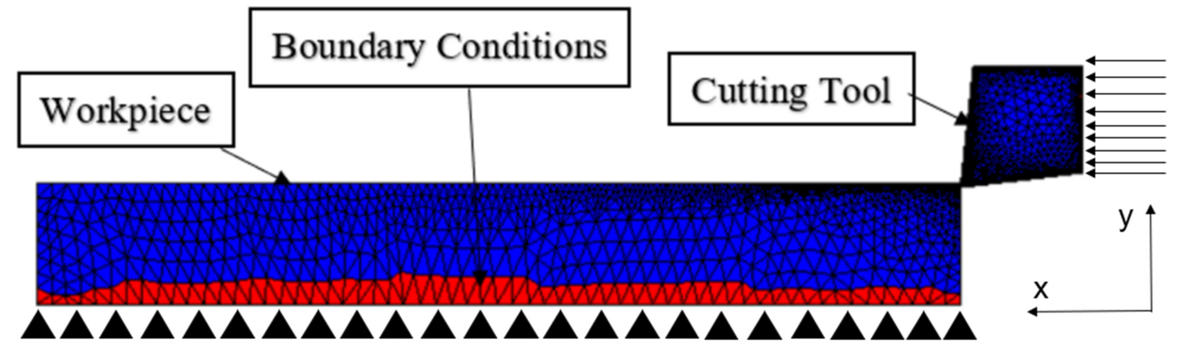
2.1. Numerical Model of the Machining of Aluminum Closed Cell Syntactic Foams
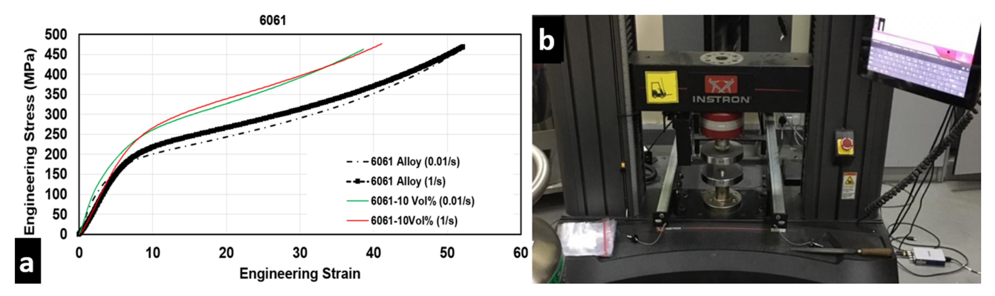
To simulate the machining forces and cutting temperature generated in the process, the AdvantEdgeTM 7.7, a numerical simulation software developed by Third Wave Systems USA, was employed. For workpiece modelling in AdvantEdgeTM software, the maximum workpiece length was 10 mm depending on the required convergence. Constraints were placed on the base and left side of the workpiece for boundary conditions, as shown in Figure 1. This was done so that the tool was constrained to move in the x-direction, and the workpiece was fixed. As a result, the cutting tool and workpiece would have a relative motion, which was the cutting speed. The boundary conditions for the cutting velocity and undeformed chip thickness of the tool were established on the reference point, which was at the cutting edge of the tool. The workpiece mesh and cutting tool mesh were created using a tri-element mesh. For improving the computational efficiency, the minimum and maximum mesh sizes of the workpiece were 20 μm and 100 μm, respectively, and were used in AdvantEdgeTM software.

2.2. Material Model

In AdvantEdgeTM software, the relationship between material stress and strain is described by a user-defined yield surface material model based on Johnson and Cook (JC) model constants. In this software, to simplify the material modelling of this highly complex heterogeneous material system, the material model was assumed to be equivalent to a homogenous model. The chemical composition of the 6061-based syntactic foam is summarized in Table 1, and the physical and mechanical properties of the 6061 matrix and hollow alumina shell are shown in Table 2.
The plastic deformation behavior for the 6061 matrix was modelled using the Johnson–Cook material model. The JC model shows the dependency of the flow stress on strain, strain rate, and temperature. The constants for the model were obtained from stress–strain–temperature tests. A series of compression tests were conducted on squeeze-casted samples at different strain rates and temperatures using an Instron universal testing machine (see Figure 2b), from which the material model constants were determined. A representative stress–strain curve is shown in Figure 2a. Based on the experiments conducted at different temperatures and strain rates, quasi-static compression testing was used to calculate the yield stress (A = 150 MPa) and strain hardening parameters (B = 450 MPa and n = 0.39) at reference strain rate (1/s) and temperature (20 °C). Experiments conducted at different strain rates at constant temperature were used to determine the dimensionless strain rate sensitivity parameter (C = 0.012). Experiments performed at different temperatures and constant strain rate were used to determine the thermal softening coefficient (m = 0.5). The key properties of the 6061 matrix and the reinforcement hollow alumina shell (supplier data) and the properties of the cutting tool material which were used in AdvantEdgeTM are reported in Table 2 and Table 3, respectively.

2.3. Chip Separation Criterion

In AdvantEdgeTM, the chip separation criteria are an essential part of the orthogonal machining simulation. Normally, there are two types of techniques for chip separation: the node splitting and the element deletion techniques. In the case of node splitting, a chip separation plane is predefined, and a separation criterion is applied. There are two types of separation criteria which are normally geometrical and physical. Since the geometrical ones do not have physical meanings, they are assumed inferior in comparison to the physical ones. This makes the physical criteria much more suitable. The physical criteria make use of the critical value of a physical quantity for the estimation of the start of chip separation. Based on the input value of the reference strain rate present in the JC yield stress equation, a critical plastic strain to chip separation was used. The evolution of the damage variable with effective plastic displacement was assumed to be linear. There is an option to input the effective plastic displacement, U ¯ f p l , at the point of failure. The damage variable d increases based on the equation:
d = U ¯ ˙ p l U ¯ f p l
the chip separation criteria are enabled through material failure when the damage variable equals 1.

2.4. Chip–Tool Interaction

In AdvantEdgeTM, the sliding friction force is directly proportional to the applied normal load. The ratio of these two forces is the coefficient of friction, which is constant in all secondary shear zones formed between chip and cutting tool for different machining parameters. The frictional conditions between tool and chip in AdvantEdgeTM are modelled using the Coulomb friction model, which is shown below.
f f r = μ N
where f f r is the friction force exerted between the surfaces, μ is the coefficient of friction, and N is the normal force.

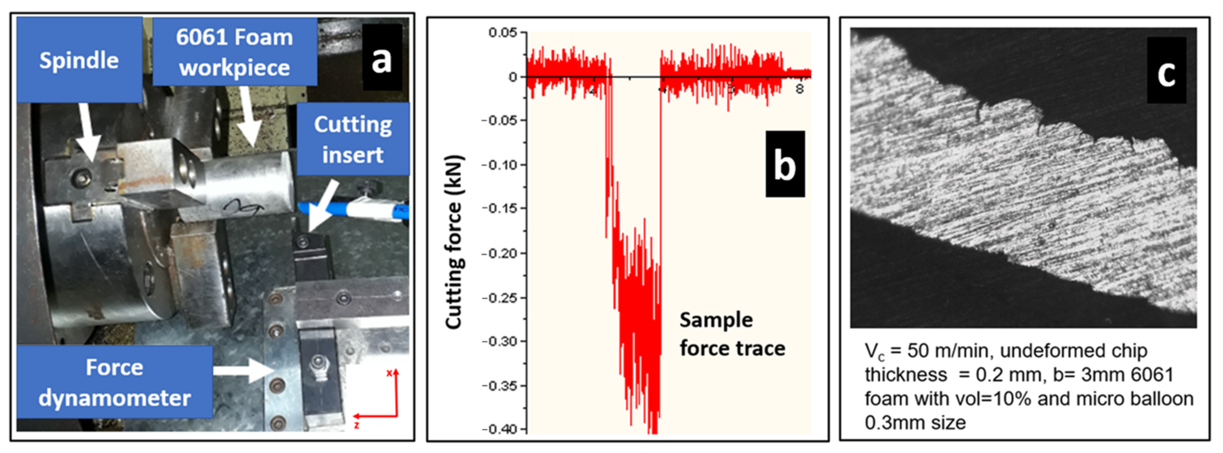
2.5. Experimental Validation

To validate the predicted force values of the 2D-FE model for metal syntactic foams, machining trials were carried out on 6061-based syntactic foams reinforced with hollow alumina shell (see Figure 3a). The complete set of cutting parameters is shown in Table 4. The cutting tool used in the tests was a Sandvik™ carbide-coated insert with a 6° rake angle and a 7° clearance angle. A KISTLER™ dynamometer was used along with a multichannel charge amplifier to measure the cutting forces from the force trace graph shown in Figure 3b. Trials were conducted twice to ensure repeatability, and the average were noted.

3. Results and Discussion

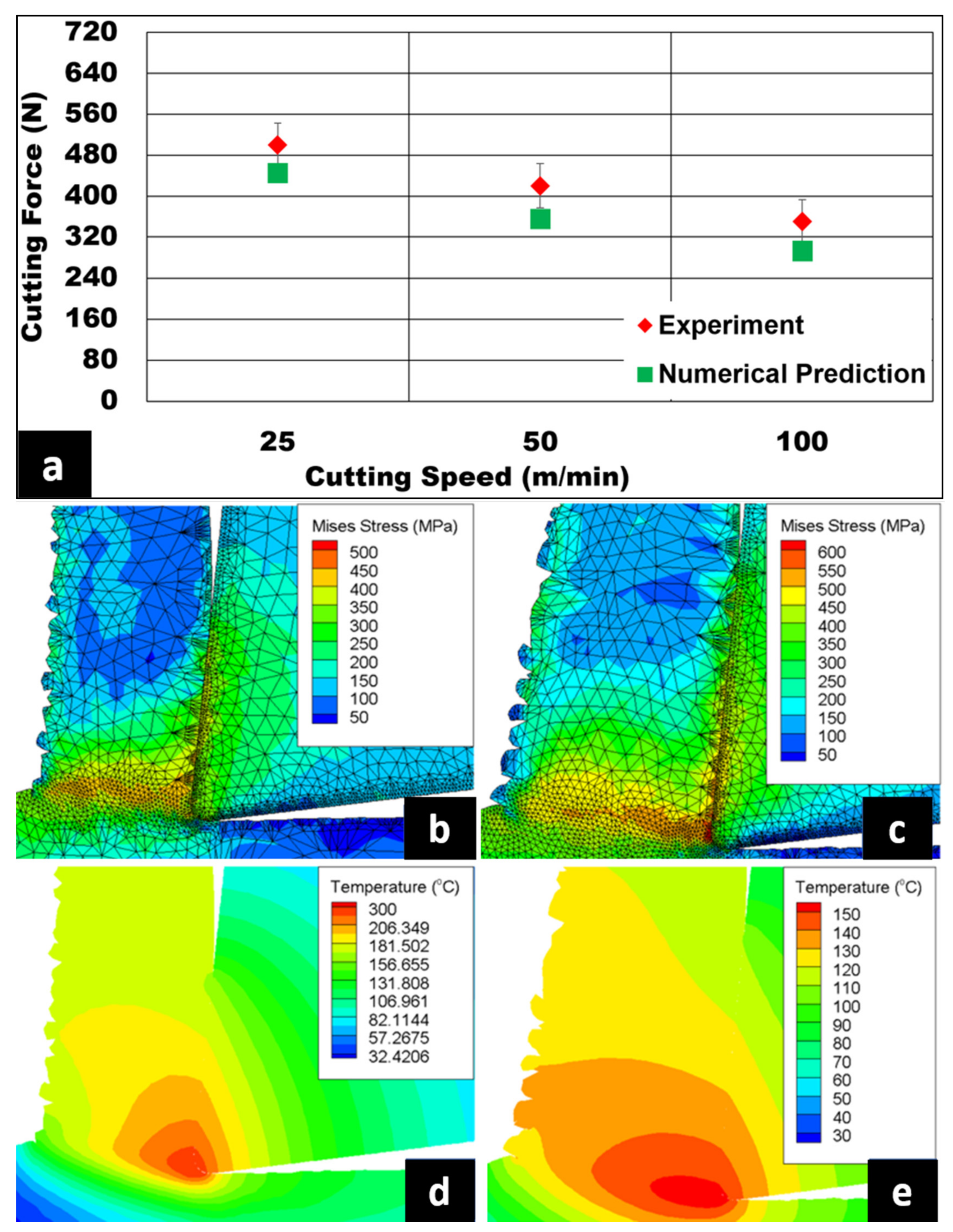
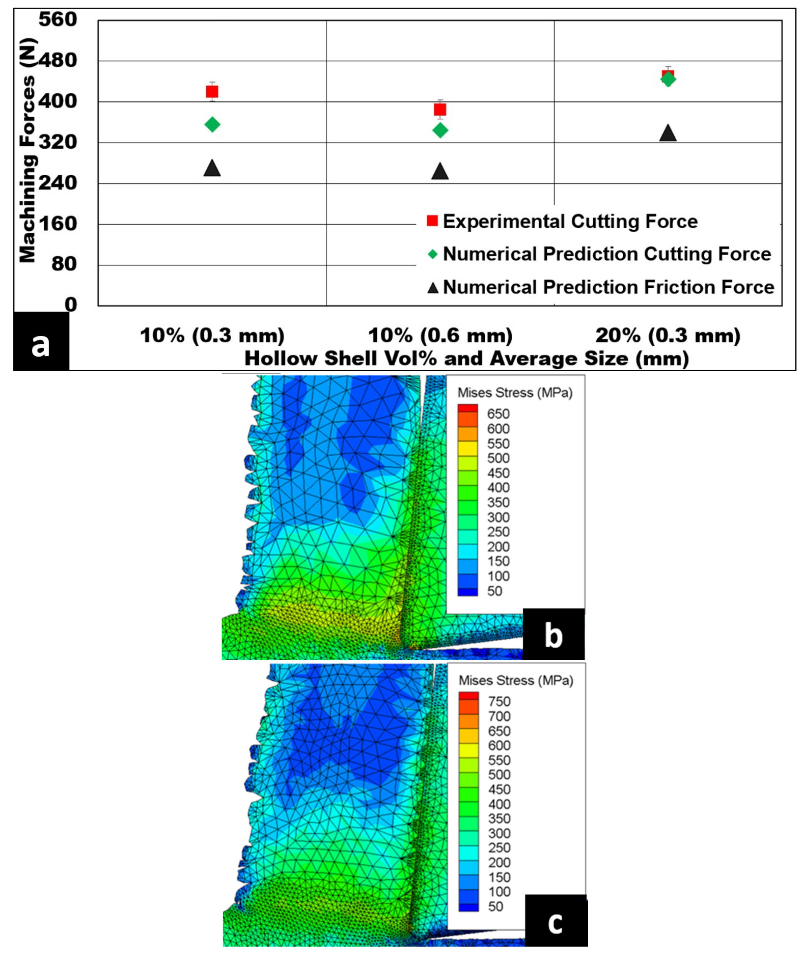
3.1. Machining Forces and Temperature Distribution

The influence of the cutting velocity on the cutting force during machining of 6061 reinforced with a 10% volume of alumina hollow shells is shown in Figure 4a. The measured cutting forces decreased with an increasing cutting speed by an order of up to 150 N, which was almost a reduction by 34%. The Von Mises stress contours at 100 m/min and 25 m/min are shown in Figure 4b,c. When the cutting velocity increased, the reduction in the length of shear plane was accompanied by an increase in shear angle and chip thickness ratio. Subsequently, the magnitude of the average shear force decreased, leading to a drop in the maximum shear stress required to cause plastic deformation in the primary shear zone. At a higher cutting speed, the material was subjected to a higher strain rate, which led to a reduction in chip compression ratio, chip–tool contact length (CTCL), and friction force. Under these conditions, an increase in the plastic strain rate by an order of four was observed through the numerical model. This reduced the heat dissipation in the primary and secondary shear zones, thus causing matrix thermal softening at higher cutting speeds (Figure 4d,e). This observation is in agreement with Kannan et al. [11] and Koklu [21], who observed the softening of the work material with increasing cutting speed. This phenomenon of matrix softening could promote the propagation of interfacial cracks, causing an accelerated debonding of hollow alumina reinforcement shells. This could promote the formation of a large volume of voids and pits on the machined surface, as a greater proportion of hollow alumina shells are pulled out of the matrix during the cutting operation.
Figure 5a shows the variation of undeformed chip thickness in relation to the generated cutting forces while cutting 6061 with 10% volume fraction of hollow alumina shell reinforcements at 50 m/min cutting speed. An increase in undeformed chip thickness resulted in an increase in the generated cutting forces by an order of 138%. The Von Mises stress contour images at 0.07 mm and 0.2 mm feed rates are presented in Figure 5b,c, respectively. A rise in uncut chip thickness with a constant cutting velocity led to a higher volume of metal cut. For an increase in the metal removal rate (MRR), the length of shear plane was observed to be increased, followed by an increase in the value of the chip thickness ratio. Subsequently, the average shear force as well as the maximum shear stress values were higher, as noted in the numerical simulation. This caused an increase in plastic strain at the primary and secondary shear zones. This means that a rise in uncut chip thickness caused an increase in chip load on the cutting tool, which required a higher magnitude of work to plastically deform the matrix, resulting in higher cutting forces.
The rise in cutting forces was also attributed to the presence of a larger volume fraction of hollow alumina shells in the shear zone pinning the 6061 aluminum grains. Due to work hardening of the aluminum matrix with increasing feed, higher specific energy was needed to initiate plastic deformation, which increased the stress in the primary shear zone, in agreement with Koklu and Kayhanlar [22]. Consequently, an increase in the magnitude of friction force was also observed from the simulation, as shown in Figure 6a, with increasing uncut chip thickness.
The proposed model was used to predict the friction forces caused by chip sliding mechanisms on the tool rake face (Figure 6). The key deformation mechanisms during cutting syntactic foams are plastic deformation of the matrix and debonding and fracturing of the hollow shells followed by densification of the matrix [11,12,13]. The fractured hollow ceramic shells were engaged in two-body and three-body abrasion of the cutting tool, which led to higher friction forces [13]. Both the FE method and experiments showed an increasing trend in the magnitude of the friction force and the force normal to the tool chip interface, with an increase in undeformed chip thickness. At a higher chip thickness ratio, the chip–tool contact length increased, with a subsequent increase in the number of hollow alumina shells at the primary and secondary shear zones. This resulted in alumina hollow shells sliding on the rake face of the tool, and consequently, an increase in friction force was noticed, as shown in Figure 6a. A corresponding increase in cutting temperature was also observed in the shear zones (primary and secondary), as displayed in Figure 6b.
The effect of hollow alumina shell volume percentage and its average size on the generated cutting force is shown in Figure 7a. A marginal increase in the generated cutting forces was noticed with an increasing volume fraction of hollow alumina shell reinforcements for given cutting speed and uncut chip thickness. The shear strength of the foam was expected to rise with an increasing volume fraction of hollow alumina shells. The simulation showed an increase in the magnitude of maximum shear force required to cause plastic deformation in the primary shear zone. A rise in the volume percentage of hollow alumina shells caused an increase in the number of hollow alumina shells along the shear zone pinning the matrix material. This caused higher energy consumption for matrix deformation that led to an increase in the generated machining force, as evidenced by the increased stress contour, as the volume fraction increased from 10% to 20% (Figure 7b,c).
The increase in the volume fraction of hollow alumina shells led to a rise in the number of hollow alumina shells flowing through the shear plane. This was accompanied by a higher plastic strain in the material at the primary and secondary shear zones. Subsequently, a reduction in the shear angle and an increase in the shear plane length led to higher values of the average shear force and maximum shear stress required to cut the material. This was primarily attributed to an increased work hardening of the matrix causing a rise in the generated cutting forces. Another way to elucidate the physics of cutting this material is the improvement in mechanical properties with increasing volume fraction due to increased pinning of the matrix flow by hollow alumina shells. A material with increased mechanical strength requires a higher magnitude of cutting forces, which agrees with Koklu et al. [23]. However, a rise in the average size of the hollow alumina shells caused a marginal drop in cutting forces. This was attributed to a larger proportion of defects in the form of pores and micro-cracks present in larger hollow alumina shells, leading to a faster defect propagation and to the ultimate fracture of hollow alumina shells. A coarser size of the hollow alumina shell at a constant volume fraction would lead to a smaller number of hollow shells to pin the matrix. Consequently, a smaller amount of plastic deformation would be experienced by the matrix, causing a reduction in the cutting forces. In the developed model, factors such as the hollow alumina shell volume fraction, the average size of the hollow alumina shells, and the ratio between the thickness of the hollow alumina shell wall and the hollow alumina shell diameter were incorporated.
Figure 7a also summarizes the variation of friction force with an increasing volume percentage of hollow alumina shells and their average sizes. The FE model predictions showed an increase in friction force with an increasing volume fraction of hollow alumina shell reinforcements and a slight decrease in friction force with coarser hollow alumina shell reinforcements. For same-average-sized hollow alumina shells, an increase in volume percentage led to an increase in the number of hollow alumina shells engaged in two-body and three-body abrasion mechanisms on the tool rake face contributing to an escalation in total friction and normal forces. This phenomenon was observed through the simulation results. However, for a fixed volume fraction, it was observed through the model that a decrease in hollow alumina shell size caused higher friction and normal forces compared to coarser hollow alumina shell sizes. This indicates that two-body abrasion was more active due to the enhancement in the hardening behavior of the 6061 matrix pinned by an increase in the number of smaller sized hollow alumina shells [11]. In addition, the number of hollow alumina shells in the matrix also meant a higher percentage of loose ceramic debris rolling between the chip and the tool due to hollow alumina shell crush, thus increasing the friction force; this agrees with previous findings [13]. Another interpretation of this trend is that an increase in size of the hollow alumina shells led to a smaller number of shell contacts with the rake face of the tool (a drop in CTCL), which reduced the friction force, causing a decrease in cutting forces.

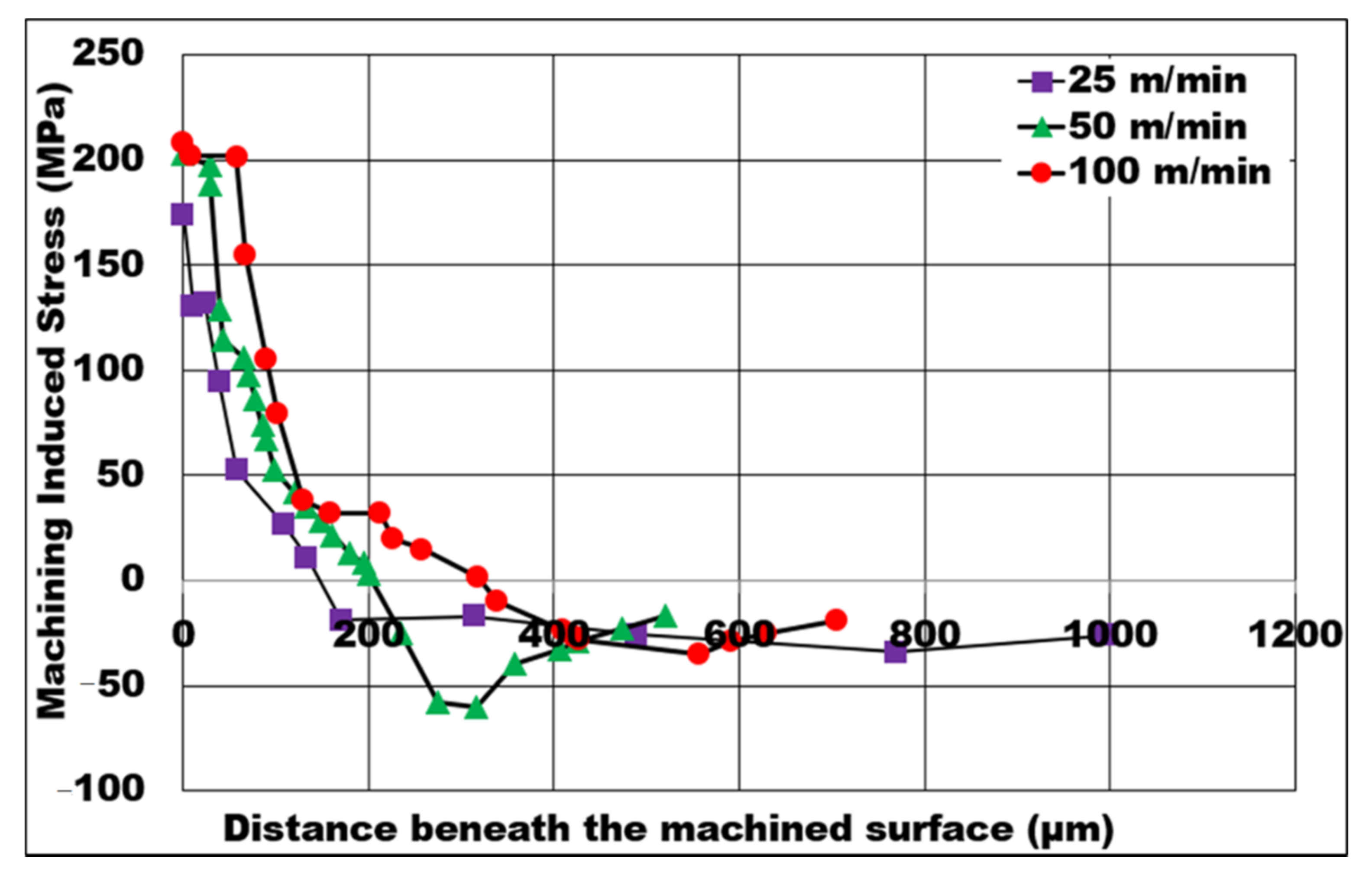
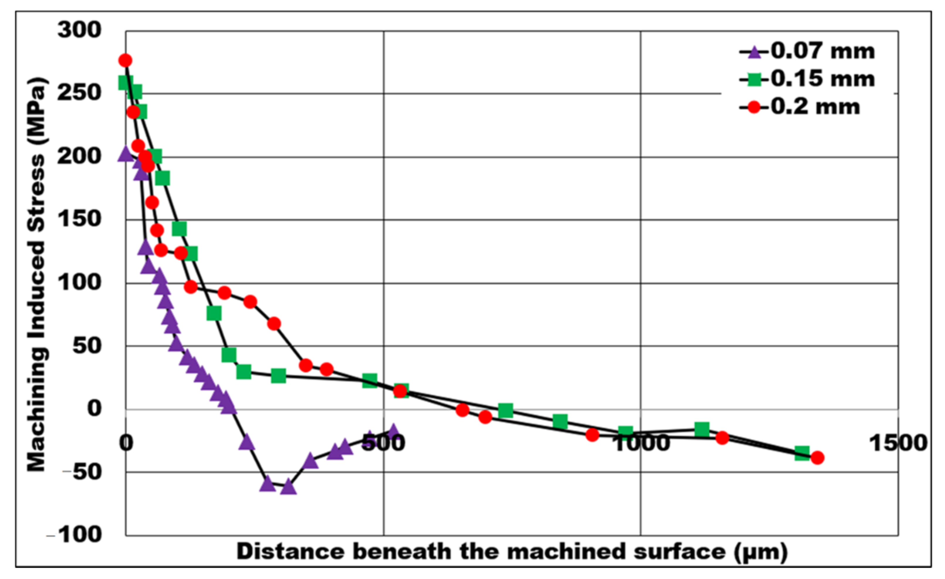
3.2. Effect of the Process Parameters on the Simulated Machining-Induced Stress

The machining process induces mechanical stresses beneath the cutting layer that are detrimental to the fatigue life of the component. Hence, it is of utmost importance that the pattern of these process-induced stresses is mapped and analyzed. Depending on the application, stress may negatively or positively improve a product’s performance. In this paper, the effects of the process parameters on the simulated machining-induced stress were predicted using FE simulation, and their pattern was analyzed. The depth of machining-induced tensile stress will definitely influence the fatigue life of the machined foam parts. As machining sometimes generates undesirable tensile-induced machining stress, it is crucial to understand how the process parameters affect the depth of simulated machining-induced tensile stress. In Figure 8, Figure 9 and Figure 10, the tensile stress was initially distributed on the cutting layer, which was approximately 100 μm deep, and changed to compressive stress at a certain distance beneath the machined surface.
Figure 8 shows the effect of the cutting speed on the simulated machining-induced stress during orthogonal machining of 6061 aluminum-based syntactic foams. With an increase in the cutting speed, the material experienced higher temperatures at the primary and secondary shear zones. Subsequently, the chip compression ratio decreased as the cutting tool sheared a less work-hardened matrix due to a higher temperature. This high heat generation focused on the work material reduced the average shear forces, the maximum shear stress, and the work hardening tendency of the material. The simulations showed the machining-induced stress to be of tensile nature on the machined surface to a depth that was higher at higher cutting speeds. The cutting-induced stress on the machined surface was minimum (173.948 MPa) at the lowest cutting speed, making it favorable to the workpiece due to low depth of tensile stress distribution. It was noted that the depth of the simulated machining-induced tensile stresses decreased with a decreasing cutting speed. The machining-induced stress depth condition was detrimental at a corresponding primary shear zone temperature of 193 °C, which was recorded at the cutting speed of 100 m/min. This trend agrees with the decrease in cutting force owing to thermal softening of the 6061 aluminum matrix with an increasing cutting speed.
Figure 9 highlights the influence of uncut chip thickness on the simulated machining-induced stresses. With the increase in uncut chip thickness, a greater number of hollow alumina shells came in contact with the rake face of the tool, giving rise to an increased friction force. Subsequently, a surge of temperature in the primary and secondary shear zones was accompanied by a reduced chip compression ratio. As a result, the induced tensile stress magnitude and depth on the machined surface increased, which turned out to be detrimental to the workpiece. The machining-induced tensile stress on the machined surface was minimum (202.88 MPa) in lower uncut chip thickness conditions, which were favorable for this material. An increase in chip load caused an increase in the energy consumed for the plastic deformation of the matrix. It was noted that, as the uncut chip thickness increased, the simulated machining-induced tensile stress distribution increased along with the depth on the machined surface. At a higher uncut chip thickness, a greater number of shells enhanced matrix hardening. This phenomenon promoted matrix plastic deformation by the shearing force. The favorable conditions to increase the compressive nature of machining-induced stress were identified at lower uncut chip thickness values for a given cutting speed.
Figure 10 shows the distribution of simulated machining-induced stress influenced by the average size of the hollow alumina shells for a 10% volume fraction. As the size of hollow alumina shell became coarser, the number of shells in the matrix was reduced for a given volume fraction, which lessened the number of shell contacts with the rake face of the tool. Moreover, there could be reduced pinning of matrix plastic flow by the hollow shells. Therefore, the average shear force and maximum shear stress were reduced, as noted in the simulation. Subsequently, the depth of machining-induced tensile stress distribution increased. At 10% volume fraction of hollow alumina shell reinforcements, the magnitude of simulated tensile stress on the machined surface was found to be predominantly tensile in nature up to a depth of approximately 100 μm beneath the machined surface in both cases. It was noted that finer the average size of the hollow shells, the more compressive was the nature of the machining-induced stress.

4. Conclusions

This paper presented a machining FE simulation model for 6061 aluminum closed cell syntactic foams using the AdvantEdgeTM FE software. The key conclusions of this study are:
  • An increase in the cutting speed resulted in a reduction of the cutting forces by at least 33%, primarily due to thermal softening of the matrix as indicated by the temperature distribution contours. Therefore, the magnitude of machining-induced tensile stresses on the cutting layer increased by 20%.
  • Machining at higher uncut chip thickness resulted in an increase of the machining force by almost 140%, leading to an increase in machining-induced stress values by 35%.
  • The higher the volume fraction of hollow alumina shells and the finer the shell diameter, the higher the magnitude of the cutting forces. A higher machining-induced stress depth was recorded for syntactic foams with coarser alumina shells.
  • A favorable compressive stress distribution in the machined layer was obtained while machining at lower cutting speed and uncut chip thickness values for a volume fraction of 10% hollow alumina shell reinforcements.

Author Contributions

Conceptualization, S.K.; Formal analysis, K.T.; Investigation, K.T.; Methodology, M.N.; Validation, S.P.; Writing—review & editing, S.P. and R.K. All authors have read and agreed to the published version of the manuscript.

Funding

American University of Sharjah: Research Grant (FRG21-M-E88).

Institutional Review Board Statement

Not applicable.

Informed Consent Statement

Not applicable.

Data Availability Statement

The data presented in this study are available on request from corresponding author.

Acknowledgments

The authors would like to acknowledge the financial support of the American University of Sharjah, UAE, Research Grant (FRG21-M-E88). Thanks to Dennis Pusing for help with the machining trials and to Venkat Raghavan (SwamEquip India) for manufacturing the billets.

Conflicts of Interest

The authors declare no conflict of interest.

References

  1. Movahedi, N.; Murch, G.E.; Belova, I.V.; Fiedler, T. Manufacturing and compressive properties of tube-filled metal syntactic foams. J. Alloys Compd. 2020, 822, 153465. [Google Scholar] [CrossRef]
  2. Orbulov, I.N.; Szlancsik, A.; Kemény, A.; Kincses, D. Compressive mechanical properties of low-cost, aluminium matrix syntactic foams. Compos. Part A Appl. Sci. Manuf. 2020, 135, 105923. [Google Scholar] [CrossRef]
  3. Fragoso-Medina, O.; Velázquez-Villegas, F. Aluminum foam to improve crash safety performance: A numerical simulation approach for the automotive industry. Mech. Based Des. Struct. Mach. 2021. [Google Scholar] [CrossRef]
  4. Orbulov, I.N.; Kemény, A.; Filep, Á.; Gácsi, Z. Compressive characteristics of bimodal aluminium matrix syntactic foams. Compos. Part A Appl. Sci. Manuf. 2019, 124, 105479. [Google Scholar] [CrossRef] [Green Version]
  5. Thiyagarajan, R.; Kumar, M.S. A Review on Closed Cell Metal Matrix Syntactic Foams: A Green Initiative towards Eco-Sustainability. Mater. Manuf. Process. 2021, 36, 1333–1351. [Google Scholar] [CrossRef]
  6. Samvatsar, K.; Dave, H. A comprehensive study on using fly ash as reinforcement material in aluminium and magnesium based syntactic foams. Mater. Today Proc. 2021, 47, 2384–2390. [Google Scholar] [CrossRef]
  7. Shukla, A.K.; Mondal, D.P.; Dutta Majumdar, J. Metallurgical Characteristics, Compressive Strength, and Chemical Degradation Behavior of Aluminum-Cenosphere Composite Foam Developed by Spray Forming Route. J. Mater. Eng. Perform. 2021, 30, 5750–5762. [Google Scholar] [CrossRef]
  8. Bolat, Ç.; Akgün, İ.C.; Göksenli, A. On the Way to Real Applications: Aluminum Matrix Syntactic Foams. Eur. Mech. Sci. 2020, 4, 131–141. [Google Scholar] [CrossRef]
  9. Su, M.; Wang, H.; Hao, H.; Fiedler, T. Compressive properties of expanded glass and alumina hollow spheres hybrid reinforced aluminum matrix syntactic foams. J. Alloys Compd. 2020, 821, 153233. [Google Scholar] [CrossRef]
  10. Bolat, Ç.; Ergene, B.; Karakılınç, U.; Gökşenli, A. Investigating on the machinability assessment of precision machining pumice reinforced AA7075 syntactic foam. Proc. Inst. Mech. Eng. Part C J. Mech. Eng. Sci. 2021. [Google Scholar] [CrossRef]
  11. Kannan, S.; Kishawy, H.A.; Pervaiz, S.; Thomas, K.; Karthikeyan, R.; Arunachalam, R. Machining of novel AA7075 foams containing thin-walled ceramic bubbles. Mater. Manuf. Process. 2020, 35, 1812–1821. [Google Scholar] [CrossRef]
  12. Kannan, S.; Pervaiz, S.; Klassen, R.J.; Huo, D.; Haghshenas, M. An energy-based analysis for machining novel AZ91 magnesium composite foam dispersed with ceramic microspheres. J. Manuf. Sci. Eng. Trans. ASME 2021, 143, 031007. [Google Scholar] [CrossRef]
  13. Kannan, S.; Pervaiz, S.; Alhourani, A.; Klassen, R.J.; Selvam, R.; Haghshenas, M. On the role of hollow aluminium oxide microballoons during machining of AZ31 magnesium syntactic foam. Materials 2020, 13, 3534. [Google Scholar] [CrossRef] [PubMed]
  14. Ullen, N.B. Characterization of machinability of sintered steel foams having different porosities during drilling operations. Mach. Sci. Technol. 2020, 25, 527–557. [Google Scholar] [CrossRef]
  15. Guerra-Silva, R.; Teicher, U.; Ihlenfeldt, S.; González-Zamora, A. Finite element analysis of orthogonal cutting of cellular metals: Influence of cutting conditions on chip formation and surface damage. Int. J. Adv. Manuf. Technol. 2021, 113, 1267–1280. [Google Scholar] [CrossRef]
  16. Rajendran, A.M.; Grove, D.J. Modeling of shock and impact behaviors of aluminum oxide. Trans. Built Environ. 1998, 32, 447–460. [Google Scholar]
  17. Ghandehariun, A.; Nazzal, M.; Kishawy, H.A.; Umer, U. On modeling the deformations and tool-workpiece interactions during machining metal matrix composites. Int. J. Adv. Manuf. Technol. 2017, 91, 1507–1516. [Google Scholar] [CrossRef]
  18. Aluminum 6061-T6; 6061-T651. Available online: http://www.matweb.com/search/datasheet_print.aspx?matguid=1b8c06d0ca7c456694c7777d9e10be5b (accessed on 18 April 2021).
  19. Blau, P.J. Wear of Materials; Elsevier: Amsterdam, The Netherlands, 2003; ISBN 978-0-08-044301-0. [Google Scholar]
  20. Kurlov, A.S.; Gusev, A.I. Tungsten Carbides: Structure, Properties and Application in Hardmetals; Springer: Berlin/Heidelberg, Germany, 2013; Volume 184. [Google Scholar] [CrossRef]
  21. Koklu, U. The Drilling Machinability of 5083 Aluminum Under Shallow and Deep Cryogenic Treatment. Emerg. Mater. Res. 2020, 9, 323–330. [Google Scholar] [CrossRef]
  22. Koklu, U.; Kayhanlar, H. An Experimental Investigation on Machinability of AZ31B Magnesium Alloy under Dry and Dipped Cryogenic Approaches. J. Mater. Eng. Perform. 2022, 31, 1285–1296. [Google Scholar] [CrossRef]
  23. Köklü, U.; Koçar, O.; Morkavuk, S.; Giasin, K.; Ayer, Ö. Influence of extrusion parameters on drilling machinability of AZ31 magnesium alloy. Proc. Inst. Mech. Eng. Part E J. Process Mech. Eng. 2022. [Google Scholar] [CrossRef]
Figure 1. Boundary conditions for workpiece and cutting tool chosen for the FE model in AdvantEdgeTM.
Metals 12 00596 g001
Figure 2. (a) Stress–strain compression behavior of the 6061 aluminum syntactic foam and (b) compression test set-up.
Metals 12 00596 g002
Figure 3. (a) Machining set-up, (b) sample cutting force trace collected from the tests, (c) representative machined chip.
Metals 12 00596 g003
Figure 4. (a) Effect of the variation of the cutting velocity on machining forces (AdvantEdgeTM simulation); 6061/hollow alumina shell syntactic foams (vol% = 10%, h = 0.07 mm, b = 3 mm, dry cut); Von Mises Stress contour at (b) 100 m/min and (c) 25 m/min; temperature contour at (d) 100 m/min and (e) 25 m/min.
Metals 12 00596 g004
Figure 5. (a) Effect of undeformed chip thickness of 6061/hollow alumina shell syntactic foams on machining forces (AdvantEdgeTM simulation) (vol% = 10%, Vc = 50 m/min, b = 3 mm); Von Mises stress contour at (b) h = 0.07 mm and (c) h = 0.2 mm.
Metals 12 00596 g005
Figure 6. (a) Numerical friction prediction values from the 2D-FE model and (b) predicted peak temperature distribution for 6061/hollow alumina syntactic foams (AdvantEdgeTM) (vol% = 10%, Vc = 50 m/min, Dry cut).
Metals 12 00596 g006
Figure 7. (a) Effect of reinforcement volume percentage on machining force (AdvantEdgeTM simulation); 6061/hollow alumina shell syntactic foams (Vc = 50 m/min, h = 0.07 mm); Von Mises stress contour (b) 10% hollow alumina and (c) 20% hollow alumina.
Metals 12 00596 g007
Figure 8. FE simulation of the effect of the cutting speed on machining-induced stress when cutting 10% volume fraction syntactic foam (uncut chip thickness = 0.07 mm).
Metals 12 00596 g008
Figure 9. FE simulation of the effect of uncut chip thickness on machining-induced stress for 10% volume fraction syntactic foam (Vc = 50 m/min).
Metals 12 00596 g009
Figure 10. FE simulation of the effect of the average size of hollow alumina shells on the machining-induced stress for 10% volume fraction syntactic foam (Vc = 50 m/min, uncut chip thickness = 0.07 mm).
Metals 12 00596 g010
Table 1. Chemical composition of the 6061 aluminum-based syntactic foam (supplier data).
Chemical Composition of 6061 Aluminum in Weight (%)
AlCrCuFeSiMgMnZn
95.8–98.60.04–0.350.15–0.40.70.41.50.10.25
Chemical Composition of the Hollow Alumina Shell in Weight (%)
Al2O3Fe2O3CaOSiO2Na2O
99.70.0030.010.0250.26
Table 2. Physical and mechanical properties of the hollow alumina shell and 6061 matrix [16,17,18].
Hollow Alumina Shell
Physical Properties
Bulk Density (g/cm3)Average Porosity (%)Average Wall Thickness (μm)Average Bubble Size (mm)Bubble vol%Thermal Conductivity (W m−1K−1)
1.8830.04–0.080.3–0.610%, 20%1.5
Mechanical Properties
Crush Strength (MPa)Poisson’s Ratio
120   ± 100.231
6061 Matrix
Physical Properties
Density (g/cm3)Thermal Conductivity (W m−1K−1)Specific Heat (J kg−1K−1)
2.7165896
Mechanical Properties
Poisson RatioCompressive Strength (MPa)Yield Strength (MPa)Young’s Modulus (GPa)
0.3325015068
Table 3. Properties of the cutting tool [19,20].
Thermal Conductivity (W m−1K−1)Coefficient of Thermal Expansion (1/K)Young’s Modulus (GPa)Poisson’s RatioDensity (g/cm3)Specific Heat (J kg−1K−1)
1105.5 × 10−67000.3115.639.8
Table 4. Machining factors for 6061-based syntactic foams.
Matrix6061 aluminum
ReinforcementHollow alumina thin-walled shell
ToolCarbide-coated insert from SandvikTM
Rake angle and clearance angle6° and 7°
Cutting speed (m/min)25, 50, 100
Undeformed Chip Thickness (mm)0.02, 0.07, 0.15, 0.2
Volume fraction of hollow microsphere10%, 20%
Average size of hollow microsphere (mm)0.1–0.5 mm, 0.5–1 mm
Width of cut (mm)3
LubricationDry
Publisher’s Note: MDPI stays neutral with regard to jurisdictional claims in published maps and institutional affiliations.

