
Use of Low Melting Point Metals and Alloys (Tm < 420 °C) as Phase Change Materials: A Review


Abstract
:1. Introduction
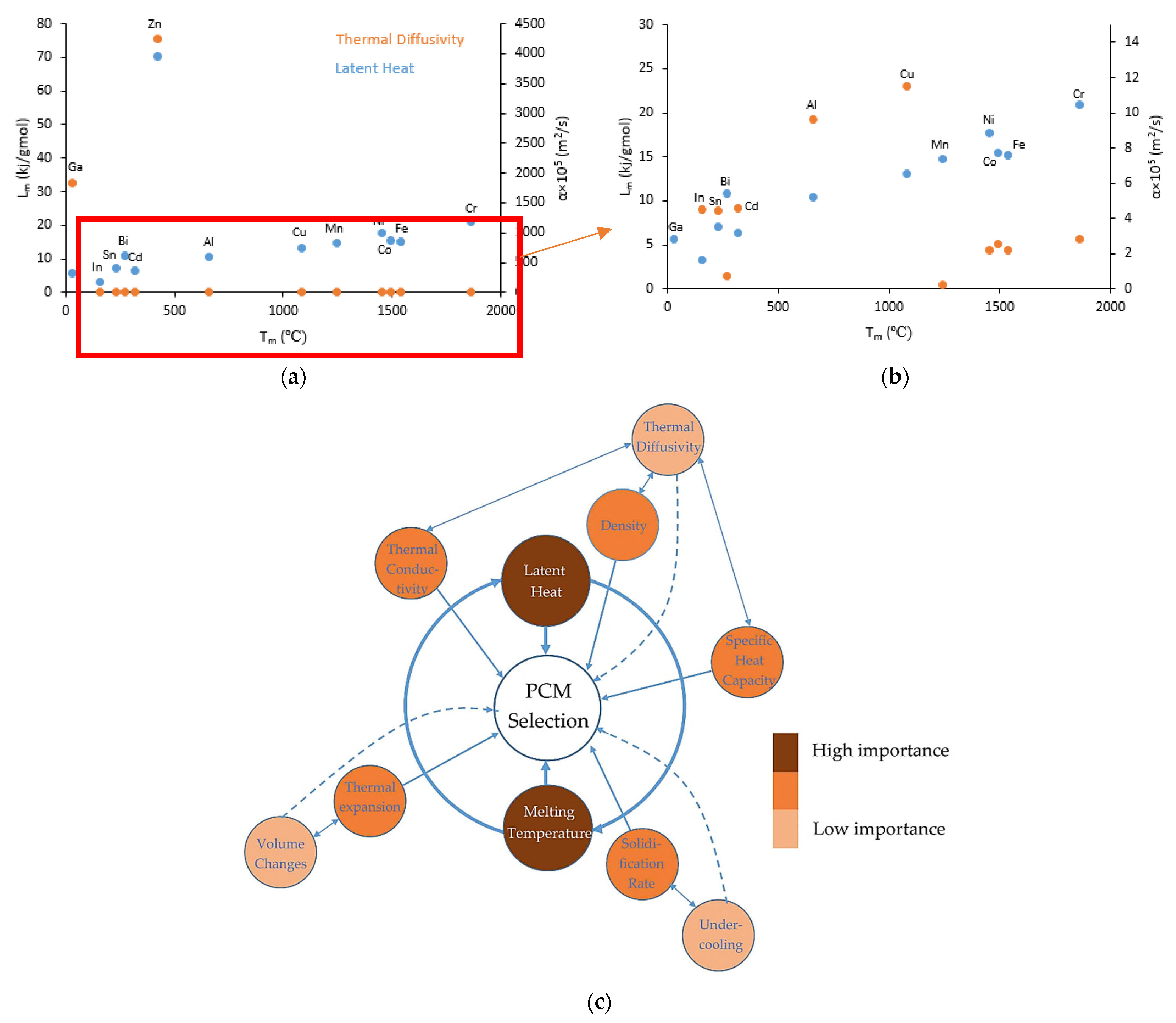
2. Criteria for PCM Selection
- Melting temperature of PCM driven by the required service temperature.
- High latent heat and suitable specific heat. The former controls the volume and thermal density storage of the PCM, and the latter controls the rate of temperature change of the PCM before reaching the transition temperature.
- High thermal conductivity enables high discharge capacity of the PCM. This characteristic led PCMs to be used in buildings to take less time to store/release energy.
- High density to reduce the required volume of the PCM.
- Low thermal expansion and low vapor pressure to avoid damaging the container and to avoid residual stress in the solid surroundings.
- Reversibility of the transition.
- Low solidification undercooling and high solidification rate as they affect the transition kinetic.
- Non-toxicity, non-flammability and non-reactivity with the container.
- Availability and affordability.
3. Application of Metallic PCMs
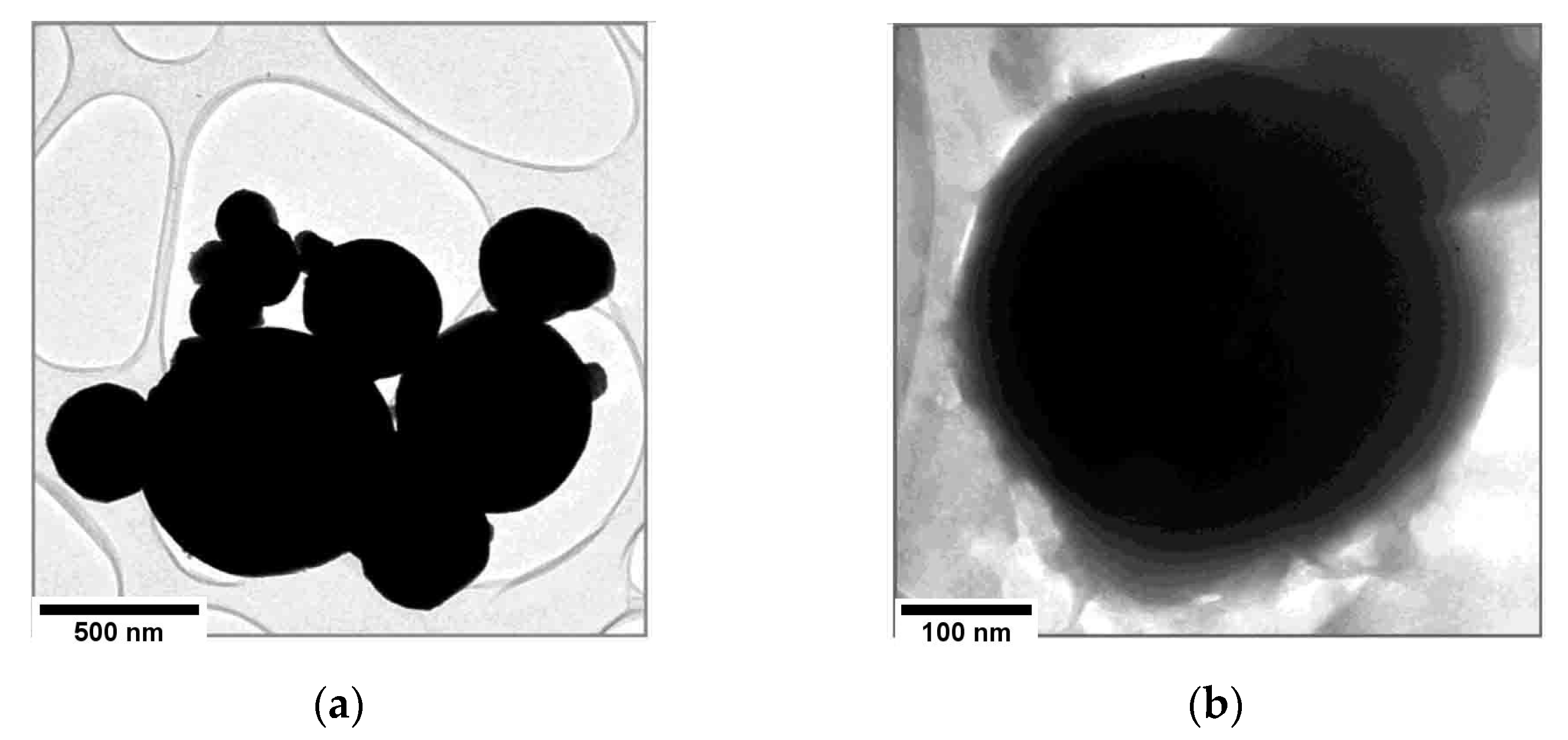
4. Encapsulation of PCMs
- Chemical stability. The capsule should react with neither the metallic PCMs nor the surrounding matrix. It should have close to zero solubility with the PCM and the matrix. Such reactions may result in corrosion of the capsule, contamination of the PCM or the matrix, leakage of PCM or formation of undesirable intermetallic phases at the interface. These will affect such thermal properties as the melting point, heat transfer coefficient and latent heat of the PCM.
- Thermal and mechanical stability. The capsule should have high thermal resistance, appropriate coefficient of thermal expansion and be dense and stable during solid/liquid transition to overcome the stresses induced by repeated expansion/contraction of the PCM. This will prevent capsule cracking and PCM leakage during thermal cycling.
- Large coefficient of heat transfer and small heat capacity.
- Small coefficient of thermal expansion (CTE) and enough space for melting and solidification of the PCM.
- Oxidation resistance for high-temperature applications.
- High specific contact area.
- Nontoxicity, availability and affordability.
5. Pure Metal-Based PCMs
5.1. Pure Zinc
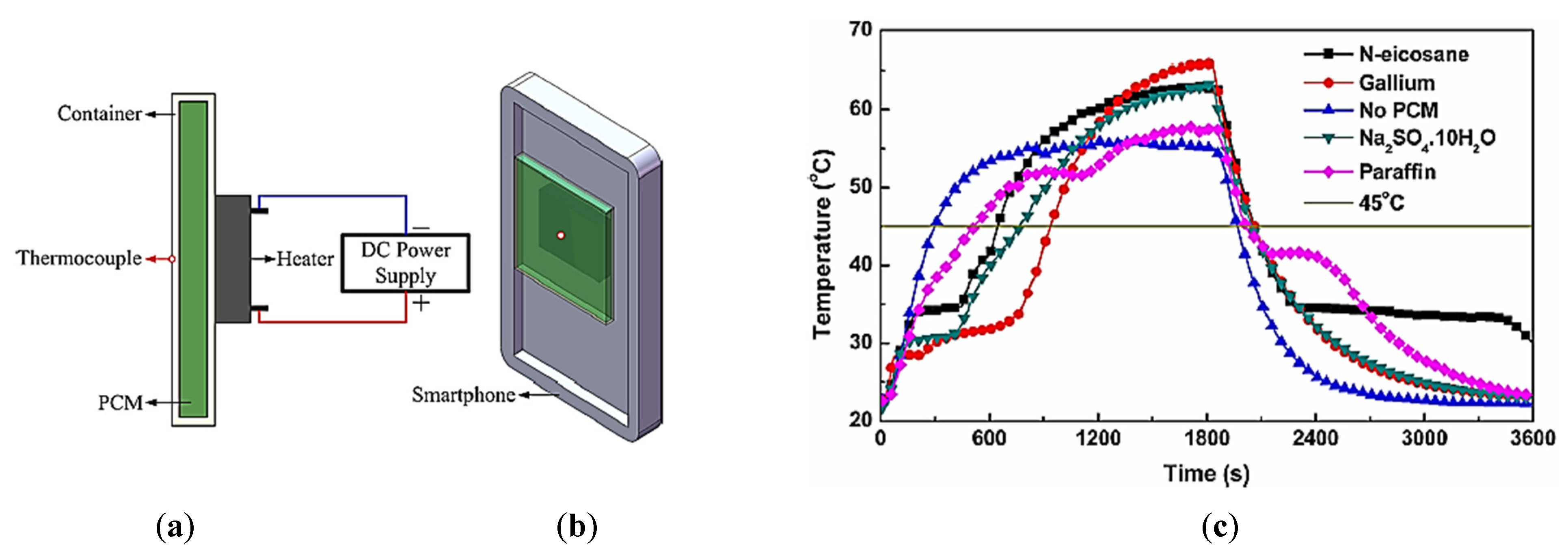
5.2. Pure Gallium
- High thermal conductivity, which improves the heat transfer required for cooling systems;
- Low specific heat capacity, which reduces the delay time for melting of the PCM, which in turn shortens the time required for keeping the CPU at constant temperatures;
- Low volume change.
5.3. Pure Tin
6. Metallic Alloys as PCM
6.1. Binary Alloys
6.2. Ternary Alloys
6.3. Quarterly Alloys
7. Metal Matrix Composite PCMs
8. Miscibility Gap Alloys (MGAs) as a New Generation of PCMs
- In low-temperature systems, the phase change temperature is less than 300 °C. These MGAs can be used in waste heat recovery and space heating. For example, Sn 50%-Al with a 230 °C phase change temperature (the melting point of Sn as the active phase) is in this category [87].
- High-temperature systems where the phase change temperature is between 500 and 750 °C. Such systems are appropriate for the generation of steam in dish CSPs. A suitable PCM for this application is Mg 50%-Fe with a 650 melting temperature [87].
9. Innovative Application of Metallic PCMs
10. Conclusions and Outlook
Author Contributions
Funding
Data Availability Statement
Conflicts of Interest
References
- Yang, L.; Jin, X.; Zhang, Y.; Du, K. Recent Development on Heat Transfer and Various Applications of Phase-Change Materials. J. Clean. Prod. 2021, 287, 124432. [Google Scholar] [CrossRef]
- Mohamed, S.A.; Al-Sulaiman, F.A.; Ibrahim, N.I.; Zahir, M.H.; Al-Ahmed, A.; Saidur, R.; Yılbaş, B.S.; Sahin, A.Z. A Review on Current Status and Challenges of Inorganic Phase Change Materials for Thermal Energy Storage Systems. Renew. Sustain. Energy Rev. 2017, 70, 1072–1089. [Google Scholar] [CrossRef]
- Confalonieri, C.; Grimaldi, A.T.; Gariboldi, E. Ball-Milled Al–Sn Alloy as Composite Phase Change Material. Mater. Today Energy 2020, 17, 100456. [Google Scholar] [CrossRef]
- Sharma, R.K.; Ganesan, P.; Tyagi, V.V.; Metselaar, H.S.C.; Sandaran, S.C. Developments in Organic Solid–Liquid Phase Change Materials and Their Applications in Thermal Energy Storage. Energy Convers. Manag. 2015, 95, 193–228. [Google Scholar] [CrossRef] [Green Version]
- Salunkhe, P.B.; Shembekar, P.S. A Review on Effect of Phase Change Material Encapsulation on the Thermal Performance of a System. Renew. Sustain. Energy Rev. 2012, 16, 5603–5616. [Google Scholar] [CrossRef]
- Ge, H.; Li, H.; Mei, S.; Liu, J. Low Melting Point Liquid Metal as a New Class of Phase Change Material: An Emerging Frontier in Energy Area. Renew. Sustain. Energy Rev. 2013, 21, 331–346. [Google Scholar] [CrossRef]
- Milián, Y.E.; Gutiérrez, A.; Grágeda, M.; Ushak, S. A Review on Encapsulation Techniques for Inorganic Phase Change Materials and the Influence on Their Thermophysical Properties. Renew. Sustain. Energy Rev. 2017, 73, 983–999. [Google Scholar] [CrossRef]
- Akgün, M.; Aydin, O.; Kaygusuz, K. Experimental Study on Melting/Solidification Characteristics of a Paraffin as PCM. Energy Convers. Manag. 2007, 48, 669–678. [Google Scholar] [CrossRef]
- Raud, R.; Jacob, R.; Bruno, F.; Will, G.; Steinberg, T.A. A Critical Review of Eutectic Salt Property Prediction for Latent Heat Energy Storage Systems. Renew. Sustain. Energy Rev. 2017, 70, 936–944. [Google Scholar] [CrossRef] [Green Version]
- Liu, M.; Saman, W.; Bruno, F. Review on Storage Materials and Thermal Performance Enhancement Techniques for High Temperature Phase Change Thermal Storage Systems. Renew. Sustain. Energy Rev. 2012, 16, 2118–2132. [Google Scholar] [CrossRef]
- Nazir, H.; Batool, M.; Bolivar, F.J.; Isaza-ruiz, M.; Xu, X.; Vignarooban, K.; Phelan, P.; Kannan, A.M. Recent Developments in Phase Change Materials for Energy Storage Applications: A Review. Int. J. Heat Mass Transf. 2019, 129, 491–523. [Google Scholar] [CrossRef]
- Heinz, A.; Streicher, W. Application of Phase Change Materials and PCM-Slurries for Thermal Energy Storage. In Proceedings of the ECOSTOC Conference, Session 12B–Transportation of Energy, Galloway Township, NJ, USA, 31 May–2 June 2006; Citeseer: Princeton, NJ, USA, 2006. [Google Scholar]
- Lafdi, K.; Mesalhy, O.; Elgafy, A. Graphite Foams Infiltrated with Phase Change Materials as Alternative Materials for Space and Terrestrial Thermal Energy Storage Applications. Carbon 2007, 46, 159–168. [Google Scholar] [CrossRef]
- Mahdi, J.M.; Nsofor, E.C. Multiple-Segment Metal Foam Application in the Shell-and-Tube PCM Thermal Energy Storage System. J. Energy Storage 2018, 20, 529–541. [Google Scholar] [CrossRef]
- Lazzarin, R.; Noro, M.; Righetti, G.; Mancin, S. Application of Hybrid PCM Thermal Energy Storages with and without Al Foams in Solar Heating/Cooling and Ground Source Absorption Heat Pump Plant: An Energy and Economic Analysis. Appl. Sci 2019, 9, 1007. [Google Scholar] [CrossRef] [Green Version]
- Choi, D.H.; Lee, J.; Hong, H.; Kang, Y.T. Thermal Conductivity and Heat Transfer Performance Enhancement of Phase Change Materials (PCM) Containing Carbon Additives for Heat Storage Application. Int. J. Refrig. 2014, 42, 112–120. [Google Scholar] [CrossRef]
- Krishna, J.; Kishore, P.S.; Solomon, A.B. Heat Pipe with Nano Enhanced-PCM for Electronic Cooling Application. Exp. Therm. Fluid Sci. 2017, 81, 84–92. [Google Scholar] [CrossRef] [Green Version]
- Sakai, H.; Sheng, N.; Kurniawan, A.; Akiyama, T.; Nomura, T. Fabrication of Heat Storage Pellets Composed of Microencapsulated Phase Change Material for High-Temperature Applications. Appl. Energy 2020, 265, 114673. [Google Scholar] [CrossRef]
- Wang, Z.; Wang, H.; Yang, M.; Sun, W.; Yin, G.; Zhang, Q.; Ren, Z. Thermal Reliability of Al-Si Eutectic Alloy for Thermal Energy Storage. Mater. Res. Bull. 2017, 95, 300–306. [Google Scholar] [CrossRef]
- Noohi, Z.; Niroumand, B.; Timelli, G. Numerical Simulation of the Effects of a Phase Change Material (PCM) on Solidification Path of Gravity Sand Cast Al-Cu Alloy. La Metallurgia Italiana 2021, 25–30. [Google Scholar]
- Confalonieri, C.; Gariboldi, E. Al-Sn Miscibility Gap Alloy Produced by Power Bed Laser Melting for Application as Phase Change Material. J. Alloys Compd. 2021, 881, 160596. [Google Scholar] [CrossRef]
- Costa, S.C.; Kenisarin, M. A Review of Metallic Materials for Latent Heat Thermal Energy Storage: Thermophysical Properties, Applications, and Challenges. Renew. Sustain. Energy Rev. 2022, 154. [Google Scholar] [CrossRef]
- Cárdenas, B.; León, N. High Temperature Latent Heat Thermal Energy Storage: Phase Change Materials, Design Considerations and Performance Enhancement Techniques. Renew. Sustain. Energy Rev. 2013, 27, 724–737. [Google Scholar] [CrossRef]
- Fairbrother, F. Metals Reference Book; Elsevier: Amsterdam, The Netherlands, 1977; Volume 51, ISBN 1483192520. [Google Scholar]
- Waqas, A.; Din, Z.U. Phase Change Material (PCM) Storage for Free Cooling of Buildings—A Review. Renew. Sustain. Energy Rev. 2013, 18, 607–625. [Google Scholar] [CrossRef]
- Xu, H.; Sze, J.Y.; Romagnoli, A.; Py, X. Selection of Phase Change Material for Thermal Energy Storage in Solar Air Conditioning Systems. Energy Procedia 2017, 105, 4281–4288. [Google Scholar] [CrossRef]
- Rathod, M.K.; Kanzaria, H.V. A Methodological Concept for Phase Change Material Selection Based on Multiple Criteria Decision Analysis with and without Fuzzy Environment. Mater. Des. 2011, 32, 3578–3585. [Google Scholar] [CrossRef]
- Rea, J.E.; Toberer, E.S.; Siegel, N.P. Guidelines for Phase Change Material Selection Based on a Holistic System Model. Sol. Energy Mater. Sol. Cells 2020, 208, 110422. [Google Scholar] [CrossRef]
- Anilkumar, B.C.; Maniyeri, R.; Anish, S. Optimum Selection of Phase Change Material for Solar Box Cooker Integrated with Thermal Energy Storage Unit Using Multi-Criteria Decision-Making Technique. J. Energy Storage 2021, 40, 102807. [Google Scholar] [CrossRef]
- Dhanalakshmi, C.S.; Madhu, P.; Karthick, A.; Mathew, M.; Vignesh Kumar, R. A Comprehensive MCDM-Based Approach Using TOPSIS and EDAS as an Auxiliary Tool for Pyrolysis Material Selection and Its Application. Biomass Convers. Biorefin. 2020, 121, 237–253. [Google Scholar] [CrossRef]
- Yang, K.; Zhu, N.; Chang, C.; Wang, D.; Yang, S.; Ma, S. A Methodological Concept for Phase Change Material Selection Based on Multi-Criteria Decision Making (MCDM): A Case Study. Energy 2018, 165, 1085–1096. [Google Scholar] [CrossRef]
- Jeon, J.; Lee, J.H.; Seo, J.; Jeong, S.G.; Kim, S. Application of PCM Thermal Energy Storage System to Reduce Building Energy Consumption. J. Therm. Anal. Calorim. 2013, 111, 279–288. [Google Scholar] [CrossRef]
- Xie, J.; Wang, W.; Liu, J.; Pan, S. Thermal Performance Analysis of PCM Wallboards for Building Application Based on Numerical Simulation. Sol. Energy 2018, 162, 533–540. [Google Scholar] [CrossRef]
- Sharif, M.K.A.; Al-Abidi, A.A.; Mat, S.; Sopian, K.; Ruslan, M.H.; Sulaiman, M.Y.; Rosli, M.A.M. Review of the Application of Phase Change Material for Heating and Domestic Hot Water Systems. Renew. Sustain. Energy Rev. 2015, 42, 557–568. [Google Scholar] [CrossRef]
- Deng, Y.-G.; Liu, J. Corrosion Development between Liquid Gallium and Four Typical Metal Substrates Used in Chip Cooling Device. Appl. Phys. A 2009, 95, 907–915. [Google Scholar] [CrossRef]
- Liu, J.; Zhou, Y.X.; Lv, Y.G.; Li, T. Liquid Metal Based Miniaturized Chip-Cooling Device Driven by Electromagnetic Pump. Am. Soc. Mech. Eng. Electron. Photonic Packag. EPP 2005, 5, 501–510. [Google Scholar] [CrossRef]
- Prieto, C.; Cabeza, L.F. Thermal Energy Storage (TES) with Phase Change Materials (PCM) in Solar Power Plants (CSP). Concept and Plant Performance. Appl. Energy 2019, 254, 113646. [Google Scholar] [CrossRef]
- Wang, G.; Shi, H.; Lotnyk, A.; Shi, D.; Wang, R. Conversion of p–n Conduction Type by Spinodal Decomposition in Zn-Sb-Bi Phase-Change Alloys. NPG Asia Mater. 2020, 12, 17. [Google Scholar] [CrossRef] [Green Version]
- Wuttig, M.; Yamada, N. Phase-Change Materials for Rewriteable Data Storage. Nat. Mater. 2007, 6, 824–832. [Google Scholar] [CrossRef]
- Jung, Y.; Lee, S.-H.; Ko, D.-K.; Agarwal, R. Synthesis and Characterization of Ge2Sb2Te5 Nanowires with Memory Switching Effect. J. Am. Chem. Soc. 2006, 128, 14026–14027. [Google Scholar] [CrossRef]
- Han, N.; Kim, S.I.; Yang, J.; Lee, K.; Sohn, H.; So, H.; Ahn, C.W.; Yoo, K. Phase-change Memory in Bi2Te3 Nanowires. Adv. Mater. 2011, 23, 1871–1875. [Google Scholar] [CrossRef]
- Su, W.; Darkwa, J.; Kokogiannakis, G. Review of Solid-Liquid Phase Change Materials and Their Encapsulation Technologies. Renew. Sustain. Energy Rev. 2015, 48, 373–391. [Google Scholar] [CrossRef]
- Zhao, W.; Neti, S.; Oztekin, A. Heat Transfer Analysis of Encapsulated Phase Change Materials. Appl. Therm. Eng. 2013, 50, 143–151. [Google Scholar] [CrossRef]
- Pielichowska, K.; Pielichowski, K. Phase Change Materials for Thermal Energy Storage. Prog. Mater. Sci. 2014, 65, 67–123. [Google Scholar] [CrossRef]
- Bao, J.; Zou, D.; Zhu, S.; Ma, Q.; Wang, Y.; Hu, Y. A Medium-Temperature, Metal-Based, Microencapsulated Phase Change Material with a Void for Thermal Expansion. Chem. Eng. J. 2021, 415, 128965. [Google Scholar] [CrossRef]
- Blaney, J.J.; Neti, S.; Misiolek, W.Z.; Oztekin, A. Containment Capsule Stresses for Encapsulated Phase Change Materials. Appl. Therm. Eng. 2013, 50, 555–561. [Google Scholar] [CrossRef]
- Sabol, J.C.; Misiolek, W.Z.; Oztekin, A.; Neti, S. Characterization of Intermediate Phases Formed Between Solid Nickel and Liquid Zinc During Use as an Encapsulated Phase Change Material in Solar Thermal Energy Storage Systems. Metallogr. Microstruct. Anal. 2012, 1, 208–216. [Google Scholar] [CrossRef] [Green Version]
- Zhao, W.; Zheng, Y.; Sabol, J.C.; Oztekin, A.; Neti, S.; Tuzla, K.; Misiolek, W.M.; Chen, J.C. Thermal Energy Storage Using Zinc as Encapsulated Phase Change Material. In Proceedings of the ASME International Mechanical Engineering Congress and Exposition, Denver, CO, USA, 11–17 November 2011; Volume 54907, pp. 849–856. [Google Scholar]
- Cingarapu, S.; Singh, D.; Timofeeva, E.V.; Moravek, M.R. Nanofluids with Encapsulated Tin Nanoparticles for Advanced Heat Transfer and Thermal Energy Storage. Int. J. Energy Res. 2014, 38, 51–59. [Google Scholar] [CrossRef]
- Navarrete, N.; Gimeno-Furio, A.; Mondragon, R.; Hernandez, L.; Cabedo, L.; Cordoncillo, E.; Julia, J.E. Nanofluid Based on Self-Nanoencapsulated Metal/Metal Alloys Phase Change Materials with Tuneable Crystallisation Temperature. Sci. Rep. 2017, 7, 17580. [Google Scholar] [CrossRef] [Green Version]
- Hsu, T.-H.; Chung, C.-H.; Chung, F.-J.; Chang, C.-C.; Lu, M.-C.; Chueh, Y.-L. Thermal Hysteresis in Phase-Change Materials: Encapsulated Metal Alloy Core-Shell Microparticles. Nano Energy 2018, 51, 563–570. [Google Scholar] [CrossRef]
- Valencia, J.J.; Quested, P.N. Thermophysical Properties. In Casting: ASM Handbook; ASM: Novelty, OH, USA, 2013. [Google Scholar]
- Ge, H.; Liu, J. Keeping Smartphones Cool With Gallium Phase Change Material. J. Heat Transfer 2013, 135, 054503. [Google Scholar] [CrossRef]
- Yang, X.H.; Tan, S.C.; Liu, J. Numerical Investigation of the Phase Change Process of Low Melting Point Metal. Int. J. Heat Mass Transf. 2016, 100, 899–907. [Google Scholar] [CrossRef]
- Lázaro, A.; Günther, E.; Mehling, H.; Hiebler, S.; Marín, J.M.; Zalba, B. Verification of a T-History Installation to Measure Enthalpy versus Temperature Curves of Phase Change Materials. Meas. Sci. Technol. 2006, 17, 2168–2174. [Google Scholar] [CrossRef]
- Rizvi, S.M.M.; Nayfeh, Y.; El Far, B.; Shin, D. Use of Silica Coated Zinc Nanoparticles for Enhancement in Thermal Properties of Carbonate Eutectic Salt for Concentrated Solar Power Plants. In Proceedings of the ASME 2020 14th International Conference on Energy Sustainability, ES 2020, Virtual, 17–18 June 2020; American Society of Mechanical Engineers: New York, NY, USA, 2020; Volume 83631, p. V001T08A006. [Google Scholar]
- Cingarapu, S.; Singh, D.; Timofeeva, E.V.; Moravek, M.R. Use of Encapsulated Zinc Particles in a Eutectic Chloride Salt to Enhance Thermal Energy Storage Capacity for Concentrated Solar Power. Renew. Energy 2015, 80, 508–516. [Google Scholar] [CrossRef] [Green Version]
- Song, S.; Shen, W.; Wang, J.; Wang, S.; Xu, J. Experimental Study on Laminar Convective Heat Transfer of Microencapsulated Phase Change Material Slurry Using Liquid Metal with Low Melting Point as Carrying Fluid. Int. J. Heat Mass Transf. 2014, 73, 21–28. [Google Scholar] [CrossRef]
- Ge, H.; Liu, J. Cooling Capacity of Metal Phase Change Material for Thermal Management of Mobile Phone Subject to Long Time Communication. In Proceedings of the ASME International Mechanical Engineering Congress and Exposition, San Diego, CA, USA, 15–21 November 2013; American Society of Mechanical Engineers: New York, NY, USA, 2013; Volume 56352, p. V08BT09A076. [Google Scholar]
- Malekan, M.; Khosravi, A.; Syri, S. Heat Transfer Modeling of a Parabolic Trough Solar Collector with Working Fluid of Fe3O4 and CuO/Therminol 66 Nanofluids under Magnetic Field. Appl. Therm. Eng. 2019, 163, 114435. [Google Scholar] [CrossRef]
- Sheng, N.; Lu, J.; Hu, J.; Zhu, R.; Fadillah, L.; Wang, C.; Zhu, C.; Rao, Z.; Habazaki, H. Synthesis of Sn@ SnO2 Core-Shell Microcapsules by a Self-Oxidation Strategy for Medium Temperature Thermal Storage. Chem. Eng. J. 2021, 420, 129906. [Google Scholar] [CrossRef]
- Lai, C.-C.; Chang, W.-C.; Hu, W.-L.; Wang, Z.M.; Lu, M.-C.; Chueh, Y.-L. A Solar-Thermal Energy Harvesting Scheme: Enhanced Heat Capacity of Molten HITEC Salt Mixed with Sn/SiO x Core–Shell Nanoparticles. Nanoscale 2014, 6, 4555–4559. [Google Scholar] [CrossRef]
- Lai, C.-C.; Lin, S.-M.; Chu, Y.-D.; Chang, C.-C.; Chueh, Y.-L.; Lu, M.-C. Tunable Endothermic Plateau for Enhancing Thermal Energy Storage Obtained Using Binary Metal Alloy Particles. Nano Energy 2016, 25, 218–224. [Google Scholar] [CrossRef]
- Zhu, S.; Nguyen, M.T.; Tokunaga, T.; Yonezawa, T. Size-Tunable Alumina-Encapsulated Sn-Based Phase Change Materials for Thermal Energy Storage. ACS Appl. Nano Mater. 2019, 2, 3752–3760. [Google Scholar] [CrossRef]
- Risueño, E.; Gil, A.; Rodríguez-Aseguinolaza, J.; Gil, A.; Tello, M.; Faik, A.; D’Aguanno, B. Thermal Cycling Testing of Zn–Mg–Al Eutectic Metal Alloys as Potential High-Temperature Phase Change Materials for Latent Heat Storage. J. Therm. Anal. Calorim. 2017, 129, 885–894. [Google Scholar] [CrossRef]
- Birchenall, C.E.; Riechman, A.F. Heat Storage in Eutectic Alloys. Metall. Trans. A 1980, 11, 1415–1420. [Google Scholar] [CrossRef]
- Farkas, D.; Birchenall, C.E. New Eutectic Alloys and Their Heats of Transformation. Metall. Trans. A 1985, 16, 323–328. [Google Scholar] [CrossRef]
- Adinberg, R.; Zvegilsky, D.; Epstein, M. Heat Transfer Efficient Thermal Energy Storage for Steam Generation. Energy Convers. Manag. 2010, 51, 9–15. [Google Scholar] [CrossRef]
- Blanco-Rodríguez, P.; Rodríguez-Aseguinolaza, J.; Risueño, E.; Tello, M. Thermophysical Characterization of Mg–51% Zn Eutectic Metal Alloy: A Phase Change Material for Thermal Energy Storage in Direct Steam Generation Applications. Energy 2014, 72, 414–420. [Google Scholar] [CrossRef]
- Dey, K.; Sannayellappa, N. Numerical Simulation and Characterization of Zinc Aluminium 12 Alloy for Latent Heat Thermal Energy Storage Application. AIP Conf. Proc. 2020, 2274, 30018. [Google Scholar]
- Kawaguchi, T.; Sakai, H.; Sheng, N.; Kurniawan, A.; Nomura, T. Microencapsulation of Zn-Al Alloy as a New Phase Change Material for Middle-High-Temperature Thermal Energy Storage Applications. Appl. Energy 2020, 276, 115487. [Google Scholar] [CrossRef]
- Risueño, E.; Faik, A.; Rodríguez-Aseguinolaza, J.; Blanco-Rodríguez, P.; Gil, A.; Tello, M.; D’Aguanno, B. Mg-Zn-Al Eutectic Alloys as Phase Change Material for Latent Heat Thermal Energy Storage. Energy Procedia 2015, 69, 1006–1013. [Google Scholar] [CrossRef] [Green Version]
- Risueno, E.; Faik, A.; Gil, A.; Rodríguez-aseguinolaza, J.; Tello, M.; Aguanno, B.D. Zinc-Rich Eutectic Alloys for High Energy Density Latent Heat Storage Applications. J. Alloys Compd. 2017, 705, 714–721. [Google Scholar] [CrossRef]
- Risueño, E.; Doppiu, S.; Rodríguez-aseguinolaza, J.; Blanco, P.; Gil, A.; Tello, M.; Faik, A.; Aguanno, B.D. Experimental Investigation of Mg-Zn-Al Metal Alloys for Latent Heat Storage Application. J. Alloys Compd. 2016, 685, 724–732. [Google Scholar] [CrossRef]
- Nieto-Maestre, J.; Iparraguirre, I.; Velasco, Z.A.; Kaltzakorta, I.; Zubieta, M.M. Novel Metallic Alloys as Phase Change Materials for Heat Storage in Direct Steam Generation Applications Novel Metallic Alloys as Phase Change Materials for Heat Storage in Direct Steam Generation Applications. AIP Conf. Proc. 2016, 1734, 050032. [Google Scholar] [CrossRef] [Green Version]
- Fan, L.-W.; Wu, Y.-Y.; Xiao, Y.-Q.; Zeng, Y.; Zhang, Y.-L.; Yu, Z.-T. Transient Performance of a Thermal Energy Storage-Based Heat Sink Using a Liquid Metal as the Phase Change Material. Appl. Therm. Eng. 2016, 109, 746–750. [Google Scholar] [CrossRef]
- Pan, A.; Wang, Y.; Cao, Y.; Zhang, H.; Zhao, J.; Hao, Z.; Wu, W. Research on Thermal Properties of Phase Change Thermal Control Materials Bi-21In-18Pb-12Sn and Ga-13.5 Sn with Low Melting Point. J. Mater. Res. Technol. 2020, 9, 3897–3906. [Google Scholar] [CrossRef]
- Zhao, L.; Xing, Y.; Wang, Z.; Liu, X. The Passive Thermal Management System for Electronic Device Using Low-Melting-Point Alloy as Phase Change Material. Appl. Therm. Eng. 2017, 125, 317–327. [Google Scholar] [CrossRef]
- Liu, M.; Ma, Y.; Wu, H.; Wang, R.Y. Metal Matrix–Metal Nanoparticle Composites with Tunable Melting Temperature and High Thermal Conductivity for Phase-Change Thermal Storage. ACS Nano 2015, 9, 1341–1351. [Google Scholar] [CrossRef] [PubMed]
- Sun, J.Q.; Zhang, R.Y.; Liu, Z.P.; Lu, G.H. Thermal Reliability Test of Al-34%Mg-6%Zn Alloy as Latent Heat Storage Material and Corrosion of Metal with Respect to Thermal Cycling. Energy Convers. Manag. 2007, 48, 619–624. [Google Scholar] [CrossRef]
- Maruoka, N.; Sato, K.; Yagi, J.I.; Akiyama, T. Development of PCM for Recovering High Temperature Waste Heat and Utilization for Producing Hydrogen by Reforming Reaction of Methane. ISIJ Int. 2002, 42, 215–219. [Google Scholar] [CrossRef]
- Zhao, J.Z.; Ahmed, T.; Jiang, H.X.; He, J.; Sun, Q. Solidification of Immiscible Alloys: A Review. Acta Metall. Sin. Engl. Lett. 2017, 30, 1–28. [Google Scholar] [CrossRef] [Green Version]
- Sayigh, A. Transition Towards 100% Renewable Energy; Springer: Berlin, Germany, 2018; Volume 269, ISBN 978-3-319-69843-4. [Google Scholar]
- Sugo, H.; Kisi, E.; Cuskelly, D. Miscibility Gap Alloys with Inverse Microstructures and High Thermal Conductivity for High Energy Density Thermal Storage Applications. Appl. Therm. Eng. 2013, 51, 1345–1350. [Google Scholar] [CrossRef]
- Post, A.; Rawson, A.; Sugo, H.; Cuskelly, D.; Copus, M.; Bradley, J.; Kisi, E. Price Estimation for Miscibility Gap Alloy Thermal Storage Systems. Renew. Energy Environ. Sustain. 2017, 32. [Google Scholar] [CrossRef] [Green Version]
- Copus, M.; Fraser, B.; Reece, R.; Hands, S.; Cuskelly, D.; Sugo, H.; Reed, S.; Bradley, J.; Post, A.; Kisi, E. On-Sun Testing of Miscibility Gap Alloy Thermal Storage. Sol. Energy 2019, 177, 657–664. [Google Scholar] [CrossRef]
- Kisi, E.; Sugo, H.; Cuskelly, D.; Fiedler, T.; Rawson, A.; Post, A.; Bradley, J.; Copus, M.; Reed, S. Miscibility Gap Alloys: A New Thermal Energy Storage Solution. In Transition Towards 100% Renewable Energy; Springer: Berlin, Germany, 2018; pp. 523–532. [Google Scholar] [CrossRef]
- Rawson, A.; Kisi, E.; Sugo, H.; Fiedler, T. Effective Conductivity of Cu-Fe and Sn-Al Miscibility Gap Alloys. Int. J. Heat Mass Transf. 2014, 77, 395–405. [Google Scholar] [CrossRef] [Green Version]
- Panchal, J.M.; Modi, K.V.; Patel, V.J. Development in Multiple-Phase Change Materials Cascaded Low-Grade Thermal Energy Storage Applications: A Review. Clean. Eng. Technol. 2022, 8, 100465. [Google Scholar] [CrossRef]
- Li, R.; Zhang, Y.; Chen, H.; Zhang, H.; Yang, Z.; Yao, E.; Wang, H. Exploring Thermodynamic Potential of Multiple Phase Change Thermal Energy Storage for Adiabatic Compressed Air Energy Storage System. J. Energy Storage 2021, 33, 102054. [Google Scholar] [CrossRef]
- Christopher, S.; Parham, K.; Mosaffa, A.H.; Farid, M.M.; Ma, Z.; Thakur, A.K.; Xu, H.; Saidur, R. A Critical Review on Phase Change Material Energy Storage Systems with Cascaded Configurations. J. Clean. Prod. 2021, 283, 124653. [Google Scholar] [CrossRef]
- Reisi, M.; Niroumand, B. Growth of Primary Particles during Secondary Cooling of a Rheocast Alloy. J. Alloys Compd. 2009, 475, 643–647. [Google Scholar] [CrossRef]
- Timelli, G.; Camicia, G.; Ferraro, S. Effect of Grain Refinement and Cooling Rate on the Microstructure and Mechanical Properties of Secondary Al-Si-Cu Alloys. J. Mater. Eng. Perform. 2014, 23, 611–621. [Google Scholar] [CrossRef]
- Maleki, A.; Niroumand, B.; Meratian, M. Effects of Processing Temperature on In-Situ Reinforcement Formation in Al(Zn)/Al2O3(ZnO) Nanocomposite. Metall. Mater. Eng. 2015, 21, 283–291. [Google Scholar] [CrossRef]
- Rakhmonov, J.; Timelli, G.; Bonollo, F. Characterization of the solidification path and microstructure of secondary Al-7Si-3Cu-0.3Mg alloy with Zr, V and Ni additions. US CR. Mater. Charact. 2017, 128, 100–108. [Google Scholar] [CrossRef]
- Dehnavi, M.R.; Niroumand, B.; Ashrafizadeh, F.; Rohatgi, P.K. Effects of Continuous and Discontinuous Ultrasonic Treatments on Mechanical Properties and Microstructural Characteristics of Cast Al413-SiCnp Nanocomposite. Mater. Sci. Eng. A 2014, 617, 73–83. [Google Scholar] [CrossRef]
- Ashiri, R.; Niroumand, B.; Karimzadeh, F. Physical, Mechanical and Dry Sliding Wear Properties of an Al-Si-Mg-Ni-Cu Alloy under Different Processing Conditions. J. Alloys Compd. 2014, 582, 213–222. [Google Scholar] [CrossRef]
- Reisi, M.; Niroumand, B. Effects of Stirring Parameters on Rheocast Structure of Al-7.1wt.%Si Alloy. J. Alloys Compd. 2009, 470, 413–419. [Google Scholar] [CrossRef]
- Nasresfahani, M.R.; Niroumand, B.; Kermanpur, A.; Raeissi, M. Effects of Applied Electric Current on the Tip Radius and the Universal Amplitude Coefficient of a Single Growing Dendrite. Surf. Rev. Lett. 2016, 23, 1550083. [Google Scholar] [CrossRef] [Green Version]
- Jung, S.S.; Son, Y.G.; Park, Y.H.; Lee, Y.C. A Study on the Grain Refining Mechanisms and Melt Superheat Treatment of Aluminum-Bearing Mg Alloys. Metals 2022, 12, 464. [Google Scholar] [CrossRef]
- Xu, Y.; Casari, D.; Mathiesen, R.H.; Li, Y. Revealing the Heterogeneous Nucleation Behavior of Equiaxed Grains of Inoculated Al Alloys during Directional Solidification. Acta Mater. 2018, 149, 312–325. [Google Scholar] [CrossRef] [Green Version]
- Noohi, Z. Tailoring Solidification Structure of Al-Cu Alloy Using Phase Change Materials (PCM); Isfahan University of Technology: Isfahan, Iran, 2022. [Google Scholar]
- Fathi, M.; Isfahan University of Technology, Isfahan, Iran; Niroumand, B.; Isfahan University of Technology, Isfahan, Iran. Unpublished work. 2022.
- Fathi, M. Targeted Control and In-Situ Observation of Solidification Structure of a Transparent Model Material Using Phase-Change Materials; Isfahan University of Technology: Isfahan, Iran, 2022. [Google Scholar]
- Tao, C.; Miao, K.; Tang, F.; Qian, Y.; Zhang, Y.; Meng, S.; Wang, C.; Jiang, B. Evaporation and combustion characteristics for a droplet of lubricating oil and gasoline. Int. Commun. Heat Mass Transf. 2021, 127, 105513. [Google Scholar] [CrossRef]


| Tm (°C) | Lm (J/g) | k (W/mK) @ 0–100 °C | CP (J/gK) @ 0–100 °C | ρ (g/cm3) | |
|---|---|---|---|---|---|
| Ga | 29.7 | 80.23 | 41 | 0.377 | 5.91 |
| Sn | 231.9 | 59.64 | 73.2 | 0.226 | 7.3 |
| Zn | 419.5 | 110.12 | 119.5 | 0.394 | 7.14 |
| t (min) | 0 | 20 | 40 | 60 | 80 | 100 |
|---|---|---|---|---|---|---|
| T Without PCM (°C) | 29.2 | 47 | 50 | 50.2 | 50.2 | 50.2 |
| T With PCM (°C) | 29 | 34 | 34 | 34 | 34.2 | 34.5 |
| Initial Powders | wt% Zn | wt% Sn | EP-01 | EP-02 | EP-03 |
|---|---|---|---|---|---|
| A | 100 | 0 | 22.11 wt% A | - | - |
| B | 79.7 | 20.3 | 54.31 wt% B | 23.58 wt% B | - |
| C | 62 | 38 | 23.58 wt% C | 54.31 wt% C | 11.11 wt% C |
| D | 34.8 | 65.2 | - | 22.11 wt% D | 34.58 wt% D |
| E | 14.2 | 85.8 | - | - | 54.31 wt% E |
| PCMs | Tm (°C) | Lm (J/g) | ρ (g/cm3) | CTE (10−6 °C−1) | CP (J/gK) | |
|---|---|---|---|---|---|---|
| 25 °C | 300 °C | |||||
| Mg70Zn24.9Al5.1 | 340 | 157 | 0.282 | 24 | 0.690 | 0.830 |
| Zn85.8Al8.2Mg6 | 344 | 104 | 0.619 | 34 | 0.410 | 0.530 |
| Alloy | CP (Solid) J/gK | k (Solid) W/mK | k (Liquid) W/mK | Transitions | TTransition (°C) | Q (J/g) |
|---|---|---|---|---|---|---|
| Zn84Al8.7Mg7.3 | 0.457 | 71 | 45 | α-Al + η-Zn → β-Al (Zn rich Al solid solution) | 282 | 4 |
| β-Al + η-Zn + Mg2Zn11 → L | 344 | 132 | ||||
| Zn88.7Al11.3 | 0.449 | 133 | 53 | α-Al + η-Zn → β-Al | 285 | 5 |
| β-Al + η-Zn → L | 377 = TS 382 = TL | 118 | ||||
| Zn92.2Mg7.8 | 0.466 | 87 | 35 | η-Zn + MgZn2 → L (metastable phases) | 362 = TS 371 = TL | 106 |
| Alloys | Tm (1st Cycle) °C | Tm (100th Cycles) °C | Lm (1st Cycle) J/g | Lm (100th Cycles) J/g |
|---|---|---|---|---|
| Zn84Al8.7Mg7.3 | 343.69 | 343.88 | 131.5 | 129 |
| Zn88.7Al11.3 | 381.72 | 381.72 | 118.4 | 119.9 |
| Zn92.2Mg7.8 | 370.36 | 370.48 | 106.4 | 85.39 |
| Mg72Zn28 | 341.07 | 341.22 | 152.7 | 150.1 |
| Mg70Zn24.9Al5.1 | 339.98 | 340.37 | 159.6 | 158.9 |
| No. of Cycles | Mg72Zn28 | Mg70Zn24.9Al5.1 | ||
|---|---|---|---|---|
| Tm (°C) | Lm (J/g) | Tm (°C) | Lm (J/g) | |
| 1 | 340.38 | 154.9 | 341.09 | 152.9 |
| 50 | 340.84 | 153.3 | 340.28 | 155.2 |
| 100 | 340.15 | 155.4 | 339.29 | 156.8 |
| 300 | 341.09 | 153.6 | 340.80 | 154.9 |
| 500 | 340.64 | 154.3 | 340.62 | 156.1 |
| Composition | CP (J/gK) at 25 °C | α (cm2/s) at 25 °C | k (W/mK) at 50 °C |
|---|---|---|---|
| Mg71Zn28.9Al0.1 | 0.7 | 26.2 × 10⁻² | 56.5 |
| Mg70An24.9Al5.1 | 0.72 | 22.5 × 10⁻² | 46.8 |
| Mg70Zn24.4Al5.6 | 0.73 | 20.4 × 10⁻² | 40.8 |
Publisher’s Note: MDPI stays neutral with regard to jurisdictional claims in published maps and institutional affiliations. |
© 2022 by the authors. Licensee MDPI, Basel, Switzerland. This article is an open access article distributed under the terms and conditions of the Creative Commons Attribution (CC BY) license (https://creativecommons.org/licenses/by/4.0/).
Share and Cite
Noohi, Z.; Nosouhian, S.; Niroumand, B.; Timelli, G. Use of Low Melting Point Metals and Alloys (Tm < 420 °C) as Phase Change Materials: A Review. Metals 2022, 12, 945. https://doi.org/10.3390/met12060945
Noohi Z, Nosouhian S, Niroumand B, Timelli G. Use of Low Melting Point Metals and Alloys (Tm < 420 °C) as Phase Change Materials: A Review. Metals. 2022; 12(6):945. https://doi.org/10.3390/met12060945
Chicago/Turabian StyleNoohi, Zohrehsadat, Simin Nosouhian, Behzad Niroumand, and Giulio Timelli. 2022. "Use of Low Melting Point Metals and Alloys (Tm < 420 °C) as Phase Change Materials: A Review" Metals 12, no. 6: 945. https://doi.org/10.3390/met12060945